JP2005512498A - Apparatus and method for adjusting the running speed of a vehicle - Google Patents
Apparatus and method for adjusting the running speed of a vehicle Download PDFInfo
- Publication number
- JP2005512498A JP2005512498A JP2003552565A JP2003552565A JP2005512498A JP 2005512498 A JP2005512498 A JP 2005512498A JP 2003552565 A JP2003552565 A JP 2003552565A JP 2003552565 A JP2003552565 A JP 2003552565A JP 2005512498 A JP2005512498 A JP 2005512498A
- Authority
- JP
- Japan
- Prior art keywords
- electric machine
- vehicle
- speed
- torque
- combustion engine
- Prior art date
- Legal status (The legal status is an assumption and is not a legal conclusion. Google has not performed a legal analysis and makes no representation as to the accuracy of the status listed.)
- Pending
Links
Images


Classifications
-
- B—PERFORMING OPERATIONS; TRANSPORTING
- B60—VEHICLES IN GENERAL
- B60K—ARRANGEMENT OR MOUNTING OF PROPULSION UNITS OR OF TRANSMISSIONS IN VEHICLES; ARRANGEMENT OR MOUNTING OF PLURAL DIVERSE PRIME-MOVERS IN VEHICLES; AUXILIARY DRIVES FOR VEHICLES; INSTRUMENTATION OR DASHBOARDS FOR VEHICLES; ARRANGEMENTS IN CONNECTION WITH COOLING, AIR INTAKE, GAS EXHAUST OR FUEL SUPPLY OF PROPULSION UNITS IN VEHICLES
- B60K6/00—Arrangement or mounting of plural diverse prime-movers for mutual or common propulsion, e.g. hybrid propulsion systems comprising electric motors and internal combustion engines ; Control systems therefor, i.e. systems controlling two or more prime movers, or controlling one of these prime movers and any of the transmission, drive or drive units Informative references: mechanical gearings with secondary electric drive F16H3/72; arrangements for handling mechanical energy structurally associated with the dynamo-electric machine H02K7/00; machines comprising structurally interrelated motor and generator parts H02K51/00; dynamo-electric machines not otherwise provided for in H02K see H02K99/00
- B60K6/20—Arrangement or mounting of plural diverse prime-movers for mutual or common propulsion, e.g. hybrid propulsion systems comprising electric motors and internal combustion engines ; Control systems therefor, i.e. systems controlling two or more prime movers, or controlling one of these prime movers and any of the transmission, drive or drive units Informative references: mechanical gearings with secondary electric drive F16H3/72; arrangements for handling mechanical energy structurally associated with the dynamo-electric machine H02K7/00; machines comprising structurally interrelated motor and generator parts H02K51/00; dynamo-electric machines not otherwise provided for in H02K see H02K99/00 the prime-movers consisting of electric motors and internal combustion engines, e.g. HEVs
- B60K6/42—Arrangement or mounting of plural diverse prime-movers for mutual or common propulsion, e.g. hybrid propulsion systems comprising electric motors and internal combustion engines ; Control systems therefor, i.e. systems controlling two or more prime movers, or controlling one of these prime movers and any of the transmission, drive or drive units Informative references: mechanical gearings with secondary electric drive F16H3/72; arrangements for handling mechanical energy structurally associated with the dynamo-electric machine H02K7/00; machines comprising structurally interrelated motor and generator parts H02K51/00; dynamo-electric machines not otherwise provided for in H02K see H02K99/00 the prime-movers consisting of electric motors and internal combustion engines, e.g. HEVs characterised by the architecture of the hybrid electric vehicle
- B60K6/48—Parallel type
- B60K6/485—Motor-assist type
-
- B—PERFORMING OPERATIONS; TRANSPORTING
- B60—VEHICLES IN GENERAL
- B60W—CONJOINT CONTROL OF VEHICLE SUB-UNITS OF DIFFERENT TYPE OR DIFFERENT FUNCTION; CONTROL SYSTEMS SPECIALLY ADAPTED FOR HYBRID VEHICLES; ROAD VEHICLE DRIVE CONTROL SYSTEMS FOR PURPOSES NOT RELATED TO THE CONTROL OF A PARTICULAR SUB-UNIT
- B60W20/00—Control systems specially adapted for hybrid vehicles
- B60W20/10—Controlling the power contribution of each of the prime movers to meet required power demand
-
- B—PERFORMING OPERATIONS; TRANSPORTING
- B60—VEHICLES IN GENERAL
- B60K—ARRANGEMENT OR MOUNTING OF PROPULSION UNITS OR OF TRANSMISSIONS IN VEHICLES; ARRANGEMENT OR MOUNTING OF PLURAL DIVERSE PRIME-MOVERS IN VEHICLES; AUXILIARY DRIVES FOR VEHICLES; INSTRUMENTATION OR DASHBOARDS FOR VEHICLES; ARRANGEMENTS IN CONNECTION WITH COOLING, AIR INTAKE, GAS EXHAUST OR FUEL SUPPLY OF PROPULSION UNITS IN VEHICLES
- B60K31/00—Vehicle fittings, acting on a single sub-unit only, for automatically controlling vehicle speed, i.e. preventing speed from exceeding an arbitrarily established velocity or maintaining speed at a particular velocity, as selected by the vehicle operator
- B60K31/02—Vehicle fittings, acting on a single sub-unit only, for automatically controlling vehicle speed, i.e. preventing speed from exceeding an arbitrarily established velocity or maintaining speed at a particular velocity, as selected by the vehicle operator including electrically actuated servomechanism including an electric control system or a servomechanism in which the vehicle velocity affecting element is actuated electrically
- B60K31/04—Vehicle fittings, acting on a single sub-unit only, for automatically controlling vehicle speed, i.e. preventing speed from exceeding an arbitrarily established velocity or maintaining speed at a particular velocity, as selected by the vehicle operator including electrically actuated servomechanism including an electric control system or a servomechanism in which the vehicle velocity affecting element is actuated electrically and means for comparing one electrical quantity, e.g. voltage, pulse, waveform, flux, or the like, with another quantity of a like kind, which comparison means is involved in the development of an electrical signal which is fed into the controlling means
- B60K31/042—Vehicle fittings, acting on a single sub-unit only, for automatically controlling vehicle speed, i.e. preventing speed from exceeding an arbitrarily established velocity or maintaining speed at a particular velocity, as selected by the vehicle operator including electrically actuated servomechanism including an electric control system or a servomechanism in which the vehicle velocity affecting element is actuated electrically and means for comparing one electrical quantity, e.g. voltage, pulse, waveform, flux, or the like, with another quantity of a like kind, which comparison means is involved in the development of an electrical signal which is fed into the controlling means where at least one electrical quantity is set by the vehicle operator
-
- B—PERFORMING OPERATIONS; TRANSPORTING
- B60—VEHICLES IN GENERAL
- B60K—ARRANGEMENT OR MOUNTING OF PROPULSION UNITS OR OF TRANSMISSIONS IN VEHICLES; ARRANGEMENT OR MOUNTING OF PLURAL DIVERSE PRIME-MOVERS IN VEHICLES; AUXILIARY DRIVES FOR VEHICLES; INSTRUMENTATION OR DASHBOARDS FOR VEHICLES; ARRANGEMENTS IN CONNECTION WITH COOLING, AIR INTAKE, GAS EXHAUST OR FUEL SUPPLY OF PROPULSION UNITS IN VEHICLES
- B60K6/00—Arrangement or mounting of plural diverse prime-movers for mutual or common propulsion, e.g. hybrid propulsion systems comprising electric motors and internal combustion engines ; Control systems therefor, i.e. systems controlling two or more prime movers, or controlling one of these prime movers and any of the transmission, drive or drive units Informative references: mechanical gearings with secondary electric drive F16H3/72; arrangements for handling mechanical energy structurally associated with the dynamo-electric machine H02K7/00; machines comprising structurally interrelated motor and generator parts H02K51/00; dynamo-electric machines not otherwise provided for in H02K see H02K99/00
- B60K6/20—Arrangement or mounting of plural diverse prime-movers for mutual or common propulsion, e.g. hybrid propulsion systems comprising electric motors and internal combustion engines ; Control systems therefor, i.e. systems controlling two or more prime movers, or controlling one of these prime movers and any of the transmission, drive or drive units Informative references: mechanical gearings with secondary electric drive F16H3/72; arrangements for handling mechanical energy structurally associated with the dynamo-electric machine H02K7/00; machines comprising structurally interrelated motor and generator parts H02K51/00; dynamo-electric machines not otherwise provided for in H02K see H02K99/00 the prime-movers consisting of electric motors and internal combustion engines, e.g. HEVs
- B60K6/22—Arrangement or mounting of plural diverse prime-movers for mutual or common propulsion, e.g. hybrid propulsion systems comprising electric motors and internal combustion engines ; Control systems therefor, i.e. systems controlling two or more prime movers, or controlling one of these prime movers and any of the transmission, drive or drive units Informative references: mechanical gearings with secondary electric drive F16H3/72; arrangements for handling mechanical energy structurally associated with the dynamo-electric machine H02K7/00; machines comprising structurally interrelated motor and generator parts H02K51/00; dynamo-electric machines not otherwise provided for in H02K see H02K99/00 the prime-movers consisting of electric motors and internal combustion engines, e.g. HEVs characterised by apparatus, components or means specially adapted for HEVs
- B60K6/26—Arrangement or mounting of plural diverse prime-movers for mutual or common propulsion, e.g. hybrid propulsion systems comprising electric motors and internal combustion engines ; Control systems therefor, i.e. systems controlling two or more prime movers, or controlling one of these prime movers and any of the transmission, drive or drive units Informative references: mechanical gearings with secondary electric drive F16H3/72; arrangements for handling mechanical energy structurally associated with the dynamo-electric machine H02K7/00; machines comprising structurally interrelated motor and generator parts H02K51/00; dynamo-electric machines not otherwise provided for in H02K see H02K99/00 the prime-movers consisting of electric motors and internal combustion engines, e.g. HEVs characterised by apparatus, components or means specially adapted for HEVs characterised by the motors or the generators
-
- B—PERFORMING OPERATIONS; TRANSPORTING
- B60—VEHICLES IN GENERAL
- B60W—CONJOINT CONTROL OF VEHICLE SUB-UNITS OF DIFFERENT TYPE OR DIFFERENT FUNCTION; CONTROL SYSTEMS SPECIALLY ADAPTED FOR HYBRID VEHICLES; ROAD VEHICLE DRIVE CONTROL SYSTEMS FOR PURPOSES NOT RELATED TO THE CONTROL OF A PARTICULAR SUB-UNIT
- B60W10/00—Conjoint control of vehicle sub-units of different type or different function
- B60W10/04—Conjoint control of vehicle sub-units of different type or different function including control of propulsion units
- B60W10/06—Conjoint control of vehicle sub-units of different type or different function including control of propulsion units including control of combustion engines
-
- B—PERFORMING OPERATIONS; TRANSPORTING
- B60—VEHICLES IN GENERAL
- B60W—CONJOINT CONTROL OF VEHICLE SUB-UNITS OF DIFFERENT TYPE OR DIFFERENT FUNCTION; CONTROL SYSTEMS SPECIALLY ADAPTED FOR HYBRID VEHICLES; ROAD VEHICLE DRIVE CONTROL SYSTEMS FOR PURPOSES NOT RELATED TO THE CONTROL OF A PARTICULAR SUB-UNIT
- B60W10/00—Conjoint control of vehicle sub-units of different type or different function
- B60W10/04—Conjoint control of vehicle sub-units of different type or different function including control of propulsion units
- B60W10/08—Conjoint control of vehicle sub-units of different type or different function including control of propulsion units including control of electric propulsion units, e.g. motors or generators
-
- B—PERFORMING OPERATIONS; TRANSPORTING
- B60—VEHICLES IN GENERAL
- B60W—CONJOINT CONTROL OF VEHICLE SUB-UNITS OF DIFFERENT TYPE OR DIFFERENT FUNCTION; CONTROL SYSTEMS SPECIALLY ADAPTED FOR HYBRID VEHICLES; ROAD VEHICLE DRIVE CONTROL SYSTEMS FOR PURPOSES NOT RELATED TO THE CONTROL OF A PARTICULAR SUB-UNIT
- B60W10/00—Conjoint control of vehicle sub-units of different type or different function
- B60W10/18—Conjoint control of vehicle sub-units of different type or different function including control of braking systems
-
- B—PERFORMING OPERATIONS; TRANSPORTING
- B60—VEHICLES IN GENERAL
- B60W—CONJOINT CONTROL OF VEHICLE SUB-UNITS OF DIFFERENT TYPE OR DIFFERENT FUNCTION; CONTROL SYSTEMS SPECIALLY ADAPTED FOR HYBRID VEHICLES; ROAD VEHICLE DRIVE CONTROL SYSTEMS FOR PURPOSES NOT RELATED TO THE CONTROL OF A PARTICULAR SUB-UNIT
- B60W20/00—Control systems specially adapted for hybrid vehicles
-
- B—PERFORMING OPERATIONS; TRANSPORTING
- B60—VEHICLES IN GENERAL
- B60W—CONJOINT CONTROL OF VEHICLE SUB-UNITS OF DIFFERENT TYPE OR DIFFERENT FUNCTION; CONTROL SYSTEMS SPECIALLY ADAPTED FOR HYBRID VEHICLES; ROAD VEHICLE DRIVE CONTROL SYSTEMS FOR PURPOSES NOT RELATED TO THE CONTROL OF A PARTICULAR SUB-UNIT
- B60W2520/00—Input parameters relating to overall vehicle dynamics
- B60W2520/10—Longitudinal speed
-
- B—PERFORMING OPERATIONS; TRANSPORTING
- B60—VEHICLES IN GENERAL
- B60W—CONJOINT CONTROL OF VEHICLE SUB-UNITS OF DIFFERENT TYPE OR DIFFERENT FUNCTION; CONTROL SYSTEMS SPECIALLY ADAPTED FOR HYBRID VEHICLES; ROAD VEHICLE DRIVE CONTROL SYSTEMS FOR PURPOSES NOT RELATED TO THE CONTROL OF A PARTICULAR SUB-UNIT
- B60W2710/00—Output or target parameters relating to a particular sub-units
- B60W2710/06—Combustion engines, Gas turbines
- B60W2710/0666—Engine torque
-
- B—PERFORMING OPERATIONS; TRANSPORTING
- B60—VEHICLES IN GENERAL
- B60W—CONJOINT CONTROL OF VEHICLE SUB-UNITS OF DIFFERENT TYPE OR DIFFERENT FUNCTION; CONTROL SYSTEMS SPECIALLY ADAPTED FOR HYBRID VEHICLES; ROAD VEHICLE DRIVE CONTROL SYSTEMS FOR PURPOSES NOT RELATED TO THE CONTROL OF A PARTICULAR SUB-UNIT
- B60W2720/00—Output or target parameters relating to overall vehicle dynamics
- B60W2720/10—Longitudinal speed
-
- Y—GENERAL TAGGING OF NEW TECHNOLOGICAL DEVELOPMENTS; GENERAL TAGGING OF CROSS-SECTIONAL TECHNOLOGIES SPANNING OVER SEVERAL SECTIONS OF THE IPC; TECHNICAL SUBJECTS COVERED BY FORMER USPC CROSS-REFERENCE ART COLLECTIONS [XRACs] AND DIGESTS
- Y02—TECHNOLOGIES OR APPLICATIONS FOR MITIGATION OR ADAPTATION AGAINST CLIMATE CHANGE
- Y02T—CLIMATE CHANGE MITIGATION TECHNOLOGIES RELATED TO TRANSPORTATION
- Y02T10/00—Road transport of goods or passengers
- Y02T10/60—Other road transportation technologies with climate change mitigation effect
- Y02T10/62—Hybrid vehicles
-
- Y—GENERAL TAGGING OF NEW TECHNOLOGICAL DEVELOPMENTS; GENERAL TAGGING OF CROSS-SECTIONAL TECHNOLOGIES SPANNING OVER SEVERAL SECTIONS OF THE IPC; TECHNICAL SUBJECTS COVERED BY FORMER USPC CROSS-REFERENCE ART COLLECTIONS [XRACs] AND DIGESTS
- Y02—TECHNOLOGIES OR APPLICATIONS FOR MITIGATION OR ADAPTATION AGAINST CLIMATE CHANGE
- Y02T—CLIMATE CHANGE MITIGATION TECHNOLOGIES RELATED TO TRANSPORTATION
- Y02T10/00—Road transport of goods or passengers
- Y02T10/60—Other road transportation technologies with climate change mitigation effect
- Y02T10/72—Electric energy management in electromobility
-
- Y—GENERAL TAGGING OF NEW TECHNOLOGICAL DEVELOPMENTS; GENERAL TAGGING OF CROSS-SECTIONAL TECHNOLOGIES SPANNING OVER SEVERAL SECTIONS OF THE IPC; TECHNICAL SUBJECTS COVERED BY FORMER USPC CROSS-REFERENCE ART COLLECTIONS [XRACs] AND DIGESTS
- Y10—TECHNICAL SUBJECTS COVERED BY FORMER USPC
- Y10S—TECHNICAL SUBJECTS COVERED BY FORMER USPC CROSS-REFERENCE ART COLLECTIONS [XRACs] AND DIGESTS
- Y10S903/00—Hybrid electric vehicles, HEVS
- Y10S903/902—Prime movers comprising electrical and internal combustion motors
- Y10S903/903—Prime movers comprising electrical and internal combustion motors having energy storing means, e.g. battery, capacitor
- Y10S903/904—Component specially adapted for hev
- Y10S903/907—Electricity storage, e.g. battery, capacitor
-
- Y—GENERAL TAGGING OF NEW TECHNOLOGICAL DEVELOPMENTS; GENERAL TAGGING OF CROSS-SECTIONAL TECHNOLOGIES SPANNING OVER SEVERAL SECTIONS OF THE IPC; TECHNICAL SUBJECTS COVERED BY FORMER USPC CROSS-REFERENCE ART COLLECTIONS [XRACs] AND DIGESTS
- Y10—TECHNICAL SUBJECTS COVERED BY FORMER USPC
- Y10S—TECHNICAL SUBJECTS COVERED BY FORMER USPC CROSS-REFERENCE ART COLLECTIONS [XRACs] AND DIGESTS
- Y10S903/00—Hybrid electric vehicles, HEVS
- Y10S903/902—Prime movers comprising electrical and internal combustion motors
- Y10S903/903—Prime movers comprising electrical and internal combustion motors having energy storing means, e.g. battery, capacitor
- Y10S903/93—Conjoint control of different elements
Landscapes
- Engineering & Computer Science (AREA)
- Chemical & Material Sciences (AREA)
- Combustion & Propulsion (AREA)
- Transportation (AREA)
- Mechanical Engineering (AREA)
- Automation & Control Theory (AREA)
- Electric Propulsion And Braking For Vehicles (AREA)
- Hybrid Electric Vehicles (AREA)
- Control Of Vehicle Engines Or Engines For Specific Uses (AREA)
Abstract
少なくとも1つの車輪(11,13;11’,13’)のドライブトレイン(7,7’)に結合された又は結合可能な電気機械(17)を有する車両の走行速度を少なくとも該走行速度の実際速度と目標速度とに依存して調整するための装置、ならびに該装置により実施可能な方法を提案する。前記電気機械(17)のトルクを制御するための制御ユニット(31)と、前記装置(1)は、電気機械(17)を作動させる手段と、前記車両(3)の実際速度を検知する手段(37)と、前記車両(3)の目標速度を設定する手段(39)とを有している。
前記装置(1)は、電気機械(17)が制動トルクを発生させる発電機モード中も駆動トルクを発生させる電動機モード中も使用可能である点において傑出している。At least the travel speed of the vehicle having an electric machine (17) coupled to or connectable to the drive train (7, 7 ') of at least one wheel (11, 13; 11', 13 ') An apparatus for adjusting depending on the speed and the target speed and a method that can be implemented by the apparatus are proposed. The control unit (31) for controlling the torque of the electric machine (17), the device (1) includes means for operating the electric machine (17) and means for detecting the actual speed of the vehicle (3). (37) and means (39) for setting a target speed of the vehicle (3).
The device (1) stands out in that it can be used both in the generator mode in which the electric machine (17) generates braking torque and in the motor mode in which drive torque is generated.
Description
【0001】
本発明は、請求項1の上位概念による車両の走行速度を調整するための装置、及び、請求項10の上位概念による車両の走行速度を調整するための方法に関する。
【0002】
技術の状況
上記のような装置及び方法は公知である。それらはACCシステム(Adaptive Cruise Control)、車速調整器又はクルーズコントロールとも呼ばれ、自動車の速度調整に使用される。
【0003】
ドライブトレイン内に内燃機関の他に電気機械を有する自動車は公知である。自動車のドライブトレイン内のこの種の電気機械は、スタータダイナモ、クランクシャフトスタータダイナモ又は組込スタータダイナモとも呼ばれる。
【0004】
DE 199 14 428 C1から、上記のような装置は公知である。この装置では、ドライブトレイン内の電気機械の制動トルクは、自動速度距離調整システムと連携して設定される。これに関して、燃焼エンジンに結合された電気機械は、燃焼エンジンを制動するため、したがってまたドライブトレインに負荷トルクを供給するために、自動車の走行時にはつねに交流発電機として発電動作を行う。
【0005】
発明の利点
これに対して、請求項1に記載されている特徴を備えた本発明による装置は、車両内に設けられた少なくとも1つの電気機械が、車両の走行速度を調整するための装置(車速調整器)と連携して多様に使用可能、つまり、制動のためだけでなく、車両の加速のためにも使用可能であるという利点を提供する。このために、本発明では、電気機械を選択的に発電機モード及び電動機モードで作動させる。ただし、各動作モードは、車速調整器により、少なくとも1つの瞬時(実際)速度と前もって設定可能な目標速度とに依存して、また場合によっては別の少なくとも1つのパラメータにも依存して使用される。
【0006】
この装置は、内燃機関と電気機械とを備えた車両にも、専ら少なくとも1つの電動機のみを用いて駆動される車両にも使用可能である。
【0007】
この装置は、電気機械のトルクを制御するための制御ユニットと電気機械を作動させるための手段とを有しており、所望のトルク(駆動トルク又は制動トルク)はこれらを介して設定することができる。さらに、車両の実際速度を検知するための手段と車両の目標速度を設定するための手段も設けられている。実際速度の検知は様々な方法で行うことができる。例えば、実際速度の検知は車輪の回転数を検知するセンサを用いて行うことができる。目標速度の設定にも同様に複数の方法が考えられる。例えば、搭乗者、特に運転者は、操作エレメントを介して所望の速度を設定することができる。目標速度を設定するための手段はさらに車両から物体までの距離、特に前を走る車両までの距離を調整するための手段(速度及び距離調整システム、例えばACCシステム)を有していてもよい。第3の変形実施形態では、制御ユニットに対してデータ接続、例えば衛星接続を介して目標速度が予め与えられる。
【0008】
この装置の有利な実施例は、従属請求項から明らかとなる特徴の組合せによって得られる。
【0009】
本発明はまた、請求項9に記載された特徴を備えた、少なくとも1つの電気機械及び場合によっては内燃機関も備えた車両のための駆動装置に関する。
【0010】
さらに、本発明は請求項10に記載された特徴を備えた方法に関する。この方法は、実際速度が目標速度よりも高い場合には、車両の減速を要求し、このために電気機械を発電機として作動させ、実際速度が目標速度よりも低い場合には、電気機械を電動機として作動させる点で優れている。車両が電気機械の他に内燃機関も有している場合には、車速調整器により車両の実際速度と目標速度とに依存して要求されるトルクは、駆動装置の構造に応じて選択的に電気機械又は内燃機関又は電気機械と内燃機関から得られ、車両の少なくとも1つの車輪に伝達される。このために、車速調整器の制御ユニットには、要求されたトルクを電気機械と内燃機関とに最適に分担させるためのストラテジーを格納することができる。少なくとも1つの車輪に伝達されるトルクの合計が車両に作用する走行抵抗よりも大きければ、車両の加速がもたらされ、一方、このトルクの合計が走行抵抗よりも小さければ、車両の減速(制動)がもたらされる。
【0011】
代替的に又は付加的に、車両の走行速度を低下させるために、車両の少なくとも1つの車輪に割当てられた制動装置を作動させてもよい。これにより、内燃機関と電気機械とだけにより可能となるよりも強く車速を低下させることができる。
【0012】
本方法の有利な実施形態は、従属請求項から明らかとなる特徴の組合せにより得られる。
【0013】
図面
以下では、添付した図面に基づいて本発明をより詳細に説明する。
【0014】
図1〜3はそれぞれ車両のドライブトレインの原理回路図を示しており、
図4は、車速が一定の場合の駆動トルクの要求総量(グラフI)を走行距離数の曲線(グラフII)に関連させて表示する2つのグラフを示している。
【0015】
実施例の説明
以下では、図に基づいて、例えば、乗用車(Pkw)、トラック(Lkw)、バスなどのような車両の走行速度を自動調整するための装置1の複数の実施例を説明する。
【0016】
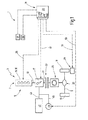
図1には、詳細には図示されていない車両3の装置1の第1実施例の原理回路図が示されている。車両3はドライブトレイン7を備えた駆動装置5を有している。ドライブトレイン7は軸9に取り付けられた車輪11及び13の駆動に使用される。
【0017】
駆動装置5は、ここでは燃焼エンジン16から構成されている内燃機関15と電気機械17とを有している。図示されていないが、電気機械17の回転子は燃焼エンジン16のクランクシャフト19にも、例えば摩擦クラッチであるクラッチ23の入力部21にも回転固定の形で結合されている。例えば電気的又は機械的に操作可能なクラッチ23は、第1の切替位置において、燃焼エンジン16のクランクシャフト19と電気機械17の回転子とを回転させることができ、しかも、これによって車輪11及び13にトルク(駆動トルク又は制動トルク)がかからないように回転させることができる。
【0018】
クラッチ23の代わりにトルクコンバータを使用してもよい。
【0019】
ドライブトレイン7はさらに、例えばマニュアル又はオートマティックトランスミッションであるトランスミッション25と、ディファレンシャル27とを備えている。クラッチ23、トランスミッション25及びディファレンシャル27は、本発明による方法の実行に不可欠ではないオプショナルな装置であることに留意されたい。
【0020】
クラッチ23が閉じているときには、燃焼エンジン16も電気機械17も自らの回転子、クラッチ23、トランスミッション25及びディファレンシャル27を介して車輪11,13とトルク伝達可能な形で結合されており、車輪11及び12に駆動トルク又は制動トルクを伝達することが可能である。駆動装置5のこの実施形態では、燃焼エンジン16と電気機械17は有利にはつねに一緒に使用され、車両3の加速又は減速を行う。例えば、燃焼エンジン16が故障したり、又は(ハイブリッド)車両3を電気エネルギーだけで駆動しなければならない場合には、電気機械17のみを用いて所定のトルクを車輪11,13に供給することも難なく可能である。もちろん、車輪11,13にトルクを供給するために燃焼エンジン16だけを使用し、その一方で、電気機械17は非活動状態にすることも可能である。
【0021】
車両3はさらに車輪11,13を制動するためのブレーキ29を有している。ブレーキ29は図1に示されているように車両3の1つの車輪にのみ割当ててもよいし、又は複数の車輪に割当ててもよい。この種のブレーキ29の構造及び機能は既知であり、ここではその詳細には立ち入らない。
【0022】
装置1は、少なくとも1つの電子制御装置33を備えた制御ユニット31を有しており、燃焼エンジン16のトルクは、破線で表示された制御矢印35によって示されているように、電子制御装置33によって制御可能である。燃焼エンジン16のトルクを変化させることにより、車両3の速度を変化させることができる。電子制御装置33は、車両3の現在/瞬時速度を検知する手段37と、車両3の目標速度を設定する手段39とを有している。これらの手段37,39はそれ自体は公知なので、詳細には説明しない。
【0023】
制御ユニット31は、ただ1つの電子制御装置33の代わりに、相互にデータ接続された複数の制御装置を有していてもよい。
【0024】
電気機械17は車両走行時に発電機として及び電動機として選択的に使用可能である。発電機モードにおいては、電気機械17は車両3の減速(制動)のためのトルクを供給し、電動機モードにおいては、車両3の加速(駆動)のためのトルクを供給する。電気機械17はさらに公知の操作手段を有しており、所望のトルクはこの操作手段を介して設定することができる。これは有利には電子制御装置33を介して行われる。これは破線で表示された制御矢印41によって示されている。
【0025】
電気機械17は、電気ケーブル43及び45を介して、例えばバッテリである蓄電池47及び例えばヒータ又はエアコンである少なくとも1つの負荷49に接続されている。電気機械17の電動機モードにおいては、蓄電池47は車両3の駆動のために電流を供給し、電気機械17の発電機モードにおいては、蓄電池47と負荷49は発生した電流を受け取る。
【0026】
装置1の機能のために:電子制御装置33は、手段39を介して設定された速度を調整するために燃焼エンジン16及び/又は電気機械17にトルクを要求する。このために、電子制御装置33には、有利には、トルクを2つのエンジン16、17に最適に分担させるためのストラテジーが格納されている。燃焼エンジン16と電気機械17とにより車輪11,13に供給されるトルクの合計が車両3に作用する走行抵抗よりも大きければ、車両3の加速がもたらされる。別のケースでは、つまり、燃焼エンジン16と電気機械17とにより車輪11,13に供給されるトルクの合計が走行抵抗よりも小さい場合には、車両3の減速がもたらされる。手段37を介して検知された車両3の現在速度が手段39を介して設定された目標速度よりも高いため、電子制御装置33が車両3の速度を低下させようとする場合には、破線で表示された制御矢印51によって示されているように、ブレーキ29も電子制御装置33によって操作されるようにし、燃焼エンジン16と電気機械17のみによって可能となるよりもさらに強く速度を低下させることができる。
【0027】
車両3を減速すべきケースにおいて、蓄電池47が電気機械により発生された電流のすべてを受け入れることができず、電気機械17の制動トルクによる車両3の減速では十分でない場合、電子制御装置33は少なくとも1つの電気負荷49において電気入力を増大させる。電子制御装置33による電気負荷の制御は、破線で表示された制御矢印53によって示されている。
【0028】
以下では、車速調整の特に有利な実施形態を説明する。この実施形態は、少なくとも1つの電気機械と少なくとも1つの内燃機関とを有する駆動装置、すなわち、例えば図1に基づいて説明されたような駆動装置を備えた車両において使用可能である。
【0029】
上記車速調整器は、活動化されると、車両の速度を一定に又は実質的に一定に保とうとする。これは、起伏のある地形での走行時には所要駆動トルクの著しい変化をもたらす。したがって、本発明によれば、駆動トルクの調整は、電気機械によって、また、内燃機関をできるだけ恒常的に使用することによって十分に実施される。この場合、内燃機関は走行力学方程式から得られる基本駆動トルクを供給する。この基本駆動トルクは、燃料消費及び/又は排ガス放出ができるだけ少ない内燃機関の作動点において設定される。所要全駆動トルクの短期間の変動は専ら電気機械により補正される。CVTもしくはオートマティックトランスミッション及びドライブトレイン協調制御との連携は、さらなる最適化の可能性を提供する。これにより、内燃機関はできるだけ低い回転数で動作することができ、ガソリンエンジンの場合であれば、できるだけスロットルを閉めない状態で動作することができる。このことの利点は、内燃機関(燃焼エンジン)がたいてい低燃費で且つ排ガスの放出も少なく動作することができ、電動機のトルクはたいてい回転数が低いときに最大となり、したがってまた達成すべき効率も最大となることにある。
【0030】
以下では、上記方法を図4に基づいてより詳細に説明する。グラフIは、電気機械により供給されるトルクME、内燃機関により供給されるトルクMB及び個々のトルクから構成された所望/所要の全駆動トルクを、グラフIIに示されている走行距離数曲線に関連させて示している。車速を一定に保つために、過度に高い速度は回生ブレーキ(蓄電池(バッテリ)の充電)により補正され、その一方で、過度に低い車速は電気機械による正のトルクの出力により補正される。蓄電池の比較的長い充電又は放電期間(t>Tmax)のときにはじめて、内燃機関のトルクは積分器を介して増減調整され、全駆動トルクにおける電気機械の成分が相応してゼロの方向に戻される。つまり、t0からt6までの時間、内燃機関のトルクは一定であり、時点t6以降になってようやく上昇し始める。というのも、この時点において、バッテリの放電期間がTmaxよりも長くなり、電気機械のトルクがゼロに向かって戻されるからである。電気機械の補助トルクが、車両のターゲット速度(目標速度)を維持するのに十分でない場合には、内燃機関のトルクか又は変速比が適応調整される。
【0031】
図4からは、車速調整器が活動化状態にあるときには、車両を所望の速度に一定に保つために、全トルクが電気機械と内燃機関との間で整合的に分担されることが直ちに明らかである。平坦な走行区間及び勾配が一定の走行区間では、所望の速度の調整は高い精度で且つ車速調整器をあまり動作させずに達成される。全トルクの分担と、内燃機関の作動点をできるだけ広い範囲で変化させないようにすることによってはじめて、一定速度での長い走行区間においても燃費を低く抑えることができる。
【0032】
図2には、装置1の第2実施例の原理回路図が示されている。同じ部分には同じ参照記号が付されているので、その限りにおいて、図1の説明が参照される。したがって、以下では、相違点についてより詳細に説明する。
【0033】
車両3は駆動装置5’を有している。駆動装置5’は第1及び第2のドライブトレイン7及び7’を有しており、このうちドライブトレイン7は軸9(前車軸又は後車軸)の車輪11,13に割当てられており、他方のドライブトレイン7’は第2の軸9’(後車軸又は前車軸)の車輪11’に割当てられている。第1のドライブトレイン7は燃焼エンジン16、クラッチ23、トランスミッション25及びディファレンシャル27を有しており、車輪11,13の駆動に使用される。第2のドライブトレイン7’は、車両3に駆動トルク又は制動トルクを供給するため、駆動部21を介して車両3の他方の軸9’の車輪11’に回転固定の形で結合された電気機械17を有している。
【0034】
図2では、別の変形実施形態において、電気機械17がディファレンシャル27’を用いて軸9’においてさらに少なくとも1つの別の車輪13’を駆動することができることが、破線により示されている。第2のドライブトレイン7’の図示されていない第3の変形実施形態においては、少なくとも2つの電気機械が設けられており、それぞれ車輪11’、13’のうちの1つとトルク伝達可能な形で結合されている。同じく図示されていない第4の変形実施形態では、軸9に割当てられたドライブトレイン7は、図1に基づいて説明したドライブトレイン7と同一の構成を有しており、その一方で、軸9’又は車輪11’にのみ割当てられた少なくとも1つの別のドライブトレイン7’は、上で説明したように形成されている。
【0035】
図2に基づいて説明した実施例の車速調整方法は、実質的に図1に基づいて説明した方法と一致している。つまり、電子制御装置33は、電気機械17及び燃焼エンジン16とは互いに独立して、車両3の実際速度と目標速度とに依存するトルクを要求することができる。したがって、第2の軸9’の車輪11’又は車輪11’及び13’ならびに第1の軸9の車輪11及び13に、それぞれ異なるトルク又は異なる大きさのトルクを供給することは難なく可能である。このことは特定の走行状況においては有利でありうる。
【0036】
図2による実施例は、とりわけ、燃焼エンジン16と電気機械17とが互いに独立して制御可能であり、各々にとっての他方の軸又は1つの車軸につき少なくとも1つの車輪が、各々にとっての他方の車輪とは独立して駆動可能である点で、図1に基づいて説明した実施例とは異なっている。図2に示されている駆動装置は全輪駆動が可能であることに留意されたい。
【0037】
図3には、装置1の第3の実施例の原理回路図が示されている。図1及び2において既に説明した部分には同じ参照記号が付されている。したがって、図1及び2の説明が参照される。車両はドライブトレイン7をただ1つだけ備えた駆動装置5’’を有している。このドライブトレイン7は少なくとも1つの電気機械を有しているが、内燃機関は有していない。つまり、これは純粋な電気自動車である。電気機械17はここでは直接、駆動部分21とディファレンシャル27とを介して軸9の両方の車輪11,13に回転固定の形で結合されている。択一的に、ディファレンシャルを使用せず、電気機械17だけを車輪11,13の一方にのみ直接結合してもよい。別の変形実施形態では、各々車両の1つの車輪を駆動する複数の電気機械が設けられている。この場合、これらの車輪は異なる軸上にあってもよい。
【0038】
図3に示されている実施例では、ドライブトレイン7内に、クラッチ23もトランスミッション25も設けられていない。しかしながら、これらの装置をドライブトレイン7内に設けることは難なく可能である。
【0039】
図3に示されている駆動装置5’’では、蓄電池47としての少なくとも1つのバッテリの代わりに、少なくとも1つの燃料電池、有利には複数の燃料電池を電流源として設けてもよい。
【0040】
図3に示されている実施例により実現可能な車両3の車速調整方法は、図1及び2に基づいて説明した方法と類似している。つまり、電子制御装置33は、手段37を介して検知された車両3の現在の車速が手段39により設定された目標速度よりも低いことを確認すると、車両3の加速をもたらす正のトルクを電気機械17に要求する。電子制御装置33が実際速度と目標速度との比較により車両3の減速を要求すると、データ接続35を介して負のトルクが電気機械17に要求される。この実施例においても、電気機械17の負のトルクだけでは十分でない場合には、制御装置33が少なくとも1つの車輪11に対するブレーキ29も操作して、車両3をより強く減速するようにすると有利である。最後に、この実施例においても、蓄電池47が電気機械の発電機モードにおいて発生したすべての電流を受け入れることができず、電気機械17による制動トルクが十分でない場合には、電子制御装置33が少なくとも1つの電気負荷49において電流の受け入れを増大させることが可能である。
【図面の簡単な説明】
【図1】
車両のドライブトレインの原理回路図を示す。
【図2】
車両のドライブトレインの原理回路図を示す。
【図3】
車両のドライブトレインの原理回路図を示す。
【図4】
車速が一定の場合の駆動トルクの要求総量(グラフI)を走行距離数の曲線(グラフII)に関連させて表示する2つのグラフを示す。[0001]
The invention relates to a device for adjusting the running speed of a vehicle according to the superordinate concept of claim 1 and to a method for adjusting the running speed of a vehicle according to the superordinate concept of claim 10.
[0002]
State of the Art Apparatus and methods as described above are well known. They ACC system (A daptive C ruise C ontrol) , also known as a vehicle speed regulator or cruise control, it is used to speed adjustment of the motor vehicle.
[0003]
An automobile having an electric machine in addition to an internal combustion engine in a drive train is known. This type of electric machine in a car drive train is also called a starter dynamo, crankshaft starter dynamo or built-in starter dynamo.
[0004]
A device as described above is known from DE 199 14 428 C1. In this apparatus, the braking torque of the electric machine in the drive train is set in cooperation with the automatic speed / distance adjustment system. In this regard, the electric machine coupled to the combustion engine always generates electricity as an alternator when the vehicle is running in order to brake the combustion engine and thus also to supply load torque to the drive train.
[0005]
Advantages of the invention On the other hand, the device according to the invention with the features described in claim 1 is a device for adjusting at least one electric machine provided in the vehicle for adjusting the running speed of the vehicle. It provides the advantage that it can be used in various ways in conjunction with a vehicle speed regulator, that is, it can be used not only for braking but also for acceleration of the vehicle. To this end, in the present invention, the electric machine is selectively operated in the generator mode and the motor mode. However, each operating mode is used by the vehicle speed regulator depending on at least one instantaneous (actual) speed and a pre-set target speed and possibly also depending on at least one other parameter. The
[0006]
This device can be used for vehicles equipped with an internal combustion engine and an electric machine as well as for vehicles driven exclusively using at least one electric motor.
[0007]
This device has a control unit for controlling the torque of the electric machine and means for operating the electric machine, and a desired torque (drive torque or braking torque) can be set via these. it can. Furthermore, means for detecting the actual speed of the vehicle and means for setting the target speed of the vehicle are also provided. The actual speed can be detected in various ways. For example, the actual speed can be detected using a sensor that detects the rotational speed of the wheel. Similarly, a plurality of methods can be considered for setting the target speed. For example, a passenger, in particular a driver, can set a desired speed via the operating element. The means for setting the target speed may further comprise means for adjusting the distance from the vehicle to the object, in particular the distance to the vehicle traveling ahead (speed and distance adjustment system, for example an ACC system). In a third variant embodiment, the target speed is given in advance to the control unit via a data connection, for example a satellite connection.
[0008]
Advantageous embodiments of the device are obtained by a combination of features that emerge from the dependent claims.
[0009]
The invention also relates to a drive device for a vehicle comprising at least one electric machine and possibly also an internal combustion engine, with the features as claimed in claim 9.
[0010]
The invention further relates to a method with the features as claimed in claim 10. This method requires that the vehicle be decelerated if the actual speed is higher than the target speed, so that the electric machine is operated as a generator, and if the actual speed is lower than the target speed, the electric machine is It is excellent in that it operates as an electric motor. When the vehicle has an internal combustion engine in addition to the electric machine, the torque required depending on the actual speed and the target speed of the vehicle by the vehicle speed regulator is selectively selected according to the structure of the drive device. Obtained from an electric machine or an internal combustion engine or from an electric machine and an internal combustion engine and transmitted to at least one wheel of the vehicle. For this reason, a strategy for optimally sharing the requested torque between the electric machine and the internal combustion engine can be stored in the control unit of the vehicle speed regulator. If the total torque transmitted to the at least one wheel is greater than the running resistance acting on the vehicle, the vehicle is accelerated, while if the total torque is less than the running resistance, the vehicle is decelerated (braking) ) Is brought about.
[0011]
Alternatively or additionally, a braking device assigned to at least one wheel of the vehicle may be activated in order to reduce the vehicle speed. Thereby, the vehicle speed can be reduced more strongly than is possible only by the internal combustion engine and the electric machine.
[0012]
Advantageous embodiments of the method result from the combination of features that emerge from the dependent claims.
[0013]
Hereinafter, the present invention will be described in more detail with reference to the accompanying drawings.
[0014]
1-3 show the principle circuit diagram of the vehicle drive train,
FIG. 4 shows two graphs that display the required total amount of drive torque (graph I) when the vehicle speed is constant in relation to the travel distance curve (graph II).
[0015]
Description of Embodiments In the following, a plurality of embodiments of the apparatus 1 for automatically adjusting the traveling speed of a vehicle such as a passenger car (Pkw), a truck (Lkw), a bus, etc. will be described based on the drawings.
[0016]
FIG. 1 shows a principle circuit diagram of a first embodiment of a device 1 of a vehicle 3 not shown in detail. The vehicle 3 has a drive device 5 having a drive train 7. The drive train 7 is used to drive
[0017]
The drive device 5 has an internal combustion engine 15 and an
[0018]
A torque converter may be used instead of the
[0019]
The drive train 7 further includes a
[0020]
When the clutch 23 is closed, both the combustion engine 16 and the
[0021]
The vehicle 3 further has a
[0022]
The device 1 has a control unit 31 with at least one
[0023]
The control unit 31 may include a plurality of control devices connected to each other in place of the single
[0024]
The
[0025]
The
[0026]
For the function of the device 1: the
[0027]
In the case where the vehicle 3 is to be decelerated, if the
[0028]
In the following, a particularly advantageous embodiment of the vehicle speed adjustment will be described. This embodiment can be used in a drive device having at least one electric machine and at least one internal combustion engine, i.e. a drive device as described, for example, with reference to FIG.
[0029]
When activated, the vehicle speed regulator attempts to keep the vehicle speed constant or substantially constant. This results in a significant change in the required drive torque when traveling on rough terrain. Therefore, according to the invention, the adjustment of the drive torque is sufficiently performed by the electric machine and by using the internal combustion engine as constantly as possible. In this case, the internal combustion engine supplies a basic driving torque obtained from the running dynamic equation. This basic drive torque is set at the operating point of the internal combustion engine where fuel consumption and / or exhaust gas emissions are as low as possible. Short-term fluctuations in the total required drive torque are compensated exclusively by the electric machine. Coordination with CVT or automatic transmission and drivetrain coordinated control offers further optimization possibilities. As a result, the internal combustion engine can operate at the lowest possible rotational speed, and in the case of a gasoline engine, it can operate with the throttle closed as little as possible. The advantage of this is that the internal combustion engine (combustion engine) can usually be operated with low fuel consumption and low emissions, and the torque of the motor is usually maximized at low speeds and therefore also the efficiency to be achieved. It is to become the maximum.
[0030]
Below, the said method is demonstrated in detail based on FIG. Graph I, the torque M E supplied by the electric machine, the desired / required total drive torque which is composed of a torque M B and individual torque supplied by the internal combustion engine, mileage number shown in the graph II Shown in relation to the curve. In order to keep the vehicle speed constant, an excessively high speed is corrected by a regenerative brake (charging of a storage battery (battery)), while an excessively low vehicle speed is corrected by a positive torque output by an electric machine. Only during a relatively long charging or discharging period (t> T max ) of the storage battery, the torque of the internal combustion engine is adjusted up or down via an integrator, so that the components of the electric machine in the total driving torque are correspondingly zero. Returned. That is, the torque of the internal combustion engine is constant during the period from t 0 to t 6 , and finally begins to increase after time t 6 . This is because at this point, the battery discharge period is longer than T max and the torque of the electric machine is returned to zero. If the auxiliary torque of the electric machine is not sufficient to maintain the target speed (target speed) of the vehicle, the torque of the internal combustion engine or the gear ratio is adaptively adjusted.
[0031]
From FIG. 4 it is readily apparent that when the vehicle speed regulator is in the activated state, all torque is shared consistently between the electric machine and the internal combustion engine to keep the vehicle constant at the desired speed. It is. In a flat travel section and a travel section with a constant slope, the desired speed adjustment is achieved with high accuracy and with little operation of the vehicle speed regulator. The fuel consumption can be kept low even in a long traveling section at a constant speed only by sharing the total torque and preventing the operating point of the internal combustion engine from changing in the widest possible range.
[0032]
FIG. 2 shows a principle circuit diagram of a second embodiment of the device 1. The same parts are denoted by the same reference symbols, and as such, the description of FIG. 1 is referred to. Accordingly, the difference will be described in more detail below.
[0033]
The vehicle 3 has a drive device 5 ′. The drive device 5 'has first and second drive trains 7 and 7', of which the drive train 7 is assigned to the
[0034]
In FIG. 2, in another variant embodiment, the dashed line indicates that the
[0035]
The vehicle speed adjustment method of the embodiment described based on FIG. 2 substantially matches the method described based on FIG. That is, the
[0036]
The embodiment according to FIG. 2, inter alia, allows the combustion engine 16 and the
[0037]
FIG. 3 shows a principle circuit diagram of a third embodiment of the device 1. Parts already described in FIGS. 1 and 2 bear the same reference symbols. Therefore, reference is made to the description of FIGS. The vehicle has a drive unit 5 ″ with only one drive train 7. The drive train 7 has at least one electric machine, but does not have an internal combustion engine. In short, this is a pure electric car. Here, the
[0038]
In the embodiment shown in FIG. 3, neither the clutch 23 nor the
[0039]
In the drive device 5 ″ shown in FIG. 3, instead of at least one battery as the
[0040]
The vehicle speed adjustment method of the vehicle 3 that can be realized by the embodiment shown in FIG. 3 is similar to the method described with reference to FIGS. That is, when the
[Brief description of the drawings]
[Figure 1]
The principle circuit diagram of the drive train of a vehicle is shown.
[Figure 2]
The principle circuit diagram of the drive train of a vehicle is shown.
[Fig. 3]
The principle circuit diagram of the drive train of a vehicle is shown.
[Fig. 4]
2 shows two graphs that display the required total amount of driving torque (graph I) when the vehicle speed is constant in relation to the curve of the number of mileage (graph II).
Claims (18)
前記電気機械(17)は制動トルクを発生させる発電機モード中も駆動トルクを発生させる電動機モード中も使用可能であることを特徴とする、走行速度を調整するための装置。At least one vehicle speed having an electric machine (17) coupled to or connectable to a drive train (7, 7 ') for at least one wheel (11, 13; 11', 13 ') A device for adjusting depending on the speed and the target speed, a control unit (31) for controlling the torque of the electric machine (17), means for operating the electric machine (17), In an apparatus of the type having means (37) for detecting the actual speed of the vehicle (3) and means (39) for setting a target speed of the vehicle (3),
The device for adjusting the running speed, characterized in that the electric machine (17) can be used both in the generator mode for generating braking torque and in the motor mode for generating driving torque.
少なくとも1つの電気機械(17)と、場合よっては内燃機関と、前記車両(3)の走行速度を制御するための請求項1から8のいずれか1項記載の装置とを有し、
前記少なくとも1つの電気機械(17)及び前記内燃機関が、それぞれ少なくとも1つの車輪に対するドライブトレイン(7,7’)に結合されている又は結合可能である、ことを特徴とする駆動装置。In the drive device (5; 5 ′, 5 ″) of the vehicle (3),
At least one electric machine (17), possibly an internal combustion engine, and a device according to any one of the preceding claims for controlling the traveling speed of the vehicle (3),
Drive device, characterized in that the at least one electric machine (17) and the internal combustion engine are each coupled to or connectable to a drive train (7, 7 ') for at least one wheel.
実際速度が目標速度よりも高い場合には、前記車両(3)の減速を要求し、このために前記電気機械(17)を発電機として作動させ、
実際速度が目標速度よりも低い場合には、前記電気機械(17)を電動機として使用することを特徴とする走行速度を調整するための方法。A method for adjusting the travel speed of a vehicle (3) having at least one electric machine (17) depending on at least the actual speed of the travel speed and a requested target speed, said actual speed being detected The target speed can be set, and the actual speed and the target speed are compared.
If the actual speed is higher than the target speed, the vehicle (3) is requested to decelerate, for this purpose the electric machine (17) is operated as a generator,
A method for adjusting the running speed, characterized in that when the actual speed is lower than the target speed, the electric machine (17) is used as an electric motor.
前記電気機械(17)の発電機モードにおいては、発生した電流を前記少なくとも1つの蓄電池(47)及び/又は少なくとも1つの電気負荷(49)に受け入れる、請求項1から12のいずれか1項記載の方法。In the electric motor mode of the electric machine (17), in order to drive the vehicle (3), current is supplied from the at least one storage battery (47) to the electric machine,
13. The generator according to claim 1, wherein in the generator mode of the electric machine (17), the generated current is received by the at least one storage battery (47) and / or at least one electric load (49). the method of.
Applications Claiming Priority (2)
| Application Number | Priority Date | Filing Date | Title |
|---|---|---|---|
| DE10162017A DE10162017A1 (en) | 2001-12-18 | 2001-12-18 | Device and method for regulating the speed of a vehicle |
| PCT/DE2002/004516 WO2003051663A1 (en) | 2001-12-18 | 2002-12-10 | Device and method for adjusting the speed of a vehicle |
Publications (2)
| Publication Number | Publication Date |
|---|---|
| JP2005512498A true JP2005512498A (en) | 2005-04-28 |
| JP2005512498A5 JP2005512498A5 (en) | 2007-02-22 |
Family
ID=7709568
Family Applications (1)
| Application Number | Title | Priority Date | Filing Date |
|---|---|---|---|
| JP2003552565A Pending JP2005512498A (en) | 2001-12-18 | 2002-12-10 | Apparatus and method for adjusting the running speed of a vehicle |
Country Status (5)
| Country | Link |
|---|---|
| US (2) | US20040129470A1 (en) |
| EP (1) | EP1458586B1 (en) |
| JP (1) | JP2005512498A (en) |
| DE (2) | DE10162017A1 (en) |
| WO (1) | WO2003051663A1 (en) |
Cited By (3)
| Publication number | Priority date | Publication date | Assignee | Title |
|---|---|---|---|---|
| KR101305779B1 (en) * | 2011-07-21 | 2013-09-17 | 현대자동차주식회사 | Vehicle travel torque control system and control method thereof |
| JPWO2013065168A1 (en) * | 2011-11-04 | 2015-04-02 | トヨタ自動車株式会社 | Vehicle and vehicle control method |
| KR101511678B1 (en) | 2012-09-17 | 2015-04-17 | 한국에너지기술연구원 | Method for managing fuel cell vehicle system |
Families Citing this family (32)
| Publication number | Priority date | Publication date | Assignee | Title |
|---|---|---|---|---|
| DE10352799A1 (en) | 2003-11-12 | 2005-06-23 | Robert Bosch Gmbh | Cruise control for motor vehicles |
| US7894971B2 (en) | 2005-12-28 | 2011-02-22 | Toyota Jidosha Kabushiki Kaisha | Vehicle control apparatus |
| DE102006017176A1 (en) * | 2006-04-12 | 2007-10-18 | Robert Bosch Gmbh | Speed control device and motor vehicle with such a speed control device |
| JP4554551B2 (en) | 2006-04-28 | 2010-09-29 | 本田技研工業株式会社 | Vehicle travel control device |
| JP4314250B2 (en) * | 2006-05-23 | 2009-08-12 | トヨタ自動車株式会社 | Road surface determination device for vehicles |
| JP4713408B2 (en) * | 2006-06-07 | 2011-06-29 | トヨタ自動車株式会社 | Vehicle control device |
| US7867122B2 (en) * | 2006-09-26 | 2011-01-11 | Epi-Energy Ltd. | Power transmission system with continuously variable speed control |
| US8430792B2 (en) * | 2006-11-08 | 2013-04-30 | GM Global Technology Operations LLC | Downhill vehicle speed control algorithm for electric driven vehicles |
| US7828693B2 (en) * | 2007-06-20 | 2010-11-09 | Ford Global Technologies, Llc | Negative driveline torque control incorporating transmission state selection for a hybrid vehicle |
| US7841433B2 (en) * | 2007-06-20 | 2010-11-30 | Ford Global Technologies, Llc | Negative driveline torque control incorporating transmission state selection for a hybrid vehicle |
| DE102007029809A1 (en) | 2007-06-27 | 2009-01-08 | Dr. Ing. H.C. F. Porsche Aktiengesellschaft | Method for controlling a drive train for a hybrid vehicle |
| US7703563B2 (en) | 2007-07-02 | 2010-04-27 | Gm Global Technology Operations, Inc. | Control of hybrid power regeneration during cruise control |
| JP4854609B2 (en) * | 2007-07-04 | 2012-01-18 | トヨタ自動車株式会社 | Vehicle control device |
| DE102007035722A1 (en) | 2007-07-30 | 2009-02-05 | Robert Bosch Gmbh | Method and device for specifying an output variable of a drive unit |
| US7908067B2 (en) | 2007-12-05 | 2011-03-15 | Ford Global Technologies, Llc | Hybrid electric vehicle braking downshift control |
| US8596390B2 (en) * | 2007-12-05 | 2013-12-03 | Ford Global Technologies, Llc | Torque control for hybrid electric vehicle speed control operation |
| US8334679B2 (en) * | 2008-01-22 | 2012-12-18 | Honda Motor Co., Ltd. | ACG output voltage control |
| US8217631B2 (en) | 2008-01-22 | 2012-07-10 | Honda Motor Co., Ltd. | ACG output voltage control |
| DE102008051001A1 (en) * | 2008-10-13 | 2010-04-15 | Volkswagen Ag | Distance controlling device for hybrid vehicle, has hydraulic brake assembly controlled by vehicle speed controlling device such that brake torque is applied exclusively by hydraulic brake assembly during stopping of motor vehicle |
| JP5491721B2 (en) * | 2008-11-12 | 2014-05-14 | 本田技研工業株式会社 | Control device for electric power steering device |
| JP2011110943A (en) * | 2009-11-24 | 2011-06-09 | Denso Corp | Controller for vehicle drive system |
| EP2460704B1 (en) * | 2010-12-06 | 2019-01-23 | Iveco S.p.A. | Method for actuating the cruise control function in a vehicle equipped with hybrid driving, especially an industrial or commercial vehicle |
| US9937918B2 (en) * | 2011-04-20 | 2018-04-10 | Nilfisk A/S | Hybrid sweeper-scrubber control method and system |
| WO2013027288A1 (en) * | 2011-08-24 | 2013-02-28 | トヨタ自動車株式会社 | Vehicle travel control apparatus |
| DE102011084929A1 (en) * | 2011-10-21 | 2013-04-25 | Zf Friedrichshafen Ag | Method for operating a drive train of a hybrid vehicle |
| US9096211B2 (en) | 2012-03-14 | 2015-08-04 | Caterpillar Inc. | Control system having powertrain lock |
| FR2994546B1 (en) * | 2012-08-16 | 2015-09-04 | Peugeot Citroen Automobiles Sa | TORQUE LIMITING METHOD OF A HYBRID VEHICLE ELECTRIC MACHINE COMPRISING A SPEED CONTROL SYSTEM |
| GB2508668A (en) * | 2012-12-10 | 2014-06-11 | Jaguar Land Rover Ltd | Adaptive cruise control (ACC) means for a host vehicle having regenerative and non-regenerative braking means |
| GB2508670A (en) | 2012-12-10 | 2014-06-11 | Jaguar Land Rover Ltd | Hybrid vehicle and boost control for gradients |
| DE102014209395A1 (en) * | 2014-05-19 | 2015-11-19 | Robert Bosch Gmbh | Method for reducing drag torque fluctuations during electrical starting |
| FR3088880A1 (en) * | 2018-11-28 | 2020-05-29 | Psa Automobiles Sa | METHOD AND DEVICE FOR CONTROLLING MIXED-PHASE DECELERATION, FOR A VEHICLE WITH AUTOMATED DRIVING AND NON-THERMAL DRIVE MACHINE |
| CN112297875B (en) * | 2020-10-27 | 2022-04-15 | 中车青岛四方机车车辆股份有限公司 | Control method and control system for constant-speed running of rail transit vehicle and vehicle |
Family Cites Families (34)
| Publication number | Priority date | Publication date | Assignee | Title |
|---|---|---|---|---|
| US4093900A (en) * | 1976-08-11 | 1978-06-06 | General Electric Company | Dynamic brake blending for an inverter propulsion system |
| US5081365A (en) * | 1990-06-06 | 1992-01-14 | Field Bruce F | Electric hybrid vehicle and method of controlling it |
| JPH06255389A (en) * | 1991-02-26 | 1994-09-13 | Mitsubishi Electric Corp | Traveling controller for vehicle |
| JPH0549106A (en) | 1991-08-09 | 1993-02-26 | Nissan Motor Co Ltd | Motor controller |
| JPH05111109A (en) * | 1991-10-08 | 1993-04-30 | Mitsubishi Heavy Ind Ltd | Control method for electric vehicle driven through internal-combustion engine |
| US5301764A (en) * | 1992-04-13 | 1994-04-12 | Gardner Conrad O | Hybrid motor vehicle having an electric motor and utilizing an internal combustion engine for fast charge during cruise mode off condition |
| JPH06319205A (en) | 1993-04-30 | 1994-11-15 | Aqueous Res:Kk | Hybrid vehicle |
| US5823280A (en) * | 1995-01-12 | 1998-10-20 | Nevcor, Inc. | Hybrid parallel electric vehicle |
| US5544056A (en) * | 1995-01-23 | 1996-08-06 | Seireg; Ali A. | Computerized control of automobile speed |
| JP3011045B2 (en) | 1995-03-15 | 2000-02-21 | トヨタ自動車株式会社 | Electric car |
| JP3534271B2 (en) * | 1995-04-20 | 2004-06-07 | 株式会社エクォス・リサーチ | Hybrid vehicle |
| JP3612828B2 (en) | 1995-11-30 | 2005-01-19 | 株式会社エクォス・リサーチ | Hybrid vehicle |
| FR2742100B1 (en) * | 1995-12-08 | 1998-01-09 | Renault | HYBRID MOTOR VEHICLE |
| JP3255012B2 (en) * | 1996-05-02 | 2002-02-12 | トヨタ自動車株式会社 | Hybrid car |
| DE19618865C2 (en) | 1996-05-10 | 2002-08-08 | Zf Sachs Ag | Drive arrangement for a hybrid vehicle |
| US5710699A (en) * | 1996-05-28 | 1998-01-20 | General Electric Company | Power electronic interface circuits for batteries and ultracapacitors in electric vehicles and battery storage systems |
| JPH1023603A (en) | 1996-07-05 | 1998-01-23 | Toyota Motor Corp | Controller for hybrid vehicle |
| JP3447937B2 (en) * | 1997-11-18 | 2003-09-16 | 本田技研工業株式会社 | Hybrid vehicle |
| GB9818960D0 (en) * | 1998-09-02 | 1998-10-21 | Rover Group | A vehicle |
| US6209672B1 (en) * | 1998-09-14 | 2001-04-03 | Paice Corporation | Hybrid vehicle |
| JP3893778B2 (en) * | 1998-11-09 | 2007-03-14 | トヨタ自動車株式会社 | Lock-up clutch control device |
| JP3546735B2 (en) * | 1999-01-18 | 2004-07-28 | 日産自動車株式会社 | Engine start control device |
| CN100349763C (en) * | 1999-02-08 | 2007-11-21 | 丰田自动车株式会社 | Vehicle braked by motor torque and method of controlling the vehicle |
| DE19914428C1 (en) * | 1999-03-30 | 2000-11-30 | Mannesmann Sachs Ag | Automobile propulsion drive has loading of i.c. engine by combined generator/starter motor electrical machine increased via electronic control for selective braking of automobile |
| AU760387B2 (en) * | 1999-08-05 | 2003-05-15 | Honda Giken Kogyo Kabushiki Kaisha | Control device of hybrid vehicle |
| DE19937381A1 (en) * | 1999-08-07 | 2001-03-22 | Daimler Chrysler Ag | Motor vehicle with hybrid drive has event detector generating signals identifying external event; control signal affecting engine and/or motor can be generated depending on event signal |
| US6122588A (en) * | 1999-10-19 | 2000-09-19 | Ford Global Technologies, Inc. | Vehicle speed control with continuously variable braking torque |
| DE19955313C2 (en) | 1999-11-17 | 2003-12-18 | Jungheinrich Ag | Drive system for industrial trucks |
| JP3563314B2 (en) | 1999-11-25 | 2004-09-08 | 本田技研工業株式会社 | Auto cruise control system for hybrid vehicles |
| JP3991538B2 (en) | 1999-12-02 | 2007-10-17 | トヨタ自動車株式会社 | Vehicle control device |
| JP4240713B2 (en) | 2000-01-07 | 2009-03-18 | トヨタ自動車株式会社 | Vehicle control device |
| US6484833B1 (en) * | 2000-03-17 | 2002-11-26 | General Motors Corporation | Apparatus and method for maintaining state of charge in vehicle operations |
| US6278916B1 (en) * | 2000-05-09 | 2001-08-21 | Ford Global Technologies, Inc. | Torque control strategy for management of creep and grade hold torque in a wheeled vehicle whose powertrain includes a rotary electric machine |
| JP3454226B2 (en) * | 2000-05-11 | 2003-10-06 | トヨタ自動車株式会社 | Control device for hybrid vehicle |
-
2001
- 2001-12-18 DE DE10162017A patent/DE10162017A1/en not_active Ceased
-
2002
- 2002-12-10 JP JP2003552565A patent/JP2005512498A/en active Pending
- 2002-12-10 DE DE50207340T patent/DE50207340D1/en not_active Expired - Lifetime
- 2002-12-10 WO PCT/DE2002/004516 patent/WO2003051663A1/en active IP Right Grant
- 2002-12-10 EP EP02794983A patent/EP1458586B1/en not_active Expired - Lifetime
- 2002-12-10 US US10/468,540 patent/US20040129470A1/en not_active Abandoned
-
2007
- 2007-01-16 US US11/654,062 patent/US7416037B2/en not_active Expired - Lifetime
Cited By (4)
| Publication number | Priority date | Publication date | Assignee | Title |
|---|---|---|---|---|
| KR101305779B1 (en) * | 2011-07-21 | 2013-09-17 | 현대자동차주식회사 | Vehicle travel torque control system and control method thereof |
| JPWO2013065168A1 (en) * | 2011-11-04 | 2015-04-02 | トヨタ自動車株式会社 | Vehicle and vehicle control method |
| US9114726B2 (en) | 2011-11-04 | 2015-08-25 | Toyota Jidosha Kabushiki Kaisha | Vehicle and method for controlling vehicle |
| KR101511678B1 (en) | 2012-09-17 | 2015-04-17 | 한국에너지기술연구원 | Method for managing fuel cell vehicle system |
Also Published As
| Publication number | Publication date |
|---|---|
| EP1458586A1 (en) | 2004-09-22 |
| DE50207340D1 (en) | 2006-08-03 |
| US20070114084A1 (en) | 2007-05-24 |
| EP1458586B1 (en) | 2006-06-21 |
| WO2003051663A1 (en) | 2003-06-26 |
| US20040129470A1 (en) | 2004-07-08 |
| DE10162017A1 (en) | 2003-07-10 |
| US7416037B2 (en) | 2008-08-26 |
Similar Documents
| Publication | Publication Date | Title |
|---|---|---|
| JP2005512498A (en) | Apparatus and method for adjusting the running speed of a vehicle | |
| US7632212B2 (en) | Hybrid vehicle and control method of the same | |
| US10525968B2 (en) | Method for controlling a drive device of a hybrid vehicle and hybrid vehicle | |
| US6484833B1 (en) | Apparatus and method for maintaining state of charge in vehicle operations | |
| US7721833B2 (en) | Hybrid vehicle, control method of hybrid vehicle, and power output apparatus | |
| JP4453746B2 (en) | POWER OUTPUT DEVICE, ITS CONTROL METHOD, AND VEHICLE | |
| JP3612711B2 (en) | Automobile | |
| JP3947082B2 (en) | Control method of hybrid electric vehicle to obtain maximum fully open acceleration performance | |
| EP1768868B1 (en) | Power output apparatus, motor vehicle equipped with power output apparatus, and control method of power output apparatus | |
| US6691809B2 (en) | Power output apparatus, motor vehicle including power output apparatus and control methods thereof | |
| JP4229105B2 (en) | Hybrid vehicle and control method thereof | |
| US20100250042A1 (en) | Vehicle and method of controlling the vehicle | |
| CN104684784A (en) | Control system for hybrid vehicle | |
| JP4086042B2 (en) | Automobile and control method thereof | |
| EP0822114A2 (en) | Control system for hybrid vehicle | |
| US20170203644A1 (en) | Hybrid Drive System | |
| JP3995097B2 (en) | Method for adjusting the target operating state of a hybrid drive of a vehicle | |
| EP1491378B1 (en) | Control device for hybrid vehicle | |
| JP2005020955A (en) | Charging and discharging control device for energy storage device and car | |
| JP4365354B2 (en) | Power output apparatus, automobile equipped with the same, and control method of power output apparatus | |
| JP2005210841A (en) | Vehicle and method for controlling the same | |
| JP3948099B2 (en) | Power output device and hybrid vehicle | |
| JP4066985B2 (en) | Power output apparatus, automobile equipped with the same, and control method of power output apparatus | |
| JP4031769B2 (en) | Power output device, automobile equipped with the same, and power transmission device | |
| JP2001268807A (en) | Battery charge control device of vehicle |
Legal Events
| Date | Code | Title | Description |
|---|---|---|---|
| A621 | Written request for application examination |
Free format text: JAPANESE INTERMEDIATE CODE: A621 Effective date: 20051209 |
|
| A131 | Notification of reasons for refusal |
Free format text: JAPANESE INTERMEDIATE CODE: A131 Effective date: 20060622 |
|
| A601 | Written request for extension of time |
Free format text: JAPANESE INTERMEDIATE CODE: A601 Effective date: 20060920 |
|
| A602 | Written permission of extension of time |
Free format text: JAPANESE INTERMEDIATE CODE: A602 Effective date: 20060927 |
|
| A521 | Request for written amendment filed |
Free format text: JAPANESE INTERMEDIATE CODE: A523 Effective date: 20061222 |
|
| A524 | Written submission of copy of amendment under article 19 pct |
Free format text: JAPANESE INTERMEDIATE CODE: A524 Effective date: 20061222 |
|
| A02 | Decision of refusal |
Free format text: JAPANESE INTERMEDIATE CODE: A02 Effective date: 20070216 |