JP2005509265A - Method for producing photovoltaic thin film module - Google Patents
Method for producing photovoltaic thin film module Download PDFInfo
- Publication number
- JP2005509265A JP2005509265A JP2001566195A JP2001566195A JP2005509265A JP 2005509265 A JP2005509265 A JP 2005509265A JP 2001566195 A JP2001566195 A JP 2001566195A JP 2001566195 A JP2001566195 A JP 2001566195A JP 2005509265 A JP2005509265 A JP 2005509265A
- Authority
- JP
- Japan
- Prior art keywords
- thin film
- layer
- solar cell
- carrier material
- cell system
- Prior art date
- Legal status (The legal status is an assumption and is not a legal conclusion. Google has not performed a legal analysis and makes no representation as to the accuracy of the status listed.)
- Pending
Links
- 239000010409 thin film Substances 0.000 title claims abstract description 46
- 238000004519 manufacturing process Methods 0.000 title abstract description 5
- 238000000034 method Methods 0.000 claims abstract description 27
- 239000003566 sealing material Substances 0.000 claims abstract description 22
- 239000012876 carrier material Substances 0.000 claims abstract description 20
- 239000002131 composite material Substances 0.000 claims abstract description 20
- 238000007789 sealing Methods 0.000 claims abstract description 19
- 239000011888 foil Substances 0.000 claims abstract description 4
- 239000010410 layer Substances 0.000 claims description 58
- 239000010408 film Substances 0.000 claims description 18
- 229910052809 inorganic oxide Inorganic materials 0.000 claims description 14
- 229920000139 polyethylene terephthalate Polymers 0.000 claims description 14
- 239000005020 polyethylene terephthalate Substances 0.000 claims description 14
- 230000009975 flexible effect Effects 0.000 claims description 13
- -1 polyethylene Polymers 0.000 claims description 13
- 239000000463 material Substances 0.000 claims description 10
- 239000002985 plastic film Substances 0.000 claims description 10
- 229920006255 plastic film Polymers 0.000 claims description 10
- 230000004888 barrier function Effects 0.000 claims description 9
- 239000011241 protective layer Substances 0.000 claims description 8
- 239000004698 Polyethylene Substances 0.000 claims description 7
- 239000011521 glass Substances 0.000 claims description 7
- 238000003475 lamination Methods 0.000 claims description 7
- 229920000573 polyethylene Polymers 0.000 claims description 7
- 238000010030 laminating Methods 0.000 claims description 6
- 125000005609 naphthenate group Chemical group 0.000 claims description 6
- 239000008393 encapsulating agent Substances 0.000 claims description 4
- 229920000554 ionomer Polymers 0.000 claims description 4
- 229910000831 Steel Inorganic materials 0.000 claims description 2
- 229910052751 metal Inorganic materials 0.000 claims description 2
- 239000002184 metal Substances 0.000 claims description 2
- 239000010959 steel Substances 0.000 claims description 2
- 239000004952 Polyamide Substances 0.000 claims 1
- 229910052782 aluminium Inorganic materials 0.000 claims 1
- XAGFODPZIPBFFR-UHFFFAOYSA-N aluminium Chemical compound [Al] XAGFODPZIPBFFR-UHFFFAOYSA-N 0.000 claims 1
- 239000000289 melt material Substances 0.000 claims 1
- 229920002647 polyamide Polymers 0.000 claims 1
- 229910052710 silicon Inorganic materials 0.000 claims 1
- 239000010703 silicon Substances 0.000 claims 1
- 229920002725 thermoplastic elastomer Polymers 0.000 claims 1
- 229920003023 plastic Polymers 0.000 abstract description 10
- 239000004033 plastic Substances 0.000 abstract description 10
- XLYOFNOQVPJJNP-UHFFFAOYSA-N water Chemical compound O XLYOFNOQVPJJNP-UHFFFAOYSA-N 0.000 abstract description 8
- 238000000576 coating method Methods 0.000 abstract description 2
- 230000000694 effects Effects 0.000 abstract description 2
- 229920003229 poly(methyl methacrylate) Polymers 0.000 description 8
- 239000004926 polymethyl methacrylate Substances 0.000 description 8
- 229920002635 polyurethane Polymers 0.000 description 7
- 239000004814 polyurethane Substances 0.000 description 7
- LIVNPJMFVYWSIS-UHFFFAOYSA-N silicon monoxide Chemical compound [Si-]#[O+] LIVNPJMFVYWSIS-UHFFFAOYSA-N 0.000 description 5
- 239000002033 PVDF binder Substances 0.000 description 4
- VYPSYNLAJGMNEJ-UHFFFAOYSA-N Silicium dioxide Chemical compound O=[Si]=O VYPSYNLAJGMNEJ-UHFFFAOYSA-N 0.000 description 4
- 229920002620 polyvinyl fluoride Polymers 0.000 description 4
- 229920002981 polyvinylidene fluoride Polymers 0.000 description 4
- 229910052814 silicon oxide Inorganic materials 0.000 description 4
- 229910018072 Al 2 O 3 Inorganic materials 0.000 description 3
- 239000005038 ethylene vinyl acetate Substances 0.000 description 3
- 229920002313 fluoropolymer Polymers 0.000 description 3
- 239000004811 fluoropolymer Substances 0.000 description 3
- 238000010438 heat treatment Methods 0.000 description 3
- 239000012943 hotmelt Substances 0.000 description 3
- TWNQGVIAIRXVLR-UHFFFAOYSA-N oxo(oxoalumanyloxy)alumane Chemical compound O=[Al]O[Al]=O TWNQGVIAIRXVLR-UHFFFAOYSA-N 0.000 description 3
- 230000035699 permeability Effects 0.000 description 3
- 229920000728 polyester Polymers 0.000 description 3
- KTSFMFGEAAANTF-UHFFFAOYSA-N [Cu].[Se].[Se].[In] Chemical compound [Cu].[Se].[Se].[In] KTSFMFGEAAANTF-UHFFFAOYSA-N 0.000 description 2
- 230000001070 adhesive effect Effects 0.000 description 2
- 239000012790 adhesive layer Substances 0.000 description 2
- 229910021417 amorphous silicon Inorganic materials 0.000 description 2
- 230000007613 environmental effect Effects 0.000 description 2
- 229920000840 ethylene tetrafluoroethylene copolymer Polymers 0.000 description 2
- 230000035515 penetration Effects 0.000 description 2
- 229920001721 polyimide Polymers 0.000 description 2
- 239000004065 semiconductor Substances 0.000 description 2
- 239000012808 vapor phase Substances 0.000 description 2
- 239000004642 Polyimide Substances 0.000 description 1
- 229920001328 Polyvinylidene chloride Polymers 0.000 description 1
- 230000009471 action Effects 0.000 description 1
- 239000000853 adhesive Substances 0.000 description 1
- QVGXLLKOCUKJST-UHFFFAOYSA-N atomic oxygen Chemical compound [O] QVGXLLKOCUKJST-UHFFFAOYSA-N 0.000 description 1
- 230000015572 biosynthetic process Effects 0.000 description 1
- 239000011248 coating agent Substances 0.000 description 1
- 238000005520 cutting process Methods 0.000 description 1
- 230000001419 dependent effect Effects 0.000 description 1
- 238000005265 energy consumption Methods 0.000 description 1
- 230000003993 interaction Effects 0.000 description 1
- 238000005259 measurement Methods 0.000 description 1
- 229910052760 oxygen Inorganic materials 0.000 description 1
- 239000001301 oxygen Substances 0.000 description 1
- 239000004800 polyvinyl chloride Substances 0.000 description 1
- 229920000915 polyvinyl chloride Polymers 0.000 description 1
- 239000005033 polyvinylidene chloride Substances 0.000 description 1
- 230000008569 process Effects 0.000 description 1
- 230000009993 protective function Effects 0.000 description 1
- 238000001947 vapour-phase growth Methods 0.000 description 1
Images


Classifications
-
- B—PERFORMING OPERATIONS; TRANSPORTING
- B32—LAYERED PRODUCTS
- B32B—LAYERED PRODUCTS, i.e. PRODUCTS BUILT-UP OF STRATA OF FLAT OR NON-FLAT, e.g. CELLULAR OR HONEYCOMB, FORM
- B32B27/00—Layered products comprising a layer of synthetic resin
- B32B27/06—Layered products comprising a layer of synthetic resin as the main or only constituent of a layer, which is next to another layer of the same or of a different material
- B32B27/08—Layered products comprising a layer of synthetic resin as the main or only constituent of a layer, which is next to another layer of the same or of a different material of synthetic resin
-
- H—ELECTRICITY
- H01—ELECTRIC ELEMENTS
- H01L—SEMICONDUCTOR DEVICES NOT COVERED BY CLASS H10
- H01L31/00—Semiconductor devices sensitive to infrared radiation, light, electromagnetic radiation of shorter wavelength or corpuscular radiation and specially adapted either for the conversion of the energy of such radiation into electrical energy or for the control of electrical energy by such radiation; Processes or apparatus specially adapted for the manufacture or treatment thereof or of parts thereof; Details thereof
- H01L31/04—Semiconductor devices sensitive to infrared radiation, light, electromagnetic radiation of shorter wavelength or corpuscular radiation and specially adapted either for the conversion of the energy of such radiation into electrical energy or for the control of electrical energy by such radiation; Processes or apparatus specially adapted for the manufacture or treatment thereof or of parts thereof; Details thereof adapted as photovoltaic [PV] conversion devices
- H01L31/042—PV modules or arrays of single PV cells
- H01L31/048—Encapsulation of modules
-
- H—ELECTRICITY
- H01—ELECTRIC ELEMENTS
- H01L—SEMICONDUCTOR DEVICES NOT COVERED BY CLASS H10
- H01L31/00—Semiconductor devices sensitive to infrared radiation, light, electromagnetic radiation of shorter wavelength or corpuscular radiation and specially adapted either for the conversion of the energy of such radiation into electrical energy or for the control of electrical energy by such radiation; Processes or apparatus specially adapted for the manufacture or treatment thereof or of parts thereof; Details thereof
- H01L31/18—Processes or apparatus specially adapted for the manufacture or treatment of these devices or of parts thereof
-
- B—PERFORMING OPERATIONS; TRANSPORTING
- B32—LAYERED PRODUCTS
- B32B—LAYERED PRODUCTS, i.e. PRODUCTS BUILT-UP OF STRATA OF FLAT OR NON-FLAT, e.g. CELLULAR OR HONEYCOMB, FORM
- B32B37/00—Methods or apparatus for laminating, e.g. by curing or by ultrasonic bonding
- B32B37/14—Methods or apparatus for laminating, e.g. by curing or by ultrasonic bonding characterised by the properties of the layers
- B32B37/16—Methods or apparatus for laminating, e.g. by curing or by ultrasonic bonding characterised by the properties of the layers with all layers existing as coherent layers before laminating
- B32B37/20—Methods or apparatus for laminating, e.g. by curing or by ultrasonic bonding characterised by the properties of the layers with all layers existing as coherent layers before laminating involving the assembly of continuous webs only
-
- B—PERFORMING OPERATIONS; TRANSPORTING
- B32—LAYERED PRODUCTS
- B32B—LAYERED PRODUCTS, i.e. PRODUCTS BUILT-UP OF STRATA OF FLAT OR NON-FLAT, e.g. CELLULAR OR HONEYCOMB, FORM
- B32B37/00—Methods or apparatus for laminating, e.g. by curing or by ultrasonic bonding
- B32B37/14—Methods or apparatus for laminating, e.g. by curing or by ultrasonic bonding characterised by the properties of the layers
- B32B37/16—Methods or apparatus for laminating, e.g. by curing or by ultrasonic bonding characterised by the properties of the layers with all layers existing as coherent layers before laminating
- B32B37/22—Methods or apparatus for laminating, e.g. by curing or by ultrasonic bonding characterised by the properties of the layers with all layers existing as coherent layers before laminating involving the assembly of both discrete and continuous layers
-
- B—PERFORMING OPERATIONS; TRANSPORTING
- B32—LAYERED PRODUCTS
- B32B—LAYERED PRODUCTS, i.e. PRODUCTS BUILT-UP OF STRATA OF FLAT OR NON-FLAT, e.g. CELLULAR OR HONEYCOMB, FORM
- B32B38/00—Ancillary operations in connection with laminating processes
- B32B38/0036—Heat treatment
-
- Y—GENERAL TAGGING OF NEW TECHNOLOGICAL DEVELOPMENTS; GENERAL TAGGING OF CROSS-SECTIONAL TECHNOLOGIES SPANNING OVER SEVERAL SECTIONS OF THE IPC; TECHNICAL SUBJECTS COVERED BY FORMER USPC CROSS-REFERENCE ART COLLECTIONS [XRACs] AND DIGESTS
- Y02—TECHNOLOGIES OR APPLICATIONS FOR MITIGATION OR ADAPTATION AGAINST CLIMATE CHANGE
- Y02E—REDUCTION OF GREENHOUSE GAS [GHG] EMISSIONS, RELATED TO ENERGY GENERATION, TRANSMISSION OR DISTRIBUTION
- Y02E10/00—Energy generation through renewable energy sources
- Y02E10/50—Photovoltaic [PV] energy
Abstract
本発明は、光起電薄膜モジュール(1)の製造方法に関し、このモジュールには、キャリヤー材料(3)上に取り付けられかつ少なくも一方の面が複合体(4)で被覆された薄膜太陽電池システム(2)が設けられ、前記複合体は、その表面の、封止材料よりなりかつ薄膜太陽電池システム(2)上に配置されている側にシーリング層(5)が設けられる。被覆方法により、封止材料(4)及び薄膜太陽電池システム(2)は、キャリヤー(3)と共に、互いに寄り添うように案内され、そして圧力及び高温下で圧縮され、この方法で複合体(1)の形式の耐候性の光起電薄膜モジュールが設計される。この容易に実行できる方法により、紫外線、水蒸気、及びその他の気象の影響に耐える光起電薄膜モジュールが提供される。光起電モジュールは、キャリヤー材料を、例えばプラスチック箔又はプラスチック箔複合体の形式に構成することにより可撓性を更に提供することができる。The present invention relates to a method for producing a photovoltaic thin film module (1), which comprises a thin film solar cell mounted on a carrier material (3) and coated on at least one side with a composite (4). A system (2) is provided, and the composite is provided with a sealing layer (5) on the side of the surface made of a sealing material and disposed on the thin film solar cell system (2). By the coating method, the sealing material (4) and the thin film solar cell system (2) are guided close together with the carrier (3) and compressed under pressure and high temperature, in this way the composite (1) A weathering photovoltaic thin film module of the form is designed. This easily implemented method provides a photovoltaic thin film module that is resistant to ultraviolet, water vapor, and other weather effects. Photovoltaic modules can further provide flexibility by configuring the carrier material, for example, in the form of a plastic foil or a plastic foil composite.
Description
【0001】
本発明は、キャリヤー材料に適用されかつ選択的に両側が封止用材料複合体で覆われた薄膜太陽電池システムを有する光起電薄膜モジュールの製造方法に関する。
【0002】
【従来技術】
光電池は、太陽光から電気エネルギーを作るために使用される。エネルギーは、好ましくは薄膜太陽電池により作られた太陽電池システムにより作られる。薄膜太陽電池は、CIGS(銅−インジウム−ガリウム−セレン化物)、CTS(カドミウム−テルル−硫化物)、a−Si(アモルファスシリコン)及びその他のような種々の半導体システムから作ることができる。
【0003】
これら薄い半導体システムは、ガラスのような剛いキャリヤー材料に、或いはポリイミドフィルム、鋼のストリップ、金属箔などのような可撓性キャリヤー材料に適用される。
【0004】
薄膜太陽電池は、湿気、酸素及び紫外線のような環境の影響に敏感である。これらは、機械的破損に対して保護されねばならず、更に加えて電気的に絶縁されなければならない。従って、薄膜太陽電池は両側を封止材料で覆う必要がある。封止材料は、例えば1層又は複数層のガラス及び/又はプラスチックフィルムとすることができる。
【0005】
本質的にポリ弗化ビニル(PVF)及びポリエチレンテレフタレート(PETP)よりなるフィルム複合体が、名称ICOSOLARで出願人から市販され、そしてWO−Al−94/29106号により明らかにされた真空積層方法で光起電モジュールを作るために使用される。この既知の方法は、太陽電池システムが環境の影響に対して満足に保護される利用可能な光起電モジュールを作るが、この方法自体は比較的大きいエネルギー消費及び長い処理時間と組み合わせられる。
【0006】
[発明の記述]
従って、本発明の目的は、少ない処理時間及び低いエネルギー費用で実行することができ、かつ戸外用として満足な耐候性を有する光起電モジュールが用意される光起電モジュールの製造方法を考案することである。
【0007】
本発明において請求されたように、始めに述べられた形式の方法であって、積層段階において、シーリング層が薄膜太陽電池システムに隣接し積層ステーションにおける増加された圧力と選択的に高くされた温度との使用により光起電薄膜モジュール用の複合体が形成されるように、保護層とシーリング層とからなる封止材料複合体のための材料ウェブ、及び薄膜太陽電池システムとそのキャリヤー材料のための別の材料のウェブが、積層ステーションにおいて互いに近寄せられることを特徴とする方法が提供される。
【0008】
本発明において請求された方法の有利な実施例が従属請求項の主題である。
【0009】
[本発明の実施例]
本発明の実施例が、図1ないし5に示された図面を使用して詳細に説明される。
【0010】
本発明は、図面及び実施例を使用して詳細に説明される。
【0011】
第1の製造段階において、耐候性保護層8、無機酸化物層7、キャリヤー層6及びプラスチックシーリング層5よりなる図1aに示されたような封止材料4が形成される。
【0012】
例a)からc)は、それぞれの層の材料の選択のために可能なバージョンを示す。
【0013】
例a):
耐候性保護層8:膜形式のポリ塩化ビニル(PVF)又はポリ塩化ビニリデン(PVDF),
接着剤層(図示せず):ポリウレタン
無機酸化物層7:ケイ素酸化物(SiOX)、又は酸化アルミニウム(Al2O3)
無機酸化物層7用のキャリヤー層6:フィルム又はフィルム合成体の形式のポリエチレンナフテネート(PEN)又はポリエチレンテレフタレート(PETP)及びこれらの共押出し体
プラスチックシーリング層5:エチレン酢酸ビニル(EVA)又はアイオノマー、ポリメチルメタクリレート(PMMA),ポリウレタン、ポリエステル又はホットメルト
例b):
耐候性保護層8:ポリウレタン又はポリメチルメタクリレート(PMMA)の上塗りコーティング及び安定化ポリエチレンテレフタレートフィルム(PETPフィルム)
接着剤層(図示せず):ポリウレタン
無機酸化物層7:ケイ素酸化物(SiOX)、又は酸化アルミニウム(Al2O3)
無機酸化物層7用のキャリヤー層6:フィルム又はフィルム合成体の形式のポリエチレンナフテネート(PEN)又はポリエチレンテレフタレート(PETP)及びこれらの共押出し体
プラスチックシーリング層5:エチレン酢酸ビニル(EVA)又はアイオノマー、ポリメチルメタクリレート(PMMA),ポリウレタン、ポリエステル又はホットメルト
例c):
耐候性保護層8:フルオロポリマー、例えばエチレンテトラフルオロエチレン共重合体(ETFE)、ポリ弗化ビニリデン(PVDF)、ポリ弗化ビニリデン(PVF)、又はその他のフルオロポリマーフィルム
無機酸化物層7:ケイ素酸化物(SiOX)、又は酸化アルミニウム(Al2O3)
プラスチックシーリング層5:エチレン酢酸ビニル(EVA)又はアイオノマー、ポリメチルメタクリレート(PMMA),ポリウレタン、ポリエステル又はホットメルト
例a)ないしc)において、封止材料4の構成要素が表示される。これらは、その相互作用により薄膜太陽電池システム2を天候の影響及び水蒸気の浸透に対して保護する。
【0014】
特に、耐候性保護層8としては、気象、例えば紫外線の影響に対して薄膜太陽電池システム2を保護するフルオロポリマーが選ばれる。
【0015】
厚さ30から200nmの無機酸化物層7は、例えばPEN又はPET−PEN共押出し体よりなるキャリヤー層6に真空蒸着される。キャリヤー層6と無機酸化物層7とよりなるバリヤ層9は、薄膜太陽電池システム2を水蒸気の浸透に対して保護する。
【0016】
無機酸化物層7のある層構造は、水蒸気の浸透度が、PETPフィルムに適用された無機酸化物層より1/10に小さくなり、これが図5を使って示される。これは、キャリヤー層6としてのポリエチレンテレフタレート(PETP)が満足な値を示すが、g/m2d(1日当たりグラム/平方メートル)で表された水蒸気浸透度は、ポリエチレンナフテネート(PEN)の追加により大きく減らし得ることを示す。これが、共押出しPETP−PENを使用し及び純PENを使用してプラスチック当たり一度に2連続測定した結果に基づいて図5に示される。
【0017】
薄膜太陽電池システム2はシーリング層を介して封止材料4に接着されるため、封止材料4に使用されるシーリング層5は、その接着特性により、薄膜太陽電池システム2に対する追加の保護機能を実行する。
【0018】
耐候性層8、バリヤ層7、キャリヤー層6、及びシーリング層5に関する材料の選択に関連したa)ないしc)による標本バージョンを使用している封止材料4の形成は、既知の積層方法で行われる。
【0019】
関連して、バリヤ層7、例えば酸化ケイ素(SiOX)層は、蒸気相からの析出により、キャリヤー層6、例えばポリエチレンナフテネートフィルム(PETPフィルム)、共押出しされたポリエチレンテレフタレート−ポリナフテネートのフィルム(PETP−PENフィルム)に適用される。
【0020】
従って、プラスチックフィルム又はプラスチックフィルム複合体となし得る耐候性層8が、バリヤ層7の上に積層される。同様に、シーリング層5、例えばポリウレタン接着剤は積層により適用することができる。
【0021】
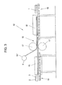
形成された封止材料4は、図3に示されるように装置の給送ローラー13’上に支持される。薄膜太陽電池システム2は、搭載ステーション13において、剛いキャリヤー材料3、例えばガラスと共に輸送ベルト(図示せず)に乗せられて加熱ステーション15に供給される。加熱ステーションにおいて、制御装置の手段(図示せず)により、薄膜太陽電池システム2は、剛いキャリヤー材料3、例えばガラスキャリヤーと共に、封止材料4中のシーリング層5の軟化点まで予熱される。ガラスキャリヤー3と共に70から180℃の温度に予熱された封止材料4及び薄膜太陽電池システム2の両者は、次いでカレンダーローラーの対17の形式の積層ステーション16に供給される。好ましくは70から180℃の範囲の温度に予熱された積層ステーション16における高い温度のため、及びカレンダーローラー17により加えられ好ましくは80から400N/cm(線圧力)の圧力のため、図1に示されたような封止された光起電モジュール1が積層により形成される。これは硬化用オーブン(18)に輸送され、ここで、ほぼ120から190℃の温度で硬化、特にシーリング層5の硬化が生ずる。関連した裁断の後、完成した薄膜モジュール1が排出ステーション19において取り出される。
【0022】
本発明において請求される別の方法が、図4に示された装置を使って詳細に説明される。この場合は、前述の方法と同様に、封止材料4が作られ、給送ローラー13’上に蓄えられる。薄膜太陽電池システム2は、可撓性キャリヤー11と共に別の給送ローラー13’に蓄えられる。
【0023】
可撓性キャリヤー11は、プラスチックフィルム又はプラスチックフィルム複合体とすることができる。例えば、ポリイミドを含んだプラスチックが可撓性キャリヤーに適している。
【0024】
従って、封止材料4と薄膜太陽電池システム2とは、可撓性キャリヤー11と一緒に積層ステーションに供給される。両材料をこのようにすることにより、ウェブは、加熱ステーション23、23’内で、シーリング層5の軟化点、即ちほぼ70から180℃に加熱される。図4に示された積層ステーション21は、例えばカレンダーローラーの対22である。一方又は両方のローラーが、少なくも封止材料4内のシーリング層5の軟化点、好ましくは70から180℃に加熱される。これにより、カレンダーローラーの間隙22’内の予熱された封止材料4が、薄膜太陽電池システム2に直接適用され、そしてこれをほぼ80から400N/cm(線圧力)のローラーの接触圧力で圧縮する。次いで、合成体が、硬化炉24内でほぼ120から190℃の温度で硬化される。この積層段階の手段により薄膜太陽電池システム2が封止され、そして図2に示されるような光起電薄膜モジュール10が形成される。
【0025】
給送ローラー13’の数を増加することにより、追加の封止材料4’の使用が可能となる。薄膜太陽電池システム2について、太陽電池システム2に対する対気象保護又はバリヤ保護に関する更なる改良が確保されるように、図2に従って両側を覆うことも考えられる。
【0026】
纏めると、本発明において請求される方法により、封止材料4及び薄膜太陽電池システム2は、関係のキャリヤーと共に、積層により互いに接合され、圧力と高温の下で圧縮され、複合体の形式の耐候性光起電薄膜モジュールが形成されるということができる。本発明に請求された方法は、公知の方法と比較してプロセス時間及びエネルギー費用が少ないことが特徴である。加えて、容易に実行し得るこの方法において、紫外線、水蒸気及びその他の気象の影響に耐える光起電薄膜モジュールが入手できる。キャリヤー材料、例えばプラスチックフィルム又はプラスチックフィルム複合体の形式の材料を選ぶことにより、光起電モジュールに更に可撓性が与えられる。
【0027】
[商業的適用可能性]
本発明において請求された方法により作られた光起電薄膜モジュールは、太陽光からの電気エネルギー発生に使用される。これらの適用可能性は、非常電話用又はキャンパー用の小型電力設備から、建築物に組み込まれた屋根及び建物前面用のシステムを経て、大きい設備及び太陽光発電所にまで拡張される。
【0028】
戸外の用途においては、蒸気相からPEN又はPETP−PENの共押出し体のキャリヤーフィルム上に堆積された酸化物層により、水蒸気に関する封止材料のバリヤ作用が更に大きくされることが見い出された。
【図面の簡単な説明】
【図1】
本発明において請求された方法を使用して製造された光起電モジュール1であって、剛いキャリヤー材料3、例えば、封止材料として同時に使用されるガラスの上の薄膜太陽電池システム2、及び第2の封止材料4よりなる光起電モジュールの構造を示す。
【図1a】
封止材料4が示され、これはプラスチックシーリング層5及び蒸気相より堆積された無機酸化物層7用のキャリヤー層6、及び耐候性保護層8を含んだバリヤ層9よりなる。
【図2】
本発明において請求された方法により作られた可撓性薄膜モジュール10の構造を示す。この可撓性の特性は、可撓性キャリヤー材料11により作られる。
【図3】
剛い薄膜モジュール1を作るための装置12を示す。
【図4】
可撓性薄膜モジュール10を作るための装置20を示す。
【図5】
SiOxコーティングが設けられた数種のキャリヤーフィルムの水蒸気浸透性を示す。種々のプラスチックがキャリヤーフィルムとして使用され、そして互いに比較される。[0001]
The present invention relates to a method of manufacturing a photovoltaic thin film module having a thin film solar cell system applied to a carrier material and optionally covered on both sides with a sealing material composite.
[0002]
[Prior art]
Photovoltaic cells are used to make electrical energy from sunlight. The energy is preferably produced by a solar cell system made by thin film solar cells. Thin film solar cells can be made from various semiconductor systems such as CIGS (copper-indium-gallium-selenide), CTS (cadmium-tellurium-sulfide), a-Si (amorphous silicon) and others.
[0003]
These thin semiconductor systems are applied to rigid carrier materials such as glass or to flexible carrier materials such as polyimide films, steel strips, metal foils and the like.
[0004]
Thin film solar cells are sensitive to environmental influences such as moisture, oxygen and ultraviolet light. They must be protected against mechanical breakage and in addition must be electrically isolated. Therefore, the thin film solar cell needs to be covered with a sealing material on both sides. The sealing material can be, for example, one or more layers of glass and / or plastic film.
[0005]
A film composite consisting essentially of polyvinyl fluoride (PVF) and polyethylene terephthalate (PETP) is commercially available from the applicant under the name ICOSOLAR and is disclosed in the vacuum lamination method disclosed by WO-Al-94 / 29106. Used to make photovoltaic modules. This known method makes available photovoltaic modules where the solar cell system is satisfactorily protected against environmental influences, but the method itself is combined with a relatively large energy consumption and a long processing time.
[0006]
[Description of invention]
Accordingly, an object of the present invention is to devise a photovoltaic module manufacturing method in which a photovoltaic module is prepared that can be executed with low processing time and low energy cost and has satisfactory weather resistance for outdoor use. That is.
[0007]
As claimed in the present invention, a method of the type mentioned at the outset, wherein in the stacking stage, the sealing layer is adjacent to the thin film solar cell system and the increased pressure and selectively elevated temperature at the stacking station. A material web for an encapsulant composite comprising a protective layer and a sealing layer, and a thin film solar cell system and its carrier material so that a composite for photovoltaic thin film module is formed A web of different materials is brought close together at the laminating station.
[0008]
Advantageous embodiments of the method claimed in the present invention are the subject matter of the dependent claims.
[0009]
[Embodiments of the present invention]
Embodiments of the present invention will be described in detail using the drawings shown in FIGS.
[0010]
The invention will be described in detail using the drawings and examples.
[0011]
In the first production stage, a
[0012]
Examples a) to c) show possible versions for the selection of the material of the respective layers.
[0013]
Example a):
Weatherproof protective layer 8: Polyvinyl chloride (PVF) or polyvinylidene chloride (PVDF) in the form of a film,
Adhesive layer (not shown): polyurethane inorganic oxide layer 7: silicon oxide (SiO x ) or aluminum oxide (Al 2 O 3 )
Weather-resistant protective layer 8: polyurethane or polymethyl methacrylate (PMMA) overcoating and stabilized polyethylene terephthalate film (PETP film)
Adhesive layer (not shown): polyurethane inorganic oxide layer 7: silicon oxide (SiO x ) or aluminum oxide (Al 2 O 3 )
Weather-resistant protective layer 8: Fluoropolymer such as ethylene tetrafluoroethylene copolymer (ETFE), polyvinylidene fluoride (PVDF), polyvinylidene fluoride (PVF), or other fluoropolymer film inorganic oxide layer 7: silicon Oxide (SiO x ) or aluminum oxide (Al 2 O 3 )
Plastic sealing layer 5: In ethylene vinyl acetate (EVA) or ionomer, polymethyl methacrylate (PMMA), polyurethane, polyester or hot melt examples a) to c), the components of the sealing
[0014]
In particular, a fluoropolymer that protects the thin-film
[0015]
The
[0016]
The layer structure with the
[0017]
Since the thin film
[0018]
The formation of the sealing
[0019]
In this context, the
[0020]
Therefore, the weathering layer 8, which can be a plastic film or a plastic film composite, is laminated on the
[0021]
The formed
[0022]
Another method claimed in the present invention is described in detail using the apparatus shown in FIG. In this case, the sealing
[0023]
The
[0024]
Therefore, the sealing
[0025]
Increasing the number of feed rollers 13 'allows the use of additional sealing material 4'. It is also conceivable for the thin-film
[0026]
In summary, according to the method claimed in the present invention, the encapsulating
[0027]
[Commercial applicability]
The photovoltaic thin film module made by the method claimed in the present invention is used to generate electrical energy from sunlight. Their applicability extends from small power facilities for emergency telephones or campers, through roof and building front systems built into buildings, to large facilities and solar power plants.
[0028]
In outdoor applications, it has been found that the barrier action of the sealing material with respect to water vapor is further enhanced by an oxide layer deposited on the carrier film of the coextruded PEN or PETP-PEN from the vapor phase.
[Brief description of the drawings]
[Figure 1]
A
FIG. 1a
A sealing
[Figure 2]
1 shows the structure of a flexible
[Fig. 3]
An
[Fig. 4]
An
[Figure 5]
Shows water vapor permeability of several carrier films SiO x coating is provided. Various plastics are used as carrier films and compared with each other.
Claims (12)
Applications Claiming Priority (3)
| Application Number | Priority Date | Filing Date | Title |
|---|---|---|---|
| AT3872000 | 2000-03-09 | ||
| AT16982000 | 2000-10-05 | ||
| PCT/AT2001/000061 WO2001067523A1 (en) | 2000-03-09 | 2001-03-05 | Method for producing a photovoltaic thin film module |
Publications (1)
| Publication Number | Publication Date |
|---|---|
| JP2005509265A true JP2005509265A (en) | 2005-04-07 |
Family
ID=25608309
Family Applications (1)
| Application Number | Title | Priority Date | Filing Date |
|---|---|---|---|
| JP2001566195A Pending JP2005509265A (en) | 2000-03-09 | 2001-03-05 | Method for producing photovoltaic thin film module |
Country Status (28)
| Country | Link |
|---|---|
| US (1) | US20030029493A1 (en) |
| EP (1) | EP1297577B1 (en) |
| JP (1) | JP2005509265A (en) |
| KR (1) | KR20030028731A (en) |
| CN (1) | CN1418379A (en) |
| AT (1) | ATE407004T1 (en) |
| AU (1) | AU4031501A (en) |
| BG (1) | BG107010A (en) |
| BR (1) | BR0109057A (en) |
| CA (1) | CA2402395A1 (en) |
| CY (1) | CY1108574T1 (en) |
| CZ (1) | CZ20022991A3 (en) |
| DE (1) | DE50114283D1 (en) |
| DK (1) | DK1297577T3 (en) |
| EA (1) | EA200200879A1 (en) |
| EE (1) | EE200200509A (en) |
| ES (1) | ES2310546T3 (en) |
| HU (1) | HUP0300374A2 (en) |
| IL (1) | IL151410A0 (en) |
| MX (1) | MXPA02008674A (en) |
| NO (1) | NO20024280L (en) |
| PL (1) | PL360084A1 (en) |
| PT (1) | PT1297577E (en) |
| SI (1) | SI1297577T1 (en) |
| SK (1) | SK12902002A3 (en) |
| TR (1) | TR200202116T2 (en) |
| WO (1) | WO2001067523A1 (en) |
| YU (1) | YU66802A (en) |
Cited By (1)
| Publication number | Priority date | Publication date | Assignee | Title |
|---|---|---|---|---|
| JP2009502030A (en) * | 2005-07-21 | 2009-01-22 | イソボルタ・アクチエンゲゼルシヤフト | Method for producing weatherable laminate for encapsulation of solar cell system |
Families Citing this family (85)
| Publication number | Priority date | Publication date | Assignee | Title |
|---|---|---|---|---|
| JP2001291881A (en) * | 2000-01-31 | 2001-10-19 | Sanyo Electric Co Ltd | Solar battery module |
| JP3805996B2 (en) * | 2001-04-20 | 2006-08-09 | シャープ株式会社 | Daylighting type laminated glass structure solar cell module and daylighting type multilayer solar cell module |
| DE10164273A1 (en) * | 2001-12-27 | 2003-07-10 | Solarwatt Solar Systeme Gmbh | Flexible planar photovoltaic solar module has solar cells on thin special glass sheet enclosed in water tight plastic foil |
| US20070264564A1 (en) | 2006-03-16 | 2007-11-15 | Infinite Power Solutions, Inc. | Thin film battery on an integrated circuit or circuit board and method thereof |
| US8404376B2 (en) | 2002-08-09 | 2013-03-26 | Infinite Power Solutions, Inc. | Metal film encapsulation |
| US8236443B2 (en) * | 2002-08-09 | 2012-08-07 | Infinite Power Solutions, Inc. | Metal film encapsulation |
| US6916679B2 (en) * | 2002-08-09 | 2005-07-12 | Infinite Power Solutions, Inc. | Methods of and device for encapsulation and termination of electronic devices |
| US8394522B2 (en) | 2002-08-09 | 2013-03-12 | Infinite Power Solutions, Inc. | Robust metal film encapsulation |
| US8431264B2 (en) * | 2002-08-09 | 2013-04-30 | Infinite Power Solutions, Inc. | Hybrid thin-film battery |
| US8021778B2 (en) | 2002-08-09 | 2011-09-20 | Infinite Power Solutions, Inc. | Electrochemical apparatus with barrier layer protected substrate |
| US8535396B2 (en) * | 2002-08-09 | 2013-09-17 | Infinite Power Solutions, Inc. | Electrochemical apparatus with barrier layer protected substrate |
| US8445130B2 (en) * | 2002-08-09 | 2013-05-21 | Infinite Power Solutions, Inc. | Hybrid thin-film battery |
| DE10259472B4 (en) * | 2002-12-19 | 2006-04-20 | Solarion Gmbh | Flexible thin-film solar cell with flexible protective layer |
| US8728285B2 (en) | 2003-05-23 | 2014-05-20 | Demaray, Llc | Transparent conductive oxides |
| US20040244829A1 (en) * | 2003-06-04 | 2004-12-09 | Rearick Brian K. | Coatings for encapsulation of photovoltaic cells |
| US7888584B2 (en) * | 2003-08-29 | 2011-02-15 | Lyden Robert M | Solar cell, module, array, network, and power grid |
| US20050268961A1 (en) * | 2004-06-04 | 2005-12-08 | Saint-Gobain Performance Plastics Coporation | Photovoltaic device and method for manufacturing same |
| US7902452B2 (en) * | 2004-06-17 | 2011-03-08 | E. I. Du Pont De Nemours And Company | Multilayer ionomer films for use as encapsulant layers for photovoltaic cell modules |
| CN100338784C (en) * | 2004-10-12 | 2007-09-19 | 天津大学 | Continuous ion adsorbing preparation of multi-component sulfur photoelectric films |
| US7959769B2 (en) * | 2004-12-08 | 2011-06-14 | Infinite Power Solutions, Inc. | Deposition of LiCoO2 |
| US8636876B2 (en) | 2004-12-08 | 2014-01-28 | R. Ernest Demaray | Deposition of LiCoO2 |
| JP4842923B2 (en) * | 2005-03-08 | 2011-12-21 | 三井・デュポンポリケミカル株式会社 | Solar cell encapsulant |
| DE102006009412A1 (en) | 2006-02-23 | 2007-08-30 | Zentrum für Sonnenenergie- und Wasserstoff-Forschung Baden-Württemberg | Solar modular system has self-supporting support structure, support profile with lateral inserted profile for laterally adding an additional support profile or connecting profile or terminal profile and heat dissipation structure |
| KR100612411B1 (en) * | 2006-03-23 | 2006-08-16 | 류재학 | The method for maunfacturing a solar module |
| US9006563B2 (en) * | 2006-04-13 | 2015-04-14 | Solannex, Inc. | Collector grid and interconnect structures for photovoltaic arrays and modules |
| JP2008004691A (en) * | 2006-06-21 | 2008-01-10 | Toppan Printing Co Ltd | Sheet for sealing backside of solar battery |
| US20100000601A1 (en) * | 2006-08-04 | 2010-01-07 | Arkema France | Photovoltaic modules having a polyvinylidene fluoride surface |
| US8062708B2 (en) * | 2006-09-29 | 2011-11-22 | Infinite Power Solutions, Inc. | Masking of and material constraint for depositing battery layers on flexible substrates |
| US8197781B2 (en) * | 2006-11-07 | 2012-06-12 | Infinite Power Solutions, Inc. | Sputtering target of Li3PO4 and method for producing same |
| DE102007005845A1 (en) * | 2007-02-01 | 2008-08-07 | Kuraray Europe Gmbh | Process for the production of solar modules in the roll composite process |
| AT505186A1 (en) | 2007-05-10 | 2008-11-15 | Isovolta | USE OF A PLASTIC COMPOSITE FOR THE MANUFACTURE OF PHOTOVOLTAIC MODULES |
| JP2010538475A (en) * | 2007-08-31 | 2010-12-09 | アプライド マテリアルズ インコーポレイテッド | Production line module for forming multi-size photovoltaic devices |
| US9334557B2 (en) * | 2007-12-21 | 2016-05-10 | Sapurast Research Llc | Method for sputter targets for electrolyte films |
| US8268488B2 (en) | 2007-12-21 | 2012-09-18 | Infinite Power Solutions, Inc. | Thin film electrolyte for thin film batteries |
| JP5705549B2 (en) | 2008-01-11 | 2015-04-22 | インフィニット パワー ソリューションズ, インコーポレイテッド | Thin film encapsulation for thin film batteries and other devices |
| US20090194156A1 (en) * | 2008-02-01 | 2009-08-06 | Grommesh Robert C | Dual seal photovoltaic glazing assembly and method |
| CN101983469B (en) * | 2008-04-02 | 2014-06-04 | 无穷动力解决方案股份有限公司 | Passive over/under voltage control and protection for energy storage devices associated with energy harvesting |
| WO2009126186A1 (en) | 2008-04-10 | 2009-10-15 | Cardinal Ig Company | Manufacturing of photovoltaic subassemblies |
| US20100144080A1 (en) * | 2008-06-02 | 2010-06-10 | Solexel, Inc. | Method and apparatus to transfer coat uneven surface |
| EP2319101B1 (en) | 2008-08-11 | 2015-11-04 | Sapurast Research LLC | Energy device with integral collector surface for electromagnetic energy harvesting and method thereof |
| JP5650646B2 (en) * | 2008-09-12 | 2015-01-07 | インフィニット パワー ソリューションズ, インコーポレイテッド | Energy device with integral conductive surface for data communication via electromagnetic energy and method for data communication via electromagnetic energy |
| US8508193B2 (en) * | 2008-10-08 | 2013-08-13 | Infinite Power Solutions, Inc. | Environmentally-powered wireless sensor module |
| DE102009000450A1 (en) * | 2009-01-28 | 2010-07-29 | Evonik Degussa Gmbh | Transparent, weather-resistant barrier film, production by lamination, extrusion lamination or extrusion coating |
| KR100913208B1 (en) * | 2009-03-09 | 2009-08-24 | 주식회사 아론 | Bonding device for ribbon on solar cell module |
| DE102009021712A1 (en) | 2009-05-18 | 2010-11-25 | Mitsubishi Polyester Film Gmbh | Coextruded, biaxially oriented polyester films with improved adhesive properties, backside laminates for solar modules and solar modules |
| KR20120025521A (en) * | 2009-05-20 | 2012-03-15 | 인피니트 파워 솔루션스, 인크. | Method of integrating electrochemical devices into and onto fixtures |
| EP2441096B1 (en) * | 2009-06-08 | 2016-03-30 | 3S Swiss Solar Systems AG | Method for producing a solar panel |
| US7888158B1 (en) | 2009-07-21 | 2011-02-15 | Sears Jr James B | System and method for making a photovoltaic unit |
| WO2011019613A1 (en) * | 2009-08-10 | 2011-02-17 | First Solar, Inc. | Lamination process improvement |
| EP2471105A2 (en) * | 2009-08-24 | 2012-07-04 | E. I. du Pont de Nemours and Company | Barrier films for thin-film photovoltaic cells |
| EP2474056B1 (en) * | 2009-09-01 | 2016-05-04 | Sapurast Research LLC | Printed circuit board with integrated thin film battery |
| US20110159280A1 (en) * | 2009-12-31 | 2011-06-30 | Du Pont Apollo Limited | Backsheet for a solar module |
| KR101125184B1 (en) * | 2010-03-02 | 2012-03-21 | 주식회사 에스에프씨 | Preparation Method of Backside Protective Sheet for Solar Cell Module |
| ITRM20100269A1 (en) * | 2010-05-24 | 2010-08-23 | Gianni Quattrini | PLEXIGLASS PHOTOVOLTAIC PANEL |
| ITAN20100087A1 (en) * | 2010-06-01 | 2011-12-02 | Benedetto Carlozzo | PROCEDURE FOR THE REALIZATION OF TRANSPARENT SHEETS IN POLYMETHYLMETHACRYLATE WITH INSIDE PHOTOVOLTAIC FILMS FOR THE PRODUCTION OF SOLAR ENERGY. |
| US20110300432A1 (en) | 2010-06-07 | 2011-12-08 | Snyder Shawn W | Rechargeable, High-Density Electrochemical Device |
| DE102010030074A1 (en) * | 2010-06-15 | 2011-12-15 | Evonik Degussa Gmbh | Plastic photovoltaic module and method for its production |
| US9254506B2 (en) | 2010-07-02 | 2016-02-09 | 3M Innovative Properties Company | Moisture resistant coating for barrier films |
| US9997657B2 (en) | 2010-07-02 | 2018-06-12 | 3M Innovative Properties Company | Barrier assembly |
| US8609980B2 (en) * | 2010-07-30 | 2013-12-17 | E I Du Pont De Nemours And Company | Cross-linkable ionomeric encapsulants for photovoltaic cells |
| US20130203203A1 (en) * | 2010-09-30 | 2013-08-08 | Kiyomi Uenomachi | Manufacturing method for flexible solar cell modules |
| US20130210186A1 (en) * | 2010-11-18 | 2013-08-15 | Sekisui Chemical Co., Ltd. | Method for manufacturing flexible solar cell module |
| US8840308B2 (en) | 2010-11-19 | 2014-09-23 | Saint-Gobain Performance Plastics Corporation | Adhesive film for bushings |
| DE102011050702B4 (en) * | 2011-05-30 | 2018-11-22 | Hanwha Q.CELLS GmbH | Solar module manufacturing method and solar module post-treatment method |
| RU2569086C2 (en) * | 2011-07-26 | 2015-11-20 | Эл Джи Кем, Лтд. | Nanocrystalline layers based on low annealing point titanium dioxide for use in dye-sensitised solar cells and methods for production thereof |
| US20140283910A1 (en) * | 2011-08-04 | 2014-09-25 | 3M Innovative Properties Company | Edge protected barrier assemblies |
| EP2740328A4 (en) * | 2011-08-04 | 2015-05-06 | 3M Innovative Properties Co | Edge protected barrier assemblies |
| WO2013019695A2 (en) * | 2011-08-04 | 2013-02-07 | 3M Innovative Properties Company | Edge protected barrier assemblies |
| CN103165707A (en) * | 2011-12-09 | 2013-06-19 | 纳幕尔杜邦公司 | Crosslinkable edge sealant used for photovoltaic module |
| JP2015513478A (en) * | 2012-02-10 | 2015-05-14 | アーケマ・インコーポレイテッド | Weatherproof composite for flexible thin film photovoltaic and light emitting diode devices |
| DE112013002119T5 (en) * | 2012-04-18 | 2014-12-31 | Guardian Industries Corp. | Improved photovoltaic modules for use in vehicle roofs and / or methods of making same |
| EP2882587A4 (en) | 2012-08-08 | 2016-04-13 | 3M Innovative Properties Co | Barrier film constructions and methods of making same |
| TWI610806B (en) | 2012-08-08 | 2018-01-11 | 3M新設資產公司 | Barrier film, method of making the barrier film, and articles including the barrier film |
| CN103770416A (en) * | 2012-10-24 | 2014-05-07 | 昆山雅森电子材料科技有限公司 | Backboard structure used for solar energy cell module |
| CN104134717B (en) * | 2013-05-02 | 2016-12-28 | 常州亚玛顿股份有限公司 | The manufacture method of solar module |
| PL410124A1 (en) | 2014-11-16 | 2016-05-23 | Marek Adamczewski | Method for producing building element with a photovoltaic cell and the building element with photovoltaic cell |
| WO2017003870A1 (en) | 2015-06-29 | 2017-01-05 | 3M Innovative Properties Company | Ultrathin barrier laminates and devices |
| CN107393987A (en) * | 2016-05-11 | 2017-11-24 | 张家港康得新光电材料有限公司 | Encapsulating material and photoelectric device |
| FR3058832B1 (en) * | 2016-11-14 | 2019-06-14 | Commissariat A L'energie Atomique Et Aux Energies Alternatives | PHOTOVOLTAIC MODULE HAVING AN ADHESION LAYER BETWEEN A PROTECTIVE LAYER AND AN ENCAPSULANT ASSEMBLY |
| CN107386540A (en) * | 2017-07-05 | 2017-11-24 | 林和国 | A kind of photovoltaic polymetal crust material |
| CN107689401A (en) * | 2017-09-14 | 2018-02-13 | 旭科新能源股份有限公司 | A kind of volume to volume package system and method for flexible thin-film solar cell |
| US10840707B2 (en) | 2018-08-06 | 2020-11-17 | Robert M. Lyden | Utility pole with solar modules and wireless device and method of retrofitting existing utility pole |
| US11207988B2 (en) | 2018-08-06 | 2021-12-28 | Robert M. Lyden | Electric or hybrid vehicle with wireless device and method of supplying electromagnetic energy to vehicle |
| US11588421B1 (en) | 2019-08-15 | 2023-02-21 | Robert M. Lyden | Receiver device of energy from the earth and its atmosphere |
| US11784267B2 (en) * | 2019-10-29 | 2023-10-10 | Sun Hunter Inc. | CIGS lamination structure and portable solar charger using same |
Citations (10)
| Publication number | Priority date | Publication date | Assignee | Title |
|---|---|---|---|---|
| JPH04239634A (en) * | 1991-01-24 | 1992-08-27 | Mitsubishi Kasei Polytec Co | Weather-resistant transparent laminated film |
| JPH06503684A (en) * | 1990-11-30 | 1994-04-21 | ユナイテッド ソーラー システムズ コーポレイション | Photovoltaic roof and its manufacturing method |
| JPH07193266A (en) * | 1993-12-27 | 1995-07-28 | Canon Inc | Manufacture of solar battery module |
| JPH08500214A (en) * | 1993-06-11 | 1996-01-09 | イソボルタ・エスターライヒツシエ・イゾリールシユトツフベルケ・アクチエンゲゼルシヤフト | Photovoltaic module manufacturing method and apparatus for implementing this method |
| JPH0864852A (en) * | 1994-08-18 | 1996-03-08 | Fuji Electric Corp Res & Dev Ltd | Manufacture of solar light power generation roof material |
| JPH08267637A (en) * | 1995-03-31 | 1996-10-15 | Toppan Printing Co Ltd | Barrier material with vepor deposition layer and laminated material using this barrier material |
| JPH09153631A (en) * | 1995-11-30 | 1997-06-10 | Fuji Electric Co Ltd | Manufacture of flexible solar battery |
| JPH1025357A (en) * | 1996-07-12 | 1998-01-27 | Dainippon Printing Co Ltd | Transparent and composite film |
| JPH1065194A (en) * | 1996-08-20 | 1998-03-06 | Fuji Electric Co Ltd | Roll-type manufacturing method and device for solar cell module |
| WO2000002257A1 (en) * | 1998-07-03 | 2000-01-13 | ISOVOLTA Österreichische Isolierstoffwerke Aktiengesellschaft | Photovoltaic module and method for producing same |
Family Cites Families (7)
| Publication number | Priority date | Publication date | Assignee | Title |
|---|---|---|---|---|
| US3616130A (en) * | 1967-09-27 | 1971-10-26 | Ethyl Corp | Reinforced plastic material |
| US3745140A (en) * | 1971-09-22 | 1973-07-10 | Allied Chem | Shapable fiber-reinforced novaculitefilled low molecular weight polyethylene terephthalate |
| US4410558A (en) * | 1980-05-19 | 1983-10-18 | Energy Conversion Devices, Inc. | Continuous amorphous solar cell production system |
| JPS5961077A (en) * | 1982-09-29 | 1984-04-07 | Nippon Denso Co Ltd | Amorphous silicon solar battery |
| US5273608A (en) * | 1990-11-29 | 1993-12-28 | United Solar Systems Corporation | Method of encapsulating a photovoltaic device |
| US6335479B1 (en) * | 1998-10-13 | 2002-01-01 | Dai Nippon Printing Co., Ltd. | Protective sheet for solar battery module, method of fabricating the same and solar battery module |
| AU2001262717A1 (en) * | 2000-07-03 | 2002-01-14 | Bridgestone Corporation | Backside covering material for a solar cell module and its use |
-
2001
- 2001-03-05 DE DE50114283T patent/DE50114283D1/en not_active Expired - Lifetime
- 2001-03-05 TR TR2002/02116T patent/TR200202116T2/en unknown
- 2001-03-05 SI SI200130885T patent/SI1297577T1/en unknown
- 2001-03-05 PT PT01911230T patent/PT1297577E/en unknown
- 2001-03-05 EP EP01911230A patent/EP1297577B1/en not_active Expired - Lifetime
- 2001-03-05 JP JP2001566195A patent/JP2005509265A/en active Pending
- 2001-03-05 IL IL15141001A patent/IL151410A0/en unknown
- 2001-03-05 KR KR1020027011765A patent/KR20030028731A/en not_active Application Discontinuation
- 2001-03-05 CA CA002402395A patent/CA2402395A1/en not_active Abandoned
- 2001-03-05 HU HU0300374A patent/HUP0300374A2/en unknown
- 2001-03-05 SK SK1290-2002A patent/SK12902002A3/en unknown
- 2001-03-05 YU YU66802A patent/YU66802A/en unknown
- 2001-03-05 MX MXPA02008674A patent/MXPA02008674A/en unknown
- 2001-03-05 BR BR0109057-7A patent/BR0109057A/en active Pending
- 2001-03-05 EA EA200200879A patent/EA200200879A1/en unknown
- 2001-03-05 DK DK01911230T patent/DK1297577T3/en active
- 2001-03-05 WO PCT/AT2001/000061 patent/WO2001067523A1/en active IP Right Grant
- 2001-03-05 ES ES01911230T patent/ES2310546T3/en not_active Expired - Lifetime
- 2001-03-05 AU AU40315/01A patent/AU4031501A/en not_active Abandoned
- 2001-03-05 EE EEP200200509A patent/EE200200509A/en unknown
- 2001-03-05 PL PL36008401A patent/PL360084A1/en unknown
- 2001-03-05 AT AT01911230T patent/ATE407004T1/en active
- 2001-03-05 CN CN01806288A patent/CN1418379A/en active Pending
- 2001-03-05 US US10/221,028 patent/US20030029493A1/en not_active Abandoned
- 2001-03-05 CZ CZ20022991A patent/CZ20022991A3/en unknown
-
2002
- 2002-08-16 BG BG107010A patent/BG107010A/en unknown
- 2002-09-06 NO NO20024280A patent/NO20024280L/en not_active Application Discontinuation
-
2008
- 2008-11-19 CY CY20081101323T patent/CY1108574T1/en unknown
Patent Citations (10)
| Publication number | Priority date | Publication date | Assignee | Title |
|---|---|---|---|---|
| JPH06503684A (en) * | 1990-11-30 | 1994-04-21 | ユナイテッド ソーラー システムズ コーポレイション | Photovoltaic roof and its manufacturing method |
| JPH04239634A (en) * | 1991-01-24 | 1992-08-27 | Mitsubishi Kasei Polytec Co | Weather-resistant transparent laminated film |
| JPH08500214A (en) * | 1993-06-11 | 1996-01-09 | イソボルタ・エスターライヒツシエ・イゾリールシユトツフベルケ・アクチエンゲゼルシヤフト | Photovoltaic module manufacturing method and apparatus for implementing this method |
| JPH07193266A (en) * | 1993-12-27 | 1995-07-28 | Canon Inc | Manufacture of solar battery module |
| JPH0864852A (en) * | 1994-08-18 | 1996-03-08 | Fuji Electric Corp Res & Dev Ltd | Manufacture of solar light power generation roof material |
| JPH08267637A (en) * | 1995-03-31 | 1996-10-15 | Toppan Printing Co Ltd | Barrier material with vepor deposition layer and laminated material using this barrier material |
| JPH09153631A (en) * | 1995-11-30 | 1997-06-10 | Fuji Electric Co Ltd | Manufacture of flexible solar battery |
| JPH1025357A (en) * | 1996-07-12 | 1998-01-27 | Dainippon Printing Co Ltd | Transparent and composite film |
| JPH1065194A (en) * | 1996-08-20 | 1998-03-06 | Fuji Electric Co Ltd | Roll-type manufacturing method and device for solar cell module |
| WO2000002257A1 (en) * | 1998-07-03 | 2000-01-13 | ISOVOLTA Österreichische Isolierstoffwerke Aktiengesellschaft | Photovoltaic module and method for producing same |
Cited By (1)
| Publication number | Priority date | Publication date | Assignee | Title |
|---|---|---|---|---|
| JP2009502030A (en) * | 2005-07-21 | 2009-01-22 | イソボルタ・アクチエンゲゼルシヤフト | Method for producing weatherable laminate for encapsulation of solar cell system |
Also Published As
| Publication number | Publication date |
|---|---|
| YU66802A (en) | 2004-03-12 |
| DK1297577T3 (en) | 2009-01-05 |
| CN1418379A (en) | 2003-05-14 |
| ATE407004T1 (en) | 2008-09-15 |
| CZ20022991A3 (en) | 2003-02-12 |
| KR20030028731A (en) | 2003-04-10 |
| AU4031501A (en) | 2001-09-17 |
| EP1297577B1 (en) | 2008-09-03 |
| ES2310546T3 (en) | 2009-01-16 |
| PL360084A1 (en) | 2004-09-06 |
| BG107010A (en) | 2003-03-31 |
| WO2001067523A1 (en) | 2001-09-13 |
| NO20024280L (en) | 2002-10-06 |
| BR0109057A (en) | 2003-06-03 |
| EP1297577A1 (en) | 2003-04-02 |
| EA200200879A1 (en) | 2003-02-27 |
| SK12902002A3 (en) | 2003-05-02 |
| US20030029493A1 (en) | 2003-02-13 |
| SI1297577T1 (en) | 2009-02-28 |
| CA2402395A1 (en) | 2001-09-13 |
| DE50114283D1 (en) | 2008-10-16 |
| TR200202116T2 (en) | 2003-03-21 |
| MXPA02008674A (en) | 2004-09-06 |
| CY1108574T1 (en) | 2013-03-13 |
| HUP0300374A2 (en) | 2003-07-28 |
| EE200200509A (en) | 2004-04-15 |
| PT1297577E (en) | 2008-10-14 |
| IL151410A0 (en) | 2003-04-10 |
| NO20024280D0 (en) | 2002-09-06 |
Similar Documents
| Publication | Publication Date | Title |
|---|---|---|
| JP2005509265A (en) | Method for producing photovoltaic thin film module | |
| US8318316B2 (en) | Use of a polymer composite for the production of photovoltaic modules | |
| CA2300828C (en) | Photovoltaic module and a procedure for its manufacture | |
| US20100200063A1 (en) | Thin film solar cell | |
| CN101203379A (en) | Method for producing weather-resistant laminates for encapsulating solar cell systems | |
| EP0551377B1 (en) | Method of laminating composite structures for photovoltaic devices | |
| WO2010090642A1 (en) | Thin film solar cell | |
| WO2010021614A1 (en) | Thin film solar cell | |
| US20210367088A1 (en) | Photovoltaic building element | |
| ZA200206743B (en) | Method for producing a photovoltaic thin film module. | |
| CN102265409A (en) | Solar cell module | |
| JP2004186549A (en) | Method for manufacturing solar battery module | |
| KR20230052833A (en) | Rollable solar cell module and method of febricating the same | |
| JP2006202807A (en) | Solar cell module and its manufacturing process | |
| MXPA00001946A (en) | Photovoltaic module and method for producing same |
Legal Events
| Date | Code | Title | Description |
|---|---|---|---|
| A621 | Written request for application examination |
Free format text: JAPANESE INTERMEDIATE CODE: A621 Effective date: 20071220 |
|
| RD02 | Notification of acceptance of power of attorney |
Free format text: JAPANESE INTERMEDIATE CODE: A7422 Effective date: 20081110 |
|
| A977 | Report on retrieval |
Free format text: JAPANESE INTERMEDIATE CODE: A971007 Effective date: 20100902 |
|
| A131 | Notification of reasons for refusal |
Free format text: JAPANESE INTERMEDIATE CODE: A131 Effective date: 20100914 |
|
| A601 | Written request for extension of time |
Free format text: JAPANESE INTERMEDIATE CODE: A601 Effective date: 20101210 |
|
| A602 | Written permission of extension of time |
Free format text: JAPANESE INTERMEDIATE CODE: A602 Effective date: 20101217 |
|
| A711 | Notification of change in applicant |
Free format text: JAPANESE INTERMEDIATE CODE: A711 Effective date: 20110104 |
|
| A131 | Notification of reasons for refusal |
Free format text: JAPANESE INTERMEDIATE CODE: A131 Effective date: 20111220 |
|
| A521 | Request for written amendment filed |
Free format text: JAPANESE INTERMEDIATE CODE: A523 Effective date: 20120314 |
|
| A02 | Decision of refusal |
Free format text: JAPANESE INTERMEDIATE CODE: A02 Effective date: 20121002 |