JP2005507799A - Image forming apparatus having position detection device - Google Patents
Image forming apparatus having position detection device Download PDFInfo
- Publication number
- JP2005507799A JP2005507799A JP2003539950A JP2003539950A JP2005507799A JP 2005507799 A JP2005507799 A JP 2005507799A JP 2003539950 A JP2003539950 A JP 2003539950A JP 2003539950 A JP2003539950 A JP 2003539950A JP 2005507799 A JP2005507799 A JP 2005507799A
- Authority
- JP
- Japan
- Prior art keywords
- printing device
- image forming
- forming apparatus
- sensor
- movable
- Prior art date
- Legal status (The legal status is an assumption and is not a legal conclusion. Google has not performed a legal analysis and makes no representation as to the accuracy of the status listed.)
- Pending
Links
Images

Classifications
-
- B—PERFORMING OPERATIONS; TRANSPORTING
- B41—PRINTING; LINING MACHINES; TYPEWRITERS; STAMPS
- B41J—TYPEWRITERS; SELECTIVE PRINTING MECHANISMS, i.e. MECHANISMS PRINTING OTHERWISE THAN FROM A FORME; CORRECTION OF TYPOGRAPHICAL ERRORS
- B41J19/00—Character- or line-spacing mechanisms
- B41J19/18—Character-spacing or back-spacing mechanisms; Carriage return or release devices therefor
- B41J19/20—Positive-feed character-spacing mechanisms
- B41J19/202—Drive control means for carriage movement
- B41J19/205—Position or speed detectors therefor
- B41J19/207—Encoding along a bar
Abstract
可動プリントデバイス(104、158、158’、170、176、184)上の少なくとも2つの場所の位置を別個に検出する位置検出デバイス(108、108a、108b、110a、110b、180a、180b、182a、182b)を有する画像形成装置(100)。Position detection devices (108, 108a, 108b, 110a, 110b, 180a, 180b, 182a, which separately detect the position of at least two locations on the movable printing device (104, 158, 158 ′, 170, 176, 184), 182b) an image forming apparatus (100).
Description
【技術分野】
【0001】
本開示は画像形成装置に関し、詳細には、位置検出デバイスを有する画像形成装置に関する。
【背景技術】
【0002】
画像形成装置は、紙、カード、マイラー、および透明シートのスタックを含むがこれに限定するものではないさまざまなプリント媒体上に、テキストおよびグラフィック画像を形成するのに用いられる。画像形成装置には、走査キャリッジと1つまたはそれよりも多くのプリント素子とからなるプリントデバイスを含むものもある。画像形成動作中、走査キャリッジは、プリント媒体表面の上を走査軸に沿って左右に横切る。走査キャリッジが左右に横切る間、コントローラがプリント素子(複数可)に、所望の画像の各部分になることが意図される各位置において、プリントを行わせる。プリント媒体は、定期的に、走査キャリッジが動く軸を横断する媒体軸に沿って前進して、画像が完成するようにする。
【0003】
インクジェットプリンタは、このタイプのプリントデバイスを有する画像形成装置の一例である。ここでは、走査キャリッジは1つまたはそれよりも多くのインクジェットペンを保持している。ペンは、キャリッジが媒体を横切って走査する間に個々のインクスポット(すなわち「滴」)をプリントする、行および列からなる二次元のアレイになるように配置した複数のインク噴射ノズルを有する、プリントヘッドを含むことが多い。例えば、スウォースが1/2インチで600dpi(1インチ当たり600ドット)のプリントヘッドであれば、通常列を2つ有し、それぞれの列に150個のノズルがある。圧電または熱の噴射機構等のインク噴射機構によって、ノズルを通してインク滴が発射され、所望のドットパターン(すなわち「画像」)を作成する。
【0004】
キャリッジが保持しているプリント素子のタイプにかかわらず、走査軸に沿って走査キャリッジが動く間にプリント素子の位置を正確に追跡することができるということが、通常重要である。プリントプロセスをより正確に制御し、ドット配置誤差およびその他のプリント誤差を減らすのに、位置データを用いるからである。この目的のために、リニア・エンコーダ・ストリップとセンサとの構成を用いることが多い。一連の目盛りを含むエンコーダ・ストリップが、走査軸と平行に搭載され、光源と検出器等からなるセンサが、エンコーダ・ストリップの近傍に、キャリッジによって保持される。エンコーダ・ストリップとセンサとの仕組みからの位置情報を用いて、プリント素子の作動を、そしてインクジェットプリンタのペンの場合には、ペン上の個々のノズルの発射を制御する。位置情報はまた、キャリッジの動きを制御するのに用いてもよい。
【0005】
従来のエンコーダ・ストリップとセンサとの仕組みの精度は、センサとプリント素子との間の距離が大きくなるにつれて下がる。プリント動作中、プリント素子とセンサとの相対位置は一定のままではないからである。これは、通常走査キャリッジを支持する軸受にいくらか「傾き」があり、また、キャリッジが走査軸に沿って動く間にキャリッジがいくらかたわむ、という事実のためである。複数のペンを有するインクジェットプリンタ等の、プリント素子が多数の画像形成装置においては、プリント素子のうちのいくつかとセンサとの間の距離が比較的大きくなってしまう可能性があり、それが、ドット配置誤差の可能性を高くしてしまうことで、そのようなプリント素子の位置精度に悪影響を与える。比較的高さのあるスウォースをプリントする、比較的高さのあるプリント素子(すなわち、媒体軸に沿って長くなっている)を用いる場合にも、同じ問題に遭遇する可能性がある。ここで、センサと、比較的高さのあるプリント素子のうちのいくらかの部分との間に十分大きい距離がある結果として、そのような部分およびドット配置についての位置データが誤ってしまったり、その他のプリント誤差が生じてしまう可能性がある。
【発明の開示】
【0006】
本発明の一実施形態によれば、可動プリントデバイス上の少なくとも2つの場所の位置を検出する装置を提供することができる。
【発明を実施するための最良の形態】
【0007】
添付図面を参照して、本発明の好ましい実施形態の詳細な説明を行う。
【0008】
以下は、本発明を実施する、現在知られている最良の態様の詳細な説明である。この説明は、限定する意味で解釈してはならず、単に本発明の一般的な原理を説明する目的で行う。さらに、画像処理システム、プリント制御システム、およびホストコンピュータとのやりとり、の具体的詳細等、本発明に関係しない画像形成装置のさまざまな内部動作構成要素の詳細な説明は、簡単のために省かれている、ということに注意されたい。
【0009】
本発明はいかなる特定の画像形成装置にも限定されないが、例示的実施形態は、大判インクジェットプリンタの状況において説明する。本明細書における発明者らは、本発明を実施する、組み込む、または行うような方法で再構成することができる、従来の大判プリンタの一例は、ヒューレット・パッカードのDesignJet2500シリーズのプリンタのうちの1つである、と確認している。本発明を適用することができる画像形成装置の他の例は、インパクトプリンタである。
【0010】
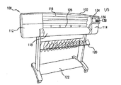
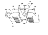
例えば図1および図2において示すように、本発明の一実施形態による画像形成装置100は、ハウジング102と可動プリントデバイス104とを含む。プリントデバイス104の位置は、センサシステム106によって監視される。センサシステム106は、好ましくは、目に見える目盛りのついたエンコーダ・ストリップ108等の、検出可能なしるしを有するデバイスと、少なくとも2つのセンサ110a、110bとを含む。センサシステム106については、以下でより詳細に説明する。例示的ハウジング102には、端部112、114、窓116、プリント媒体のロール(図示せず)を覆うカバー118、受取ビン120、および棚122が設けられている。ハウジング端部112には、好ましくは走査モータ124と複数のペン補充ステーション(図示せず)とが納めてあり、走査モータ124は、プリント媒体126の上でプリントデバイス104を左右に駆動する。プリント媒体126は、スロット128を通って取り出され、ローラ130によって運ばれる。ローラ130は、従来の方法でモータ132によって駆動される。ハウジング端部114内には、モータ132とプリント素子クリーニングステーション(図示せず)とが配置されている。ハウジング端部114の外面上には、好ましくは、ディスプレイ136とコントロールボタン138とを含む制御パネル134が支持されている。
【0011】
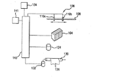
例示的実施形態において、プリントデバイス104、センサシステム106、モータ124、132、および制御パネル134は、従来の方法でプリンタコントローラ140に接続されている。好適なプリンタコントローラには、例えば、マイクロプロセッサをベースにしたコントローラが含まれる。コントローラ140にはクロック141が時間情報を提供する。この時間情報は、センサシステム106からの位置情報と組み合わせると、プリントデバイス104の速度および加速度を計算するのに用いることができ、次にこの速度および加速度を、プリントデバイスの動作を制御するときにコントローラが用いることができる。一般的に、プリンタコントローラ140は、プリントデバイス104およびモータ124、132の動作を制御するときに、画像データを例えばアプリケーションプログラムから受け取り、位置データをセンサシステム106から受け取り、時間情報をクロック141から受け取って、画像データに対応する画像を生成する。例示的プリンタコントローラ140の動作のさらなる態様については、以下により詳細に説明する。
【0012】
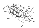
図3を参照して、例示的画像形成装置100におけるプリントデバイス104は、複数のプリント素子を含む。好ましくは、プリントデバイス104には、複数のインクジェットペン142(「プリントヘッドカートリッジ」、「ペンカートリッジ」、および「プリントカートリッジ」と呼ぶこともある)が設けられており、ペン142は、本明細書において「バンク」と呼ぶ配列になるように、走査キャリッジ144によって保持されている。ペン142は、例えば、少量のインクを保持し遠く離れたインク槽にペンを接続する管によって補充されるタイプ(「軸外」のシステムと呼ぶこともあるものにおいて)、または、遠く離れたインク槽に周期的に移動して、そこで充填されるタイプ(「飲み込み)」システムと呼ぶこともあるものにおいて)の、内蔵型インク槽を含む、容易に着脱可能なタイプであってもよい。前述のヒューレット・パッカードのDesignJet2500シリーズのプリンタ等、大判プリンタ用の、ヒューレット・パッカードのモデル番号C1806Aのペンは、例示的実施形態において用いるのに好適なペンである。そのようなペンは、124個のノズルを2列(全部で248個のノズル)有するノズル板143(図5)を含む。
【0013】
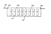
ペン142の数、ペンバンクの数、およびバンク(複数可)内でのペンの配列は、特定の用途に適合するようさまざまであってもよいが、図1〜図4に示す例示的実施形態は、単一のバンク内に8個のペンを含む。しかし、単一のバンク内でのペン142の数は、1個から12個まで変化してもよく、用途が要求するならば、さらに多くてもよい。各バンクは、それぞれのペンが他のペンと整列するように(図示のように)配置してもよく、または、媒体軸に沿って、そのバンク内の1つまたはそれよりも多くのペンが、1つまたはそれよりも多くの残りのペンとオフセットしている(すなわち「千鳥配置」である)ように配置してもよい。さらに、ペン142は、ノズル列が媒体走査軸と平行であるように配置してもよく、ノズル列が媒体走査軸に関して斜めであるように配置してもよい。
【0014】
滑り軸受上を摺動ロッド146a、146b(図3)に沿って左右に往復して摺動(すなわち走査)してキャリッジ走査軸を画定する例示的走査キャリッジ144は、主に、それぞれペン142を収容する複数のペンスロット149を有する本体148からなっている。枢転可能なラッチ150を用いて、ペン142を所定位置に保持してもよい。後部トレイ152は、ペンインターフェースプリント回路基板等の電子デバイスを保持している。このような電子デバイスはまた、縦またはその他の向きに搭載してもよい。例示的実施形態において、走査モータ124は、駆動ベルト154によって従来の方法で走査キャリッジ144に接続されている。必要に応じ、モータとケーブルとの構成またはリニアモータ等、走査キャリッジを駆動する他の機構を用いてもよい。
【0015】
上述のように、および例えば図2〜図4に示すように、例示的画像形成装置100は、透明なリニア・エンコーダ・ストリップ108と1対のセンサ110a、110bからなるセンサシステム106を含む。すなわち、走査キャリッジ144が動くときに目盛りを検出して、走査軸上での走査キャリッジの位置を求める。好適なセンサは、従来の光源と光センサからなる装置である。この装置においては、光源からの光は、エンコーダ・ストリップを通るように向けられ、エンコーダ・ストリップの他方の側にあるセンサがこれを検出する。走査キャリッジ144がそのホーム・ロケーションから離れて動くときに検出する目盛りの数をベースにした位置データを用いて、走査キャリッジ144がプリント媒体126の上を通過する毎に、その間のペンのノズルの発射回数(すなわち、ノズルがインクを噴射する回数)を求める。好ましくは、センサ110a、110bは、走査キャリッジ144の長手方向両端のそれぞれのセンサのハウジング156(一方のみが見える)内(図3を参照)に、隣接するペン142に実現可能な限り接近して配置される。一実施形態において、センサ110aからのデータを用いて、4つの最も接近したペン142、すなわち図4において「A」で識別するもののノズル発射回数を制御し、センサ110bからのデータを用いて、残りの4つのペン、すなわち「B」で識別するもののノズル発射回数を制御する。キャリッジの動きを制御する目的で、センサ110a、110bのどちらか一方からの位置データを、クロック141からの時間情報とともに従来の方法で用いてもよい。
【0016】
他の実施形態において、センサ110aからのデータとセンサ110bからのデータとが組み合わされ、コントローラ140が、センサ同士の間(またはセンサの外側)にある場所についての位置データを内挿補間する(そして、必要ならば外挿補間する)。それぞれのペン142の場所についての位置データが内挿補間され、それを用いて各ペンの発射を個々に制御する。
【0017】
用いる走査キャリッジの構成およびその他製造上の制約によるが、各センサと、関連するペン142またはその他のプリント素子との間の距離をさらに小さくするために、センサ110a、110bを再配置してもよい。例えば、センサ110a、110bを、図4に示す破線位置まで動かしてもよい。さらに、センサ110aおよび/または110bの数もまた、関連する走査キャリッジの構成、ペン(またはその他のプリント素子)の大きさ、数、およびタイプ、ならびに、例えばドット配置誤差で測る、プリント精度の所望のレベル次第で、さまざまであってもよい。用途が要求するならば、それぞれのペンが対応するセンサを有しさえしてもよく、または、図8を参照して後述するように、単一のペンが、関連する、1つよりも多いセンサを有してもよい。
【0018】
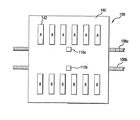
本発明は、図1〜図4に示す例示的画像形成装置に限定されるものではない。次に図5および図6を参照して、他の好ましい実施形態によるプリントデバイス158は、ノズル板開口部を有する2つのペンスロットバンクを含む。ノズル板開口部によって、ノズル板143がプリント媒体に対峙することができる。プリントデバイス158は、モータとベルトとの仕組みによって、上述の方法で、プリント媒体の上を左右に往復して駆動されてもよい。ペン142は、走査キャリッジ160上に支持される。例示的実施形態において、走査キャリッジ160は、6個のペンスロットからなる2つのバンクと、1対の滑り軸受164a、164bとを有する、本体162を含む。1対の滑り軸受164a、164bによって、キャリッジが、1対のレール(図示せず)に沿って摺動することができる。2つのペンインターフェースプリント回路基板166a、166b、すなわち、それぞれのペンバンクに1つずつ、もまた設けられている。
【0019】
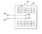
キャリッジ、したがってペン位置の検出に関して、図5および図6に示す例示的実施形態における走査キャリッジ160は、好ましくは、少なくとも2つのエンコーダ・ストリップ108a、108bと少なくとも2つのセンサ110a、110bとを有する、センサシステムを含む、画像形成装置において用いられる。その目的のために、エンコーダ・ストリップ108a、108bは、ペンバンクに隣接して配置された1対のセンサのハウジング168a、168bを通っている。センサ110aからのデータを用いて、図6において「A」で識別されるペン142のノズル発射回数を制御し、センサ110bからのデータを用いて、「B」で識別されるペンのノズル発射回数を制御する。
【0020】
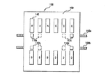
センサ110a、110bは、好ましくは、センサと、センサから最も遠いペンとの間の距離を最小限にするために、ペン142のそれぞれのバンクの中央に配置される。または、例えば図7に示すように、ドット配置の精度をさらに上げるために、4つのセンサ110a、110b、110c、110dを、その他の点ではプリントデバイス158と同一のプリントデバイス158’に設ける。センサ110aからのデータを用いて、「A」で識別されるペン142のノズル発射回数を制御し、センサ110bからのデータを用いて、「B」で識別されるペンのノズル発射回数を制御し、センサ110cからのデータを用いて、「C」で識別されるペン142のノズル発射回数を制御し、センサ110dからのデータを用いて、「D」で識別されるペンのノズル発射回数を制御する。あるいは、走査キャリッジの構成および製造上の制約を考えて可能であれば、センサ110a、110b、110c、110dを図7の破線で示す位置に配置してもよい。
【0021】
本発明はまた、比較的高さのあるスウォースをプリントすることができるプリントデバイスが用いられている画像形成装置にも適用可能である。例えば図8に示すように、例示的プリントデバイス170は、キャリッジ174上に1つまたはそれよりも多くのペン172またはその他のプリント素子を含んでもよい。ペン172は、比較的高さがあり、比較的高さのあるスウォース(すなわち、通常1インチよりも高い)をプリントする。センサシステムと、比較的高さのあるペン172の個々のノズルとの間の距離を小さくするために、例示的プリントデバイス170は、少なくとも2つのエンコーダ・ストリップ108a、108bと少なくとも2つのセンサ110a、110bとからなるセンサシステムを含む。エンコーダ・ストリップ108a、108bは、1対のセンサのハウジングを通っている。1対のセンサのハウジングは、図5に関して上述したものと同様であり、ペンバンクの中央線に隣接して配置されている。しかし、ここでは、センサ110a、110bは、特定のペンではなく、特定のノズルに関連している。すなわち、センサ110aからのデータを用いて、ペン172のうちの「A」で識別される部分のノズルの発射回数を制御し、センサ110bからのデータを用いて、ペンのうちの「B」で識別される部分のノズルの発射回数を制御する。
【0022】
本発明の他の実施態様において、エンコーダをベースにしたセンサシステム以外のデバイスを用いて、可動プリントデバイス上の2つまたはそれよりも多くの場所の位置を監視してもよい。ここで、画像形成装置内に1つまたはそれよりも多くのセンサデバイスが設けられ、プリントデバイス上の1つまたはそれよりも多くの基準点が、プリントデバイス上の2つの異なる場所における位置の検出を容易にする。基準点は、プリントデバイス上に配置されたさらなるデバイス(すなわち、「協同する素子」)であってもよく、光沢のあるブラケット等、プリントデバイス自体のうちの容易に識別可能な部分であってもよい。
【0023】
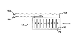
例えば図9に示すように、例示的プリントデバイス176は、キャリッジ178上に1つまたはそれよりも多くのペン142またはその他のプリント素子を含んでもよい。プリントデバイス176の動きは、レーザー干渉計システムによって検出される。ここで、レーザー干渉計システムは、関連するプリント装置内の、好ましく走査軸の一端に搭載された、1対の光源およびセンサのデバイス180a、180bと、キャリッジ178上に互いに間隔を置いた関係になるように保持されて基準点の役割を果たす、好ましくは鏡である1対の反射体182a、182bとを含む。反射体182a、182bは、キャリッジ178の頂部、底部、または側面に配置してもよい。発信源およびセンサのデバイス180a、180bが発する、可視スペクトル内と外の両方のすべての好適な電磁エネルギーを含む光ビームが、反射体182a、182bによって反射されて、図9に示す方法で源およびセンサのデバイスに戻り、反射体がそれぞれの元の原点から移動した距離を個々に求める。センサ180aからのデータを用いて、「A」で識別されるペン142のノズル発射回数を制御し、センサ180bからのデータを用いて、「B」で識別されるペンのノズル発射回数を制御する。
【0024】
用途によって必要な場合は、さらなる発信源およびセンサのデバイスならびに反射体を設けてもよい。さらに、個々の発信源およびセンサのデバイス180a、180bは、1つよりも多くの光ビームを提供し検出することができる単一のデバイスに組み込んでもよく、個々の互いに間隔を置いて配置した反射体182a、182bを、プリントデバイス上の2つの異なる場所からの光を反射することができる単一の構成要素内に組み込んでもよい。
【0025】
図9に関して上述したレーザー干渉計センサシステムは、その他のセンサシステムの代わりに、またはそれと組み合わせて、本明細書において開示するプリントデバイスのうちのいずれに組み込まれてもよい。例えば、図10に示すプリントデバイス184は、6つのペン142からなる2つのバンクを支持する、キャリッジ186を含む。ここでもまた、関連するプリント装置内に1対の光源およびセンサのデバイス180a、180bが搭載されており、1対の反射体182a、182bが、互いに間隔をおいた関係になるようにキャリッジ186上に保持されている。センサ180aからのデータを用いて、「A」で識別されるペン142のノズル発射回数を制御し、センサ180bからのデータを用いて、「B」で識別されるペンのノズル発射回数を制御する。
【0026】
本装置および方法は、従来の装置および方法よりも優れた多数の利点を提供する。例えば、可動プリントデバイス上の1つよりも多くの場所において位置データを取得することによって、プリントデバイスのそれぞれの部分と関連するセンサとの間の距離が小さくなり、それによって、プリントデバイスの精度が上がり、ドット配置またはその他の誤差の可能性が低くなる。可動プリントデバイス上の1つよりも多くの場所において位置データを取得することによってまた、より低公差、低コスト材料、および/または簡単な製造プロセスで製造されるプリントデバイスが、より厳しい公差、高コスト材料、および/または複雑な製造プロセスで製造されるものと同じドット配置の精度を達成することもできる。さらに、万一個々の位置検出サブシステムが故障した場合には、1つまたはそれよりも多くの他の位置検出サブシステムからの位置データを用いて、性能のレベルは下がるとはいえ、動作を継続することができる。
【0027】
本発明を上記の好ましい実施形態に関して説明したが、当業者には、上述の好ましい実施形態への多数の変更および/または付け加えが容易に明白であろう。
【0028】
限定としてではなく例として、図8に関して上述した比較的高さのあるペンの代わりに、2つまたはそれよりも多くのペンまたはその他のプリント素子の端と端が接した状態で整列するプリントデバイスを用いて、比較的高さのあるスウォースを形成してもよい。本実施形態はまた、上述したものの他に、幅広くさまざまなセンサとともに用いることもでき、エンコーダをベースにしたシステムおよびレーザー干渉計システムに限定されるものではない。他の好適なセンサシステムとしては、光反射型エンコーダ・ストリップシステム、磁気エンコーダ・ストリップシステム、三角測量センサシステム、磁気ひずみセンサシステム、超音波センサシステム、ケーブル延長トランスデューサシステム、線形可変差動変圧器システム、およびデジタルカメラシステムが含まれる。さらに、センサおよび/または基準点は、キャリッジが保持する代わりに、ペン自体のうちのいくつかまたはすべてが保持してもよい。
【0029】
一般的に、本開示は、可動プリントデバイス上の少なくとも2つの場所の位置を別個に検出する位置検出デバイスを有する画像形成装置を明らかにした。
【0030】
本発明の範囲は、そのような変更および/または付け加えのすべてに及ぶ、ということが意図される。
【図面の簡単な説明】
【0031】
【図1】本発明の好ましい実施形態による画像形成装置の斜視図である。
【図2】図1に示す画像形成装置の概略ブロック図である。
【図3】本発明の一実施形態によるプリントデバイスの斜視図である。
【図4】本発明の好ましい実施形態による、プリントデバイスとセンサとのシステムの概略ブロック図である。
【図5】本発明の一実施形態によるプリントデバイスの斜視図である。
【図6】本発明の好ましい実施形態によるプリントデバイスとセンサとのシステムの概略ブロック図である。
【図7】本発明の好ましい実施形態によるプリントデバイスとセンサとのシステムの概略ブロック図である。
【図8】本発明の好ましい実施形態によるプリントデバイスとセンサとのシステムの概略ブロック図である。
【図9】本発明の好ましい実施形態によるプリントデバイスとセンサとのシステムの概略ブロック図である。
【図10】本発明の好ましい実施形態によるプリントデバイスとセンサとのシステムの概略ブロック図である。【Technical field】
[0001]
The present disclosure relates to an image forming apparatus, and more particularly, to an image forming apparatus having a position detection device.
[Background]
[0002]
Image forming devices are used to form text and graphic images on a variety of print media including, but not limited to, stacks of paper, cards, mylars, and transparency sheets. Some image forming apparatuses include a printing device comprising a scanning carriage and one or more printing elements. During the image forming operation, the scanning carriage crosses over the print medium surface from side to side along the scanning axis. While the scanning carriage traverses left and right, the controller causes the print element (s) to print at each position intended to be part of the desired image. The print media is periodically advanced along the media axis that traverses the axis along which the scanning carriage moves to complete the image.
[0003]
An ink jet printer is an example of an image forming apparatus having this type of printing device. Here, the scanning carriage holds one or more inkjet pens. The pen has a plurality of ink ejection nozzles arranged in a two-dimensional array of rows and columns that print individual ink spots (or “drops”) as the carriage scans across the media. Often includes a printhead. For example, a print head with a swath of 1/2 inch and 600 dpi (600 dots per inch) has two normal rows, each with 150 nozzles. Ink drops are fired through the nozzles by an ink jetting mechanism, such as a piezoelectric or thermal jetting mechanism, to create the desired dot pattern (or “image”).
[0004]
Regardless of the type of print element that the carriage holds, it is usually important that the position of the print element can be accurately tracked as the scan carriage moves along the scan axis. This is because the position data is used to more accurately control the printing process and reduce dot placement and other printing errors. For this purpose, a linear encoder strip and sensor arrangement is often used. An encoder strip including a series of graduations is mounted in parallel with the scanning axis, and a sensor composed of a light source, a detector, and the like is held by the carriage in the vicinity of the encoder strip. Position information from the encoder strip and sensor mechanism is used to control the operation of the print element and, in the case of an ink jet printer pen, the firing of individual nozzles on the pen. Position information may also be used to control carriage movement.
[0005]
The accuracy of the conventional encoder strip and sensor mechanism decreases as the distance between the sensor and the print element increases. This is because the relative position between the printing element and the sensor does not remain constant during the printing operation. This is due to the fact that there is some “tilt” in the bearing that normally supports the scanning carriage, and that the carriage is somewhat deflected as it moves along the scanning axis. In an image forming apparatus having a large number of print elements, such as an inkjet printer having a plurality of pens, the distance between some of the print elements and the sensor may be relatively large. Increasing the possibility of placement errors adversely affects the positional accuracy of such print elements. The same problem can be encountered when using a relatively tall print element (ie, elongated along the media axis) that prints a relatively high swath. Here, as a result of a sufficiently large distance between the sensor and some part of the relatively high print element, the position data for such part and dot placement may be incorrect, etc. Printing error may occur.
DISCLOSURE OF THE INVENTION
[0006]
According to an embodiment of the present invention, an apparatus for detecting the position of at least two locations on a movable printing device can be provided.
BEST MODE FOR CARRYING OUT THE INVENTION
[0007]
A preferred embodiment of the present invention will be described in detail with reference to the accompanying drawings.
[0008]
The following is a detailed description of the best presently known mode of carrying out the invention. This description should not be construed in a limiting sense, but merely to illustrate the general principles of the invention. Further, detailed descriptions of various internal operation components of the image forming apparatus not related to the present invention, such as specific details of the image processing system, the print control system, and the interaction with the host computer, are omitted for the sake of brevity. Please note that.
[0009]
Although the present invention is not limited to any particular image forming apparatus, exemplary embodiments will be described in the context of a large format ink jet printer. One example of a conventional large format printer that the inventors herein can reconfigure in a manner that implements, incorporates, or performs the present invention is one of Hewlett-Packard's DesignJet 2500 series printers. Confirmed. Another example of an image forming apparatus to which the present invention can be applied is an impact printer.
[0010]
For example, as shown in FIGS. 1 and 2, an
[0011]
In the exemplary embodiment,
[0012]
With reference to FIG. 3, the
[0013]
Although the number of
[0014]
The
[0015]
As described above, and as shown, for example, in FIGS. 2-4, the exemplary
[0016]
In other embodiments, data from sensor 110a and data from
[0017]
Depending on the configuration of the scanning carriage used and other manufacturing constraints, the
[0018]
The present invention is not limited to the exemplary image forming apparatus shown in FIGS. Referring now to FIGS. 5 and 6, a
[0019]
With respect to the detection of the carriage and hence the pen position, the
[0020]
[0021]
The present invention is also applicable to an image forming apparatus using a printing device capable of printing a swath having a relatively high height. For example, as shown in FIG. 8, the
[0022]
In other embodiments of the invention, devices other than encoder-based sensor systems may be used to monitor the position of two or more locations on the movable printing device. Here, one or more sensor devices are provided in the image forming apparatus, and one or more reference points on the printing device detect positions at two different locations on the printing device. To make it easier. The reference point may be an additional device (ie, “cooperating element”) located on the printing device, or may be an easily identifiable portion of the printing device itself, such as a glossy bracket. Good.
[0023]
For example, as shown in FIG. 9, the
[0024]
Additional source and sensor devices and reflectors may be provided if required by the application. In addition, the individual source and
[0025]
The laser interferometer sensor system described above with respect to FIG. 9 may be incorporated into any of the printing devices disclosed herein instead of or in combination with other sensor systems. For example, the
[0026]
The present apparatus and method provides a number of advantages over conventional apparatus and methods. For example, acquiring position data at more than one location on the movable printing device reduces the distance between each portion of the printing device and the associated sensor, thereby increasing the accuracy of the printing device. Up, and the possibility of dot placement or other errors is reduced. By obtaining position data in more than one location on the movable printing device, printing devices manufactured with lower tolerance, lower cost materials, and / or simpler manufacturing processes also have tighter tolerances, higher It is also possible to achieve the same dot placement accuracy as that produced by cost materials and / or complex manufacturing processes. In addition, in the unlikely event that an individual location subsystem fails, position data from one or more other location subsystems can be used, albeit at a reduced level of performance. Can continue.
[0027]
Although the present invention has been described with respect to the preferred embodiments described above, numerous modifications and / or additions to the preferred embodiments described above will be readily apparent to those skilled in the art.
[0028]
By way of example and not limitation, a printing device that aligns end to end with two or more pens or other printing elements instead of the relatively tall pen described above with respect to FIG. May be used to form a relatively high swath. This embodiment can also be used with a wide variety of sensors in addition to those described above, and is not limited to encoder-based systems and laser interferometer systems. Other suitable sensor systems include light reflective encoder / strip system, magnetic encoder / strip system, triangulation sensor system, magnetostrictive sensor system, ultrasonic sensor system, cable extension transducer system, linear variable differential transformer system , And digital camera systems. Further, the sensors and / or reference points may be held by some or all of the pens themselves, instead of being held by the carriage.
[0029]
In general, this disclosure discloses an image forming apparatus having a position detection device that separately detects the position of at least two locations on a movable printing device.
[0030]
It is intended that the scope of the invention covers all such changes and / or additions.
[Brief description of the drawings]
[0031]
FIG. 1 is a perspective view of an image forming apparatus according to a preferred embodiment of the present invention.
FIG. 2 is a schematic block diagram of the image forming apparatus shown in FIG.
FIG. 3 is a perspective view of a printing device according to an embodiment of the present invention.
FIG. 4 is a schematic block diagram of a printing device and sensor system according to a preferred embodiment of the present invention.
FIG. 5 is a perspective view of a printing device according to an embodiment of the present invention.
FIG. 6 is a schematic block diagram of a printing device and sensor system according to a preferred embodiment of the present invention.
FIG. 7 is a schematic block diagram of a printing device and sensor system according to a preferred embodiment of the present invention.
FIG. 8 is a schematic block diagram of a printing device and sensor system according to a preferred embodiment of the present invention.
FIG. 9 is a schematic block diagram of a printing device and sensor system according to a preferred embodiment of the present invention.
FIG. 10 is a schematic block diagram of a printing device and sensor system according to a preferred embodiment of the present invention.
Claims (9)
前記可動プリントデバイス上の少なくとも第1の所定の場所の位置を別個に検出し、前記可動プリントデバイス上の少なくとも第2の所定の場所の位置を別個に検出する、位置検出デバイス(106)と、
前記可動プリントデバイス(104、158、158’、170、176、184)および前記位置検出デバイス(106)に接続されて動作するコントローラ(140)であって、前記プリントデバイス上の前記第1の場所の前記位置に少なくとも部分的に応答して前記プリントデバイスの第1の部分を制御し、前記プリントデバイス上の前記第2の場所の前記位置に少なくとも部分的に応答して前記プリントデバイスの第2の部分を制御するコントローラ(140)と、
を備えたことを特徴とする画像形成装置。Movable printing devices (104, 158, 158 ′, 170, 176, 184);
A position detection device (106) for separately detecting the position of at least a first predetermined location on the movable printing device and separately detecting the position of at least a second predetermined location on the movable printing device;
A controller (140) operatively connected to the movable print device (104, 158, 158 ′, 170, 176, 184) and the position detection device (106), the first location on the print device; Controlling a first portion of the printing device at least partially in response to the position of the printing device, and at least partially responding to the position of the second location on the printing device. A controller (140) for controlling the part of
An image forming apparatus comprising:
前記可動プリントデバイス上の少なくとも第1の所定の場所の位置を別個に検出し、前記可動プリントデバイス上の少なくとも第2の所定の場所の位置を別個に検出する、位置検出デバイス(106)を備え、
前記位置検出デバイス(106)が、検出可能なしるしを有する被検出デバイス(108)であって、前記可動プリントデバイス(104、158、158’、170)に隣接して配置された被検出デバイス(108)と、互いに間隔を置いた関係になるように前記可動プリントデバイスによって保持された少なくとも第1および第2のしるしセンサ(110a、110b)と、を備え、
前記被検出デバイスが、互いに間隔を置いた関係になるように配置された少なくとも第1および第2の被検出デバイス(108a、108b)を備え、前記第1のしるしセンサ(110a)が前記第1の被検出デバイスを検出する関係にあり、前記第2のしるしセンサ(110b)が前記第2の被検出デバイスを検出する関係にあることを特徴とする画像形成装置。Movable printing devices (104, 158, 158 ′, 170, 176, 184);
A position detection device (106) for separately detecting the position of at least a first predetermined location on the movable printing device and separately detecting the position of at least a second predetermined location on the movable printing device. ,
The position detecting device (106) is a detected device (108) having a detectable indicia, and the detected device (108, 158, 158 ′, 170) disposed adjacent to the movable printing device (104, 158, 158 ′, 170). 108) and at least first and second indicia sensors (110a, 110b) held by the movable printing device in spaced relation to each other;
The detected device comprises at least first and second detected devices (108a, 108b) arranged in a spaced relationship with each other, and the first indicia sensor (110a) The image forming apparatus is characterized in that the second detected sensor (110b) is in a relationship of detecting the second detected device.
Applications Claiming Priority (3)
| Application Number | Priority Date | Filing Date | Title |
|---|---|---|---|
| US10/004,434 US6652061B2 (en) | 2001-10-31 | 2001-10-31 | Image forming apparatus having position sensing device |
| US10/000,829 US6616263B2 (en) | 2001-10-31 | 2001-10-31 | Image forming apparatus having position monitor |
| PCT/US2002/027927 WO2003037638A1 (en) | 2001-10-31 | 2002-08-28 | Image forming apparatus having position sensing device |
Publications (2)
| Publication Number | Publication Date |
|---|---|
| JP2005507799A true JP2005507799A (en) | 2005-03-24 |
| JP2005507799A5 JP2005507799A5 (en) | 2005-12-22 |
Family
ID=26668208
Family Applications (1)
| Application Number | Title | Priority Date | Filing Date |
|---|---|---|---|
| JP2003539950A Pending JP2005507799A (en) | 2001-10-31 | 2002-08-28 | Image forming apparatus having position detection device |
Country Status (7)
| Country | Link |
|---|---|
| US (1) | US6910753B2 (en) |
| EP (1) | EP1439961B1 (en) |
| JP (1) | JP2005507799A (en) |
| CN (1) | CN100333922C (en) |
| DE (1) | DE60208805T2 (en) |
| TW (1) | TW568836B (en) |
| WO (1) | WO2003037638A1 (en) |
Cited By (2)
| Publication number | Priority date | Publication date | Assignee | Title |
|---|---|---|---|---|
| JP2008143031A (en) * | 2006-12-11 | 2008-06-26 | Nisca Corp | Printer |
| JP2011173280A (en) * | 2010-02-23 | 2011-09-08 | Konica Minolta Ij Technologies Inc | Inkjet recording device |
Families Citing this family (3)
| Publication number | Priority date | Publication date | Assignee | Title |
|---|---|---|---|---|
| US20040156931A1 (en) * | 2002-12-18 | 2004-08-12 | Algorx | Administration of capsaicinoids |
| CN102275723A (en) * | 2011-05-16 | 2011-12-14 | 天津工业大学 | Machine-vision-based online monitoring system and method for conveyer belt |
| JP5976048B2 (en) * | 2014-07-17 | 2016-08-23 | 京セラドキュメントソリューションズ株式会社 | Inkjet recording device |
Family Cites Families (14)
| Publication number | Priority date | Publication date | Assignee | Title |
|---|---|---|---|---|
| JP3049663B2 (en) | 1991-02-20 | 2000-06-05 | キヤノン株式会社 | Recording device and recording method |
| US5289208A (en) | 1991-10-31 | 1994-02-22 | Hewlett-Packard Company | Automatic print cartridge alignment sensor system |
| US5352984A (en) * | 1992-11-04 | 1994-10-04 | Cable Repair Systems Corporation | Fault and splice finding system and method |
| US5617122A (en) | 1992-12-10 | 1997-04-01 | Canon Kabushiki Kaisha | Recording apparatus and method for controlling recording head driving timing |
| EP0622239B1 (en) | 1993-04-30 | 1998-08-26 | Hewlett-Packard Company | Multiple ink jet print cartridge alignment system |
| WO1996014989A2 (en) * | 1994-11-10 | 1996-05-23 | Lasermaster Corporation | Large format ink jet printer and ink supply system |
| JPH08282048A (en) * | 1995-04-14 | 1996-10-29 | Copyer Co Ltd | Image forming apparatus |
| US6144721A (en) * | 1996-01-05 | 2000-11-07 | Communications Technology Corporation | Apparatus and method for line pair testing and fault diagnostics |
| US5992969A (en) | 1996-05-30 | 1999-11-30 | Hewlett-Packard Company | Position encoding system and method using a composite codestrip |
| US6206512B1 (en) | 1999-01-29 | 2001-03-27 | Hewlett-Packard Company | Replaceable ink delivery tube system for large format printer |
| US6019454A (en) | 1997-03-04 | 2000-02-01 | Hewlett-Packard Company | Multipass inkjet printmodes with randomized dot placement, to minimize patterning and liquid loading |
| US6247802B1 (en) | 1999-01-29 | 2001-06-19 | Hewlett-Packard Company | Ink supply tube guiding system for large format printer |
| US6232594B1 (en) * | 1999-06-22 | 2001-05-15 | Hewlett-Packard Company | Feedback control system using optical incremental position encoder with dual sinusoidal intensity patterns |
| US6616263B2 (en) * | 2001-10-31 | 2003-09-09 | Hewlett-Packard Development Company, L.P. | Image forming apparatus having position monitor |
-
2002
- 2002-08-28 JP JP2003539950A patent/JP2005507799A/en active Pending
- 2002-08-28 CN CNB028216555A patent/CN100333922C/en not_active Expired - Fee Related
- 2002-08-28 WO PCT/US2002/027927 patent/WO2003037638A1/en active IP Right Grant
- 2002-08-28 EP EP02766210A patent/EP1439961B1/en not_active Expired - Fee Related
- 2002-08-28 DE DE60208805T patent/DE60208805T2/en not_active Expired - Lifetime
- 2002-09-04 TW TW091120209A patent/TW568836B/en not_active IP Right Cessation
-
2003
- 2003-05-21 US US10/442,445 patent/US6910753B2/en not_active Expired - Lifetime
Cited By (2)
| Publication number | Priority date | Publication date | Assignee | Title |
|---|---|---|---|---|
| JP2008143031A (en) * | 2006-12-11 | 2008-06-26 | Nisca Corp | Printer |
| JP2011173280A (en) * | 2010-02-23 | 2011-09-08 | Konica Minolta Ij Technologies Inc | Inkjet recording device |
Also Published As
| Publication number | Publication date |
|---|---|
| DE60208805D1 (en) | 2006-04-06 |
| EP1439961B1 (en) | 2006-01-18 |
| TW568836B (en) | 2004-01-01 |
| WO2003037638A1 (en) | 2003-05-08 |
| US20030202030A1 (en) | 2003-10-30 |
| CN1578734A (en) | 2005-02-09 |
| DE60208805T2 (en) | 2006-08-31 |
| US6910753B2 (en) | 2005-06-28 |
| CN100333922C (en) | 2007-08-29 |
| EP1439961A1 (en) | 2004-07-28 |
Similar Documents
| Publication | Publication Date | Title |
|---|---|---|
| US6315383B1 (en) | Method and apparatus for ink-jet drop trajectory and alignment error detection and correction | |
| US20050073539A1 (en) | Ink placement adjustment | |
| JP3332478B2 (en) | Recording device and recording method | |
| US6616263B2 (en) | Image forming apparatus having position monitor | |
| JPH071726A (en) | Device for alignment of ink jet cartridge | |
| US6352332B1 (en) | Method and apparatus for printing zone print media edge detection | |
| JPH071725A (en) | Device for alignment of ink jet cartridge | |
| JPH071799A (en) | Reference pattern for aligning ink jet cartridge | |
| JPH08230194A (en) | Nozzle jet control method | |
| US6916079B2 (en) | Image forming apparatus having position sensing device | |
| US20120069075A1 (en) | Optical sensor for printer media motion detection | |
| US7543903B2 (en) | Image-forming device diagnosis | |
| US7441849B2 (en) | Droplet ejection apparatus | |
| JP2005507799A (en) | Image forming apparatus having position detection device | |
| US6439686B2 (en) | Ink jet printer having apparatus for reducing systematic print quality defects | |
| US7367646B2 (en) | Test card for ink jet printers and method of using same | |
| US6808248B1 (en) | Position measurement system and method | |
| JP7433900B2 (en) | Inkjet recording device and adjustment pattern recording method | |
| JP3330342B2 (en) | Dot printer and control method of dot printer | |
| US8882233B2 (en) | Inkjet printer with carriage-coupled media detector | |
| US20130314468A1 (en) | Detecting media type using carriage-coupled sensor | |
| JP2008143031A (en) | Printer | |
| JP2010017920A (en) | Image formation device | |
| JPH09116686A (en) | Ink jet recording device | |
| JPH08123804A (en) | Recording system |
Legal Events
| Date | Code | Title | Description |
|---|---|---|---|
| A131 | Notification of reasons for refusal |
Free format text: JAPANESE INTERMEDIATE CODE: A131 Effective date: 20070724 |
|
| A521 | Request for written amendment filed |
Free format text: JAPANESE INTERMEDIATE CODE: A523 Effective date: 20071016 |
|
| A02 | Decision of refusal |
Free format text: JAPANESE INTERMEDIATE CODE: A02 Effective date: 20080318 |