JP2005351663A - FBG humidity sensor and humidity measurement method using FBG humidity sensor - Google Patents
FBG humidity sensor and humidity measurement method using FBG humidity sensor Download PDFInfo
- Publication number
- JP2005351663A JP2005351663A JP2004170074A JP2004170074A JP2005351663A JP 2005351663 A JP2005351663 A JP 2005351663A JP 2004170074 A JP2004170074 A JP 2004170074A JP 2004170074 A JP2004170074 A JP 2004170074A JP 2005351663 A JP2005351663 A JP 2005351663A
- Authority
- JP
- Japan
- Prior art keywords
- humidity
- fbg
- humidity sensor
- optical fiber
- wavelength
- Prior art date
- Legal status (The legal status is an assumption and is not a legal conclusion. Google has not performed a legal analysis and makes no representation as to the accuracy of the status listed.)
- Pending
Links
- 238000000691 measurement method Methods 0.000 title claims description 8
- 239000013307 optical fiber Substances 0.000 claims abstract description 55
- 239000000463 material Substances 0.000 claims abstract description 35
- 238000005259 measurement Methods 0.000 claims description 24
- 238000001514 detection method Methods 0.000 claims description 23
- 239000000853 adhesive Substances 0.000 claims description 11
- 230000001070 adhesive effect Effects 0.000 claims description 11
- 238000011088 calibration curve Methods 0.000 claims description 11
- 229920001721 polyimide Polymers 0.000 claims description 6
- 239000004642 Polyimide Substances 0.000 claims description 5
- 238000000034 method Methods 0.000 abstract description 7
- 239000011248 coating agent Substances 0.000 abstract description 6
- 238000000576 coating method Methods 0.000 abstract description 6
- 230000003287 optical effect Effects 0.000 description 48
- 239000000835 fiber Substances 0.000 description 25
- 238000005253 cladding Methods 0.000 description 6
- 239000010408 film Substances 0.000 description 6
- 238000010586 diagram Methods 0.000 description 3
- 239000004925 Acrylic resin Substances 0.000 description 2
- 229920000178 Acrylic resin Polymers 0.000 description 2
- 230000008602 contraction Effects 0.000 description 2
- 230000007423 decrease Effects 0.000 description 2
- 238000004519 manufacturing process Methods 0.000 description 2
- 230000035945 sensitivity Effects 0.000 description 2
- YCKRFDGAMUMZLT-UHFFFAOYSA-N Fluorine atom Chemical compound [F] YCKRFDGAMUMZLT-UHFFFAOYSA-N 0.000 description 1
- 230000005540 biological transmission Effects 0.000 description 1
- 238000009529 body temperature measurement Methods 0.000 description 1
- 230000003247 decreasing effect Effects 0.000 description 1
- 238000009826 distribution Methods 0.000 description 1
- 229910052731 fluorine Inorganic materials 0.000 description 1
- 239000011737 fluorine Substances 0.000 description 1
- 239000009719 polyimide resin Substances 0.000 description 1
- 230000001902 propagating effect Effects 0.000 description 1
- 239000011347 resin Substances 0.000 description 1
- 229920005989 resin Polymers 0.000 description 1
- 229920002050 silicone resin Polymers 0.000 description 1
- 229920001187 thermosetting polymer Polymers 0.000 description 1
- 239000010409 thin film Substances 0.000 description 1
Images
Landscapes
- Length Measuring Devices By Optical Means (AREA)
- Optical Transform (AREA)
Abstract
Description
本発明は、FBG(Fiber Bragg Grating)を用いて湿度を計測するFBG湿度センサ及びFBG湿度センサを用いた湿度測定方法に関するものである。 The present invention relates to an FBG humidity sensor that measures humidity using an FBG (Fiber Bragg Grating) and a humidity measurement method using the FBG humidity sensor.
従来、湿度は電気的湿度計などによって計測している。しかし、電気式湿度計は、電磁ノイズに弱く、多点計測が困難であり、センサ部の設置場所に電源が必要であるなどの問題がある。 Conventionally, humidity is measured by an electric hygrometer or the like. However, the electric hygrometer is vulnerable to electromagnetic noise, and multipoint measurement is difficult, and there is a problem that a power source is necessary at the place where the sensor unit is installed.
これに対して、FBGを用いた光式センサの場合には、電磁ノイズの影響を受けず、多点計測が可能であり、センサ部の設置場所に電源が不要であるなどの利点がある。 On the other hand, in the case of an optical sensor using FBG, there is an advantage that multipoint measurement is possible without being affected by electromagnetic noise, and a power source is not required at the location where the sensor unit is installed.
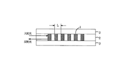
FBGは、図4に示すように光ファイバのファイバコア2の屈折率を一定の間隔周期Lで変化させたもので、光ファイバへの入射光がこの屈折率変化部1で反射する。その反射光の反射波長は、FBGの間隔周期Lとファイバコア2の屈折率で決まるため、FBGは光ファイバの歪による間隔周期の変化や温度によるファイバコア2の屈折率の変化に応じて反射波長が変化する。 As shown in FIG. 4, the FBG is obtained by changing the refractive index of the fiber core 2 of the optical fiber at a constant interval period L, and the incident light to the optical fiber is reflected by the refractive index changing unit 1. Since the reflection wavelength of the reflected light is determined by the interval period L of the FBG and the refractive index of the fiber core 2, the FBG is reflected according to the change of the interval period due to strain of the optical fiber and the change of the refractive index of the fiber core 2 due to temperature. Wavelength changes.
そのためFBGを有した光ファイバは、ファイバコア2の歪と温度に対してセンサとしての感度を持ち、圧力、歪、温度の測定をするための様々な光式センサとしての研究がなされている。 Therefore, the optical fiber having the FBG has sensitivity as a sensor with respect to the strain and temperature of the fiber core 2, and studies as various optical sensors for measuring pressure, strain, and temperature have been made.
一般的にFBGにて圧力、歪の計測をする光式センサの場合、測定対象物の圧力、歪をFBGへ印加するために測定対象物に固定する必要がある。 In general, in the case of an optical sensor that measures pressure and strain with an FBG, it is necessary to fix the pressure and strain of the measurement object to the measurement object in order to apply the FBG to the FBG.
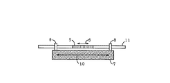
湿度を計測する光式センサの場合も同様で、図5に示すように、FBG5が設けられた光ファイバ11を湿度によって膨張、収縮する湿度検出材料7へ接着剤等を用いて固定点8、9に固定する。例えば膨張の場合、主に図中矢印10で示す方向に湿度によって湿度検出材料7が膨張し、これに応じて光ファイバ11のFBG5の部分が矢印6で示す方向に伸長することにより、湿度変化によるFBG5の屈折率周期が変化しFBG5で反射する反射光の波長が変化することで、湿度を測定することができる。
The same applies to an optical sensor that measures humidity. As shown in FIG. 5, the
なお、この出願の発明に関連する先行技術文献情報としては、次のものがある。 The prior art document information related to the invention of this application includes the following.
しかしながら、この光ファイバ11を湿度検出材料7に固定する方法によると、接着剤とFBG5が形成されている光ファイバ11との間の接着力の低下や、湿度による接着剤そのものの膨張、収縮等の影響があり、計測の信頼性及び計測精度が悪くなる傾向があるという問題がある。
However, according to the method of fixing the
また、接着作業を行う工程のコストも見込まなければならなくなるため、製造コストも高くなるという問題がある。 Moreover, since the cost of the process of performing the bonding operation must be expected, there is a problem that the manufacturing cost increases.
そこで、本発明の目的は、FBGを用いて簡単かつ安価な構成にて、容易に多点の湿度を計測するためのFBG湿度センサ及びFBG湿度センサを用いた湿度測定方法を提供することにある。 Therefore, an object of the present invention is to provide an FBG humidity sensor and a humidity measurement method using the FBG humidity sensor for easily measuring multi-point humidity with a simple and inexpensive configuration using the FBG. .
本発明は上記目的を達成するために創案されたものであり、第1の発明は、FBGを備えた光ファイバの表面に、湿度変化に応じて膨張、収縮する湿度検出材料を塗布したFBG湿度センサである。 The present invention was devised to achieve the above object, and the first invention is an FBG humidity in which a humidity detection material that expands and contracts in response to changes in humidity is applied to the surface of an optical fiber equipped with an FBG. It is a sensor.
第2の発明は、湿度によって膨張、収縮する上記湿度検出材料が、上記光ファイバとの接着力が強いポリイミドである。 In a second aspect of the invention, the humidity detecting material that expands and contracts due to humidity is polyimide having a strong adhesive force to the optical fiber.
第3の発明は、上記光ファイバの外径が40μm〜130μmであり、上記光ファイバに塗布された上記湿度検出材料の膜厚が2μm〜50μmである。 In a third aspect of the present invention, the outer diameter of the optical fiber is 40 μm to 130 μm, and the film thickness of the humidity detection material applied to the optical fiber is 2 μm to 50 μm.
第4の発明は、FBGを備えた光ファイバの表面に、湿度変化に応じて膨張、収縮する湿度検出材料を塗布し、該湿度検出材料が湿度変化に応じて膨張、収縮することにより、上記光ファイバに歪を生じさせ、この上記光ファイバの歪に応じて上記FBGの反射波長を変化させ、その反射波長の変化を計測して、湿度を検出するFBG湿度センサを用いた湿度測定方法である。 According to a fourth aspect of the present invention, the surface of the optical fiber including the FBG is coated with a humidity detection material that expands and contracts in response to a change in humidity, and the humidity detection material expands and contracts in response to a change in humidity. In a humidity measurement method using an FBG humidity sensor that detects the humidity by causing distortion in the optical fiber, changing the reflection wavelength of the FBG according to the distortion of the optical fiber, measuring the change in the reflection wavelength, is there.
第5の発明は、上記FBGの湿度による波長変化を計測して、湿度変化と波長変化の検量線を予め作成し、湿度計測時に検出した波長変化から上記検量線を基に湿度を求める方法である。 The fifth invention is a method of measuring the wavelength change due to the humidity of the FBG, preparing a calibration curve of the humidity change and the wavelength change in advance, and obtaining the humidity based on the calibration curve from the wavelength change detected during humidity measurement. is there.
本発明によれば、容易に多点の湿度を計測するためのFBG湿度センサ及びFBG湿度センサを用いた湿度測定方法を得られる。 ADVANTAGE OF THE INVENTION According to this invention, the humidity measuring method using the FBG humidity sensor and FBG humidity sensor for measuring humidity of many points easily can be obtained.
以下、本発明の好適な一実施形態を添付図面にしたがって説明する。 DESCRIPTION OF EXEMPLARY EMBODIMENTS Hereinafter, a preferred embodiment of the invention will be described with reference to the accompanying drawings.
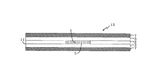
図1は、本発明の好適実施の形態を示すFBG湿度センサを示す断面図である。 FIG. 1 is a cross-sectional view showing an FBG humidity sensor showing a preferred embodiment of the present invention.
図示したように、FBG湿度センサ13は、架橋アクリル樹脂(熱硬化アクリル樹脂)、シリコーン樹脂等で形成した屈折率の高いファイバコア2と、水分を透過しないフッ素樹脂等でファイバコア2の周囲に設けられた屈折率の低いファイバクラッド3とからなる光ファイバ11のファイバクラッド3の外周部に、更に湿度によって膨張、収縮する湿度検出材料7を薄く膜状に塗布した構造になっている。
As shown in the figure, the
本実施の形態では例えばFBG湿度センサ13の寸法は、FBG湿度センサ13のファイバコア2のコア径がφ9.5μmであり、光ファイバ11の外径(すなわち、ファイバクラッド3のクラッド径)がφ125μmであり、そのファイバクラッド3の周囲に湿度によって膨張、収縮する湿度検出材料7としてポリイミドからなる膜厚10μmのコーティングがなされている。
In the present embodiment, for example, the
本発明では、FBG湿度センサ13の使用される環境、適用条件などにより、ファイバコア2のコア径をφ9μm〜20μmの範囲で、光ファイバ11の外径をφ40μm〜130μmの範囲で、光ファイバ11に塗布する湿度検出材料7の膜厚を厚さ2μm〜50μmの範囲で各々適宜設定して、FBG湿度センサ13の感度、精度が最適になるようにするとよい。
In the present invention, depending on the environment in which the
なお、このファイバクラッド3に外周に設けられる湿度検出材料7による薄い膜は、塗布、コーティングに限らず、ファイバクラッド3上に強い接着力を保持して設けられればよい。 Note that the thin film made of the humidity detecting material 7 provided on the outer periphery of the fiber clad 3 is not limited to coating and coating, and may be provided with a strong adhesive force on the fiber clad 3.
ファイバコア2には、ファイバコア2の長手方向にファイバコア2とは異なる屈折率の屈折率変化部1を一定の間隔周期で形成した回折格子であるFBG5が設けられている。このファイバコア2に設けられたFBG5のため、光ファイバ11を伝搬する光信号の内、このFBG5において特定波長の光信号を反射して、他の波長の光信号を通過させる。
The fiber core 2 is provided with an FBG 5 that is a diffraction grating in which the refractive index changing portions 1 having a refractive index different from that of the fiber core 2 are formed in the longitudinal direction of the fiber core 2 at a constant interval period. Because of the FBG 5 provided in the fiber core 2, among the optical signals propagating through the
このFBG湿度センサ13の湿度の検出方法は次の通りである。
The method of detecting the humidity of the
或る湿度雰囲気内に設置されたFBG湿度センサ13は、FBG湿度センサ13に入射した光信号の内、FBG湿度センサ13のFBG5を形成している一定の間隔周期で設けられた屈折率変化部1の間隔周期に応じた波長のみをFBG5において反射する。
The
次に、FBG湿度センサ13の設置された雰囲気内の湿度が仮に高くなったと
する。この雰囲気内の湿度が高くなったことにより、ポリイミドなどからなる湿度検出材料7は雰囲気内の湿気を吸収し、この湿気を吸収した湿度検出材料7は、その吸収した湿気による湿度変化に応じて光ファイバ11長手方向に膨張、伸長する。この湿気を吸収し伸長した湿度検出材料7は、光ファイバ11との接着力が強く光ファイバ11のファイバクラッド3の表面に密着して塗布(コーティング)されているため、湿度検出材料7の伸長に従って、光ファイバ11に歪を生じさせ光ファイバ11にも伸長の応力が生じて、湿度検出材料7の伸長と同時に光ファイバ11も光ファイバ11長手方向に伸長する。
Next, it is assumed that the humidity in the atmosphere where the
このように、FBG湿度センサ13が設置された雰囲気内の湿度が高くなることで、湿度検出材料7及び光ファイバ11が伸長するため、光ファイバ11のファイバコア2に設けられているFBG5も光ファイバ11長手方向に伸長する。
As described above, since the humidity in the atmosphere in which the
このFBG5の伸長は、FBG5に回折格子を形成している屈折率変化部1の間隔周期を伸長させることを意味し、この屈折率変化部1の間隔周期(すなわち、屈折率変化部1の屈折率分布)が、光ファイバの歪に応じて伸長することにより、FBG5で反射する光信号の波長が長波長側に変化する。 The extension of the FBG 5 means that the interval period of the refractive index changing unit 1 that forms a diffraction grating in the FBG 5 is extended, and the interval period of the refractive index changing unit 1 (that is, the refraction of the refractive index changing unit 1). The rate distribution) expands according to the strain of the optical fiber, whereby the wavelength of the optical signal reflected by the FBG 5 changes to the long wavelength side.
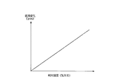
このFBG湿度センサ13を用いて、FBG湿度センサ13が設置された雰囲気内の相対湿度の変化と、相対湿度が変化したときのFBG湿度センサ13の反射する光信号の波長変化の関係を観測したところ、図2に示すような検量線が得られることが分かった。
Using this
図2にFBG湿度センサ13が設置された雰囲気の相対湿度と、この相対湿度に対応して変化する反射波の波長変化との関係を示す。図中横軸は、FBG湿度センサ13が設置された雰囲気中の相対湿度(単位:%RH)を示し、縦軸はFBG湿度センサ13の反射光の波長変化(単位:pm)を示す。
FIG. 2 shows the relationship between the relative humidity of the atmosphere in which the
図から分かるように、FBG湿度センサ13が設置された雰囲気中の相対湿度が高くなるに従って波長変化が大きくなり、相対湿度に対して波長変化がほぼ比例関係にあることが分かる。
As can be seen from the figure, the wavelength change increases as the relative humidity in the atmosphere in which the
実測値の一例として、上記のようなFBG湿度センサ13に中心波長1550nmの光を入射したときに、雰囲気内の相対湿度が50%RHから90%RHに上昇することによって、FBG湿度センサ13において反射する光の中心波長変化(波長シフト)が長波長側に約20pmであることが観測された。
As an example of the actual measurement value, when light having a central wavelength of 1550 nm is incident on the
なお、ここではFBG湿度センサ13が設置された雰囲気内の湿度が上昇するときに湿度検出材料7が膨張する場合を説明したが、湿度が低下するときに湿度検出材料7が収縮する場合も同様である。
In addition, although the case where the humidity detection material 7 expand | swells when the humidity in the atmosphere in which the
また、湿度が上昇するときに膨張し、湿度が低下するときに収縮する材質の場合について説明したが、湿度が上昇するときに収縮し、湿度が低下するときに膨張する材質の湿度検出材料7を用いてもよい。 Further, the case of a material that expands when the humidity increases and contracts when the humidity decreases has been described. However, the humidity detection material 7 is a material that contracts when the humidity increases and expands when the humidity decreases. May be used.
次に、このようにして形成されたFBG湿度センサ13を用いた湿度計測システムの一例を説明する。
Next, an example of a humidity measurement system using the
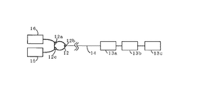
図3は、FBG湿度センサを用いた湿度計測システムを示す構成図である。 FIG. 3 is a configuration diagram showing a humidity measurement system using an FBG humidity sensor.
図示したように湿度計測システムは、広帯域の光信号を発する広帯域光源16と、広帯域光源16から入射された光信号を通過、反射させるFBG湿度センサ13a〜13cと、FBG湿度センサ13a〜13cで反射した光信号の波長を測定するための波長計測装置15と、入射した信号光、反射した信号光を一方向に伝送するための光サーキュレータ12と、計測システムのこれら各部材間を接続するための光ファイバケーブル14とを備えて構成される。
As shown in the drawing, the humidity measurement system includes a broadband light source 16 that emits a broadband optical signal, an
広帯域光源16は、光ファイバケーブル14により、光サーキュレータ12の端子12aに接続され、光サーキュレータ12の端子12bには光ファイバケーブル14を介してFBG湿度センサ13aが接続されている。FBG湿度センサ13aの他端には、光ファイバケーブル14を介してFBG湿度センサ13bが接続され、FBG湿度センサ13aの他端には光ファイバケーブル14を介してFBG湿度センサ13cが接続されている。光サーキュレータ12の端子12cには光ファイバケーブル14を介して波長計測装置15が接続されている。
The broadband light source 16 is connected to a terminal 12 a of the
広帯域光源16は、異なる波長の光信号を発することのできる広帯域の光源である。 The broadband light source 16 is a broadband light source that can emit optical signals having different wavelengths.
波長計測装置15は、FBG湿度センサ13a〜13cからの反射光の波長を測定し、その波長変化を検知して、図2に示す検量線に照合して波長変化に応じた相対湿度値を示す計測機器である。
The
光サーキュレータ12は、光サーキュレータ12の特定の端子に入射された光信号を特定の端子に出力する入出力方向性を有した光回路部品であり、端子12aに入射した光信号を端子12bに出力し、端子12bに入射した光信号を端子12cに出力し、端子12cに入射した光信号を端子12aに出力する。
The
FBG湿度センサ13a〜13cは、図1に示したFBG湿度センサ13と同様に構成された湿度センサであり、FBG湿度センサ13a〜13cの各々に設けられたFBG5は、FBG5を形成する屈折率変化部1の間隔周期を異ならせ、それぞれ特定の波長の光信号を反射するように形成するとよい。
The
次に、波長計測システムによる湿度計測方法について図1〜3により説明する。 Next, a humidity measurement method using the wavelength measurement system will be described with reference to FIGS.
広帯域光源16から発せられた光信号は、光ファイバケーブル14を介して光サーキュレータ12の端子12aに入射され、この入射された光信号は端子12bから光ファイバケーブル14を介して、FBG湿度センサ13aに入射される。
An optical signal emitted from the broadband light source 16 is incident on the terminal 12a of the
この入射された光信号の内、FBG湿度センサ13aに設けられたFBG5に対応した特定の波長の光信号がFBG湿度センサ13aで反射され、光ファイバケーブル14、光サーキュレータ12の端子12b、光サーキュレータ12の端子12c、光ファイバケーブル14を順に介して、波長計測装置15に入射される。
Among the incident optical signals, an optical signal having a specific wavelength corresponding to the FBG 5 provided in the
波長計測装置15に入射された光信号(反射光)は、波長変化が計測され図2に示す検量線を基にこの光信号の波長変化に応じたFBG湿度センサ13aの設置された雰囲気中の相対湿度が得られる。
The optical signal (reflected light) incident on the
FBG湿度センサ13aを通過した他の波長の光信号は、FBG湿度センサ13bに入射され、この入射された光信号の内、FBG湿度センサ13bに設けられたFBG5に対応した特定の波長の光信号がFBG湿度センサ13bで反射され、光ファイバケーブル14、FBG湿度センサ13a、光ファイバケーブル14、光サーキュレータ12の端子12b、光サーキュレータ12の端子12c、光ファイバケーブル14を順に介して、波長計測装置15に入射され、波長計測装置15に入射された光信号(反射光)すなわちFBG湿度センサ13bから反射した光信号の波長変化が計測され、図2に示す検量線と照合してこの光信号の波長変化に応じたFBG湿度センサ13bの設置された雰囲気中の相対湿度が波長計測装置15により得られる。
An optical signal having another wavelength that has passed through the
FBG湿度センサ13a、13bを通過した他の波長の光信号は、FBG湿度センサ13cに入射され、FBG湿度センサ13cにて上記と同様の光の反射、透過が生じ、FBG湿度センサ13cからの反射光によりFBG湿度センサ13cの設置された雰囲気中の相対湿度が得られる。
Optical signals of other wavelengths that have passed through the
なお、本実施の形態では、この湿度計測システムにはFBG湿度センサ13(13a〜13c)を三個接続した例を示したが、測定点の箇所数など湿度計測システムのアプリケーションに応じて、FBG湿度センサ13の個数を増減させるとよい。
In this embodiment, an example is shown in which three FBG humidity sensors 13 (13a to 13c) are connected to the humidity measurement system. However, depending on the application of the humidity measurement system, such as the number of measurement points, the FBG The number of
一般的に、FBG湿度センサ13を多数用いて、多点の計測を行う場合、その測定可能な測定点の数(即ち、FBG湿度センサ13の数)は、広帯域光源16の波長帯域と、波長計測装置15の計測可能な波長帯域と、各FBG湿度センサ13の波長変化量によって定まるが、湿度により変化するFBG5での反射波長の中心波長変化量を必要とする湿度計測精度に調整することによって、可能な限り多くのFBG湿度センサ13を設けて、多点の湿度を計測する湿度計測システムを構築することが可能である。
In general, when multipoint measurement is performed using a large number of
また図1、図3において、湿度に応じて膨張、収縮する湿度検出材料7の塗布膜厚(コーティング膜厚)を調整したり、ポリイミド樹脂以外の様々な膨張、収縮率を有する湿度検出材料をFBG湿度センサ13a〜13cに用いることにより、一定の湿度変化によるFBG5の反射する中心波長の変化量を任意に定めたり、図2の検量線の傾きを任意に定めることが可能である。
Further, in FIGS. 1 and 3, humidity detection materials having various expansion and contraction rates other than polyimide resin can be adjusted by adjusting the coating film thickness (coating film thickness) of the humidity detection material 7 that expands and contracts according to humidity. By using it for the
以上説明したようにFBG湿度センサ13は、ファイバクラッド3の周囲に、湿度によって膨張、収縮しかつ接着力の強い湿度検出材料7を塗布(コーティング)した構造になっていることにより、従来技術(図5参照)のように固定点8、9における光ファイバ11の固定を必要とせず、固定のために接着材等も使用しないため、計測の信頼性及び計測精度を確保することができる優れた光式センサとなっている。
As described above, the
また、FBG湿度センサ13は、ファイバクラッド3の周囲に湿度によって膨張、収縮する湿度検出材料7よりコーティングされた簡単な構造になっており、かつ従来のような接着作業も不要となり製造コストも抑えられた安価な光式センサとなっている。
In addition, the
またこのようなFBG湿度センサ13は、センサ自体に電源を必要とせず、異なる反射波長を有したFBG湿度センサ13(FBG湿度センサ13a〜13c)を多点に容易に敷設することができる。このため、図3に示すような湿度計測システムに用いて、各FBG湿度センサ13からの反射光の波長を常時1つの波長計測装置15にて計測して、得られた中心波長の波長変化を図2に示した検量線に照合することで、容易に湿度を計測することが可能になった。
Further, such an
従来技術においても述べたが、FBG5は外部から印加される圧力等の歪だけによってだけでなく、そのFBG5周辺の温度変化によってもFBG5の反射中心波長は変化する。 As described in the prior art, the reflection center wavelength of the FBG 5 changes not only due to a strain such as pressure applied from the outside but also due to a temperature change around the FBG 5.
従って、FBG湿度センサ13において、湿度と温度による波長変化分から温度による波長変化分を取り除くことにより、更に高精度な湿度計測が可能である。
Therefore, the
この場合、湿度によって膨張、収縮しない材料を光ファイバ11の表面にコーティングした温度計測用のFBG温度センサまたは、湿度によって膨張、収縮するが光ファイバとの接着力が弱くその膨張、収縮による変化がFBGに応力を生じさせない材料をコーティングしたFBG温度センサをFBG湿度センサ13近傍に配置することにより、FBG湿度センサ13の温度による中心波長変化分を補正することが可能である。
In this case, an FBG temperature sensor for temperature measurement in which the surface of the
このように本発明によれば、FBGを用いて簡単かつ安価な構成にて、容易に多点の湿度を計測するためのFBG湿度センサ及びFBG湿度センサを用いた湿度測定方法を得られる。 As described above, according to the present invention, it is possible to obtain an FBG humidity sensor and a humidity measurement method using the FBG humidity sensor for easily measuring the humidity at multiple points with a simple and inexpensive configuration using the FBG.
1 屈折率変化部
2 ファイバコア
3 ファイバクラッド
5 FBG
6 矢印
7 湿度検出材料(ポリイミド)
10 矢印
11 光ファイバ
12 光サーキュレータ
12a〜12c 端子
13 FBG湿度センサ
13a〜13c FBG湿度センサ
14 光ファイバケーブル
15 波長計測装置
16 広帯域光源
L 間隔周期
DESCRIPTION OF SYMBOLS 1 Refractive index change part 2 Fiber core 3 Fiber clad 5 FBG
6 Arrow 7 Humidity detection material (Polyimide)
DESCRIPTION OF
Claims (5)
5. The FBG humidity sensor according to claim 4, wherein a wavelength change due to humidity of the FBG is measured, a calibration curve for the humidity change and the wavelength change is created in advance, and the humidity is obtained based on the calibration curve from the wavelength change detected during humidity measurement. Humidity measurement method using
Priority Applications (1)
| Application Number | Priority Date | Filing Date | Title |
|---|---|---|---|
| JP2004170074A JP2005351663A (en) | 2004-06-08 | 2004-06-08 | FBG humidity sensor and humidity measurement method using FBG humidity sensor |
Applications Claiming Priority (1)
| Application Number | Priority Date | Filing Date | Title |
|---|---|---|---|
| JP2004170074A JP2005351663A (en) | 2004-06-08 | 2004-06-08 | FBG humidity sensor and humidity measurement method using FBG humidity sensor |
Publications (1)
| Publication Number | Publication Date |
|---|---|
| JP2005351663A true JP2005351663A (en) | 2005-12-22 |
Family
ID=35586281
Family Applications (1)
| Application Number | Title | Priority Date | Filing Date |
|---|---|---|---|
| JP2004170074A Pending JP2005351663A (en) | 2004-06-08 | 2004-06-08 | FBG humidity sensor and humidity measurement method using FBG humidity sensor |
Country Status (1)
| Country | Link |
|---|---|
| JP (1) | JP2005351663A (en) |
Cited By (11)
| Publication number | Priority date | Publication date | Assignee | Title |
|---|---|---|---|---|
| CN102095687A (en) * | 2011-01-18 | 2011-06-15 | 汉鼎信息科技股份有限公司 | Fiber grating humidity sensor using hydrogel as sensing element and manufacturing method thereof |
| WO2011111178A1 (en) * | 2010-03-10 | 2011-09-15 | 富士通株式会社 | Environment measurement system and environment measurement method |
| CN102768183A (en) * | 2012-07-16 | 2012-11-07 | 华北电力大学 | System and method for online monitoring filth of fiber bragg grating transmission line |
| JP2014035312A (en) * | 2012-08-10 | 2014-02-24 | Japan Atomic Energy Agency | Moisture sensor using optical fiber |
| CN107064011A (en) * | 2017-02-09 | 2017-08-18 | 北京航天控制仪器研究所 | A kind of fiber bragg grating temperature sensor |
| CN108254317A (en) * | 2018-01-30 | 2018-07-06 | 濮阳光电产业技术研究院 | A kind of fiber bragg grating temperature sensor in non-grid region coating polyimide |
| CN109406398A (en) * | 2018-12-17 | 2019-03-01 | 南京大学 | A kind of fall-ball type soil moisture content rapid determination device and method based on fiber grating |
| CN110687076A (en) * | 2019-10-28 | 2020-01-14 | 中国科学院西安光学精密机械研究所 | Humidity sensor based on polymer optical fiber mode interferometer |
| CN111220208A (en) * | 2019-12-06 | 2020-06-02 | 山东省科学院激光研究所 | A Novel Optical Fiber Temperature and Humidity Sensor |
| CN114062271A (en) * | 2021-11-12 | 2022-02-18 | 中国电力科学研究院有限公司 | Fiber grating humidity sensor with excellent linearity, system and manufacturing method |
| KR20240111942A (en) * | 2023-01-11 | 2024-07-18 | 호남대학교 산학협력단 | humidity sensor having temperature compensation function |
-
2004
- 2004-06-08 JP JP2004170074A patent/JP2005351663A/en active Pending
Cited By (16)
| Publication number | Priority date | Publication date | Assignee | Title |
|---|---|---|---|---|
| WO2011111178A1 (en) * | 2010-03-10 | 2011-09-15 | 富士通株式会社 | Environment measurement system and environment measurement method |
| JP5445668B2 (en) * | 2010-03-10 | 2014-03-19 | 富士通株式会社 | Environmental measurement system and environmental measurement method |
| US8918286B2 (en) | 2010-03-10 | 2014-12-23 | Fujitsu Limited | Environmental measurement system and environmental measurement method |
| CN102095687A (en) * | 2011-01-18 | 2011-06-15 | 汉鼎信息科技股份有限公司 | Fiber grating humidity sensor using hydrogel as sensing element and manufacturing method thereof |
| CN102768183A (en) * | 2012-07-16 | 2012-11-07 | 华北电力大学 | System and method for online monitoring filth of fiber bragg grating transmission line |
| JP2014035312A (en) * | 2012-08-10 | 2014-02-24 | Japan Atomic Energy Agency | Moisture sensor using optical fiber |
| CN107064011B (en) * | 2017-02-09 | 2020-06-09 | 北京航天控制仪器研究所 | Fiber grating humidity sensor |
| CN107064011A (en) * | 2017-02-09 | 2017-08-18 | 北京航天控制仪器研究所 | A kind of fiber bragg grating temperature sensor |
| CN108254317A (en) * | 2018-01-30 | 2018-07-06 | 濮阳光电产业技术研究院 | A kind of fiber bragg grating temperature sensor in non-grid region coating polyimide |
| CN109406398A (en) * | 2018-12-17 | 2019-03-01 | 南京大学 | A kind of fall-ball type soil moisture content rapid determination device and method based on fiber grating |
| CN109406398B (en) * | 2018-12-17 | 2024-03-19 | 南京大学 | A device and method for rapid determination of soil moisture content using a falling ball type based on fiber grating |
| CN110687076A (en) * | 2019-10-28 | 2020-01-14 | 中国科学院西安光学精密机械研究所 | Humidity sensor based on polymer optical fiber mode interferometer |
| CN111220208A (en) * | 2019-12-06 | 2020-06-02 | 山东省科学院激光研究所 | A Novel Optical Fiber Temperature and Humidity Sensor |
| CN114062271A (en) * | 2021-11-12 | 2022-02-18 | 中国电力科学研究院有限公司 | Fiber grating humidity sensor with excellent linearity, system and manufacturing method |
| KR20240111942A (en) * | 2023-01-11 | 2024-07-18 | 호남대학교 산학협력단 | humidity sensor having temperature compensation function |
| KR102814663B1 (en) * | 2023-01-11 | 2025-05-28 | 호남대학교 산학협력단 | humidity sensor having temperature compensation function |
Similar Documents
| Publication | Publication Date | Title |
|---|---|---|
| US8727613B2 (en) | Method and system for measuring a parameter in a high temperature environment using an optical sensor | |
| JP5150445B2 (en) | Optical fiber sensor device, temperature and strain measurement method, and optical fiber sensor | |
| JP5030081B2 (en) | AE / ultrasound detection system, and material monitoring apparatus and nondestructive inspection apparatus provided with the same | |
| JP2002529728A (en) | Strain sensor with optical fiber Bragg grating | |
| JP2009063390A (en) | Optical fiber humidity sensor and humidity detection system using it | |
| WO1979000377A1 (en) | Optical sensing apparatus and method | |
| Hongo et al. | Applications of fiber Bragg grating sensors and high‐speed interrogation techniques | |
| WO2008047859A1 (en) | Optical fiber thermometer and temperature compensation optical fiber sensor | |
| JP5012032B2 (en) | Temperature measuring method and optical fiber sensor | |
| JP2008545124A (en) | Optical strain gauge | |
| JP2006250647A (en) | Wire cable, and tension measurement system and method | |
| JP2005351663A (en) | FBG humidity sensor and humidity measurement method using FBG humidity sensor | |
| CN103697921B (en) | A kind of optical fiber sensor head and based on the optical fiber sensing system of the monitor strain of this sensing head, stress and pressure and method | |
| JP5073215B2 (en) | Optical fiber cable, optical fiber physical quantity fluctuation detection sensor using the same, and physical quantity fluctuation detection method | |
| JP3925202B2 (en) | High speed wavelength detector | |
| JP5054931B2 (en) | Optical sensor | |
| CN114088003B (en) | A fiber grating sensor | |
| JP2003270041A (en) | High-speed wavelength detector | |
| JPH11101617A (en) | Structure strain monitoring method and its monitoring device | |
| JP4862594B2 (en) | Optical fiber sensor | |
| WO2009144962A1 (en) | Measuring system | |
| JP7006964B2 (en) | Optical fiber type measuring device and optical fiber type measuring method | |
| JP5178093B2 (en) | Optical sensor | |
| CN115003988A (en) | System for measuring multiple physical parameters at a measurement point using multimode optical fiber | |
| KR102633654B1 (en) | Fiber-optic Confocal Deformation Sensor and Strain Sensor Device Comprising The Same |