JP2005351525A - Waste treatment system - Google Patents
Waste treatment system Download PDFInfo
- Publication number
- JP2005351525A JP2005351525A JP2004171493A JP2004171493A JP2005351525A JP 2005351525 A JP2005351525 A JP 2005351525A JP 2004171493 A JP2004171493 A JP 2004171493A JP 2004171493 A JP2004171493 A JP 2004171493A JP 2005351525 A JP2005351525 A JP 2005351525A
- Authority
- JP
- Japan
- Prior art keywords
- fluidized bed
- bed gasification
- melting
- bag filter
- waste
- Prior art date
- Legal status (The legal status is an assumption and is not a legal conclusion. Google has not performed a legal analysis and makes no representation as to the accuracy of the status listed.)
- Pending
Links
Images


Abstract
Description
本発明は、廃棄物処理システムに係り、特に低カロリー廃棄物と高カロリー廃棄物とが混在した廃棄物を処理する廃棄物処理システムに関するものである。 The present invention relates to a waste treatment system, and more particularly, to a waste treatment system for treating waste in which low-calorie waste and high-calorie waste are mixed.
近年、廃棄物を処理する廃棄物処理システムとしてガス化溶融炉が用いられているが、このようなガス化溶融炉では、灰を溶融するために炉内の温度を高くする必要がある。したがって、低カロリー廃棄物と高カロリー廃棄物とが混在した廃棄物の全量をガス化溶融炉で処理しようとする場合には、必要となる補助燃料等の量が増え、運転コストが高くなってしまうことがある。また、焼却炉と溶融炉とを組み合わせた廃棄物処理システムも開発されているが、これらの廃棄物処理システムは、灰の溶融炉としてシャフト炉を使用したものであったり、廃棄物焼却炉と廃プラスチックガス化・灰溶融装置との組み合わせによるものであったりして、廃棄物を焼却炉とガス化溶融炉の双方で処理しつつ、焼却炉で発生する灰を溶融処理することができるものではなかった。(例えば、特許文献1から4参照)。
本発明は、このような従来技術の問題点に鑑みてなされたもので、特別な装置や運転管理を必要とせず低コストで操業することができる廃棄物処理システムを提供することを目的とする。 The present invention has been made in view of such problems of the prior art, and an object of the present invention is to provide a waste treatment system that can be operated at low cost without requiring special equipment or operation management. .
本発明の一態様によれば、廃棄物を焼却する焼却炉を有する燃焼装置と、廃棄物をガス化する流動床ガス化炉と、該流動床ガス化炉で発生した生成ガスを高温で燃焼し、灰分を溶融する溶融炉とを有する流動床ガス化溶融装置とを備えた廃棄物処理システムが提供される。この廃棄物処理システムは、上記燃焼装置で生成された灰を上記流動床ガス化溶融装置の流動床ガス化炉に供給する不燃物供給路を備えている。上記焼却炉は、ストーカ焼却炉または流動床焼却炉であることが好ましい。 According to one aspect of the present invention, a combustion apparatus having an incinerator that incinerates waste, a fluidized bed gasification furnace that gasifies waste, and a product gas generated in the fluidized bed gasification furnace is combusted at a high temperature. And a waste treatment system including a fluidized bed gasification melting apparatus having a melting furnace for melting ash. This waste treatment system includes an incombustible material supply path for supplying the ash produced by the combustion device to the fluidized bed gasification furnace of the fluidized bed gasification melting device. The incinerator is preferably a stoker incinerator or a fluidized bed incinerator.
廃棄物は分別収集等により低カロリー廃棄物と高カロリー廃棄物とに分けることができるので、受け入れピットで区分けして貯留できる。本発明によれば、燃料があまり必要ではない燃焼装置に低カロリー廃棄物を供給し、流動床ガス化溶融装置になるべく高カロリーの廃棄物を供給することにより、システム全体として必要となる補助燃料等の量を削減することができ、システムの運転コストを削減することができる。また、燃焼装置で生成された灰は流動床ガス化溶融装置の流動床ガス化炉に供給されるので、別途の装置を設けることなく、ガス化溶融装置を運転することにより焼却炉で生成された灰を溶融することができる。また、例えば焼却炉としてストーカ焼却炉を用いる場合、ストーカ焼却炉で生成され炉下から排出される焼却灰には金属類や瓦礫類が灰分と混在しているが、この焼却灰を流動床ガス化炉に供給することにより、流動床のクリーニング効果により灰分を分離し金属類や瓦礫類を有効利用しやすい清浄化された状態で回収することができる。 Since waste can be separated into low-calorie waste and high-calorie waste by separate collection, etc., it can be stored separately by receiving pits. According to the present invention, low calorie waste is supplied to a combustion device that does not require much fuel, and high calorie waste is supplied to the fluidized bed gasification and melting device, so that the auxiliary fuel required for the entire system is obtained. Etc., and the operating cost of the system can be reduced. In addition, since the ash produced in the combustion device is supplied to the fluidized bed gasification furnace of the fluidized bed gasification and melting device, it is generated in the incinerator by operating the gasification and melting device without providing a separate device. Ash can be melted. For example, when a stoker incinerator is used as an incinerator, the incinerated ash generated in the stoker incinerator and discharged from the bottom of the incinerator contains metal and debris mixed with ash. By supplying to the chemical furnace, the ash can be separated by the cleaning effect of the fluidized bed and recovered in a purified state in which metals and rubble can be effectively used.
ここで、燃焼装置で生成された灰を貯留槽に貯留し、該貯留槽から流動床ガス化溶融装置の流動床ガス化炉に供給することが好ましい。このように、焼却装置で生成された灰を流動床ガス化溶融装置の流動床ガス化炉に貯留槽を介して供給することにより、焼却装置と流動床ガス化溶融装置の運転を独立して行うことができる。 Here, it is preferable to store the ash produced | generated with the combustion apparatus in the storage tank, and to supply to the fluidized bed gasification furnace of a fluidized bed gasification melting apparatus from this storage tank. Thus, by supplying the ash produced by the incinerator to the fluidized bed gasification furnace of the fluidized bed gasification and melting apparatus via the storage tank, the operation of the incineration apparatus and the fluidized bed gasification and melting apparatus can be performed independently. It can be carried out.
また、流動床ガス化溶融装置は、流動床ガス化炉の炉底から流動媒体とともに不燃物を抜き出し、流動媒体と不燃物を分別し、さらに不燃物中の金属類を分離した後、不燃物を粉砕して該流動床ガス化炉に戻す不燃物処理装置を有することが好ましい。この場合には、システム全体として必要となる補助燃料等の量を削減することができ、システムの運転コストを削減することができる。また、流動床ガス化溶融装置の流動床ガス化炉が、不燃物を粉砕して該流動床ガス化炉に戻す不燃物処理装置を有しているため、流動床ガス化炉に供給される廃棄物に含まれる土砂や瓦礫、石ころ、ガラス等の不燃物は粉砕されて流動床ガス化炉に戻され、流動床ガス化炉から溶融炉に送られスラグとして回収される。燃焼装置から排出された灰は流動床ガス化溶融装置の流動床ガス化炉に供給されるので、別途の装置を設けることなく、流動床ガス化溶融装置を運転することにより、燃焼装置から排出される灰分は土砂や瓦礫、石ころ、ガラス等の不燃物を含めて溶融処理することができる。 In addition, the fluidized bed gasification and melting apparatus extracts the incombustible material together with the fluidized medium from the bottom of the fluidized bed gasification furnace, separates the fluidized medium from the incombustible material, further separates the metals in the incombustible material, It is preferable to have an incombustible material processing apparatus that pulverizes and returns to the fluidized bed gasification furnace. In this case, the amount of auxiliary fuel or the like required for the entire system can be reduced, and the operating cost of the system can be reduced. Further, since the fluidized bed gasification furnace of the fluidized bed gasification and melting apparatus has an incombustible material treatment device that pulverizes the incombustible material and returns it to the fluidized bed gasification furnace, it is supplied to the fluidized bed gasification furnace. Incombustible materials such as earth and sand, rubble, stones and glass contained in the waste are pulverized and returned to the fluidized bed gasification furnace, sent from the fluidized bed gasification furnace to the melting furnace, and recovered as slag. Since the ash discharged from the combustion device is supplied to the fluidized bed gasification furnace of the fluidized bed gasification and melting device, it is discharged from the combustion device by operating the fluidized bed gasification and melting device without providing a separate device. The ash content can be melted including incombustibles such as earth and sand, rubble, stones and glass.
また、燃焼装置の焼却炉が流動床焼却炉である場合には、焼却炉から流動媒体とともに抜き出される焼却灰は金属類、土砂、瓦礫、ガラスおよび陶磁器片であるため、そのままあるいは金属類を選別した後、流動床ガス化炉の不燃物抜き出し部に合流させてもよい。 In addition, when the incinerator of the combustor is a fluidized bed incinerator, the incineration ash withdrawn together with the fluid medium from the incinerator is metals, earth and sand, rubble, glass and ceramic pieces. After sorting, you may make it merge with the incombustible material extraction part of a fluidized bed gasifier.
ここで、上記燃焼装置は、第1のバグフィルタと該第1のバグフィルタの下流に設けられた第2のバグフィルタとを備えることができ、同様に上記ガス化溶融装置も、第1のバグフィルタと該第1のバグフィルタの下流に設けられた第2のバグフィルタとを備えることができる。また、上記燃焼装置および上記流動床ガス化溶融装置にそれぞれ第1のバグフィルタを設け、上記燃焼装置および上記流動床ガス化溶融装置に共通して使用される第2のバグフィルタを設けてもよい。また、上記燃焼装置の第1のバグフィルタにより除去された飛灰を上記流動床ガス化溶融装置の溶融炉に供給する不燃物供給路を設けてもよい。さらに、上記燃焼装置の第1のバグフィルタと不燃物供給路との間に、第1のバグフィルタにより除去された飛灰を貯留する貯留槽を設けてもよい。 Here, the combustion apparatus can include a first bag filter and a second bag filter provided downstream of the first bag filter. Similarly, the gasification and melting apparatus also includes the first bag filter. A bug filter and a second bug filter provided downstream of the first bug filter can be provided. Alternatively, a first bag filter may be provided in each of the combustion device and the fluidized bed gasification and melting device, and a second bag filter that is commonly used in the combustion device and the fluidized bed gasification and melting device may be provided. Good. Moreover, you may provide the nonflammable material supply path which supplies the fly ash removed by the 1st bag filter of the said combustion apparatus to the melting furnace of the said fluidized bed gasification melting apparatus. Furthermore, you may provide the storage tank which stores the fly ash removed by the 1st bag filter between the 1st bag filter of the said combustion apparatus, and an incombustible material supply path.
本発明の廃棄物処理システムによれば、特別な装置を必要とせず、最少の補助燃料により灰分を溶融処理することができ、運転費を大幅に削減することができる。また、流動床ガス化溶融装置を安定に稼動させ、補助燃料必要量を削減するために、廃棄物を破砕等の前処理をして供給の定量性を高めることが行われるが、本発明では、燃焼装置と流動床ガス化溶融装置とを組み合わせたシステムとすることにより、上記破砕等の前処理は流動床ガス化溶融装置にのみ設ければよいので前処理を簡素化することができる。破砕に不適な異物を含有する廃棄物の処理においては、上記前処理で安定運転が阻害されることがしばしばあるため、前処理の簡素化により廃棄物処理システムのより安定した稼動が可能となる。 According to the waste treatment system of the present invention, no special device is required, and the ash can be melted with a minimum amount of auxiliary fuel, so that the operating cost can be greatly reduced. Further, in order to operate the fluidized bed gasification and melting apparatus stably and reduce the amount of auxiliary fuel, pretreatment such as crushing waste is performed to improve the quantitativeness of the supply. By using a system that combines a combustion apparatus and a fluidized bed gasification and melting apparatus, the pretreatment such as crushing need only be provided in the fluidized bed gasification and melting apparatus, so that the pretreatment can be simplified. In the treatment of waste containing foreign matters that are not suitable for crushing, stable operation is often hindered by the above-mentioned pretreatment. Therefore, the waste treatment system can be operated more stably by simplifying the pretreatment. .
以下、本発明に係る廃棄物処理システムの実施形態について図1から図3を参照して詳細に説明する。なお、図1から図3において、同一または相当する構成要素には、同一の符号を付して重複した説明を省略する。 Hereinafter, an embodiment of a waste treatment system according to the present invention will be described in detail with reference to FIGS. 1 to 3. 1 to 3, the same or corresponding components are denoted by the same reference numerals, and redundant description is omitted.
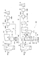
図1は、本発明の第1の実施形態における廃棄物処理システムを示すフローシートである。図1に示すように、廃棄物処理システムは、ストーカ焼却炉10を有する燃焼装置1と、流動床ガス化炉20と旋回式溶融炉21とを有する流動床ガス化溶融装置2とを備えている。
FIG. 1 is a flow sheet showing a waste treatment system according to a first embodiment of the present invention. As shown in FIG. 1, the waste treatment system includes a combustion apparatus 1 having a
燃焼装置1は、廃棄物が投入されるピット11と、廃棄物をピット11からホッパ12に移すためのクレーン13とを備えている。このピット11には、例えば4200〜8400kJ/kg(1000〜2000kcal/kg)の低カロリー廃棄物が投入される。ピット11に投入された低カロリー廃棄物は、クレーン13によりホッパ12に投入される。
The combustion apparatus 1 includes a
燃焼装置1のストーカ焼却炉10は、乾燥ストーカ10aと、燃焼ストーカ10bと、後燃焼ストーカ10cとを備えており、ホッパ12からプッシャ(図示せず)を介して焼却炉10に供給された廃棄物は、乾燥ストーカ10a、燃焼ストーカ10b、後燃焼ストーカ10cによって焼却炉10内をゆっくりと反転しながら移送され、乾燥および燃焼され完全に焼却されて灰になる。このストーカ焼却炉10での燃焼は、例えば900℃〜1000℃で行われ、廃棄物のカロリーが低くても燃焼させることができる。焼却後の焼却灰は排出路10dを通じて排出される。
The
また、燃焼装置1は、図1に示すように、焼却炉10で発生する排ガスを冷却すると同時に熱を回収して蒸気を生成するボイラ14と、ボイラ14からの排ガスをさらに冷却すると同時に熱を回収するエコノマイザ15と、エコノマイザ15からの排ガスを急速に冷却する減温塔16と、減温塔16からの排ガスに活性炭を添加して排ガス中のダイオキシン類を除去する第1段のバグフィルタ17と、第1段のバグフィルタ17からの排ガスに消石灰を添加して排ガス中のHClガスを除去する第2段のバグフィルタ18と、第2段のバグフィルタ18からの排ガスを排出する煙突19とを備えている。
In addition, as shown in FIG. 1, the combustion apparatus 1 cools the exhaust gas generated in the
焼却炉10で完全燃焼した排ガスは、ボイラ14およびエコノマイザ15で熱回収され、さらに減温塔16で冷却される。減温塔16を出た排ガス中のダイオキシン類等の有害成分は活性炭に吸着され第1段のバグフィルタ17により取り除かれる。第1段のバグフィルタ17を出た排ガス中のHClガスは消石灰で中和され、第2段のバグフィルタ18により中和灰が取り除かれる。このようにしてクリーンになった排ガスは煙突19から大気に放出される。
The exhaust gas completely burned in the
流動床ガス化溶融装置2は、廃棄物が投入されるピット22と、廃棄物をピット22からホッパ23に移すためのクレーン24とを備えている。このピット22には、例えば8400kJ/kg(2000kcal/kg)以上の高カロリー廃棄物が投入される。ピット22に投入された高カロリー廃棄物は、クレーン24によりホッパ23に投入される。
The fluidized bed gasification and
流動床ガス化溶融装置2は、投入された廃棄物をガス化する流動床ガス化炉20と、流動床ガス化炉20で発生した生成ガスを高温燃焼する旋回溶融炉21とを備えている。流動床ガス化炉20の内部には、炉床から吹き込まれる流動化ガスにより硅砂等の流動媒体が流動する流動層20aが形成されている。
The fluidized bed gasification and
ホッパ23に投入された廃棄物は、給塵装置(図示せず)により破砕された状態で流動床ガス化炉20に導入される。流動床ガス化炉20に投入された廃棄物は、完全燃焼に必要な理論酸素量よりも低い酸素量で500〜600℃に加熱されて熱分解ガス化される。なお、この流動床ガス化炉20によれば、流動層20aの温度が低く、しかも還元雰囲気であるため、不燃物中の鉄、銅、アルミニウムなどの金属を未酸化の状態で回収することができる。
The waste thrown into the
流動床ガス化炉20で生成された、チャーやタールを含む熱分解ガスは後段の旋回溶融炉21に送られ、1200〜1500℃の高温で燃焼される。このとき熱分解ガスとともに旋回溶融炉21に供給される灰分は旋回流により溶融炉21の壁で捕集され、スラグとなり溶融炉21の底部から排出される。この旋回溶融炉21では1200℃以上で熱分解ガスを燃焼するため、ダイオキシン類の完全分解が可能である。
The pyrolysis gas containing char and tar generated in the fluidized
また、ガス化溶融装置2は、図1に示すように、溶融炉21で発生する排ガスを冷却すると同時に熱を回収して蒸気を生成するボイラ25と、ボイラ25からの排ガスを急速に冷却する減温塔26と、減温塔26からの排ガスを除塵する第1段のバグフィルタ27と、第1段のバグフィルタ27からの排ガスに消石灰を添加して排ガス中のHClガスを除去する第2段のバグフィルタ28と、第2段のバグフィルタ28からの排ガスを排出する煙突29とを備えている。なお、第1段のバグフィルタ27の後段に触媒反応塔を設けてもよい。
Further, as shown in FIG. 1, the gasification and
溶融炉21から出た排ガスは、ボイラ25で熱回収され、さらに減温塔26で冷却される。減温塔26を出た排ガスは第1段のバグフィルタ27により除塵される。この第1段のバグフィルタ27により除去された飛灰は重金属類の溶出防止のためフェライト処理などを施して排出される。その後、排ガス中のHClガスが消石灰で中和され、第2段のバグフィルタ28により中和灰が取り除かれる。このようにしてクリーンになった排ガスは煙突29から大気に放出される。
The exhaust gas emitted from the melting
ここで、燃焼装置1のストーカ焼却炉10の排出路10dから排出された焼却灰は、貯留槽50に貯留され、灰供給路30を通じてガス化溶融装置2の流動床ガス化炉20に供給される。一般に、ストーカ焼却炉から排出される焼却灰は金属類、瓦礫類および灰分が混在しているが、この灰を流動床ガス化炉20に供給することにより、流動床20aのクリーニング効果により灰分を分離し金属類や瓦礫類を有効利用しやすい清浄化された状態で回収することができる。また、灰分は流動床20aで微粒子となり溶融炉21に送られ溶融されるので、別途の装置を必要とすることなく、流動床ガス化溶融装置2により灰分を溶融処理することができる。
Here, the incineration ash discharged from the
流動床ガス化炉20の流動床20aで微粒子とならなかった灰分は、不燃物として流動媒体とともにガス化炉20の炉下から排出される。また、燃焼装置1の焼却炉10で生成された灰は、流動床ガス化溶融装置2の前段の流動床ガス化炉20に貯留槽50を介して供給されるので、燃焼装置1と流動床ガス化溶融装置2の運転を独立して行うことができる。
The ash that has not become fine particles in the
また、燃焼装置1の第1段のバグフィルタ17により除去された飛灰はダイオキシン類を吸着した活性炭を含んでいるが、この飛灰は貯留槽52を介して飛灰供給路32からガス化溶融装置2の溶融炉21に送られる。この飛灰は溶融炉21で溶融されて、ダイオキシン類等は分解し無害化され、活性炭は燃焼し高温を維持するために寄与するとともに、灰分は減容化されたスラグになる。このように、ガス化溶融装置2の溶融炉21に送られる飛灰は薬液処理を行う前のものであるので、HClなどが再発生することがない。なお、図1に示すように、ガス化溶融装置2の第1段のバグフィルタ27により除去された飛灰の一部を飛灰供給路34を介してガス化炉20に戻して灰分のスラグへの転換率を向上させることができる。
The fly ash removed by the first
流動床ガス化炉20の炉底の不燃物は、不燃物排出装置40によって炉底から抜き出される。不燃物中の砂は、砂循環エレベータ(図示せず)により流動床ガス化炉20に戻され(図1のA参照)、砂以外の不燃物は磁選機および非鉄金属選別機42に導入される。不燃物から鉄および非鉄金属が選別された残りの不燃物は不燃物処理装置44に送られる。この不燃物処理装置44は粉砕機などを有しており、不燃物を粉砕して流動床ガス化炉20に戻し(図1のB参照)、さらにガス化炉20から旋回溶融炉21に供給することにより、不燃物をスラグとして回収する。
The incombustibles at the bottom of the fluidized
上述の第1の実施形態においては、燃焼装置1と流動床ガス化溶融装置2の双方に、第2のバグフィルタ18,28および煙突19,29が設けられていたが、これらを共有することもできる。図2は、燃焼装置101と流動床ガス化溶融装置102とで第2のバグフィルタ118および煙突119を共有した本発明の第2の実施形態に係る廃棄物処理システムを示す。このような共有化により設備のコストを低減することができる。また、燃焼装置1と流動床ガス化溶融装置2とでピットおよびクレーンを共有し、ピット内で高カロリー廃棄物と低カロリー廃棄物を区分して貯留することもできる。
In the first embodiment described above, the second bag filters 18 and 28 and the
図3は、本発明の第3の実施形態における廃棄物処理システムを示すフローシートである。上述した第1および第2の実施形態では、燃焼装置においてストーカ焼却炉を用いた例として説明したが、本実施形態では、燃焼装置201において旋回流型流動床焼却炉210を用いている。
FIG. 3 is a flow sheet showing a waste disposal system in the third embodiment of the present invention. In the first and second embodiments described above, the example in which the stoker incinerator is used in the combustion apparatus has been described. However, in the present embodiment, the swirl type
燃焼装置201の旋回流型流動床焼却炉210の内部には、炉床から吹き込まれる流動化ガスにより硅砂等の流動媒体が流動する流動層210aが形成されている。ホッパ12に投入された廃棄物は、給塵装置(図示せず)により粉砕された状態で流動床焼却炉210に導入される。流動床焼却炉210に投入された廃棄物は、流動層210a内の高温の流動媒体と激しく混合されて短時間で乾留ガス化され、燃焼される。不燃物は炉底に沈み、不燃物排出装置(図示せず)によって流動媒体とともに炉底から抜き出される。
Inside the swirl type
流動床焼却炉210から出た排ガスは、ボイラ214で熱回収され、さらに減温塔26で冷却される。減温塔26を出た排ガスは第1段のバグフィルタ27により除塵された後、排ガス中のHClガスが消石灰で中和され、第2段のバグフィルタ28により中和灰が取り除かれる。このようにしてクリーンになった排ガスは煙突29から大気に放出される。
The exhaust gas discharged from the
流動床焼却炉210の炉底から抜き出された不燃物は、貯留槽250を介して不燃物供給路230を通じて、流動床ガス化溶融装置202の流動床ガス化炉20の炉底からの不燃物抜き出し部に供給される(図3のC参照)。不燃物抜き出し部に供給された不燃物は、流動床ガス化炉20の炉底からの不燃物とともに磁選機および非鉄金属選別機42により処理され、鉄および非鉄金属が選別および回収される。不燃物から鉄および非鉄金属が選別された残りの不燃物は粉砕機などを有する不燃物処理装置44に送られ、不燃物を粉砕して流動床ガス化炉20に戻される。
The incombustible material extracted from the bottom of the
このように、燃焼装置201の焼却炉210から排出された不燃物は、貯留槽250を介して不燃物供給路230を通って流動床ガス化炉20の不燃物抜き出し部に供給されるので、特別の装置を用いることなく、流動床ガス化溶融装置202を運転することにより処理することができる。
Thus, the incombustible material discharged from the
上述の第3の実施形態においては、燃焼装置201と流動床ガス化溶融装置202の双方に、第2のバグフィルタ18,28および煙突19,29を設けているが、上述した第2の実施形態のように、これらを共有することもできる。また、ピットおよびクレーンも燃焼装置201と流動床ガス化溶融装置202とで共有することもできる。さらに、上述の第1から第3の実施形態においては、2段のバグフィルタを利用する例について説明したが、1段のバグフィルタで構成することもできる。また、上述の実施形態においては、燃焼装置を1系列、流動床ガス化溶融装置を1系列設けた例を説明したが、燃焼装置および流動床ガス化溶融装置の系統の数はこれに限られない。
In the third embodiment described above, the second bag filters 18 and 28 and the
これまで本発明の一実施形態について説明したが、本発明は上述の実施形態に限定されず、その技術的思想の範囲内において種々異なる形態にて実施されてよいことは言うまでもない。 Although one embodiment of the present invention has been described so far, it is needless to say that the present invention is not limited to the above-described embodiment, and may be implemented in various forms within the scope of the technical idea.
1,101,201 燃焼装置
2,102,202 ガス化溶融装置
10 ストーカ焼却炉
10a,10b,10c ストーカ
11,22 ピット
12,23 ホッパ
13,24 クレーン
14,25,214 ボイラ
15 エコノマイザ
16,26 減温塔
17,18,27,28,118 バグフィルタ
19,29,119 煙突
20 流動床ガス化炉
20a 流動層
21 旋回式溶融炉
30 灰供給路
32,34 飛灰供給路
40 不燃物排出装置
42 磁選機・非鉄金属選別機
44 不燃物処理装置
50,52,250 貯留槽
210 旋回流型流動床焼却炉
210a 流動層
230 不燃物供給路
1,101,201 Combustion device 2,102,202 Gasification and
Claims (10)
廃棄物をガス化する流動床ガス化炉と、該流動床ガス化炉で発生した生成ガスを高温で燃焼し、灰分を溶融する溶融炉とを有する流動床ガス化溶融装置と、
前記燃焼装置で生成された灰を前記流動床ガス化溶融装置の流動床ガス化炉に供給する不燃物供給路と、
を備えたことを特徴とする廃棄物処理システム。 A combustion apparatus having an incinerator for incinerating waste;
A fluidized bed gasification furnace having a fluidized bed gasification furnace for gasifying waste, and a melting furnace for combusting a product gas generated in the fluidized bed gasification furnace at a high temperature to melt ash.
An incombustible material supply path for supplying the ash produced in the combustion device to a fluidized bed gasification furnace of the fluidized bed gasification and melting device;
A waste treatment system comprising:
前記燃焼装置および前記流動床ガス化溶融装置に共通して使用される第2のバグフィルタをさらに備えたことを特徴とする請求項1から5のいずれか一項に記載の廃棄物処理システム。 The combustion device and the fluidized bed gasification and melting device each include a first bag filter,
The waste treatment system according to any one of claims 1 to 5, further comprising a second bag filter used in common for the combustion device and the fluidized bed gasification and melting device.
Priority Applications (1)
| Application Number | Priority Date | Filing Date | Title |
|---|---|---|---|
| JP2004171493A JP2005351525A (en) | 2004-06-09 | 2004-06-09 | Waste treatment system |
Applications Claiming Priority (1)
| Application Number | Priority Date | Filing Date | Title |
|---|---|---|---|
| JP2004171493A JP2005351525A (en) | 2004-06-09 | 2004-06-09 | Waste treatment system |
Publications (1)
| Publication Number | Publication Date |
|---|---|
| JP2005351525A true JP2005351525A (en) | 2005-12-22 |
Family
ID=35586154
Family Applications (1)
| Application Number | Title | Priority Date | Filing Date |
|---|---|---|---|
| JP2004171493A Pending JP2005351525A (en) | 2004-06-09 | 2004-06-09 | Waste treatment system |
Country Status (1)
| Country | Link |
|---|---|
| JP (1) | JP2005351525A (en) |
Cited By (3)
| Publication number | Priority date | Publication date | Assignee | Title |
|---|---|---|---|---|
| CN105402738A (en) * | 2015-12-30 | 2016-03-16 | 重庆科技学院 | Dual-layer mechanical grate type garbage gasifying incinerator and dual-boiler system thereof |
| CN105444182A (en) * | 2015-12-30 | 2016-03-30 | 重庆科技学院 | Double-layered mechanical grate type garbage gasifying incinerator and boiler system |
| CN105627323A (en) * | 2015-12-30 | 2016-06-01 | 重庆科技学院 | Mechanical fire grate type garbage gasification incinerator and dual-boiler system thereof |
-
2004
- 2004-06-09 JP JP2004171493A patent/JP2005351525A/en active Pending
Cited By (3)
| Publication number | Priority date | Publication date | Assignee | Title |
|---|---|---|---|---|
| CN105402738A (en) * | 2015-12-30 | 2016-03-16 | 重庆科技学院 | Dual-layer mechanical grate type garbage gasifying incinerator and dual-boiler system thereof |
| CN105444182A (en) * | 2015-12-30 | 2016-03-30 | 重庆科技学院 | Double-layered mechanical grate type garbage gasifying incinerator and boiler system |
| CN105627323A (en) * | 2015-12-30 | 2016-06-01 | 重庆科技学院 | Mechanical fire grate type garbage gasification incinerator and dual-boiler system thereof |
Similar Documents
| Publication | Publication Date | Title |
|---|---|---|
| JP3153091B2 (en) | Waste treatment method and gasification and melting and combustion equipment | |
| JP2003004211A (en) | Equipment and method for treating waste | |
| JP2006266537A (en) | Waste treatment facility for treating refuse and sludge together | |
| JPH11294726A (en) | Waste treatment method | |
| JP3048968B2 (en) | Waste treatment method using waste plastic gasification and ash melting | |
| JP2005351525A (en) | Waste treatment system | |
| JP2977784B2 (en) | Power generation method using waste plastic gasification and ash melting | |
| JP3270457B1 (en) | Waste treatment method and gasification and melting equipment | |
| JP2006170609A (en) | Gasification and gasification combustion method of solid waste | |
| JP2007010309A (en) | Recovery method of inflammable gas from sludge | |
| JP3270447B2 (en) | Waste treatment method and gasification and melting equipment | |
| JP2991638B2 (en) | Waste incineration equipment | |
| JP3544953B2 (en) | Waste treatment method and gasification and melting equipment | |
| JP3270456B2 (en) | Waste treatment method and gasification and melting equipment | |
| JP2004251618A (en) | Processing method and gasifying and fusing apparatus for combustible material | |
| JP2001033012A (en) | Device for gasification-melting or incinerating waste | |
| JP3270454B1 (en) | Waste treatment method and gasification and melting equipment | |
| JP2000074335A (en) | Method and apparatus for treating waste | |
| JP3270455B2 (en) | Waste treatment method and gasification and melting equipment | |
| JPH1130411A (en) | Waste incinerator | |
| JPH09112863A (en) | Power generating apparatus combined with incinerator | |
| JP3270453B1 (en) | Waste treatment method and gasification and melting equipment | |
| JPH11173518A (en) | Device and method for treating waste | |
| JP3270452B2 (en) | Waste treatment method and gasification and melting equipment | |
| JPH08338620A (en) | Waste incinerator |
Legal Events
| Date | Code | Title | Description |
|---|---|---|---|
| A621 | Written request for application examination |
Free format text: JAPANESE INTERMEDIATE CODE: A621 Effective date: 20060606 |
|
| A977 | Report on retrieval |
Free format text: JAPANESE INTERMEDIATE CODE: A971007 Effective date: 20071004 |
|
| A131 | Notification of reasons for refusal |
Free format text: JAPANESE INTERMEDIATE CODE: A131 Effective date: 20071204 |
|
| A521 | Request for written amendment filed |
Free format text: JAPANESE INTERMEDIATE CODE: A523 Effective date: 20080204 |
|
| A02 | Decision of refusal |
Free format text: JAPANESE INTERMEDIATE CODE: A02 Effective date: 20080715 |