JP2005351488A - Heat exchanging member, heat exchanger, heat exchanging unit and heat exchanging system - Google Patents
Heat exchanging member, heat exchanger, heat exchanging unit and heat exchanging system Download PDFInfo
- Publication number
- JP2005351488A JP2005351488A JP2004169664A JP2004169664A JP2005351488A JP 2005351488 A JP2005351488 A JP 2005351488A JP 2004169664 A JP2004169664 A JP 2004169664A JP 2004169664 A JP2004169664 A JP 2004169664A JP 2005351488 A JP2005351488 A JP 2005351488A
- Authority
- JP
- Japan
- Prior art keywords
- heat
- heat exchanger
- heat exchange
- path
- passage
- Prior art date
- Legal status (The legal status is an assumption and is not a legal conclusion. Google has not performed a legal analysis and makes no representation as to the accuracy of the status listed.)
- Pending
Links
Images
Classifications
-
- F—MECHANICAL ENGINEERING; LIGHTING; HEATING; WEAPONS; BLASTING
- F28—HEAT EXCHANGE IN GENERAL
- F28F—DETAILS OF HEAT-EXCHANGE AND HEAT-TRANSFER APPARATUS, OF GENERAL APPLICATION
- F28F7/00—Elements not covered by group F28F1/00, F28F3/00 or F28F5/00
- F28F7/02—Blocks traversed by passages for heat-exchange media
-
- F—MECHANICAL ENGINEERING; LIGHTING; HEATING; WEAPONS; BLASTING
- F28—HEAT EXCHANGE IN GENERAL
- F28F—DETAILS OF HEAT-EXCHANGE AND HEAT-TRANSFER APPARATUS, OF GENERAL APPLICATION
- F28F1/00—Tubular elements; Assemblies of tubular elements
- F28F1/10—Tubular elements and assemblies thereof with means for increasing heat-transfer area, e.g. with fins, with projections, with recesses
- F28F1/12—Tubular elements and assemblies thereof with means for increasing heat-transfer area, e.g. with fins, with projections, with recesses the means being only outside the tubular element
-
- F—MECHANICAL ENGINEERING; LIGHTING; HEATING; WEAPONS; BLASTING
- F28—HEAT EXCHANGE IN GENERAL
- F28F—DETAILS OF HEAT-EXCHANGE AND HEAT-TRANSFER APPARATUS, OF GENERAL APPLICATION
- F28F21/00—Constructions of heat-exchange apparatus characterised by the selection of particular materials
- F28F21/08—Constructions of heat-exchange apparatus characterised by the selection of particular materials of metal
- F28F21/081—Heat exchange elements made from metals or metal alloys
Landscapes
- Engineering & Computer Science (AREA)
- Physics & Mathematics (AREA)
- Thermal Sciences (AREA)
- Mechanical Engineering (AREA)
- General Engineering & Computer Science (AREA)
- Geometry (AREA)
- Heat-Exchange Devices With Radiators And Conduit Assemblies (AREA)
Abstract
Description
本発明は、熱媒体の熱エネルギーと被媒体エネルギーとの温度差による熱交換体と、その熱交換体を用いた熱交換器と、熱交換体や熱交換器を用いた熱交換ユニットと熱交換システムに関するものである。 The present invention relates to a heat exchanger due to a temperature difference between the heat energy of the heat medium and the medium energy, a heat exchanger using the heat exchanger, a heat exchange unit using the heat exchanger and the heat exchanger, and heat. It relates to an exchange system.
熱エネルギーは高温側から低温側に移動(熱伝導+熱放射)し、熱媒・冷媒体(以下、熱媒体に集約)と被媒体との温度差で、熱媒体と被媒体との間を出入りする。
周知の熱交換器(以下、熱交換ブロックを含むものとする)は、熱媒体(液体、気体)にて被媒体(外気、OIL等)の温度を上げるヒーター、ボイラ、リボイラ等として、反対に、熱媒体(冷媒)の通過にて被媒体の温度を下げるラジエーター、コンデンサー、クーラー、エバポレーター等として用いられている。
また、熱交換器の用途として、例えば室内用クーラーやエアコン、建設機械用オイルクーラー(油圧作動の建設機械用オイルを冷却)、自動車のラジエーター(エンジンの過熱や加冷を防ぎ、一定温度に保つもの)、コンデンサー(圧縮された高圧ガスは、圧縮熱で暖かくなっておるので、この高圧ガスを前面冷却風で冷やし液化状態に戻すもの)、エバポレーター(エアコン関係の中にあり、冷媒のガスを気化させ、廻りの温度を下げるもの)、インタークーラー(ターボチャジャー付きエンジンの吸気系に取付け、ターボチャジャーで空気を圧縮した際に上昇する温度を冷やす)、車両用ヒーター等に広く用いられている。
The thermal energy moves from the high temperature side to the low temperature side (heat conduction + heat radiation), and the temperature difference between the heat medium / refrigerant (hereinafter referred to as heat medium) and the medium is between the heat medium and the medium. coming and going.
A well-known heat exchanger (hereinafter, including a heat exchange block) is used as a heater, boiler, reboiler or the like that raises the temperature of a medium (outside air, OIL, etc.) with a heat medium (liquid, gas). They are used as radiators, condensers, coolers, evaporators, and the like that lower the temperature of the medium when the medium (refrigerant) passes through.
Applications of heat exchangers include indoor coolers and air conditioners, oil coolers for construction machinery (cooling oil for hydraulically operated construction machinery), and automotive radiators (preventing engine overheating and cooling, maintaining a constant temperature) ), Condenser (compressed high-pressure gas is warmed by the heat of compression, so this high-pressure gas is cooled with the front cooling air and returned to the liquefied state), evaporator (in the air conditioner, the refrigerant gas is Widely used in vehicle heaters, etc. that vaporize and lower the surrounding temperature), intercooler (attached to the intake system of a turbocharged engine and cool the temperature that rises when the air is compressed with a turbocharger) Yes.
熱交換器は、熱媒体(高温)から被媒体(低温)へ、或は被媒体(高温)から熱媒体(低温)へ熱を伝える装置で、多様な用途、多様な形態はあるものの、図15−1と図15−2の如く熱交換ブロックMの基本形態は補強板m2にて補強したプレートm1と、1〜2mm間隔で設けたアルミ製放熱フインm3とに貫通孔を設け、貫通孔に銅パイプm4を挿通し、銅パイプm4を半田m6付け(ろう付けとも称する)すると共に、銅パイプm4の端部を連結パイプm5で連続し、蛇行の流路を設けていた。
熱交換器に銅パイプとアルミフインを採用している理由は、アルミフインは銅フインの50%の熱伝導率(Kcal/m/hr/℃)であるが、アルミフインは銅フインの30%の重さであるためである。
因みに、金属等の熱伝導率は、銀(Ag)=458、銅(Cu)=395、アルミニュウム(Al)=204、ナトリウム(Na)=100、青銅=64、鉄鋼=35〜58(炭素鋼=46)、ステンレス=22、水=0.59、空気=0.023である。
A heat exchanger is a device that transfers heat from a heat medium (high temperature) to a medium (low temperature) or from a medium (high temperature) to a heat medium (low temperature). As shown in FIGS. 15-1 and 15-2, the basic form of the heat exchange block M is a through hole provided in a plate m1 reinforced by a reinforcing plate m2 and an aluminum heat radiating fin m3 provided at intervals of 1 to 2 mm. The copper pipe m4 is inserted into the copper pipe m4, and the copper pipe m4 is soldered (also referred to as brazing), and the end of the copper pipe m4 is continuous with the connecting pipe m5 to provide a meandering flow path.
The reason why copper pipes and aluminum fins are used in the heat exchanger is that aluminum fins have 50% thermal conductivity (Kcal / m / hr / ° C) of copper fins, but aluminum fins weigh 30% of copper fins. This is because.
Incidentally, the thermal conductivity of metals and the like is as follows: silver (Ag) = 458, copper (Cu) = 395, aluminum (Al) = 204, sodium (Na) = 100, bronze = 64, steel = 35-58 (carbon steel) = 46), stainless steel = 22, water = 0.59, air = 0.023.
また、パイプに対するフインの設け方として、パイプ外面に設けた溝の中にフイン根元を埋込み、溝をかしめて固定する埋込み式と、フインとパイプとを密着する展造二重管式とが用いられている。一般に、フインによって外表面を11倍に増すと、1mの長さのパイプで伝えられる熱量は4〜5倍に増加すると言われている。
尚、放熱フインを一体に設ける熱交換器として、空冷エンジンのエンジンケースが知られているが、これらは鋳造にて形成されている。
In addition, as a way of providing fins to the pipe, an embedded type in which the fin root is embedded in a groove provided on the outer surface of the pipe and the groove is caulked and a double pipe type in which the fin and the pipe are closely attached are used. It has been. In general, it is said that when the outer surface is increased 11 times by fins, the amount of heat transferred by a pipe having a length of 1 m is increased 4 to 5 times.
In addition, although the engine case of an air-cooled engine is known as a heat exchanger which integrates a heat radiation fin, these are formed by casting.
熱交換器の熱交換率は、材質の熱伝導率、放熱面積(熱媒体流路の外周面積とフイン面積等)、熱媒体の流量等にて左右され、温度差に比例するので、放熱部を先細テーパーにしたり、円孔路を花びら状とする等して高性能化されている。
熱媒体の流量は、主に流路径と流路長さと流速に左右され、その内、流路径と流路長さは放熱面積に影響を与え、例えば、流路径を小径にするほど放熱面積は増大するも、熱媒体の温度と流速、及び材質によって制限されるし、流路長さを長くするほど放熱面積は増大するも、それことよりアルミフイン数も増大し、熱交換器が大型化する。
また、熱媒体の流速は材質と流路径に左右され、熱媒体の温度は高温化、又は低温化するほど熱交換量は増減するも、材質等によって限界がある。
The heat exchange rate of the heat exchanger depends on the thermal conductivity of the material, the heat radiation area (peripheral area and fin area of the heat medium flow path), the flow rate of the heat medium, etc., and is proportional to the temperature difference. The taper is tapered and the circular passage is made into a petal shape.
The flow rate of the heat medium mainly depends on the channel diameter, the channel length, and the flow velocity. Among them, the channel diameter and the channel length affect the heat dissipation area. For example, the heat dissipation area decreases as the channel diameter decreases. Although it increases, it is limited by the temperature and flow rate of the heat medium and the material, and the longer the flow path length, the larger the heat radiation area, which also increases the number of aluminum fins and enlarges the heat exchanger. .
The flow rate of the heat medium depends on the material and the channel diameter, and the heat exchange amount increases or decreases as the temperature of the heat medium increases or decreases, but there is a limit depending on the material and the like.
加熱サイクルや冷却サイクルを備えた熱交換ユニット、或は熱交換システムにあっては、熱交換器としてコンデンサー(蒸気・ガスを冷却して液体とする)、プレート蒸発器(冷蔵庫の冷却器、冷凍食品陳列ケース等)、プレートフィンコイル(空気冷却器等、空気加熱器、空気凝縮器)、熱ポンプ(低温から高温にする)、吸熱器、ヒーター等を備えている。
凝縮器は、冷房システムにおいて、液冷媒を蒸発させ、周囲から気化熱を奪って被媒体の温度を下げる熱交換器であり、その種類と形式、及び主な用途は表1の通りであある。
In a heat exchange unit or heat exchange system equipped with a heating cycle or a cooling cycle, a condenser (vapor / gas is cooled to form a liquid) as a heat exchanger, a plate evaporator (refrigerator cooler, refrigeration) Food display case), plate fin coil (air cooler, air heater, air condenser), heat pump (from low temperature to high temperature), heat absorber, heater, etc.
The condenser is a heat exchanger that evaporates liquid refrigerant and removes heat of vaporization from the surroundings to lower the temperature of the medium in the cooling system. The type, type, and main application are as shown in Table 1. .
熱交換器において、フイン間隔を狭くしすぎると、被媒体が滞留しやすくなるため、フアンで強制的に圧送する必要があるし、パイプを蛇行状に長く配置すると、全体の温度を均一に上げたり若しくは下げたりすることが困難になる問題点もあった。
また、熱媒体の熱は、銅パイプから半田接合部を介してアルミフインに伝達するので、熱伝導率が悪く、しかも全てのアルミフインを銅パイプに均等正確に半田付けするには、高度の技術と多くの労力を必要とする。特に、半田付けに不備があると、熱効率は大幅に低下する。更に、銅パイプとアルミフインと半田接合部とから成る複合物であるから、製造コストが高くなり、リサイクル時の分別も煩雑で困難になる問題点もあった。
In a heat exchanger, if the fin interval is too narrow, the medium tends to stay, so it is necessary to forcibly feed it with a fan. If the pipes are arranged long in a meandering manner, the overall temperature is raised uniformly. There is also a problem that it is difficult to lower or lower.
In addition, since the heat of the heat medium is transferred from the copper pipe to the aluminum fins via the solder joints, the thermal conductivity is poor, and in order to solder all the aluminum fins to the copper pipe evenly and accurately, advanced technology and Requires a lot of effort. In particular, if the soldering is inadequate, the thermal efficiency is greatly reduced. Furthermore, since it is a composite composed of a copper pipe, aluminum fins and solder joints, there are problems in that the manufacturing cost becomes high and the separation at the time of recycling becomes complicated and difficult.
熱交換器において熱交換面積を稼ぐためには大きなスペースを必要とするし、そのことによりデザインの多様性にも限界があった。また、熱交換ユニットや熱交換システムにあっては、熱交換器と同様の課題がある外に、熱交換器の大きさによってデザインの自由度が制限されたり、全体で熱交換効率が低下するという問題もあった。特に小型軽量化とリサイクル性の向上が求められている。
鋳造による熱交換器にあっては、フイン厚さの薄肉化やフイン形成間隔の小ピッチ化に限界があるので、大きな改善は望めなかった。
そこでこの発明は、従来技術の有するこのような問題点に鑑みてなされたものであり、その目的とするところうは、熱媒体や被媒体の温度を可能な限り均一に上げたり、若しくは下げることができて、しかも熱交換率の向上と省エネルギー化、及びリサイクル性の向上を可能にした熱交換体と、該熱交換体を用いた熱交換器、及び熱交換体や熱交換器を用いた熱交換ユニットと熱交換システムを提供することにある。
In order to increase the heat exchange area in the heat exchanger, a large space is required, which limits the variety of design. In addition, heat exchange units and heat exchange systems have the same problems as heat exchangers. In addition, the degree of freedom in design is limited by the size of the heat exchanger, and the overall heat exchange efficiency decreases. There was also a problem. In particular, a reduction in size and weight and an improvement in recyclability are required.
In the heat exchanger by casting, since there is a limit to thinning the fin thickness and reducing the pitch of the fin formation interval, a great improvement cannot be expected.
Accordingly, the present invention has been made in view of such problems of the prior art, and the object of the present invention is to raise or lower the temperature of the heat medium and the medium as uniformly as possible. A heat exchanger capable of improving the heat exchange rate, saving energy, and improving recyclability, a heat exchanger using the heat exchanger, and a heat exchanger or heat exchanger. It is to provide a heat exchange unit and a heat exchange system.
本発明の熱交換体は、請求項1として、金属体に熱交換部と熱媒体を流す内部通路とを備え、熱交換部は被媒体内に突出する放熱部と、被媒体が通過する溝部とから成ることを特徴とする。
請求項2は、請求項1の熱交換体において、放熱部はピン状放熱部と板状放熱部と環状放熱部との少なくとも一つであることを特徴とする。
請求項3は、請求項1,2記載の熱交換体において、溝部は放熱部厚さ以下の小幅溝部と、被媒体の通過が容易な広幅溝部との少なくとも一方であることを特徴とする。
According to a first aspect of the present invention, there is provided a heat exchanging body comprising a heat exchanging portion and an internal passage through which a heat medium flows in a metal body, the heat exchanging portion projecting into the medium, and a groove portion through which the medium passes. It is characterized by comprising.
A second aspect of the present invention is the heat exchanger according to the first aspect, wherein the heat radiating portion is at least one of a pin-shaped heat radiating portion, a plate-shaped heat radiating portion, and an annular heat radiating portion.
According to a third aspect of the present invention, in the heat exchanger according to any one of the first and second aspects, the groove portion is at least one of a narrow groove portion having a thickness equal to or less than the heat radiating portion thickness and a wide groove portion through which the medium can be easily passed.
ここで金属体とは、熱伝導率が高くて加工の容易なものが好ましく、形状としては、円柱状、楕円状、角柱状、板状等を成すもの、及びそれらの中空体も含まれる。
ここで熱交換部とは、被媒体と内部通路内を通る熱媒体の温度差により熱エネルギーを伝える部位で一体に備えるものの全てを言い、放熱部の内、ピン状放熱部とは、棒状に突出するものを言い、板状放熱部とは、適宜高さと厚さと適宜長さを有するものを言い、環状放熱部とは、適宜高さと厚さを有する無端板を言う。
ここで溝部とは、放熱部の少なくとも両側に形成するもので、その内、小幅溝部とは、ピン放熱部を一定範囲に多数形成可能にするものを言い、広幅溝部とは、被媒体の通過抵抗が少なくて流れやすく、小幅溝部の2倍以上の溝幅を有し、そのことによって小幅溝部に留まりがちな被媒体を吸引するものを言う。
ここで熱媒体及び被媒体とは、熱を伝える媒体で、例えば水や油等の液体と、空気やガス、或いは蒸気等の気体とを言い、冷媒及び加熱体として使用し得るものの全てを言う。
Here, the metal body preferably has a high thermal conductivity and can be easily processed, and the shape includes a cylinder, an ellipse, a prism, a plate, and a hollow body thereof.
Here, the heat exchanging part means all of the parts that are integrally provided at a part that transmits thermal energy due to the temperature difference between the medium to be passed and the inside of the internal passage, and the pin-like heat dissipating part in the heat dissipating part is in a rod shape. A plate-like heat radiating part means an element having an appropriate height, thickness, and an appropriate length, and an annular heat radiating part means an endless plate having an appropriate height and thickness.
Here, the groove portion is formed on at least both sides of the heat radiating portion, and among them, the narrow groove portion means that a large number of pin heat radiating portions can be formed within a certain range, and the wide groove portion is a passage of the medium. It has a resistance that is low and easy to flow, and has a groove width that is twice or more that of the narrow groove portion, thereby attracting a medium that tends to stay in the narrow groove portion.
Here, the heat medium and the medium to be transferred are heat transfer mediums, for example, liquids such as water and oil, and gases such as air, gas, and vapor, and all of those that can be used as refrigerants and heating bodies. .
請求項4は、請求項1,2,3の熱交換体において、内部通路が直線路と螺旋路の少なくとも一方であることを特徴とする。
請求項5は、請求項4記載の熱交換体において、内部通路は金属体の一端側から他端側に抜けている貫通タイプと、金属体の一端側から途中まで達し、途中で折返して一端側に戻るリターンタイプと、複数路を備えた複数路タイプの何れか1つであることを特徴とする。
請求項6は、請求項1,2,3,4,5記載の熱交換体において、金属体が亜鉛又は亜鉛合金であることを特徴とする。
A fourth aspect of the present invention is the heat exchanger according to any one of the first, second, and third aspects, wherein the internal passage is at least one of a straight path and a spiral path.
According to a fifth aspect of the present invention, in the heat exchange element according to the fourth aspect, the internal passage extends from one end side of the metal body to the other end side, and reaches from the one end side of the metal body to the middle, and then turns back halfway. It is one of a return type that returns to the side and a multiple-path type that includes a plurality of paths.
A sixth aspect of the present invention is the heat exchange element according to any one of the first, second, third, fourth, and fifth aspects, wherein the metal body is zinc or a zinc alloy.
ここで内部通路とは、熱媒体を通す流路の全てを言い、その形状は丸孔、楕円、矩形、三角形、多角形等、自由である。また、貫通タイプとは、一端側から他端側に貫通しているもので、直線状に貫通する直線式貫通路と、螺旋状に貫通する螺旋式貫通路を言い、リターンタイプとは、一端側から途中まで直線状を成し、途中で折り返して一端側に戻る直線式U字路と、一端側から途中まで螺旋状を成し、途中で折り返して螺旋状に戻る螺旋式U字路と、直線路と螺旋路とを一端側から途中まで達し、途中で連結している複合式U字路とを言い、複数路タイプとは、直線路を複数備えた直線式複数路と、螺旋路を複数備えた螺旋式複数路と、直線路と螺旋路との少なくとも一方を複数備えた複合式複数路とを言う。
ここで亜鉛又は亜鉛合金とは、鋼材に比べて融点や沸点が低く、放電エネルギーで溶融するものを言う。
Here, the internal passage means all the flow paths through which the heat medium passes, and the shape thereof is free such as a round hole, an ellipse, a rectangle, a triangle, and a polygon. Also, the penetration type is a one that penetrates from one end side to the other end side, and refers to a linear penetration path that penetrates in a straight line and a spiral penetration path that penetrates in a spiral manner. A straight U-shaped line that forms a straight line from the side to the middle, folds halfway and returns to the one end side, and a spiral U-shaped line that spirals from one end side to the middle and folds halfway and returns to the spiral. This is a composite U-shaped road that reaches the middle from one end to the middle of the straight road and the spiral road, and is connected in the middle. The multi-path type is a linear multi-path with a plurality of straight roads and a spiral road. A plurality of spiral multiple paths, and a composite multiple path including at least one of a straight path and a spiral path.
Here, zinc or a zinc alloy has a lower melting point and boiling point than a steel material and is melted by discharge energy.
本発明の熱交換器は、請求項7として、請求項1〜6の熱交換体を2個以上用いて構成した熱交換ブロックを備え、該ブロックを構成する熱交換体が直列接続、並列接続、直並列接続していることを特徴とする。
本発明の熱交換ユニットは、請求項8として、請求項1〜6の熱交換回路と請求項7の熱交換器との少なくとも一方を用いて熱交換回路を構成していることを特徴とするクーラー、エアコン、冷蔵庫、除湿器等である。
本発明の熱交換システムは、請求項9として、請求項1〜6の熱交換体と請求項7の熱交換体との少なくとも一方を用いて熱交換回路を構成していることを特徴とする自動車、電車、航空機、船舶等である。
The heat exchanger according to the present invention includes, as
The heat exchange unit of the present invention is characterized in that, as
The heat exchange system of the present invention is characterized in that, as claim 9, a heat exchange circuit is configured by using at least one of the heat exchange element according to
ここで熱交換ブロックとは、本発明の熱交換体を直列接続又は並列接続したもの、或は直列と並列とを併用した直並列接続したものを言い、熱交換器とは、熱交換ブロックのみから成るもの、熱交換ブロックと送風器とから成るもの、熱交換ブロックと送風器と膨張弁から成るもの等を言う。
ここで熱交換ユニットとは、熱交換回路に本発明の熱交換体と熱交換器との少なくとも一方を有するもので、主に持ち運び可能及び室内に配置可能な電気製品やガス製品等を言い、代表的なものとして、クーラー、エアコン、冷蔵庫、除湿器、パソコン等を言う。
ここで熱交換システムとは、熱交換回路に本発明の熱交換体と熱交換器との少なくとも一方を接続し、熱交換器の一部がボイラや発電機、或はエンジン等の熱エネルギーを利用するものを言い、代表的なものとして、自動車におけるエンジン冷却水の熱変換、及び室内の冷暖房装置、大型コンピューターにおける冷却装置等を言う。
Here, the heat exchange block refers to the heat exchange bodies of the present invention connected in series or in parallel, or those connected in series and parallel using both series and parallel, and the heat exchanger is only the heat exchange block. , A heat exchange block and a blower, a heat exchange block, a blower and an expansion valve.
Here, the heat exchanging unit has at least one of the heat exchanging body and the heat exchanger of the present invention in a heat exchanging circuit, and mainly refers to an electric product or a gas product that can be carried and placed indoors, Typical examples include coolers, air conditioners, refrigerators, dehumidifiers, and personal computers.
Here, the heat exchanging system connects at least one of the heat exchanging body and the heat exchanger of the present invention to a heat exchanging circuit, and a part of the heat exchanger receives heat energy from a boiler, a generator, an engine or the like. This refers to what is used, and representatively refers to heat conversion of engine coolant in automobiles, indoor air conditioning equipment, cooling equipment in large computers, and the like.
本発明による熱交換体は上記構造の通りであるから、次に記載する効果を奏する。
請求項1の熱交換体は、金属体に内部通路と熱交換部とを直接備えているので、内部通路から被媒体への熱伝導、或いは被媒体から内部通路への熱伝導が無駄なく伝えることができる。即ち、熱交換率が飛躍的に向上するため、従来品と比較して少スペースで同等性能を確保できる。その結果、熱交換器は用途によって形状やサイズは異なるが、広範囲な応用が可能となる。しかも、一体物であるから、従来の熱交換器に比べ、加工も容易であるし、高性能、小型化、低コストリサイクル性も向上する。
請求項2の熱交換体は、請求項1の特徴に加えて、放熱部としてピン状放熱部を採用すると、一定範囲における放熱面積が飛躍的に増大し、その分、熱交換効率も飛躍的に向上する。即ち、熱交換面積を増やすことで熱効率を高めることができる。
また、板状放熱部と環状放熱部は、その形状は従来と略同じであるが、一体に形成されていることで、従来熱交換器より熱伝導率も向上するし、加工も容易になる。
請求項3の熱交換体は、請求項2の特徴に加えて、溝部を放熱部厚さ以下の小幅溝部とし、一定範囲にピン状放熱部を密に設けた密集放熱部を採用することで、熱交換率を向上することができる。また、広幅溝部を採用すると、小幅溝部における被媒体の通過に抵抗があっても、広幅溝部を通過する被媒体にて吸引されるので、密集放熱部の熱交換率も向上する。
Since the heat exchanger according to the present invention has the above structure, the following effects can be obtained.
Since the heat exchanger of
In addition to the features of
Further, the shape of the plate-like heat radiation part and the annular heat radiation part is substantially the same as the conventional one. However, since they are integrally formed, the heat conductivity is improved and the processing is easier than the conventional heat exchanger. .
In addition to the features of
請求項4の熱交換体は、請求項1,2,3の特徴に加えて、内部通路として直線路を採用し、該路を加熱孔若しくは冷却孔として用いると、熱交換体の温度を均一に上げたり下げたりすることができる。しかも加工も容易である。
また螺旋路を採用し、該路を加熱孔若しくは冷却孔として用いると、同じ金属体に対する通路長さを直線路に比べて数倍〜数十倍長くなるので、その分、熱交換率が飛躍的に向上する。その結果、同じ熱交換率の従来熱交換器に比べ、加工サイズは半分以下、熱効率は2倍以上になる。即ち、著しく小型化できる。
請求項5の熱交換体は、請求項1,2,3,4の特徴に加えて、内部通路として貫通タイプを採用すると、加工が容易で、しかも直列接続に適する。また、リターンタイプを採用すると、熱媒体を一端側から流入して一端側に戻すことができるので、即ち、一端側に流入口と流出口とを設けることができるので、その利点を利用した熱交換回路を構成し得る。更に、複数路タイプを採用すると、直線路と螺旋路の利点を活用することができる。
請求項6の熱交換体は、請求項1,2,3,4,5の特徴に加えて、金属体が亜鉛又は亜鉛合金で高い熱伝導特性を有しているので、短期間の温度上昇や温度降下が要求される熱交換体として最適である。また、放電加工の陰極材料として用いた場合、鋼材の仕事関数が約4.5eVであるのに対し、亜鉛合金は約3.4eVと低いので、鋼材やアルミニウム合金と比べて多様な溝部と放熱部を形成することができるし、その加工も至って容易である。特に、螺旋孔を精度よく形成することができる。
更に、融点が380℃であるから、420℃程度で容易に溶解・再生し得る。即ち、リサイクルの簡素化に絶大な効果を発揮する。
In addition to the features of
In addition, when a spiral path is used and the path is used as a heating hole or a cooling hole, the passage length for the same metal body is several to several tens times longer than that of a straight path. Improve. As a result, compared with a conventional heat exchanger having the same heat exchange rate, the processing size is less than half and the thermal efficiency is more than twice. That is, the size can be significantly reduced.
In addition to the features of the first, second, third, and fourth aspects, the heat exchanger of
In addition to the features of
Furthermore, since the melting point is 380 ° C., it can be easily dissolved and regenerated at about 420 ° C. That is, it has a great effect on simplification of recycling.
本発明による熱交換器は請求項7の通りであるから、次に記載する効果を奏する。
熱交換ブロックは本発明の熱交換体を直列接続、並列接続、直並列接続したものであるから、大きさの異なる熱交換器を自由に構成し得る。しかも、同じ熱交換体を用いて構成するので、量産化に適し、安価に提供し得る。
特に、熱交換体を最も熱効率の高い状態に接続構成したり、熱交換器のデザインに合わせて接続構成し得る。
Since the heat exchanger according to the present invention is as described in
Since the heat exchange block is obtained by connecting the heat exchangers of the present invention in series, parallel, and series / parallel, heat exchangers having different sizes can be freely configured. And since it comprises using the same heat exchanger, it is suitable for mass production and can be provided at low cost.
In particular, the heat exchanger can be connected and configured in a state of highest thermal efficiency, or connected and configured according to the design of the heat exchanger.
本発明の熱交換ユニットは請求項8の通りであるから、次に記載する効果を奏する。
本発明の熱交換体と熱交換器の少なくとも一方を用いて熱交換回路を構成しているので、従来に比較して熱交換回路を簡素化し、極めて小型化し得るばかりか、コスト低減することも可能である。その結果、熱交換ユニットのクーラー、エアコン、冷蔵庫、除湿器等のデザインの自由度が飛躍的に向上する。
Since the heat exchange unit of the present invention is as described in
Since the heat exchange circuit is configured by using at least one of the heat exchanger and the heat exchanger of the present invention, the heat exchange circuit can be simplified and extremely miniaturized as compared with the conventional one, and the cost can be reduced. Is possible. As a result, the degree of freedom in designing the cooler, air conditioner, refrigerator, dehumidifier, etc. of the heat exchange unit is dramatically improved.
本発明の熱交換システムは請求項9の通りであるから、次に記載する効果を奏する。
本発明の熱交換体と熱交換器の少なくとも一方を用いて熱交換システムを構成しているので、従来熱交換システムに比較して簡素化し、極めて小型化し得るばかりか、コスト低減することも可能である。その結果、熱交換システムを備えた自動車、電車、航空機、船舶等の小型化とデザインの自由度が飛躍的に向上する。
Since the heat exchange system according to the present invention is as described in claim 9, the following effects can be obtained.
Since the heat exchange system is configured by using at least one of the heat exchanger and the heat exchanger of the present invention, it can be simplified and extremely miniaturized as compared with the conventional heat exchange system, and the cost can be reduced. It is. As a result, the miniaturization and design freedom of automobiles, trains, aircraft, ships, etc. equipped with a heat exchange system are dramatically improved.
本発明による熱交換体の最良形態を図1−1と図1−2に基づき説明すれば、金属体10の外側に熱交換部2を、内部に熱媒体Fを流す内部通路4を一体に備え、熱交換部2は被媒体Gに向けて突出する放熱部3と、被媒体Gが通過する溝部8とを備え、金属体10は円柱状を成す亜鉛又は亜鉛合金であり、内部通路4は金属体10の一端側1aから他端側1bに抜けている貫通タイプ4Aの内、スパイラル状に貫通している螺旋式貫通路6Aであり、該貫通路6Aは金属体長さHの全長に螺旋路6を貫通し、螺旋路6の一端側に接続口14を、他端側に接続口15を一体に設け、熱交換部2は放熱部3として棒状に突出するピン状放熱部3Aを、溝部8として放熱部厚さs以下の小幅溝部8aを採用し、ピン状放熱部3Aと小幅溝部8aとを縦横に配置した密集放熱部13を設け、その少なくとも一方側に小幅溝部8aより広幅で被媒体Gの通過の容易な広幅溝部8bを備えている。
The best mode of the heat exchanger according to the present invention will be described with reference to FIGS. 1-1 and 1-2. The
放熱部3のピン状放熱部3Aは、図1−3(イ)の如く放熱部厚さsと放熱部高さtを有しており、ピン状放熱部3Aの代りに図1−3(ロ)の如く板状放熱部3Bを用いることも可能であり、この板状放熱部3Bは、放熱部厚さsと放熱部高さt、及び放熱部長さhを有し、金属体10の長手方向に直交し、或は金属体10の長手方向に平行している。
また、放熱部3として、図1−3(ハ)の如く環状放熱部3Cを用いることも可能であり、この環状放熱部3Cは、放熱部厚さsと放熱部高さtとを有して金属体10の周囲を1周している。
螺旋式貫通路6Aとピン状放熱部3Aと小幅溝部8aは、主に放電加工により形成し、板状放熱部3Bと環状放熱部3Cと広幅溝部8bは、放電加工や機械加工にて形成する。
The pin-shaped
Further, as the
The spiral through
本発明による熱交換体の第一実施例を、最良形態と相違する点について説明すると貫通タイプ4Aの螺旋式貫通路6Aに代えて直線式貫通路5Aを採用するものであり、該貫通路5Aは図2の如く金属体10の一端側1aから他端側1bに直線路5を貫通し、即ち、金属体長さHの全長に直線路5を略一直線に形成し、直線路5の一端側に接続口14を、他端側に接続口15を一体に設けており、直線式貫通路5Aは放電加工や機械加工にて形成するものである。
The first embodiment of the heat exchange element according to the present invention will be described in terms of differences from the best mode. A linear through-
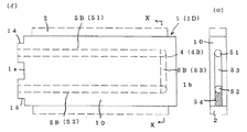
本発明による熱交換体の第二実施例を第一実施例と相違する点について説明すると、貫通タイプ4Aに代えて内部通路4が途中で折返しているリターンタイプ4Bであり、リターンタイプ4Bの直線式U字路5Bを採用するものであり、該U字路5Bは図3−1の如く金属体10の一端側1aから途中まで達する直線路5の第一通路51と第二通路52、及び両通路51,52の先部側において連通する連絡路53とから成り、第一通路51と第二通路52が適宜間隔を有して平行し、一端側1aに接続口14と接続口15とを一体に設けている。
連絡路53の形成手段とした、電極先部が可変可能な放電加工を用いて直接形成することも可能であるが、図3−2の如く金属体10の外部から第一通路51と第二通路52に連通する穴を設け、不用部に盲栓54をすることも可能である。
The difference between the second embodiment of the heat exchanger according to the present invention and the first embodiment will be described. Instead of the
Although it is possible to directly form the connecting
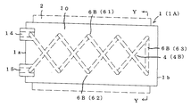
本発明による熱交換体の第三実施例を第二実施例と相違する点について説明すると、リターンタイプ4Bの直線式U字路5Bに代えて螺旋式U字路6Bを採用するものであり、該U字路6Bは図4−1の如く金属体10の一端側1aから途中まで達する螺旋路6の第一通路61と第二通路62、及び両通路61,62の先部側において連通する連絡路63から成り、第一通路61と第二通路62は180度の位相を異にして形成され、対抗位置にある第一通路61と第二通路62との端部を連絡路63で繋ぐものであり、一端側1aに接続口14と接続口15とを一体に設けている。
連絡路63の形成手段とした、電極先部が可変可能な放電加工を用いて直接形成することも可能であるが、図4−2の如く金属体10の外部から第一通路61と第二通路62に連通する穴を設け、不用部に盲栓64をすることも可能である。
The third embodiment of the heat exchange element according to the present invention will be described in terms of differences from the second embodiment. Instead of the straight U-shaped path 5B of the
Although it is possible to directly form the connecting
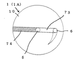
本発明による熱交換体の第四実施例を、第二及び第三実施例と相違する点について説明すると、リターンタイプ4Bとして複合式U字路7Bを採用するものであり、該U字路7Bは図5−1の如く、金属体10の一端側1aから途中まで達する直線路5と、同じ一端側1aから途中まで達する螺旋路6、及び両路5,6の先部側において連通する連絡路73とから成り、直線路5と螺旋路6との端部を連絡路73で繋ぐものであり、一端側1aに接続口14と接続口15とを一体に設けている。
連絡路73の形成手段とした、電極先部が可変可能な放電加工を用いて直接形成することも可能であるが、図5−2の如く金属体10の外部から直線路5と螺旋路6に連通する穴を設け、不用部に盲栓74をすることも可能である。
この複合式U字路7Bは、螺旋路6を通過する間に熱交換を多くし、熱交換を略完了した熱媒体Fを直線路5にて早く戻す場合に有益である。
The fourth embodiment of the heat exchange element according to the present invention will be described in terms of differences from the second and third embodiments. A composite U-junction 7B is adopted as the
Although it is possible to directly form the connecting
The composite U-shaped path 7B is useful when heat exchange is increased while passing through the
本発明による熱交換体の第五実施例を、第二乃至第四実施例と相違する点について説明すると、内部通路4を二路以上備えている複数路タイプ4Cであり、その複数路タイプ4Cの内、図6の如く直線式複数路5Cを採用したものであり、該複数路5Cは金属体10の一端側1aから他端側1bに抜ける直線路5の第一通路51と第二通路52とを適宜間隔を有して複数備え、第一通路51の一端側に接続口14を、他端側に接続口15を一体に設け、第二通路52の一端側に接続口24を、他端側に接続口25を一体に設け、熱交換ユニットや熱交換システムの熱交換回路Pに接続可能となる。
The fifth embodiment of the heat exchanger according to the present invention will be described in terms of differences from the second to fourth embodiments. The fifth embodiment is a
本発明による熱交換体の第六実施例を、第五実施例と相違する点について説明すると、複数路タイプ4Cとして螺旋式複数路6Cを採用したものであり、該複数路6Cは図7の如く、金属体10の一端側1aから他端側1bに抜ける螺旋路6の第一通路61と第二通路62とを適宜位相を異にして複数備え、第一通路61の一端側に接続口14を、他端側に接続口15を一体に設け、第二通路62の一端側に接続口24を、他端側に接続口25を一体に設け、熱交換回路Pと接続可能となるものであり、螺旋路6を例えば二路備える場合、180度の位相で形成し、三路備える場合、120度の位相で形成し、四路備える場合、90度の位相で形成する。
The sixth embodiment of the heat exchange element according to the present invention will be described in terms of the difference from the fifth embodiment. The
本発明による熱交換体の第七実施例を、第五及び第六実施例と相違する点について説明すると、複数路タイプ4Cとして複合式複数路7Cを採用したものであり、該複数路7Cは図8の如く、金属体10の一端側1aから他端側1bに抜ける直線路5と螺旋路6との何れか一方を複数備え、例えば直線路5の一端側に接続口14を、他端側に接続口15を一体に設け、螺旋路6の一端側に接続口24を、他端側に接続口25を一体に設け、熱交換回路Pと接続可能となるものである。
The seventh embodiment of the heat exchanger according to the present invention will be described in terms of the differences from the fifth and sixth embodiments. The
貫通タイプ4A(直線式貫通路5A、螺旋式貫通路6A)の熱交換体1は、単独でも使用可能であるが、2個以上を接続して後記する本発明の熱交換ブロック9を構成することが多い。
リターンタイプ4B(直線式U字路5B、螺旋式U字路6B、複合式U字路7B)の熱交換体1は、単独でも使用可能であるが、2個以上を接続して後記する本発明の熱交換ブロック9を構成することが多い。
複数路タイプ4C(直線式複数路5C、螺旋式複数路6C、複合式複数路7C)の熱交換体1は、単独でも使用可能であるが、2個以上を接続して後記する本発明の熱交換ブロック9を構成することが多い。
The
The
The
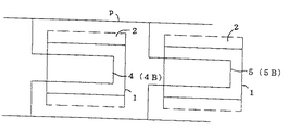
本発明における熱交換器の内、熱交換器20を構成する熱交換ブロック9において本発明の熱交換体1を直列接続するものであり、例えば図9−1は貫通タイプ4Aの内部通路4、特に螺旋式貫通路6Aを備えた熱交換体1を管路pにて直列接続し、図9−2はリターンタイプ4Bの内部通路4、特に直線式U字路5Bを備えた熱交換体1を管路pにて直列接続し、図9−3は螺旋式貫通路6Aを備えた熱交換体1と、直線式U字路5Bを備えた熱交換体1とを管路pにて直列接続するものである。
Among the heat exchangers in the present invention, the
本発明による熱交換器の内、熱交換器20を構成する熱交換ブロック9において本発明の熱交換体1を並列接続するものであり、例えば図10−1は貫通タイプ4Aの内部通路4、特に螺旋式貫通路6Aを備えた熱交換体1を管路pにて並列接続し、図10−2はリターンタイプ4Bの内部通路4、特に直線式U字路5Bを備えた熱交換体1を管路pにて並列接続し、図10−3は螺旋式貫通路6Aを備えた熱交換体1と、直線式U字路5Bを備えた熱交換体1とを管路pにて並列接続するものである。
Among the heat exchangers according to the present invention, the
熱交換器20は熱交換ブロック9のみにて構成する以外に、管路pに膨張弁P2を接続したり、熱交換ブロック9に相対して送風器P4を備える場合もある。
螺旋式貫通路6Aの代りに直線式貫通路5Aを採用することも可能であるし、直線式U字路5Bの代りに螺旋式U字路6Bや複合式U字路7Bを採用することも可能である。
貫通タイプ4Aとリターンタイプ4Bの選択、及び接続方法は、熱交換器20の大きさやデザインに合わせて選択する。
熱交換ブロック9は、1個の熱交換体1による熱交換率に限界があるため、2個以上の熱交換体1を用いる。
In addition to the
It is also possible to adopt a straight-type through
The selection of the
Since the heat exchange block 9 has a limit in the heat exchange rate of one
本発明による熱交換ユニットの第一実施例を図11−1に基づき説明すると、熱交換回路Pに本発明の熱交換体1と熱交換器20との少なくとも一つを用いるものであり、例えば熱交換回路Pの管路pに圧縮機P1と膨張弁P2と受液器P3とを接続すると共に、熱交換ブロック9に送風器P4を備えた熱交換器20を蒸発器N1、及び凝縮器N2として接続し、蒸発器N1と凝縮器N2とを空冷するもので、代表的なものとしてエアコンがある。
熱交換ユニットがエアコンの場合、熱媒体Fは冷媒で、被媒体Gは室内空気となり、冷媒は蒸発器N1を通過する間に気化して室内空気を冷却し、気化した冷媒は圧縮機P1で圧縮され、凝縮器N2を通過する間に室外空気で冷却されて液化する。
尚、蒸発器N1を通過する間に失う熱エネルギーと、室内空気の冷却エネルギーとはバランスしている。
A first embodiment of the heat exchange unit according to the present invention will be described with reference to FIG. 11A. The heat exchange circuit P uses at least one of the
When the heat exchange unit is an air conditioner, the heat medium F is a refrigerant, the medium G is room air, the refrigerant evaporates while passing through the evaporator N1, cools the room air, and the vaporized refrigerant is compressed by the compressor P1. It is compressed and cooled with outdoor air while passing through the condenser N2 and liquefied.
The heat energy lost while passing through the evaporator N1 is balanced with the cooling energy of the room air.
本発明による熱交換ユニットの第二実施例を、第一実施例と相違する点について説明すると、図11−2の如く熱交換回路Pの管路pに圧縮機P1と膨張弁P2と受液器P3とを接続すると共に、熱交換ブロック9に送風器P4を備えた熱交換器20を蒸発器N1として、また液冷式の熱交換器20を凝縮器N2として用い、蒸発器N1を空冷に、凝縮器N2を液冷にするもので、そのことにより凝縮器N2における熱交換器20の温度は液体Wにて下がり、又は上がる。
The second embodiment of the heat exchange unit according to the present invention will be described in terms of differences from the first embodiment. As shown in FIG. 11-2, the compressor P1, the expansion valve P2, and the liquid receiver are connected to the pipe p of the heat exchange circuit P. The
本発明による熱交換ユニットの第三実施例を、第一及び第二実施例と相違する点について説明すると、図11−3の如く熱交換回路Pの管路pに圧縮機P1と膨張弁P2と受液器P3とを接続すると共に、熱交換器20を液冷式の蒸発器N1と凝縮器N2として用い、蒸発器N1の液冷回路Qに熱交換器20を放熱器N6として用いるものであり、そのことにより蒸発器N1と凝縮器N2における熱交換器20の温度は液体Wにて下がり、又は上り、放熱器N6の熱交換器20は熱を放出する。
When the third embodiment of the heat exchange unit according to the present invention is different from the first and second embodiments, the compressor P1 and the expansion valve P2 are connected to the pipe p of the heat exchange circuit P as shown in FIG. And the liquid receiver P3, the
本発明による熱交換システムの第一実施例を自動車において説明すると、図12−1の如くエンジンP6の液冷回路Qと、室内の熱交換回路Pとを備え、液冷回路QにポンプP5と熱交換器20から成る空冷式のラジエーターN3と吸熱器N4とを接続し、熱交換回路Pに圧縮機P1と受液器P3と切換弁P7とを接続すると共に、本発明の熱交換体1と熱交換器20の少なくとも一方を蒸発器N1と凝縮器N2と吸熱器N4として接続するものであり、吸熱器N4は熱交換回路Pの熱エネルギーを液冷回路Qに伝える。
自動車用の熱交換システムにあっては、本発明の熱交換体1を単独で用いることは少なく、その多くは本発明の熱交換体1から成る熱交換ブロック9の熱交換器20を用いる。
A first embodiment of the heat exchange system according to the present invention will be described in an automobile. As shown in FIG. 12A, a liquid cooling circuit Q of an engine P6 and an indoor heat exchange circuit P are provided. The air-cooled radiator N3 comprising the
In the heat exchange system for automobiles, the
熱交換システムの第二実施例を、第一実施例と相違する点について説明すると、図12−2の如く熱交換回路Pに本発明の熱交換器20を吸熱器N4とエアコンN7とし接続し、エンジンP6の液冷回路Qに熱交換器20をラジエーターN3とヒーターN5として接続するものであり、吸熱器N4の前後にラジエーターN3を配置している。
この熱交換システムは、熱源となるエンジンP6を備えた車両、航空機、船舶等に有効である。
The difference between the second embodiment of the heat exchange system and the first embodiment will be described. The
This heat exchange system is effective for a vehicle, an aircraft, a ship, and the like provided with an engine P6 serving as a heat source.
リターンタイプ4Bの連絡路53,63,73は、電極先部の向きを自在にした特殊電極を用いて直接放電加工することも可能であるが、図3−1(ロ)の如く金属体10の一端側1aから途中まで第一通路51と第二通路52を形成し、外部から両通路51,52に連通する連絡路53を穿設し、不用部を盲栓54で塞いだり、図4−2の如く金属体10の一端側1aから途中まで第一通路61と第二通路62を形成し、外部から両通路61,62に連通する連絡路63を穿設し、不用部を盲栓64で塞いだり、図5−2の如く金属体10の一端側1aから途中まで直線路5と螺旋路6を形成し、外部から両路5,6に連通する連絡路73を穿設し、不用部を盲栓74で塞ぐことも可能である。
また、リターンタイプ4Bの内部通路4として、図3−2の如く金属体10の一端側1aから途中まで第一通路51と第二通路52を形成し、他端側1bに中空部21を設け、該中空部21に嵌挿する挿入体12に連絡路53を形成しておき、挿入体12を中空部21に蜜嵌することも可能である。
The
As the
螺旋路6は、金属体10に−極の電圧を、コイル状電極に+極の電圧を印加し、コイル状電極を金属体10の中心軸方向に沿って一端より内部に放電加工しながら進入して形成する場合、そのピッチは、放電加工で形成し得る加工間隙に関係する。例えば、螺旋ピッチを30mmとすると、通路長さは直線式に比べて概ね60倍となる。即ち、少ないスペースに大きな熱交換能力を集積できる。
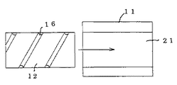
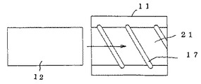
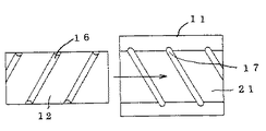
螺旋路6はコイル状電極による放電加工に限定されるものではなく、例えば図14−1の如く金属体10を筒体11と、筒体中空部21に嵌挿する挿入体12とから構成し、挿入体12の外周面に外周螺旋溝16を穿設するか、図14−2の如く筒体11の内周面に内周螺旋溝17を雌ねじの様に穿設し、更に、図14−3の如く筒体11の内周面と挿入体12の外周面とに螺旋溝16,17を穿設しても形成し得る。
The
The
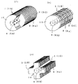
熱交換体1の形状は、図13−1(イ)の如く円柱状熱交換体1A、図13−1(ロ)の如く多角柱状熱交換体1B、図13−1(ハ)の如く十字状熱交換体1Cを初め、図13−2の如く板状熱交換体1D、図13−3の如くドーナツ状熱交換体1E等、熱交換器20や熱交換ユニットの用途等に合わせて適宜形状を採用することが可能である。
円柱状熱交換体1Aと多角柱状熱交換体1Bは、螺旋路6の内部通路4の形成に適するし、板状熱交換体1Dとドーナツ状熱交換体1Eにあっては、厚さ方向に螺旋路6を形成する必要がある。
The shape of the
The columnar
亜鉛合金としては、例えばZAS、ZAPREC(何れも商品名)、その他の亜鉛合金を選択することができる。ZAPRECは優れた放電特性と鋼・アルミの2〜4倍の高速加工性能(快削性)、及び溶接性に優れている。
小幅溝部8aの溝幅Lを放熱部厚さsより小さくすると、一定範囲に放熱部3、特にピン放熱部3Aを多数形成することができる。
As the zinc alloy, for example, ZAS, ZAPREC (both are trade names), and other zinc alloys can be selected. ZAPREC has excellent discharge characteristics, high-speed machining performance (free machining) 2 to 4 times that of steel and aluminum, and excellent weldability.
When the groove width L of the narrow groove portion 8a is made smaller than the heat radiation portion thickness s, a large number of
直線式複数路5Cにおける直線路5の数と、螺旋式複数路6Cにおける螺旋路6の数、及び複合式複数路7Cにおける直線路5と螺旋路6との組み合わせは、金属体10の形状に応じて自由である。
内部通路4の端部に設ける接続口14,15は、金属体10に直接設けることも可能であるが、螺旋式貫通路6Aにあっては別体に備えることが好ましい。
本発明の熱交換体1と熱交換器20は、排ガスの工程で使用するレキュピレーター、エレメントチューブ、エコノメヤーとして、或は熱回収器、特に排ガス用熱回収器のロスナイ、エコサーモ、ルームクーラーとしても使用可能である。
The number of the
Although the
The
熱交換ブロック9における熱交換体1は、実施形態の直列接続と並列接続に限定されるものではなく、直列接続と並列接続とを併用することも可能である。又、熱交換体1の種類は螺旋式貫通路6Aと直線式U字路5Bとに限定されるものではなく、他の貫通タイプ4Aやリターンタイプ4Bを用いることも可能であるし、複数路タイプ4Cも用いることも可能である。
The
1,1A,1B,1C,1D,1E 熱交換体
1a 一端側、1b 他端側
10 金属体、11 筒体、12 挿入体、21 中空部
2 熱交換部
3 放熱部、13 密集放熱部
3A ピン状放熱部、3B 板状放熱部、3C 環状放熱部
4 内部通路
4A 貫通タイプ、4B リターンタイプ、4C 複数路タイプ
5 直線路、5A 直線式貫通路、5B 直線式U字路、5C 直線式複数路
6 螺旋路、6A 螺旋式貫通路、6B 螺旋式U字路、6C 螺旋式複数路
7B 複合式U字路、7C 複合式複数路
16 外周螺旋溝、17 内周螺旋溝
51,61 第一通路、52,62 第二通路、53,63,73 連絡路
54,64,74 盲栓
8 溝部、8a 小幅溝部、8b 広幅溝部
14,15,24,25 接続口
9,M 熱交換ブロック
m1 プレート、m2 補強板、m3 放熱フイン、m4 銅パイプ
m5 連結パイプ、m6 半田
20,N 熱交換器、N1 蒸発器、N2 凝縮器、N3 ラジエーター
N4 吸熱器、N5 ヒーター、N6 放熱器、N7 エアコン
P 熱交換回路、p 管路
P1 圧縮機、P2 膨張弁、P3 受液器、P4 送風器、P5 ポンプ
P6 エンジン、P7 切換弁
Q 液冷回路
F 熱媒体、G 被媒体、W 液体
H 金属体長さ、L 溝幅
s 放熱部厚さ、t 放熱部高さ、h 放熱部長さ
1, 1A, 1B, 1C, 1D, 1E Heat exchanger 1a One end side, 1b The other end side 10 Metal body, 11 Cylinder body, 12 Insert body, 21 Hollow part 2 Heat exchange part 3 Heat radiation part, 13 Dense heat radiation part 3A Pin-shaped heat radiating section, 3B Plate-shaped heat radiating section, 3C Annular heat radiating section 4 Internal passage 4A Through type 4B Return type 4C Multi-path type 5 Straight path 5A Straight through path 5B Straight U-shaped path 5C Straight type Multiple path 6 Spiral path, 6A Spiral through path, 6B Spiral U path, 6C Spiral multiple path 7B Composite U path, 7C Composite multiple path 16 Outer spiral groove, 17 Inner spiral groove 51, 61 One passage, 52, 62 Second passage, 53, 63, 73 Connecting passage 54, 64, 74 Blind plug 8 Groove portion, 8a Narrow groove portion, 8b Wide groove portion 14, 15, 24, 25 Connection port 9, M Heat exchange block m1 Plate, m2 reinforcing plate, m Heat radiation fin, m4 copper pipe m5 connection pipe, m6 solder 20, N heat exchanger, N1 evaporator, N2 condenser, N3 radiator N4 heat absorber, N5 heater, N6 heat radiator, N7 air conditioner P heat exchange circuit, p pipe line P1 compressor, P2 expansion valve, P3 receiver, P4 blower, P5 pump P6 engine, P7 switching valve Q liquid cooling circuit F heat medium, G medium, W liquid H metal body length, L groove width s heat dissipation part Thickness, t Heat sink height, h Heat sink length
Claims (9)
An automobile, train, or the like, characterized in that a heat exchange circuit (P) is configured using at least one of the heat exchanger (1) according to claims 1 to 6 and the heat exchanger (20) according to claim 7. Heat exchange system for aircraft, ships, etc.
Priority Applications (1)
| Application Number | Priority Date | Filing Date | Title |
|---|---|---|---|
| JP2004169664A JP2005351488A (en) | 2004-06-08 | 2004-06-08 | Heat exchanging member, heat exchanger, heat exchanging unit and heat exchanging system |
Applications Claiming Priority (1)
| Application Number | Priority Date | Filing Date | Title |
|---|---|---|---|
| JP2004169664A JP2005351488A (en) | 2004-06-08 | 2004-06-08 | Heat exchanging member, heat exchanger, heat exchanging unit and heat exchanging system |
Publications (2)
| Publication Number | Publication Date |
|---|---|
| JP2005351488A true JP2005351488A (en) | 2005-12-22 |
| JP2005351488A5 JP2005351488A5 (en) | 2007-07-19 |
Family
ID=35586116
Family Applications (1)
| Application Number | Title | Priority Date | Filing Date |
|---|---|---|---|
| JP2004169664A Pending JP2005351488A (en) | 2004-06-08 | 2004-06-08 | Heat exchanging member, heat exchanger, heat exchanging unit and heat exchanging system |
Country Status (1)
| Country | Link |
|---|---|
| JP (1) | JP2005351488A (en) |
Cited By (2)
| Publication number | Priority date | Publication date | Assignee | Title |
|---|---|---|---|---|
| EP3193125A1 (en) * | 2016-01-14 | 2017-07-19 | Hamilton Sundstrand Corporation | Heat exchanger channels |
| CN115447337A (en) * | 2022-08-16 | 2022-12-09 | 浙江银轮新能源热管理系统有限公司 | Integrated heat exchange device and thermal management system |
Citations (11)
| Publication number | Priority date | Publication date | Assignee | Title |
|---|---|---|---|---|
| JPS4826662A (en) * | 1971-08-10 | 1973-04-07 | ||
| JPS52128068A (en) * | 1976-04-21 | 1977-10-27 | Hitachi Ltd | Manufacture of cooling piece for semiconductor rectifying device |
| JPS5447063U (en) * | 1977-09-09 | 1979-04-02 | ||
| JPS6341791A (en) * | 1986-08-06 | 1988-02-23 | Komatsu Ltd | Skived-finned heat exchanger |
| JPH03251685A (en) * | 1990-02-28 | 1991-11-11 | Suzuki Motor Corp | Heat exchanging device |
| JPH08210793A (en) * | 1995-02-01 | 1996-08-20 | Nippondenso Co Ltd | Heat exchanger |
| JPH09159385A (en) * | 1995-12-07 | 1997-06-20 | Nippon Alum Co Ltd | Cooling jacket and manufacture thereof |
| JPH11153368A (en) * | 1997-11-25 | 1999-06-08 | Shimadzu Corp | Cooling device for aircraft |
| JP2002362359A (en) * | 2001-06-07 | 2002-12-18 | Hitachi Ltd | Air conditioner for rolling stock |
| JP2003136343A (en) * | 2001-11-06 | 2003-05-14 | Osaka Prefecture | Bending hole processing method |
| JP2003314927A (en) * | 2002-04-18 | 2003-11-06 | Matsushita Electric Ind Co Ltd | Heat exchanger and refrigerating cycle device using the same |
-
2004
- 2004-06-08 JP JP2004169664A patent/JP2005351488A/en active Pending
Patent Citations (11)
| Publication number | Priority date | Publication date | Assignee | Title |
|---|---|---|---|---|
| JPS4826662A (en) * | 1971-08-10 | 1973-04-07 | ||
| JPS52128068A (en) * | 1976-04-21 | 1977-10-27 | Hitachi Ltd | Manufacture of cooling piece for semiconductor rectifying device |
| JPS5447063U (en) * | 1977-09-09 | 1979-04-02 | ||
| JPS6341791A (en) * | 1986-08-06 | 1988-02-23 | Komatsu Ltd | Skived-finned heat exchanger |
| JPH03251685A (en) * | 1990-02-28 | 1991-11-11 | Suzuki Motor Corp | Heat exchanging device |
| JPH08210793A (en) * | 1995-02-01 | 1996-08-20 | Nippondenso Co Ltd | Heat exchanger |
| JPH09159385A (en) * | 1995-12-07 | 1997-06-20 | Nippon Alum Co Ltd | Cooling jacket and manufacture thereof |
| JPH11153368A (en) * | 1997-11-25 | 1999-06-08 | Shimadzu Corp | Cooling device for aircraft |
| JP2002362359A (en) * | 2001-06-07 | 2002-12-18 | Hitachi Ltd | Air conditioner for rolling stock |
| JP2003136343A (en) * | 2001-11-06 | 2003-05-14 | Osaka Prefecture | Bending hole processing method |
| JP2003314927A (en) * | 2002-04-18 | 2003-11-06 | Matsushita Electric Ind Co Ltd | Heat exchanger and refrigerating cycle device using the same |
Cited By (3)
| Publication number | Priority date | Publication date | Assignee | Title |
|---|---|---|---|---|
| EP3193125A1 (en) * | 2016-01-14 | 2017-07-19 | Hamilton Sundstrand Corporation | Heat exchanger channels |
| US11112183B2 (en) | 2016-01-14 | 2021-09-07 | Hamilton Sundstrand Corporation | Heat exchanger channels |
| CN115447337A (en) * | 2022-08-16 | 2022-12-09 | 浙江银轮新能源热管理系统有限公司 | Integrated heat exchange device and thermal management system |
Similar Documents
| Publication | Publication Date | Title |
|---|---|---|
| US7921904B2 (en) | Heat exchanger and method | |
| RU2287755C2 (en) | Heat exchanger and cooling system | |
| US7621320B2 (en) | Internal heat exchanger | |
| RU2227883C2 (en) | Two-phase heat-exchanger with liquid cooling (variants) | |
| US20110094258A1 (en) | Heat exchanger and air conditioner provided with heat exchanger | |
| CN1664324A (en) | thermoelectric generator | |
| WO2007013439A1 (en) | Heat exchanger | |
| JP2015017776A5 (en) | ||
| JP4561305B2 (en) | Heat exchanger | |
| US11268769B2 (en) | Heat exchanger | |
| US7546867B2 (en) | Spirally wound, layered tube heat exchanger | |
| JP3911604B2 (en) | Heat exchanger and refrigeration cycle | |
| US20070056718A1 (en) | Heat exchanger and duplex type heat exchanger | |
| JP2010139201A (en) | Cold storage device and vehicle air conditioner using the same | |
| JP2005127529A (en) | Heat exchanger | |
| JP2005351488A (en) | Heat exchanging member, heat exchanger, heat exchanging unit and heat exchanging system | |
| KR20070102172A (en) | Heat exchanger with condenser and oil cooler | |
| JP5772608B2 (en) | Heat exchanger | |
| JP2004183960A (en) | Heat exchanger | |
| JP2002228387A (en) | Heat exchanger | |
| JP2004340485A (en) | Complex heat exchanger | |
| WO2019208041A1 (en) | Heat exchanger | |
| KR100575278B1 (en) | Heat pipe with capillary heat pipe | |
| JP2005024188A (en) | Heat exchanger | |
| CN114341587A (en) | Heat exchanger and refrigeration cycle device |
Legal Events
| Date | Code | Title | Description |
|---|---|---|---|
| A521 | Written amendment |
Effective date: 20070606 Free format text: JAPANESE INTERMEDIATE CODE: A523 |
|
| A621 | Written request for application examination |
Effective date: 20070606 Free format text: JAPANESE INTERMEDIATE CODE: A621 |
|
| A977 | Report on retrieval |
Effective date: 20100521 Free format text: JAPANESE INTERMEDIATE CODE: A971007 |
|
| A131 | Notification of reasons for refusal |
Free format text: JAPANESE INTERMEDIATE CODE: A131 Effective date: 20100601 |
|
| A02 | Decision of refusal |
Free format text: JAPANESE INTERMEDIATE CODE: A02 Effective date: 20101019 |


