JP2005347303A - Thermocompression bonding machine - Google Patents
Thermocompression bonding machine Download PDFInfo
- Publication number
- JP2005347303A JP2005347303A JP2004161570A JP2004161570A JP2005347303A JP 2005347303 A JP2005347303 A JP 2005347303A JP 2004161570 A JP2004161570 A JP 2004161570A JP 2004161570 A JP2004161570 A JP 2004161570A JP 2005347303 A JP2005347303 A JP 2005347303A
- Authority
- JP
- Japan
- Prior art keywords
- thermocompression bonding
- heat insulating
- bonding apparatus
- fluid passage
- heat
- Prior art date
- Legal status (The legal status is an assumption and is not a legal conclusion. Google has not performed a legal analysis and makes no representation as to the accuracy of the status listed.)
- Pending
Links
Images


Landscapes
- Electric Connection Of Electric Components To Printed Circuits (AREA)
Abstract
Description
本発明は、電子部品や基板などのワークを熱圧着して接合する熱圧着装置に関するものである。 The present invention relates to a thermocompression bonding apparatus that joins a workpiece such as an electronic component or a substrate by thermocompression bonding.
電子部品や基板などのワークを相互に接合する方法としては、熱圧着による方法が知られている。この方法は、ワークの接合部を被接合部に対して所定の荷重で押しながらワークを加熱することにより、接合部を半田もしくは熱硬化性接着剤により接合するものである。従来の熱圧着装置は、図4に示す様に、高温に加熱した状態のヒーターツール103をワーク105に短時間押し当てて接合し、これを繰り返し行う様に構成されている。その場合、ヒーターツール103の熱が圧着装置本体に伝達されると、圧着装置本体の精度等に悪影響が出るため、ヒーターツール103から熱圧着装置本体側(保持部材101側)へ伝わる熱を断熱するために、断熱材102を備えている。
しかしながら、上記の従来例では、断熱材102として樹脂性の断熱材を使用しているために、経時熱劣化を起こし、組み付け精度が変化(熱収縮/割れ)する場合がある。また、耐久性においても、370℃という高温のもとで、繰り返し圧力を加えるために、断熱材102が炭化し、30日間に1回程度の割合で断熱材の耐久の限界に至り割れが生じるため、断熱材102の交換が必要であった。また、工程管理上では、熱圧着されたワークの定時抜き取りによる手動電気検査及び、圧着面の感圧紙チェックを実施しているが、断熱材の熱劣化収縮等の精度変化による圧着不良は検出が困難な状況で、主に断熱材を定期的に交換することで対応していた。
However, in the above conventional example, since a resinous heat insulating material is used as the
そこで、本発明は、上記事情に鑑みてなされたものであり、その目的は、ヒーターツールを高温に加熱しても熱圧着面に加わる圧力を均一に保ちつつ、ヒーターツールから装置本体へ伝わる熱を断熱することができるようにすることである。 Therefore, the present invention has been made in view of the above circumstances, and its purpose is to provide heat transmitted from the heater tool to the apparatus main body while maintaining a uniform pressure applied to the thermocompression bonding surface even when the heater tool is heated to a high temperature. Is to be able to insulate.
上述した課題を解決し、目的を達成するために、本発明に係わる熱圧着装置は、発熱源を備える加熱部材をワークに押し付け、該ワークを熱圧着する熱圧着装置において、前記加熱部材を前記熱圧着装置の本体部に支持するための支持部材と、該支持部材と前記加熱部材との間に配置され、冷却媒体を通過させるための第1の流体通路を備える断熱部材と、を具備することを特徴とする。 In order to solve the above-described problems and achieve the object, a thermocompression bonding apparatus according to the present invention is a thermocompression bonding apparatus that presses a heating member having a heat generation source against a workpiece and thermocompression-bonds the workpiece. A support member for supporting the main body portion of the thermocompression bonding apparatus; and a heat insulating member that is disposed between the support member and the heating member and includes a first fluid passage for allowing a cooling medium to pass therethrough. It is characterized by that.
また、この発明に係わる熱圧着装置において、前記第1の流体通路を通過した冷却媒体は、前記断熱部材に接続された配管により外部に排出されることを特徴とする。
また、この発明に係わる熱圧着装置において、前記支持部材は、前記第1の流体通路に連通する第2の流体通路を備え、前記冷却媒体は、前記第2の流体通路から前記第1の流体通路に供給されることを特徴とする。
In the thermocompression bonding apparatus according to the present invention, the cooling medium that has passed through the first fluid passage is discharged to the outside through a pipe connected to the heat insulating member.
In the thermocompression bonding apparatus according to the present invention, the support member includes a second fluid passage that communicates with the first fluid passage, and the cooling medium is supplied from the second fluid passage to the first fluid. It is supplied to the passage.
また、この発明に係わる熱圧着装置において、前記断熱部材は、前記加熱部材との間の中央部に空間を備え、前記支持部材と前記断熱部材と前記加熱部材とはそれらの端部で互いに固定されていることを特徴とする。 Further, in the thermocompression bonding apparatus according to the present invention, the heat insulating member includes a space in a central portion between the heating member and the support member, the heat insulating member, and the heating member are fixed to each other at their end portions. It is characterized by being.
また、この発明に係わる熱圧着装置において、前記冷却媒体は空気であることを特徴とする。 In the thermocompression bonding apparatus according to the present invention, the cooling medium is air.
また、この発明に係わる熱圧着装置において、前記断熱部材は、金属材料から形成されていることを特徴とする。 In the thermocompression bonding apparatus according to the present invention, the heat insulating member is made of a metal material.
本発明によれば、ヒーターツールを高温に加熱しても熱圧着面に加わる圧力を均一に保ちつつ、ヒーターツールから装置本体へ伝わる熱を断熱することが可能となる。 ADVANTAGE OF THE INVENTION According to this invention, even if a heater tool is heated to high temperature, it becomes possible to insulate the heat | fever transmitted from a heater tool to an apparatus main body, maintaining the pressure added to a thermocompression bonding surface uniformly.
以下、本発明の好適な一実施形態について、図面を参照して詳細に説明する。 Hereinafter, a preferred embodiment of the present invention will be described in detail with reference to the drawings.
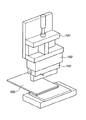
図1は本発明の一実施形態に係わる電子部品のワーク熱圧着装置の斜視図であり、図2は熱圧着ヘッドの正面断面図、図3は熱圧着ヘッドの保持部部分の側断面図である。 1 is a perspective view of a thermocompression bonding apparatus for electronic parts according to an embodiment of the present invention, FIG. 2 is a front sectional view of a thermocompression bonding head, and FIG. 3 is a side sectional view of a holding portion of the thermocompression bonding head. is there.
まず、図1を参照してワーク熱圧着装置の構造について説明する。 First, the structure of the workpiece thermocompression bonding apparatus will be described with reference to FIG.
圧着作業を行うための受け台9の上に、プリント基板5−1が置かれ、重ねて異方性導電膜5−3が載せられ、フレキシブル基板5−2が重ねられる。これらのプリント基板5−1、フレキシブル基板5−2、異方性導電膜5−3を合わせてワーク5と呼ぶことにする。このワーク5の上方にあり、Z軸方向に昇降するシリンダロッド20には、熱圧着ヘッド16を保持する保持部1が固定されている。熱圧着ヘッド16は、保持部1に装着された断熱ブロック2と、断熱ブロック2の下端部に装着されたヒーターツール(加熱部材)3とを備えている。シリンダロッド20がZ軸方向に駆動されることによって、ヒーターツール3がワーク5に対して降下する。そして、ワーク5のフレキシブル基板5−2を所定の荷重で押圧しながら、異方性導電膜5−3を加熱することにより、フレキシブル基板5−2がプリント基板5−1に熱圧着される。
A printed circuit board 5-1 is placed on a cradle 9 for performing a crimping operation, and an anisotropic conductive film 5-3 is placed thereon, and a flexible board 5-2 is placed thereon. The printed circuit board 5-1, the flexible circuit board 5-2, and the anisotropic conductive film 5-3 are collectively referred to as a
図2及び図3を参照して、熱圧着ヘッドの構造について説明する。 The structure of the thermocompression bonding head will be described with reference to FIGS.
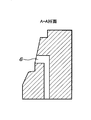
熱圧着ヘッドの正面断面図である図2及び側断面図である図3に示す様に、保持部1の内部には、通気孔6が設けられており、エアーを外部から流し込むための通路を形成している。通気孔6は、正面から下に向かって保持部1を貫通し、断熱ブロック2の空気溜まり(凹形状部2a)まで達している。断熱ブロック2は、保持部1と接する側の中央部分に空気溜まりとなる凹形状部2aを備えている。更に、通気孔7は、凹形状部2aとともに、保持部1の側面の開口部7aに連通する通路を形成しており、通気孔6から入ったエアーを配管8を介して外部に開放している。なお、配管8の後端には不図示のエアー吸引源が接続されている。この構成によれば、断熱ブロック2に従来のような樹脂材料でなく金属材料を使用した場合でも、断熱ブロック2内に常時冷却エアーを流すことにより、ヒーターツール3からの熱を断熱ブロック2と保持部1で分断することができ、ヒーターツール3の熱が熱圧着装置本体に伝達されることが防止される。
As shown in FIG. 2, which is a front sectional view of the thermocompression bonding head, and FIG. 3, which is a side sectional view, a
なお、保持部1と断熱ブロック2とヒーターツール3とをそれらの両端で固定して高温に加熱すると、熱膨張によりヒーターツール3の先端部中央が膨らんでしまう。これを回避するために、断熱ブロック2とヒーターツール3の間に切り欠いた空間2bを設けるとともに、エアーを保持部1の中央から流し込んで冷却する。これにより、ヒーターツール3の先端部中央の膨らみを緩和することができ、ヒーターツール3の先端部の全面でワーク5を均一に熱圧着することが出来る。
In addition, if the holding |
更に、図4に示す従来の断熱ブロック102では、樹脂系の断熱材を使用していることにより、経時熱劣化で収縮してヒーターツール3の先端位置の精度変化が起こったり、断熱ブロック2が欠けたりしていたのに対して、本実施形態の断熱ブロック2では、金属で形成しているので、繰り返し動作をしても、先端位置の精度変化が起きないで熱圧着することが出来る。
Furthermore, in the conventional
また、ヒーターツール3には、ヒーター4が挿入されており、例えば先端温度200℃の温度調整をするために、ヒーターツール3の先端部に配置された熱電対10(図1参照)により温度を検出しながら、ヒーター4を例えば370℃に加熱する。そして、ヒーターツール3の先端部でワーク5を全面均一に押圧して熱圧着する。
Moreover, the heater 4 is inserted in the heater tool 3, and the temperature is adjusted by a thermocouple 10 (see FIG. 1) disposed at the tip of the heater tool 3 in order to adjust the temperature at a tip temperature of 200 ° C., for example. While detecting, the heater 4 is heated to 370 ° C., for example. And the workpiece |
以上説明したように。本実施形態に係わるワーク熱圧着装置では、保持部に通気孔を設けて空気を流し込むことで断熱ブロックを冷却し、装置本体との熱分断を図ることができる。 As explained above. In the work thermocompression bonding apparatus according to the present embodiment, the heat insulating block can be cooled by providing a ventilation hole in the holding portion and flowing air, thereby dividing the heat from the apparatus main body.
また、従来の断熱材に比べて高温に加熱しても、熱収縮/割れを生ずることなくワークを均一に熱圧着できる。 Further, even when heated to a higher temperature than conventional heat insulating materials, the workpiece can be uniformly thermocompressed without causing thermal shrinkage / cracking.
また、保持部の中央部分からの冷却機能と断熱ブロックの中央部に空間を備えたことで、ヒーターツールの圧着面中央の出っ張りを緩和し、熱圧着面の位置精度を安定化させることができる。 In addition, by providing a cooling function from the central part of the holding part and a space in the central part of the heat insulation block, it is possible to relax the protrusion at the center of the crimping surface of the heater tool and stabilize the positional accuracy of the thermocompression bonding surface. .
これにより、本装置の設置時に、圧着面の位置出しを行えば、以後調整が不要になり、生産中の調整作業等の負荷低減ができ生産性向上につながる。 As a result, if the crimping surface is positioned at the time of installation of the present apparatus, no adjustment is necessary thereafter, and the load during adjustment work during production can be reduced, leading to improved productivity.
また、排気管(配管8)は、装置外部に引き回しているので、ゴミ等の進入もなく環境の清浄度を維持したまま生産を行なうことが出来る。 Further, since the exhaust pipe (pipe 8) is routed outside the apparatus, it is possible to carry out production while maintaining the cleanliness of the environment without entering dust.
なお、上記の説明では、保持部と断熱ブロックの双方に通気孔を設けるように説明したが、断熱ブロックのみに通気孔を設けるようにしてもよい。 In the above description, the air holes are provided in both the holding portion and the heat insulating block, but the air holes may be provided only in the heat insulating block.
また、上記の説明では、冷却媒体として空気を使用する場合について説明したが、その他の気体や液体であってもよい。 In the above description, the case where air is used as the cooling medium has been described. However, other gases and liquids may be used.
1 保持部
2 断熱ブロック
3 ヒーターツール
4 ヒーター
5 ワーク
6 通気孔(供給)
7 通気孔(排出)
8 配管
9 受け台
10 熱電対
1 Holding
3 Heater tool 4
7 Vent (discharge)
8 Piping 9
Claims (6)
前記加熱部材を前記熱圧着装置の本体部に支持するための支持部材と、
該支持部材と前記加熱部材との間に配置され、冷却媒体を通過させるための第1の流体通路を備える断熱部材と、
を具備することを特徴とする熱圧着装置。 In a thermocompression bonding apparatus that presses a heating member provided with a heat source against a work and thermocompression-bonds the work,
A support member for supporting the heating member on the main body of the thermocompression bonding apparatus;
A heat insulating member that is disposed between the support member and the heating member and includes a first fluid passage for passing a cooling medium;
A thermocompression bonding apparatus comprising:
Priority Applications (1)
| Application Number | Priority Date | Filing Date | Title |
|---|---|---|---|
| JP2004161570A JP2005347303A (en) | 2004-05-31 | 2004-05-31 | Thermocompression bonding machine |
Applications Claiming Priority (1)
| Application Number | Priority Date | Filing Date | Title |
|---|---|---|---|
| JP2004161570A JP2005347303A (en) | 2004-05-31 | 2004-05-31 | Thermocompression bonding machine |
Publications (2)
| Publication Number | Publication Date |
|---|---|
| JP2005347303A true JP2005347303A (en) | 2005-12-15 |
| JP2005347303A5 JP2005347303A5 (en) | 2007-07-12 |
Family
ID=35499434
Family Applications (1)
| Application Number | Title | Priority Date | Filing Date |
|---|---|---|---|
| JP2004161570A Pending JP2005347303A (en) | 2004-05-31 | 2004-05-31 | Thermocompression bonding machine |
Country Status (1)
| Country | Link |
|---|---|
| JP (1) | JP2005347303A (en) |
Cited By (5)
| Publication number | Priority date | Publication date | Assignee | Title |
|---|---|---|---|---|
| JP2012204604A (en) * | 2011-03-25 | 2012-10-22 | Fujikoshi Mach Corp | Work sticking method and work sticking device |
| JP2014140032A (en) * | 2013-01-21 | 2014-07-31 | Vesi Switzerland Ag | Bonding head having suction member capable of heating and cooling |
| CN104282586A (en) * | 2013-07-02 | 2015-01-14 | 库利克和索夫工业公司 | Bond heads for thermocompression bonders, thermocompression bonders, and methods of operating the same |
| JP2015233138A (en) * | 2014-06-10 | 2015-12-24 | セメス株式会社Semes Co., Ltd. | Bonding head and die bonding device including the same |
| CN111390465A (en) * | 2020-01-20 | 2020-07-10 | 武汉高芯科技有限公司 | Hydraulic device for flip-chip welding |
Citations (3)
| Publication number | Priority date | Publication date | Assignee | Title |
|---|---|---|---|---|
| JPH1041355A (en) * | 1996-07-24 | 1998-02-13 | Toray Eng Co Ltd | Thermocompression bonding tool |
| JP2001060757A (en) * | 1999-06-14 | 2001-03-06 | Sharp Corp | Method for mounting external and thermocompression bonding device |
| JP2004031885A (en) * | 2002-04-30 | 2004-01-29 | Toray Eng Co Ltd | Bonding method and apparatus therefor |
-
2004
- 2004-05-31 JP JP2004161570A patent/JP2005347303A/en active Pending
Patent Citations (3)
| Publication number | Priority date | Publication date | Assignee | Title |
|---|---|---|---|---|
| JPH1041355A (en) * | 1996-07-24 | 1998-02-13 | Toray Eng Co Ltd | Thermocompression bonding tool |
| JP2001060757A (en) * | 1999-06-14 | 2001-03-06 | Sharp Corp | Method for mounting external and thermocompression bonding device |
| JP2004031885A (en) * | 2002-04-30 | 2004-01-29 | Toray Eng Co Ltd | Bonding method and apparatus therefor |
Cited By (6)
| Publication number | Priority date | Publication date | Assignee | Title |
|---|---|---|---|---|
| JP2012204604A (en) * | 2011-03-25 | 2012-10-22 | Fujikoshi Mach Corp | Work sticking method and work sticking device |
| JP2014140032A (en) * | 2013-01-21 | 2014-07-31 | Vesi Switzerland Ag | Bonding head having suction member capable of heating and cooling |
| CN104282586A (en) * | 2013-07-02 | 2015-01-14 | 库利克和索夫工业公司 | Bond heads for thermocompression bonders, thermocompression bonders, and methods of operating the same |
| JP2015233138A (en) * | 2014-06-10 | 2015-12-24 | セメス株式会社Semes Co., Ltd. | Bonding head and die bonding device including the same |
| CN111390465A (en) * | 2020-01-20 | 2020-07-10 | 武汉高芯科技有限公司 | Hydraulic device for flip-chip welding |
| CN111390465B (en) * | 2020-01-20 | 2022-03-22 | 武汉高芯科技有限公司 | Hydraulic device for flip-chip welding |
Similar Documents
| Publication | Publication Date | Title |
|---|---|---|
| KR100993079B1 (en) | Bonding apparatus | |
| RU2333622C1 (en) | Method and system of thermal connection and disconnection of components for surface mounting | |
| US7667474B2 (en) | Probe device | |
| US9338935B2 (en) | System for removing an electronic component from a substrate | |
| US7425838B2 (en) | Body for keeping a wafer and wafer prober using the same | |
| JP4986830B2 (en) | Substrate holder and method for manufacturing the same | |
| CN111344855B (en) | Chuck plate, chuck structure with chuck plate and welding device with chuck structure | |
| JP2010129890A (en) | Bonding head | |
| US20080156789A1 (en) | Platen for use with a thermal attach and detach system which holds components by vacuum suction | |
| JP2005347303A (en) | Thermocompression bonding machine | |
| JP5257149B2 (en) | Solder removing apparatus and solder removing method | |
| JP2006324581A (en) | Electronic component bonding device | |
| JP4385895B2 (en) | Bonding equipment | |
| JP2007311679A (en) | Thermocompression apparatus for electronic components | |
| CN101193498A (en) | Printed circuit board, printed circuit board assembly, manufacturing method of printed circuit board, warpage correcting method of printed circuit board and electronic device | |
| JP4733441B2 (en) | Electronic component joining equipment | |
| JPH04364090A (en) | Soldering jig | |
| JP3539826B2 (en) | Thermocompression tools | |
| JP4323419B2 (en) | Thermocompression bonding tool and thermocompression bonding apparatus | |
| JP2001358455A (en) | Thermo compression bonding device and method of electronic component | |
| US20230321925A1 (en) | Method for connecting a film to a substrate | |
| JP2006222100A (en) | Hot press heater | |
| JP2007115924A (en) | Method for manufacturing bonded structure | |
| JP2812304B2 (en) | Repair method for flip-chip type semiconductor device | |
| JP2006102761A (en) | Method for producing low melting point brazing clad plate |
Legal Events
| Date | Code | Title | Description |
|---|---|---|---|
| A521 | Written amendment |
Free format text: JAPANESE INTERMEDIATE CODE: A523 Effective date: 20070525 |
|
| A621 | Written request for application examination |
Effective date: 20070525 Free format text: JAPANESE INTERMEDIATE CODE: A621 |
|
| RD03 | Notification of appointment of power of attorney |
Effective date: 20070525 Free format text: JAPANESE INTERMEDIATE CODE: A7423 |
|
| A977 | Report on retrieval |
Effective date: 20090511 Free format text: JAPANESE INTERMEDIATE CODE: A971007 |
|
| A131 | Notification of reasons for refusal |
Effective date: 20090522 Free format text: JAPANESE INTERMEDIATE CODE: A131 |
|
| A521 | Written amendment |
Free format text: JAPANESE INTERMEDIATE CODE: A523 Effective date: 20090716 |
|
| A131 | Notification of reasons for refusal |
Free format text: JAPANESE INTERMEDIATE CODE: A131 Effective date: 20090807 |
|
| A521 | Written amendment |
Free format text: JAPANESE INTERMEDIATE CODE: A523 Effective date: 20091005 |
|
| A02 | Decision of refusal |
Effective date: 20100427 Free format text: JAPANESE INTERMEDIATE CODE: A02 |