JP2005339775A - Method for sensing transducer head position to storage medium, servo control system for positioning magnetic head proximately to surface of magnetic storage medium, method for writing longitudinal servo track in magnetic storage medium, and magnetic storage medium including longitudinal servo track - Google Patents
Method for sensing transducer head position to storage medium, servo control system for positioning magnetic head proximately to surface of magnetic storage medium, method for writing longitudinal servo track in magnetic storage medium, and magnetic storage medium including longitudinal servo track Download PDFInfo
- Publication number
- JP2005339775A JP2005339775A JP2005149525A JP2005149525A JP2005339775A JP 2005339775 A JP2005339775 A JP 2005339775A JP 2005149525 A JP2005149525 A JP 2005149525A JP 2005149525 A JP2005149525 A JP 2005149525A JP 2005339775 A JP2005339775 A JP 2005339775A
- Authority
- JP
- Japan
- Prior art keywords
- servo
- mark
- tone field
- storage medium
- track
- Prior art date
- Legal status (The legal status is an assumption and is not a legal conclusion. Google has not performed a legal analysis and makes no representation as to the accuracy of the status listed.)
- Pending
Links
Images


Classifications
-
- G—PHYSICS
- G11—INFORMATION STORAGE
- G11B—INFORMATION STORAGE BASED ON RELATIVE MOVEMENT BETWEEN RECORD CARRIER AND TRANSDUCER
- G11B5/00—Recording by magnetisation or demagnetisation of a record carrier; Reproducing by magnetic means; Record carriers therefor
- G11B5/48—Disposition or mounting of heads or head supports relative to record carriers ; arrangements of heads, e.g. for scanning the record carrier to increase the relative speed
- G11B5/58—Disposition or mounting of heads or head supports relative to record carriers ; arrangements of heads, e.g. for scanning the record carrier to increase the relative speed with provision for moving the head for the purpose of maintaining alignment of the head relative to the record carrier during transducing operation, e.g. to compensate for surface irregularities of the latter or for track following
- G11B5/584—Disposition or mounting of heads or head supports relative to record carriers ; arrangements of heads, e.g. for scanning the record carrier to increase the relative speed with provision for moving the head for the purpose of maintaining alignment of the head relative to the record carrier during transducing operation, e.g. to compensate for surface irregularities of the latter or for track following for track following on tapes
-
- G—PHYSICS
- G11—INFORMATION STORAGE
- G11B—INFORMATION STORAGE BASED ON RELATIVE MOVEMENT BETWEEN RECORD CARRIER AND TRANSDUCER
- G11B27/00—Editing; Indexing; Addressing; Timing or synchronising; Monitoring; Measuring tape travel
- G11B27/10—Indexing; Addressing; Timing or synchronising; Measuring tape travel
- G11B27/102—Programmed access in sequence to addressed parts of tracks of operating record carriers
- G11B27/107—Programmed access in sequence to addressed parts of tracks of operating record carriers of operating tapes
-
- G—PHYSICS
- G11—INFORMATION STORAGE
- G11B—INFORMATION STORAGE BASED ON RELATIVE MOVEMENT BETWEEN RECORD CARRIER AND TRANSDUCER
- G11B27/00—Editing; Indexing; Addressing; Timing or synchronising; Monitoring; Measuring tape travel
- G11B27/10—Indexing; Addressing; Timing or synchronising; Measuring tape travel
- G11B27/19—Indexing; Addressing; Timing or synchronising; Measuring tape travel by using information detectable on the record carrier
- G11B27/28—Indexing; Addressing; Timing or synchronising; Measuring tape travel by using information detectable on the record carrier by using information signals recorded by the same method as the main recording
- G11B27/30—Indexing; Addressing; Timing or synchronising; Measuring tape travel by using information detectable on the record carrier by using information signals recorded by the same method as the main recording on the same track as the main recording
- G11B27/3027—Indexing; Addressing; Timing or synchronising; Measuring tape travel by using information detectable on the record carrier by using information signals recorded by the same method as the main recording on the same track as the main recording used signal is digitally coded
-
- G—PHYSICS
- G11—INFORMATION STORAGE
- G11B—INFORMATION STORAGE BASED ON RELATIVE MOVEMENT BETWEEN RECORD CARRIER AND TRANSDUCER
- G11B2220/00—Record carriers by type
- G11B2220/90—Tape-like record carriers
Abstract
Description
背景
1.分野
この発明およびそのさまざまな局面は、概して、磁気記憶装置からデータを読取りかつ当該データを記録することに関し、より特定的には、磁気記憶媒体に対する磁気ヘッドの相対位置を維持するのを助ける位置検出およびサーボ制御方法およびシステムに関する。
2.関連技術の説明
大量のデータを記憶するにはデジタル式のテープ記録が依然として有効な解決手段である。従来、磁気記録テープにデジタル情報を記録するのに少なくとも2つの方式が採用されている。その1つの方式では、磁気テープに回転するヘッド構造を通過させ、このヘッド構造により不連続な横向きのトラックからユーザ情報を読み書きすることが必要とされる。典型的には、ヘッド構造の回転とテープの移動との同期をとるために双方向のサーボシステムが用いられる。もう1つの方式では、非回転式のヘッドに亘りかなりの線速度でテープが牽引される。この方式はリニア「ストリーミング」テープ記録および再生と呼ばれることもある。
2. 2. Description of Related Art Digital tape recording is still an effective solution for storing large amounts of data. Conventionally, at least two methods have been adopted for recording digital information on a magnetic recording tape. One such method requires passing a rotating head structure on the magnetic tape and reading and writing user information from discontinuous lateral tracks. Typically, a bi-directional servo system is used to synchronize the rotation of the head structure and the movement of the tape. In another approach, the tape is pulled at a significant linear velocity over a non-rotating head. This scheme is sometimes referred to as linear “streaming” tape recording and playback.
大容量記憶装置および媒体の採算が取れるようにするには、データ記憶容量および検索性能を増大させることが所望される。リニアストリーミングテープ記録の場合、一般的な傾向は、記録ギャップおよびデータトラック幅の狭いマルチヘッド・マルチチャネル式固定ヘッド構造に向かっており、これにより、半インチ幅のテープなどの所定の幅のテープ媒体上で多数のリニアデータトラックが達成され得る。所与のカートリッジサイズでの記憶密度を高めるために、テープ上のビットがより小さな区域に書込まれたり複数の平行な長手方向のトラックに書込まれたりしてもよい。テープに記録されるデータトラックが多くなるのに伴って各々のトラックはますます狭くなる。したがって、テープが磁気ヘッドを通り過ぎる際にテープ移動経路に対して垂直方向で上下にシフトすること(横方向テープ運動または「LTM」と称される)により引起こされるエラーに対してテープが影響を受けやすくなる。LTMを引起こし得る要因は多数あり、これにはテープスリット形成のばらつき、張力の変動、案内機構における欠陥、案内機構に対する振動または衝撃、(主にヘッドで生じる)摩擦変動、および熱や湿気などの環境的要因が含まれる。これらの要因はLTMにさまざまな影響を及ぼす。突然の瞬間的なジャンプを引起こすものや、静的シフトを引起こすものがあり得る。一般にLTMは予測不可能で繰返され得ないものである。 In order to be profitable for mass storage devices and media, it is desirable to increase data storage capacity and retrieval performance. For linear streaming tape recording, the general trend is towards multi-head, multi-channel fixed head structures with narrow recording gaps and data track widths, which allow tapes of a given width, such as half-inch wide tapes. Multiple linear data tracks can be achieved on the medium. To increase storage density for a given cartridge size, bits on the tape may be written in smaller areas or written in multiple parallel longitudinal tracks. As more data tracks are recorded on the tape, each track becomes increasingly narrow. Thus, the tape has an effect on errors caused by shifting up and down perpendicular to the tape travel path (referred to as lateral tape motion or "LTM") as the tape passes the magnetic head. It becomes easy to receive. There are many factors that can cause LTM, such as variations in tape slit formation, fluctuations in tension, defects in the guide mechanism, vibrations or impacts on the guide mechanism, friction fluctuations (mainly at the head), and heat and moisture. Environmental factors. These factors have various effects on the LTM. Some can cause sudden momentary jumps, others can cause static shifts. In general, LTM is unpredictable and cannot be repeated.
マルチヘッド・マルチチャネル磁気テープ記憶システムにおいては、トラック密度を増大させ、これに従いテープ当りのユーザデータ容量を増大させる際にランダムな横方向テープ運動は概して制約要因となる。記憶テープおよびテープ上のデータトラックに対するヘッドの適切な位置合わせを維持するために、一般にテープを機械的に拘束してLTMおよびデータ検索エラーを最小限に抑える。ヘッドとデータトラックとの位置合わせがずれているとリードバック中にデータエラーが生じたり、書込中に隣接するトラックでデータが失われたりするおそれがある。 In multi-head, multi-channel magnetic tape storage systems, random lateral tape motion is generally a limiting factor in increasing track density and thus increasing user data capacity per tape. In order to maintain proper alignment of the head to the storage tape and data tracks on the tape, the tape is typically mechanically constrained to minimize LTM and data retrieval errors. If the head and the data track are misaligned, a data error may occur during read back, or data may be lost in an adjacent track during writing.
磁気テープ上のトラック密度を増大させるさまざまな技術においては、書込および/ま
たは読取プロセス中にテープドライブシステムに位置決め情報を与えるためにテープにサーボ情報を記録する方策が採用されている。いくつかのシステムは、サーボ情報の連続的なトラックを磁気的に記録し、次にこれを読取って位置基準信号として用いる。たとえば、専用の埋込み式磁気サーボトラックや、時間および振幅の磁気サーボトラックなどを含むさまざまな技術が用いられてきた。他のシステムは、サーボ情報をユーザデータに散りばめたり埋込んだりすることもある。例示的なテープドライブシステムおよび方法がたとえば米国特許第6,246,535号、第6,108,159号、第5,371,638号および第5,689,384号に記載されており、そのすべてはこれによりその全体がこの明細書中に引用により援用される。
Various techniques for increasing track density on magnetic tape employ a strategy of recording servo information on the tape to provide positioning information to the tape drive system during the writing and / or reading process. Some systems magnetically record a continuous track of servo information, which is then read and used as a position reference signal. Various techniques have been used including, for example, dedicated embedded magnetic servo tracks, time and amplitude magnetic servo tracks, and the like. Other systems may scatter or embed servo information in user data. Exemplary tape drive systems and methods are described, for example, in US Pat. Nos. 6,246,535, 6,108,159, 5,371,638, and 5,689,384, which All are hereby incorporated by reference in their entirety herein.
他の技術では、媒体上に配置された光学的に検出可能なサーボトラックを追従する光サーボシステムが含まれる。光サーボシステムは一般に光源、光センサなどの付加的な光学素子を必要とするが、これらはアクチュエータ応答および帯域幅を低減させ、サーボシステムのコストを上げる可能性がある。
媒体ドライブシステム内における磁気記憶媒体、たとえば記憶テープに対する磁気トランスデューサヘッドの位置を検出するためのよりロバストな磁気サーボトラック方法およびシステムが所望される。 A more robust magnetic servo track method and system for detecting the position of a magnetic transducer head relative to a magnetic storage medium, eg, storage tape, in a media drive system is desired.
概要
この発明の一局面においては、記憶媒体に対するトランスデューサヘッドの位置を検知するための方法およびシステムが提供される。一例においては、方法は、トランスデューサヘッドに関連付けられる読取要素から読取信号を生成するステップを含む。当該読取信号は磁気記憶媒体に記憶されたサーボトラックから生成される。当該サーボトラックは検出可能なサーボマークを形成する磁束遷移のサーボフレームを含み、当該サーボマークは第1のアジマス角に向けられた、サーボマークが繰返されるトーンフィールドと、当該トーンフィールド内に組込まれた中間フレーム同期マークとを形成し、当該トーンフィールドはサーボフレーム内における特徴間の寸法測定のために距離基準を提供し、当該中間フレーム同期マークは当該トーンフィールドから区別可能であり、中間フレーム同期マークの前および中間フレーム同期マークの後におけるサーボトラックの長手方向に沿った各サーボフレームのトーンフィールドにおけるサーボマークの数が横方向の位置によって異なる。当該方法はさらに、中間フレーム同期マークの前後に位置するサーボフレームのトーンフィールドにおけるサーボマークの数を当該読取信号から決定し、中間フレーム同期マークの前後におけるサーボマークの数に基づいてサーボトラックに対する読取ヘッドの相対位置を決定するステップを含み得る。
SUMMARY In one aspect of the present invention, a method and system for sensing the position of a transducer head relative to a storage medium is provided. In one example, the method includes generating a read signal from a read element associated with the transducer head. The read signal is generated from a servo track stored in a magnetic storage medium. The servo track includes a servo frame of magnetic flux transitions that forms a detectable servo mark, the servo mark being directed to a first azimuth angle, and a tone field in which the servo mark is repeated, and embedded in the tone field. An intermediate frame sync mark, the tone field provides a distance reference for dimensional measurements between features in the servo frame, and the intermediate frame sync mark is distinguishable from the tone field. The number of servo marks in the tone field of each servo frame along the longitudinal direction of the servo track before the mark and after the intermediate frame synchronization mark varies depending on the lateral position. The method further determines the number of servo marks in the tone field of the servo frame located before and after the intermediate frame synchronization mark from the read signal, and reads the servo track based on the number of servo marks before and after the intermediate frame synchronization mark. Determining the relative position of the head may be included.
別の例示的な方法は読取要素から読取信号を生成するステップを含み、当該読取信号は磁気記憶媒体に記憶されたサーボトラックに応答して生成される。当該サーボトラックは検出可能なサーボマークを形成する磁束遷移のサーボフレームを含み、当該サーボマークは、第1のアジマス角に向けられた、サーボマークが繰返されるトーンフィールドと、当該トーンフィールドサーボマーク内に組込まれた中間フレーム同期マークとを形成し、当該トーンフィールドは、サーボフレーム内における中間フレーム同期マークの寸法測定のために距離基準を提供する。 Another exemplary method includes generating a read signal from a read element, the read signal being generated in response to servo tracks stored on a magnetic storage medium. The servo track includes a servo frame of magnetic flux transition that forms a detectable servo mark, the servo mark being directed to a first azimuth angle, a tone field in which the servo mark is repeated, and within the tone field servo mark And the tone field provides a distance reference for measuring the size of the intermediate frame synchronization mark within the servo frame.
別の局面においては、磁気記憶媒体に記録されたサーボパターンを読取るための磁気ヘッドを磁気記憶媒体の表面に近接して位置決めするためのサーボ制御システムが提供される。一例においては、システムは、記憶媒体に記録されたサーボトラックを読取り当該サーボトラックを表わす読取信号を生成するための少なくとも1つの読取ヘッドを有するヘッドアセンブリと、記憶媒体に対するヘッドアセンブリの相対位置を調節するよう構成されたアクチュエータと、サーボコントローラとを含む。当該サーボコントローラは読取信号に基づいてアクチュエータを制御するよう構成され、当該サーボコントローラはサーボトラック内のサーボフレームを識別し、各サーボフレームは、寸法測定のための距離基準を含む、サーボマークが繰返されるトーンフィールドと、サーボマークが繰返されるトーンフィールド内における中間フレーム同期マークとを有し、当該中間フレーム同期マークはトーンフィールドから区別可能であり、中間フレーム同期マークの前後におけるサーボトラックの長手方向に沿ったサーボフレームのトーンフィールドにおけるサーボマークの数は横方向の位置によって異なる。サーボコントローラは中間フレーム同期マークの前後に位置するサーボフレームのトーンフィールドにおけるサーボマークの数を決定し、中間フレーム同期マーク前後におけるサーボマークの数に基づいてサーボトラックに対する読取ヘッドの相対位置を決定する。 In another aspect, a servo control system is provided for positioning a magnetic head for reading a servo pattern recorded on a magnetic storage medium proximate to a surface of the magnetic storage medium. In one example, the system reads a servo track recorded on a storage medium and adjusts the relative position of the head assembly with at least one read head for generating a read signal representative of the servo track and the storage medium. An actuator configured to do so, and a servo controller. The servo controller is configured to control the actuator based on the read signal, the servo controller identifies a servo frame in the servo track, each servo frame includes a distance reference for dimension measurement, and servo marks are repeated. And an intermediate frame synchronization mark in the tone field where the servo mark is repeated. The intermediate frame synchronization mark is distinguishable from the tone field and is arranged in the longitudinal direction of the servo track before and after the intermediate frame synchronization mark. The number of servo marks in the tone field of the along servo frame depends on the lateral position. The servo controller determines the number of servo marks in the tone field of the servo frame located before and after the intermediate frame synchronization mark, and determines the relative position of the read head with respect to the servo track based on the number of servo marks before and after the intermediate frame synchronization mark. .
別の局面においては、磁気記憶媒体にサーボトラックを書込むための方法が提供される。一例においては、方法は、第1の記録要素および第2の記録要素に対して長手方向に磁気記憶媒体を移動させるステップを含み、第1の記録要素および第2の記録要素は長手方向に沿って位置合せされ、別々のアジマス角に向けられる。第1の記録要素および第2の記録要素において電流パルスを生成して、サーボトラックを形成するサーボフレームを書込む。各サーボフレーム内においては、当該第1の記録要素がサーボマークが繰返されるトーンフィールドを書込み、当該第2の記録要素がトーンフィールドの一部に同期マークを上書きするので、中間フレーム同期マークの前後におけるサーボトラックの長手方向に沿った各サーボフレームのトーンフィールドにおけるサーボマークの数は横方向の位置によって異なる。 In another aspect, a method for writing servo tracks on a magnetic storage medium is provided. In one example, the method includes moving the magnetic storage medium longitudinally relative to the first recording element and the second recording element, the first recording element and the second recording element being along the longitudinal direction. Aligned and directed to different azimuth angles. Current pulses are generated in the first recording element and the second recording element to write a servo frame forming a servo track. Within each servo frame, the first recording element writes a tone field in which the servo mark is repeated, and the second recording element overwrites the synchronization mark on a part of the tone field, so that before and after the intermediate frame synchronization mark The number of servo marks in the tone field of each servo frame along the longitudinal direction of the servo track varies depending on the position in the lateral direction.
別の局面においては、サーボトラックを含む磁気記憶媒体が提供される。当該サーボトラックは検出可能なサーボマークを形成する磁束遷移のサーボフレームを含み、当該サーボマークは第1のアジマス角に向けられた、サーボマークが繰返されるトーンフィールドを形成する。サーボマークのトーンフィールドはサーボトラックにおける特徴の寸法測定のための距離基準を提供する。当該サーボトラックはさらに、トーンフィールド内に組込まれた中間フレーム同期マークを含み得る。当該中間フレーム同期マークはトーンフィールドから区別可能であり、中間フレーム同期マークの前後におけるサーボトラックの長手方向に沿ったサーボフレームのトーンフィールドにおけるサーボマークの数は横方向の位置によって異なる。 In another aspect, a magnetic storage medium including a servo track is provided. The servo track includes a servo frame of magnetic flux transition that forms a detectable servo mark, the servo mark being directed to a first azimuth angle to form a tone field in which the servo mark is repeated. The tone field of the servo mark provides a distance reference for dimensional measurement of features in the servo track. The servo track may further include an intermediate frame sync mark embedded in the tone field. The intermediate frame synchronization mark can be distinguished from the tone field, and the number of servo marks in the tone field of the servo frame along the longitudinal direction of the servo track before and after the intermediate frame synchronization mark varies depending on the position in the horizontal direction.
この発明のさまざまな局面および例は、添付の図面および特許請求の範囲と関連して以下の詳細な説明を考慮するとよりよく理解される。 Various aspects and examples of this invention are better understood upon consideration of the detailed description below in conjunction with the accompanying drawings and claims.
詳細な説明
トランスデューサヘッドに対する磁気記憶媒体の位置を検知し、サーボシステム、たとえば主要なサーボシステムまたはサブシステムサーボに較正および/または位置情報を与えるためのさまざまな方法およびシステムが提供される。以下の説明は、当業者がこの発明を製造および使用できるようにするために提示される。特定の材料、技術および応用例の記載は単に例としてのみ与えられる。この明細書中に記載される例に対するさまざまな変更は当業者には容易に明らかとなり、この明細書中に規定される一般原理は、この発明
の精神および範囲から逸脱することなく他の例および応用例に適用可能である。
DETAILED DESCRIPTION Various methods and systems are provided for sensing the position of a magnetic storage medium relative to a transducer head and providing calibration and / or position information to a servo system, eg, a main servo system or subsystem servo. The following description is presented to enable any person skilled in the art to make and use the invention. Descriptions of specific materials, techniques, and applications are provided only as examples. Various modifications to the examples described herein will be readily apparent to those skilled in the art, and the generic principles defined herein may be used in other examples and without departing from the spirit and scope of the invention. Applicable to application examples.
書込および読取プロセス中にテープドライブ内の記憶テープおよびデータトラックに対してトランスデューサヘッドを正確に位置決めすることは、磁気記憶テープシステムの分野における主要な課題の1つである。一般に、テープドライブの電気機械システムで展開される閉ループサーボシステムでは、記憶テープに対するトランスデューサヘッドの相対位置の推定値を利用してトランスデューサヘッドがデータトラック位置に合わせられる。この明細書中に記載される例示的な方法およびシステムにおいては、トーンフィールドおよび同期マークを有する磁気的に記録されたサーボトラックを利用することにより記憶テープに対してトランスデューサヘッドを位置決めするための位置情報が集められる。 Accurate positioning of the transducer head relative to the storage tape and data tracks in the tape drive during the writing and reading process is one of the major challenges in the field of magnetic storage tape systems. In general, in a closed loop servo system deployed in a tape drive electromechanical system, the transducer head is aligned with the data track position using an estimate of the relative position of the transducer head relative to the storage tape. In the exemplary methods and systems described herein, a position for positioning a transducer head relative to a storage tape by utilizing a magnetically recorded servo track having a tone field and a sync mark. Information is collected.
一例においては、磁気記憶媒体に沿って長手方向に形成されたサーボトラックは、検出可能なサーボマークのパターンを形成する磁束遷移の周期的な(たとえば、繰返すが必ずしも同一ではない)シーケンスを含む(サーボマークの各々の周期または繰返すシーケンスはこの明細書中では「サーボフレーム」と称される)。一例においては、各サーボフレームは、公知の距離で隔てられアジマス角に向けられた、サーボマークが繰返されるトーンフィールドを含む。各サーボフレームは、この明細書中においてはトーンフィールドから区別可能な同期マークと称される少なくとも2つの固有に識別可能な特徴をさらに含む。識別可能な同期マークは、たとえば、トーンフィールドとはサイズおよび/またはアジマス角の異なるサーボマークを含み得る。別の例においては、識別可能な特徴はトーンフィールドの消去された帯域を含み得る。識別可能な特徴のうち少なくとも1つ、たとえばサーボマークまたは消去された帯域はトーンフィールドとは異なるアジマス角に向けられるので、サーボトラックの長手方向に沿って測定されたトーンフィールドにおけるサーボマークの数は、第1の同期マークから第2の同期マークへの、そして第2の同期マークから周期的なパターンの次のサーボフレームにおける第1の同期マークへのサーボトラックの横方向の位置によって異なる。 In one example, a servo track formed longitudinally along a magnetic storage medium includes a periodic (eg, repeating but not necessarily identical) sequence of magnetic flux transitions that forms a pattern of detectable servo marks ( Each cycle or repeating sequence of servo marks is referred to herein as a “servo frame”). In one example, each servo frame includes a tone field in which servo marks are repeated, separated by a known distance and directed to the azimuth angle. Each servo frame further includes at least two uniquely identifiable features, referred to herein as sync marks that are distinguishable from the tone field. The identifiable synchronization mark may include, for example, a servo mark that is different in size and / or azimuth angle from the tone field. In another example, the identifiable feature may include an erased band of the tone field. Since at least one of the identifiable features, such as servo marks or erased bands, is directed to a different azimuth angle from the tone field, the number of servo marks in the tone field measured along the length of the servo track is , Depending on the lateral position of the servo track from the first sync mark to the second sync mark and from the second sync mark to the first sync mark in the next servo frame of the periodic pattern.
動作の際には、読取ヘッドはサーボトラックを追従し、トーンフィールドおよび同期マークを検出してサーボトラックに対する読取ヘッドの相対位置を決定する。トーンフィールドは同期マーク間における距離を測定するための基準を提供し、サーボ読取ヘッドの横方向の位置は、連続した同期マークとサーボトラックの公知のジオメトリとの間における測定された距離から得られる。一例においては、ドライブヘッドクラスタにおける(サーボトラックに比べて)狭いサーボ読取要素がサーボトラックにおける磁束遷移を検出する。サーボ読取要素によって生じた信号はトーンフィールドおよび同期マークに関連付けられるパルスのシーケンスをもたらす。たとえば好適な検出ロジックを介するコントローラはトーンフィールドのパルス間隔および固有のパルス間隔または同期マークの他の検出可能な特徴を識別し、距離測定基準を与えるトーンフィールドパルスによって同期マーク間の距離を測定するカウンタを制御する。次いで、サーボヘッドの横方向の位置が測定された距離に基づいて計算され得る。 In operation, the read head follows the servo track and detects the tone field and sync mark to determine the relative position of the read head relative to the servo track. The tone field provides a reference for measuring the distance between sync marks, and the lateral position of the servo read head is derived from the measured distance between successive sync marks and the known geometry of the servo track. . In one example, a narrow servo reading element in the drive head cluster (compared to the servo track) detects magnetic flux transitions in the servo track. The signal produced by the servo reading element results in a sequence of pulses associated with the tone field and sync mark. For example, the controller via suitable detection logic identifies the tone field pulse interval and the unique pulse interval or other detectable feature of the sync mark and measures the distance between the sync marks with the tone field pulse providing a distance metric. Control the counter. The lateral position of the servo head can then be calculated based on the measured distance.
例示的なサーボトラックは、記録ヘッドクラスタによりサーボトラック内における同期マーク間の寸法を測定することによって直接位置を測定するのに好適なパターンを提供する。データ要素のクラスタ内における磁気抵抗サーボ読取要素で位置を監視することにより、機械的なトラッキングエラーをヘッド製作時のフォトリソグラフィの許容差にまで減じることができる。これは、たとえば記憶テープの裏面上の光サーボトラックの位置を監視する光フォーカライザ(optical focalizer)の場合には、リモートで位置を検出することによって引き起こされる機械的な許容差から生じるトラッキングエラー成分を除去することができる。トラック位置の例示的な磁気検出はまた、光学位置を磁気面に記録されたファインアライメントフィールド(FAF)に較正する必要性をなくし得るかまたは減じ得る。 The exemplary servo track provides a suitable pattern for measuring position directly by measuring the dimension between synchronization marks in the servo track with a recording head cluster. By monitoring the position with magnetoresistive servo read elements within the cluster of data elements, mechanical tracking errors can be reduced to photolithography tolerances during head fabrication. For example, in the case of an optical focalizer that monitors the position of an optical servo track on the back side of a storage tape, a tracking error component resulting from mechanical tolerances caused by remotely detecting the position Can be removed. Exemplary magnetic detection of the track position may also eliminate or reduce the need to calibrate the optical position to a fine alignment field (FAF) recorded on the magnetic surface.
加えて、光サーボシステムが取外し可能である場合には、(記録ヘッドを平行移動させるための)アクチュエータの質量が減じられ、これによりサーボシステム帯域幅が増大し、システムがより高いデータトラック密度を実現することが可能となる。光サーボシステムをなくすことにより、また、ドライブシステムの費用および複雑さが低減される。 In addition, if the optical servo system is removable, the mass of the actuator (to translate the recording head) is reduced, which increases the servo system bandwidth and allows the system to have higher data track density. It can be realized. By eliminating the optical servo system, the cost and complexity of the drive system is also reduced.
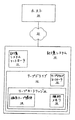
最初に図1を参照すると、テープドライブ12および磁気テープ媒体14を含む例示的な記憶システム10が記載される。当該記憶システム10はこの明細書中に記載される例示的なサーボ方法およびシステムを用い得る。テープ記憶システム10は記憶システムコントローラ11を含み得、当該記憶システムコントローラ11は、記憶システム10内に含まれる1つ以上のテープドライブ12を制御し、かつテープカートリッジ16を選択してテープドライブ12に挿入するのに用いられるテープピッカ(図示せず)などの記憶システム10の他の構成要素を制御する。当該記憶システム10は、ホスト/ストレージ接続22を介して記憶システム10にI/O要求を伝送するホストシステム20に結合され得る。
Referring initially to FIG. 1, an
テープドライブ12は主要な記憶媒体に対してデータの読取および書込を行なう。当該主要な記憶媒体は、取外し可能な磁気テープカートリッジ16内に含まれる磁気テープ媒体14として図1に示される。磁気テープ媒体14は、典型的には、データを記憶する磁気材料の薄膜を含む。当該テープ媒体14は間隔を空けて配置された1対のリールの間をテープドライブ12によって移動させられ、データトランスデューサを通り過ぎて情報を記録し得るかまたはリードバックし得る。データトランスデューサヘッドは典型的にはヘッドキャリッジアセンブリの一部であり、当該ヘッドキャリッジアセンブリは、テープドライブコントローラ13によってテープ経路に横方向に平行移動可能であり、かつ、トランスデューサヘッドをテープ経路に隣接して維持するよう位置決めシステムに応答可能である。これにより、テープドライブコントローラ13は、LTMを補償したりデータトラックを追従したりするために、たとえばサーボシステムからの位置情報に応答して、記憶媒体に対してトランスデューサヘッドを横方向に平行移動させ得る。当該技術において一般に公知であるように、読出/書込動作およびサーボ制御信号に応答してデータトランスデューサヘッドを支持しかつ平行移動させるのにさまざまなアクチュエータ装置が用いられてもよい。
The
ある種類のテープドライブシステムにおいては、リールの一方がテープドライブ12の一部であり、もう一方のリールが取外し可能なテープカートリッジ16の一部である。この種類のテープドライブシステムの場合、テープドライブ12の一部であるリールは一般に巻取りリールと称され、テープカートリッジ16の一部であるリールは一般にカートリッジリールと称される。テープカートリッジ16をテープドライブ12に挿入すると、カートリッジリール上の磁気テープ媒体14がテープドライブ12の巻取りリールに結合される。続いて、テープドライブ12からテープカートリッジ16を取外す前に記憶テープ14がカートリッジリールに再び巻かれて、巻取りリールから外される。テープカートリッジ16はさらに、当該技術において一般に公知である補助メモリ18を含み得る。
In one type of tape drive system, one of the reels is part of the
さまざまな例示的なテープドライブシステムおよび方法が、この明細書中に記載されるさまざまな例示的な位置およびサーボシステムおよび方法とともに用いられてもよく、たとえば米国特許第6,246,535号、第6,108,159号および第5,371,638号ならびに米国特許出願第09/865,215号に記載されるものを含み得るが、そのすべてはこれによりこの明細書中に完全に述べられるかのように引用により援用される。しかしながら、(ことによると当業者にとって明らかとなるいくつかの変形例を備えた)他のさまざまな好適なテープドライブシステムおよびサーボシステムが、記載される例示的なシステムおよび方法のうちの1つ以上とともに用いられ得ることを当業者は認
識するだろう。
Various exemplary tape drive systems and methods may be used with the various exemplary position and servo systems and methods described herein, eg, US Pat. No. 6,246,535, No. 6,108,159 and 5,371,638, as well as those described in US patent application Ser. No. 09 / 865,215, all of which are hereby fully described herein. Is incorporated by reference as follows. However, various other suitable tape drive systems and servo systems (possibly with several variations that will be apparent to those skilled in the art) are one or more of the exemplary systems and methods described. One skilled in the art will recognize that can be used with.
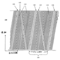
図2Aに示される例示的なサーボトラック100は、磁気記憶媒体に記録され得、媒体ドライブシステムに位置情報を供給し得る。特に、サーボトラック100が媒体ドライブのトランスデューサヘッドによって読取られると、サーボトラックおよび磁気記憶テープに対するトランスデューサヘッドの相対位置が検出され得る。ドライブサーボシステムは、位置情報に基づいて記憶媒体に対するトランスデューサヘッドの位置を調節し得る。
The
サーボトラック100は周期的な(すなわち繰返す)サーボフレーム101を含み、当該サーボフレーム101は長さ寸法Lfを有し、トーンフィールド110と、異なっているが識別可能な少なくとも2つの同期マーク120および122とを有する。トーンフィールド110は、第1のアジマス角に向けられるトーンフィールドまたは距離フィールドと称されるサーボマークと呼ばれる一定の間隔を有する磁束遷移を含む。加えて、少なくとも1つの同期マークたとえば同期マーク122は、長さLfの各サーボフレームの同期マーク122の前後におけるトーンフィールド110における磁束遷移の数がサーボトラック100内における横方向の位置によって異なるようにトーンフィールド110内において第2のアジマス角に埋込まれる。一例においては、トーンフィールド110の磁束遷移が公知の距離だけ間隔を空けて配置され、これにより、たとえば連続した同期マーク120と122との間のサーボトラック100の長さに沿った距離が直接測定される。この場合、同期マーク120は第1のアジマス角に向けられ、サーボフレーム101の始端または先頭に関連付けられ、同期マーク122はサーボフレーム101の中間点に関連付けられ(但し、以下に述べられるように必ずしもサーボフレーム101の物理的な中心には位置せず)、この場合、次の同期マーク120は現在のサーボフレーム101の終端と新しいサーボフレーム101の先頭とを示す。この態様では、各サーボフレーム101はその先頭および終端が、第1のアジマス角に向けられた同期マーク120と境を接し、その間には、第1のアジマス角に向けられた一定の間隔を有する一定数の磁束遷移のトーンフィールドがあり、ここには、第2のアジマス角に向けられた異なる同期マーク122が埋込まれている。
サーボトラック100を検出するのに用いられる読取トランスデューサは、その幅がサーボトラック幅に比べて狭くてもよく、このようなトランスデューサは、サーボトラックの磁束遷移を検出すると、サーボトラック100内における当該サーボトラック100の長さに沿った細い線を追跡する。サーボトラック100内における当該サーボトラック100の中心線に対して平行な線に沿って、トーンフィールド110における磁束遷移の数は各サーボフレーム101の中間フレーム同期マーク122の前後で異なるだろう。たとえば、サーボトラック100の下半分を通りこの線に沿って左から右に移動させると、同期マーク122の後よりも同期マーク122の前の方がサーボフレーム101のトーンフィールド110における磁束遷移の発生する数が多くなる。逆に、サーボトラック100の上半分付近では、同期マーク122の前よりも同期マーク122の後の方がトーンフィールド110における磁束遷移の発生する数が多くなる。先頭フレーム同期マーク120から中間フレーム同期マーク122までのサーボフレーム101内のトーンフィールド110における磁束遷移の数を数え、中間フレーム同期マーク122から次の先頭フレーム同期マーク120までの同じサーボフレーム内のトーンフィールド110における磁束遷移の数を数え、さらにこれらの数を引くことにより、サーボトラック100に対する読取ヘッドの横方向の相対位置を導き出すことができる。
The read transducer used to detect the
この例においては、同期マーク120および122は、トーンフィールド110のサーボマークに類似しているがサイズが異なるさまざまな識別可能なマークとアジマス角が異なる同期マーク122とを形成する磁束遷移として示される。他の例においては、同期マーク120および122のうち1つ以上は、中間フレーム同期マーク122の前後におけ
るトーンフィールドサーボマークの数が横方向の位置によって異なるようにサーボフレームの境界を画定しかつ中間フレーム同期マークを形成するよう読取ヘッドによって識別可能な他の特徴を含み得る。このような同期マーク120および122は同期マークの検出を向上させるようフォーマットされることにより、雑音、信号歪みおよび他の検出チャネル特徴から生じる不確実性を最小限にしつつ長手方向の位置測定の分解能を向上させ得る。
In this example, sync marks 120 and 122 are shown as magnetic flux transitions that form various identifiable marks that are similar to the servo marks of
一例においては、サーボトラック100は磁気記憶テープの長さに沿って横方向に予め記録され、特定の媒体ドライブのための読取トランスデューサ幅およびデータトラック幅に比べて幅が広い。したがって、サーボトラック100は、その幅にわたる複数のデータトラックインデックス位置をサーボ制御システムに与え得る。図2Bは、サーボトラック100に沿ったドライブシステムの比較的狭い読取トランスデューサの例示的な経路と、読取ヘッド(下記のサーボトラック100)において生成される結果として生じた読取信号とを示す。トーンフィールド110は生成された読取信号の長手方向のテープ速度に比例するトーン周波数を信号に与え、ここには、トーン信号周波数とは異なりかつ互いに異なる別個の周波数を有する2つの固有の同期マーク120および122が埋込まれている。上述のとおり、サーボトラック100は、サーボトラック100の長さに沿った距離において同期マーク120および122が周期的に発生するように構成される。連続した先頭フレームマーク120の間における分離距離が1つのサーボフレーム間隔Lfの長さを規定し、中間フレーム同期マーク122は、中間フレーム同期マーク122の前後のサーボフレームにおけるトーンフィールド110の磁束遷移の数が横方向の位置によって異なるように先頭フレーム同期マーク120の間に位置決めされる。この例においては、第1および第2の同期マーク120および122は固有の磁束間隔を有し、これらはともにトーンフィールドの磁束間隔よりも大きい。
In one example, the
たとえば好適な信号デコーダなどを含む好適なコントローラは、その固有の磁束間隔によって先頭フレーム同期マーク120を識別し、その固有の磁束間隔122によって中間フレーム同期マークを識別する。当該コントローラはさらに、同期マーク120と122との間における間隔を、その間にあるトーンフィールド110における磁束遷移の数を数えることによって決定する。
A suitable controller, including a suitable signal decoder, for example, identifies the first
この例においては、サーボ読取ヘッドはサーボトラック100に沿って移動し、図示のとおり連続したパルスのシーケンスを生成する。ピーク検出チャネルはサーボヘッドからの読取信号を処理し得る。加えて、読取ヘッド信号はアナログのフロントエンド(AFE)チップによって受信され得、好適なアナログ−デジタルコンバータおよび検出チャネルによって数値データに変換され得る。次いで、デジタルパルスまたは数値データは、パルス間の間隔を検出し、かつ同期マーク120および122ならびにトーンフィールド110に関連付けられたそれらのパルスを識別するよう構成された同期マーク検出ロジックによって処理され得る。代替的には、デジタルパルスまたは数値データは相関検出器または最大尤度検出器によって処理されて、同期マーク120および122ならびにトーンフィールド110を識別し得る。たとえばアナログまたはデジタルの読取信号を処理してサーボトラック100の特徴を識別する他のさまざまな方法が当業者に明らかとなるだろう。
In this example, the servo read head moves along
一例においては、1ミクロンの間隔がトーンフィールドパルスを識別し、より長い間隔が同期マーク120および122を識別し、たとえば、2.0ミクロンの間隔が中間フレーム同期マーク122を識別し、1.5ミクロンの間隔が先頭フレーム同期マークを識別する。したがって、当該コントローラは、トーンフィールド110に関連付けられる検出されたピークの比較的小さな間隔とは異なる同期マーク信号における検出されたピークの比較的大きな間隔に基づいて、同期マーク120および122を識別する。
In one example, a 1 micron interval identifies a tone field pulse, a longer interval identifies sync marks 120 and 122, for example, a 2.0 micron interval identifies an intermediate
サーボトラック100は、図示のとおり、読取ヘッド経路に沿ってたとえば2ミクロンの幅を有する狭いサーボ読取要素(図示せず)によって読取られる。サーボトラックの幅はいくつかのデータトラック幅にわたっており、データトラックを読取りかつ記録するための複数のインデックス位置を提供し得る。一例においては、サーボトラック100の横方向の幅が94ミクロンであり、書込まれた各々のデータトラック幅が10ミクロンであるので、8個のデータトラックインデックス位置がサーボトラック100の幅内に設けられる。
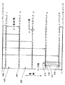
図3を参照すると、たとえばドライブシステムに関連付けられるハードウェア、ソフトウェアおよびファームウェアのいずれかの組合せによって実行され得る例示的なサーボ位置計算が詳細に説明される。トーンフィールド110からの信号、ならびに同期マーク120および122に関連付けられる信号が識別されると、サーボトラック100内におけるサーボ読取ヘッドの位置が決定され得る。先頭フレーム同期マーク120から中間フレーム同期マーク122までの距離、および中間フレーム同期マーク122から次のサーボフレームの先頭フレーム同期マーク120までの距離は、サーボトラック100内におけるサーボ読取ヘッドの横方向の位置によって異なる。サーボ読取ヘッドがサーボトラックを下方に移動すると、先頭フレーム同期マーク120と中間フレーム同期マーク122との間の距離が増え、逆に、中間フレーム同期マーク122と次のサーボフレームの先頭フレーム同期マーク120との間の距離が減る。これらの2つの距離はトーンフィールド110を距離基準として用いることによって測定され、当該2つの距離は、サーボトラック100に対するサーボ読取ヘッドの横方向の位置を計算するための情報を提供する。
Referring to FIG. 3, an exemplary servo position calculation that may be performed, for example, by any combination of hardware, software, and firmware associated with a drive system is described in detail. Once the signal from
この例においては、サーボ読取ヘッドがサーボトラック100の中心、すなわち「サーボトラックCL」に横方向に位置決めされると、先頭フレーム同期マーク120から中間フレーム同期マーク122までと中間フレーム同期マーク122から次の先頭フレーム同期マーク121までとの距離が等しくなり、トーンフィールド110の磁束遷移(または読取信号におけるカウントパルス)の数が等しくなる。一例においては、位置信号の値はサーボトラックの中心CLのために0に設定されてもよい。
In this example, when the servo read head is positioned laterally at the center of the
サーボトラックの中心線より上方のサーボヘッドの位置については、先頭フレーム同期マーク120から中間フレーム同期マーク122までのカウントパルスN1の方が中間フレーム同期マーク122から次の先頭フレーム同期マーク120までのN2よりも数が少ない。サーボヘッドのこれらの位置については、ヘッド位置を計算すると値はマイナスになるだろう。計算されたヘッド位置は、当該ヘッド位置がサーボトラック100の上方のエッジの方に移動すると0から直線的に低減する。
Regarding the position of the servo head above the center line of the servo track, the count pulse N1 from the first
サーボトラックの中心線より下方のサーボヘッドの位置については、先頭フレーム同期マーク120から中間フレーム同期マーク122までのカウントパルスN1の方が中間フレーム同期マーク122から次の先頭フレーム同期マーク120までのN2よりも数が多い。サーボヘッドのこれらの位置については、ヘッド位置を計算すると値はプラスになるだろう。計算されたヘッド位置は、当該ヘッド位置がサーボトラック100の下方のエッジの方に移動すると0から直線的に増大する。他の例示的な計算では、0の基準点はサーボトラック100の上部または下部のエッジを含み得る。
As for the position of the servo head below the center line of the servo track, the count pulse N1 from the first
サーボフレーム101内における読取ヘッドによって検出される中間フレーム同期マーク122の位置は、サーボヘッドがサーボトラック100を上方に移動するとサーボフレーム101の始端の方に進み、中間フレーム同期マーク122は、サーボヘッドがサーボトラック100を下方に移動するとサーボフレーム101の始端から遠ざかる。この説明が読取ヘッド、サーボトラックなどの基準のフレームおよび相対運動に部分的に依存することを当業者は認識するだろう。
The position of the intermediate
サーボトラック100の中心線からのヘッドの横方向の距離Pと、先頭フレーム同期マーク120から中間フレーム同期マーク122までのX1および中間フレーム同期マーク122から次の先頭フレーム同期マーク120までのX2の間の距離との関係が式1に示され、ここでは、横軸に対する2つのマークのアジマス角はThetaである。
Between the horizontal distance P of the head from the center line of the
P=[1/(4*tan(Theta))]*(X1−X2) 式1
寸法X1およびX2は以下の式および方法を用いることによって測定される。一例においては、トーンフィールドパルス間における間隔の長さは1ミクロンである。先頭フレーム同期マーク120から中間フレーム同期マーク122までのトーンフィールドパルスの数、N1が数えられ、中間フレーム同期マーク122から次のサーボフレーム120の先頭フレーム同期マーク120までのトーンフィールドにおけるパルスの数、N2が数えられる。この例においては、先頭フレーム同期マーク120からトーンフィールドまでの距離は1.5ミクロンであり、中間フレーム同期マーク122からトーンフィールドまでの距離は2.0ミクロンである。X1およびX2はこれらのパラメータから計算され、式1がPについて以下のように解かれる。
P = [1 / (4 * tan (Theta))] * (X1-X2)
Dimensions X1 and X2 are measured by using the following equations and methods. In one example, the length of the interval between tone field pulses is 1 micron. The number of tone field pulses from the first
X1=(N1+2.5)ミクロン 式2
X2=(N2+2.5)ミクロン 式3
P=(1/[4*tan(Theta)])*(N1−N2)ミクロン 式4
一例においては、トーン間隔の長さは1ミクロンではないが、トーン間隔の一定数Nがサーボフレームの長さLfに等しくなるようなものである。この例においては、先頭フレームマーク120からトーンフィールドまでの距離はXsfであり、中間フレームマーク122からトーンフィールドまでの距離はXmfである。この場合、寸法X1およびX2は、先頭フレームマーク120から中間フレームマーク122までのトーンフィールドパルスの数N1を数え、中間フレームマーク122から次のサーボフレームの先頭フレームマークまでのトーンフィールドパルスの数N2を数えることによって測定される。X1およびX2はこれらのパラメータから計算され、式1がPについて以下のように解かれる。
X1 = (N1 + 2.5) microns
X2 = (N2 + 2.5) microns
P = (1 / [4 * tan (Theta)]) * (N1-N2)
In one example, the length of the tone spacing is not 1 micron, but a constant number N of tone spacings is equal to the servo frame length Lf. In this example, the distance from the
X1=Lf/N*(N1−1)+Xsf+Xmf 式5
X2=Lf/N*(N2−1)+Xsf+Xmf 式6
P=(Lf/[N*4*tan(Theta)])*(N1−N2) 式7
一例においては、X1およびX2は、トーンフィールドと同期マークとの間の寸法間隔を、トーン間隔の積分プラス分数部によって表わされる値に計算することによって高い分解能で測定される。トーン間隔の分数部は、0から最大値Gの間で変動し得る数によって表わされる。トーン間隔の長さは、トーン間隔の一定数Nがサーボフレームの長さLfに等しくなるような長さである。トーン磁束間隔の1/G倍の寸法単位で表わすと、全トーン間隔の長さはGに等しく、サーボフレームの長さはN*Gである。式1でX1およびX2の値を計算するために、アキュムレータを用いて、先頭フレームマーク120で始まり中間フレームマーク122で終わる寸法間隔と、同様に中間フレームマーク122で始まり次のサーボフレームの先頭フレームマーク120で終わる寸法間隔とを加える。Gの値は、トーンパルスが検出されるとアキュムレータに加えられる。同期マークが検出されると、トーンフィールドと同期マークとの間の、Gよりも大きな数である間隔がアキュムレータに加えられる。先頭フレームマークの磁束遷移間隔がトーンフィールドの磁束遷移間隔の1.5倍であれば、先頭フレームマークのためにアキュムレータに加えられる値は1.5*Gである。トーンフィールドと中間フレームマークとの間の間隔はサーボ読取ヘッドの横方向の位置によって異なり、中間フレームマーク122の磁束間隔によって、およびトーンフィールド110の磁束間隔と中間フレームマーク122の磁束間隔との和によって制限される。中間フレームマーク122が検出されると、トーンフィールドと中間フレーム122のマークとの間の距離が計算され、これはトーンフィールド間隔の積分プラ
ス分数部における距離を表わすGよりも大きな数となる。中間フレームマークの磁束間隔がトーン磁束間隔の2倍であれば、トーンフィールド110と中間フレームマーク122との間の間隔の値は2*Gから3*Gの間に制限され、この値がアキュムレータに加えられる。アキュムレータによって計算される直線寸法の分解能はLf/N*Gであり、先頭フレームマーク120から中間フレームマーク122までの寸法を合計するアキュムレータの値はN1であり、中間フレームマークから次のサーボフレームの先頭フレームマークまでの寸法を合計するアキュムレータの値はN2である。X1およびX2はこの態様で測定され、式1がPについて以下のように解かれる。
X1 = Lf / N * (N1-1) + Xsf +
X2 = Lf / N * (N2-1) + Xsf + Xmf Equation 6
P = (Lf / [
In one example, X1 and X2 are measured with high resolution by calculating the dimensional spacing between the tone field and the sync mark to the value represented by the integral plus fractional part of the tone spacing. The fractional part of the tone spacing is represented by a number that can vary between 0 and the maximum value G. The length of the tone interval is such that a constant N of tone intervals is equal to the servo frame length Lf. Expressed in
X1=(Lf/N*G)*N1 式8
X2=(Lf/N*G)*N2 式9
P=(Lf/[N*G*4*tan(Theta)])*(N1−N2) 式10
一例においては、X1およびX2は、トーンフィールドパルスに位相ロックされる高周波パルス発生器を用いることによって高い分解能で測定される。パルス発生器はトーンフィールドによって生成されたパルスの数を乗算し、一般に位相ロック発振器またはPLOと称される。当該PLOは、トーンフィールドの各パルスのために一定数のパルスGを生成し、概してトーンフィールドよりも微細な位置分解能でこれらのパルスをカウンタに供給する。PLOはまた、同期マーク領域を通じて連続的に数えるためのパルスを供給する。サーボフレーム同期マーク間の距離は、同期マーク間におけるPLOパルスを数えることによってより微細な分解能で、先頭フレーム同期マーク120からトーンフィールドまでの距離(この例では1.5ミクロン)と中間フレーム同期マーク122からトーンフィールドまでの距離(この例では2.0ミクロン)とを加えずにより正確に測定され得る。
X1 = (Lf / N * G) * N1 Formula 8
X2 = (Lf / N * G) * N2 Equation 9
P = (Lf / [N * G * 4 * tan (Theta)]) * (N1-N2)
In one example, X1 and X2 are measured with high resolution by using a high frequency pulse generator that is phase-locked to the tone field pulse. The pulse generator multiplies the number of pulses generated by the tone field and is commonly referred to as a phase locked oscillator or PLO. The PLO generates a fixed number of pulses G for each pulse in the tone field, and supplies these pulses to the counter with a finer position resolution than the tone field. The PLO also provides pulses for continuous counting through the sync mark area. The distance between the servo frame synchronization marks is a finer resolution by counting the PLO pulses between the synchronization marks. The distance from the head
一例においては、寸法X1およびX2は以下の式および方法を用いることによってPLOで測定される。サーボフレームの長さLfは公知であり、トーンフィールドパルス間における間隔の長さ、Xtoneもまた公知であり、たとえば1ミクロンである。連続した先頭フレーム同期マーク120間におけるトーンパルス間隔の総数Nは一定であり、Lf/Xtoneに等しい。サーボフレームにおけるPLOパルスの総数は定数、すなわちN*Gであり、各PLOパルスによって表わされる長さ間隔はLf/(N*G)である。先頭フレーム同期マーク120から中間フレーム同期マーク122までのPLOパルスの数N1が数えられ、中間フレーム同期マーク122から次のサーボフレームの先頭フレーム同期マーク120までのPLOパルスの数N2が数えられる。
In one example, dimensions X1 and X2 are measured with PLO by using the following equations and methods. The length Lf of the servo frame is known, and the distance between the tone field pulses, Xtone, is also known, for example 1 micron. The total number N of tone pulse intervals between consecutive first frame synchronization marks 120 is constant and equal to Lf / Xtone. The total number of PLO pulses in the servo frame is a constant, ie N * G, and the length interval represented by each PLO pulse is Lf / (N * G). The number N1 of PLO pulses from the first
値N1は、先頭フレーム同期マーク120と中間フレーム同期マーク122との間のPLOパルス間隔における距離を表わす。値N2は、中間フレーム同期マーク122と次のサーボフレーム120の先頭フレーム同期マーク120との間のPLOパルス間隔における距離を表わす。X1およびX2はこれらのパラメータから計算され、式1がPについて以下のように解かれる。
The value N1 represents the distance in the PLO pulse interval between the first
X1=(Lf/[N*G])*N1 式11
X2=(Lf/[N*G])*N2 式12
式11および12からの値を式1に代入すると以下のとおりである。
X1 = (Lf / [N * G]) * N1 Formula 11
X2 = (Lf / [N * G]) *
Substituting the values from
P=(Lf/[4*N*G*tan(Theta)])*(N1−N2) 式13
サーボトラックにおけるサーボヘッドの横方向の位置に対する上述の解は距離の測定値およびジオメトリの一般原理から生じる。変数は、値N1およびN2によって表わされる測定された距離である。サーボヘッドの位置はN1からN2を引き、定数で乗算することによって解かれる。パラメータLf、N、ThetaおよびGは、サーボトラックのジオメトリおよびPLOの増倍率によって決定される定数である。したがって、横方向のサーボヘッド位置に対する解は、テープ速度および他の時間依存性パラメータなどの変数とは
無関係である。横方向の位置が計算される分解能は、Lf、N、G、Theta、および、テープの長手方向軸に沿ったトーン磁束変化間隔の長さに対する値を選択することによって決定される。当該分解能は、複数のサーボフレームにわたるN1およびN2の測定値を累積することによってさらに改善され得る。
P = (Lf / [4 * N * G * tan (Theta)]) * (N1-N2)
The above solution for the lateral position of the servo head in the servo track results from the general principles of distance measurements and geometry. The variable is the measured distance represented by the values N1 and N2. The position of the servo head is solved by subtracting N2 from N1 and multiplying by a constant. The parameters Lf, N, Theta and G are constants determined by the servo track geometry and the PLO multiplication factor. Thus, the solution for lateral servo head position is independent of variables such as tape speed and other time dependent parameters. The resolution with which the lateral position is calculated is determined by selecting values for Lf, N, G, Theta, and the length of the tone flux change interval along the longitudinal axis of the tape. The resolution can be further improved by accumulating N1 and N2 measurements across multiple servo frames.
一例においては、PLOは、完全なサーボフレームLfの全体にわたって位相ロックをトーンフィールド110の平均的な位相に維持する。PLOの動的な応答は、位相ロックを失わずに、通常の運動によって引起こされる位相変動を追跡しつつ位相エラー信号における高周波数変動を可能にするよう制限される。先頭フレーム同期マーク120と中間フレーム同期マーク122との磁束遷移間隔が、これらのマークにわたるトーンフィールド間隔の整数を与えるよう選択されることにより、PLOが妨害されずに当該マークを遷移させることが可能となる。代替的には、PLOの位相エラーは、トーンフィールドが検出され同期マーク検出中に一定に保持されている間隔中にサンプリングされ得る。
In one example, the PLO maintains phase lock at the average phase of the
加えて、1つの例示的な方法は、読取信号が検出チャネルに存在しない場合、ギャップまたは間隔なしに連続的な読取信号を供給することによりトラック追従位置信号を得る際の振幅感度を減らすかまたは取除く。サーボトラックが、サーボ読取ヘッドによって検出される磁束遷移を連続的に供給するので、連続的な読取信号が検出に利用可能となって連続的なパルスシーケンスが生成される。連続的な読取信号により信号処理が向上して、極めて信頼性の高い信号増幅調整がもたらされる。システムによって検出されかつ処理されなければならないパルスデータストリームにはギャップがなく、これにより、データストリームにギャップが存在する時間間隔中に検出チャネルが雑音源によって影響を受けやすくなる。たとえば、好適なトーンフィールドは、帯域幅が最小限であるかまたは狭い検出チャネルを維持するための方法を提供する。こうして、当該トーンフィールドは、チャネル帯域幅を最小限にしかつ帯域外の雑音除去を最大限にすることにより雑音を減らす。加えて、トーンフィールドは、自動的な利得制御システムを制御するための、振幅ピークが高い検出チャネル信号を供給し得る。さらに、位置分解能は、サーボトラックにおけるトーンフィールドパルスに位相ロックされた発振器のパルス増倍率、または他の長さ補間方法によって向上し得る。 In addition, one exemplary method reduces amplitude sensitivity in obtaining a track following position signal by providing a continuous read signal without gaps or spacings when the read signal is not present in the detection channel, or Remove. Since the servo track continuously supplies magnetic flux transitions detected by the servo read head, a continuous read signal is available for detection and a continuous pulse sequence is generated. The continuous read signal improves signal processing and provides a very reliable signal amplification adjustment. There are no gaps in the pulsed data stream that must be detected and processed by the system, which makes the detection channel susceptible to noise sources during time intervals when there are gaps in the data stream. For example, a suitable tone field provides a method for maintaining a detection channel with minimal or narrow bandwidth. Thus, the tone field reduces noise by minimizing channel bandwidth and maximizing out-of-band noise rejection. In addition, the tone field may provide a detection channel signal with a high amplitude peak to control an automatic gain control system. Further, the position resolution may be improved by an oscillator pulse multiplication phase locked to the tone field pulses in the servo track, or other length interpolation methods.
例示的な方法およびシステムのさまざまな局面の実現例は、当業者によって認識されるように単純なパルス検出および論理回路を用い得、記憶システムまたは媒体ドライブシステムに関連付けられるソフトウェア、ファームウェアおよびハードウェアのうちの1つ以上において具体化され得る。 Implementations of the various aspects of the exemplary method and system may use simple pulse detection and logic circuitry, as will be appreciated by those skilled in the art, and include software, firmware and hardware associated with the storage system or media drive system. It may be embodied in one or more of them.
別の局面においては、サーボトラックを書込むための例示的な方法およびシステムが提供される。一例においては、サーボトラックは、サーボトラックを同時に記録する1対のフォーマット記録ヘッドによって書込まれる。2つのヘッドが長手方向に位置決めされるが、一方のヘッドはテープの長手方向の長さに沿って他方のヘッドの前方にある。第1の書込ヘッドは、そこに埋込まれた同期マーク(たとえば先頭フレーム同期マーク120)を有する連続したサーボトラックトーンフィールド(たとえば図2Bのトーンフィールド110を参照)を記録し、当該第1のヘッドを追跡する第2のヘッドは、第1のヘッドの連続したサーボトラックの部分に周期的に上書きし、したがってこれを置換えて、トーンフィールドおよび/または第1の同期マークに対して異なるアジマス角で第2の同期マーク(たとえば中間フレーム同期マーク122)を作成する。たとえば、第2のフォーマットヘッドは、第1のヘッドによって書込まれた第1の同期マーク間におけるサーボトラックに固有の第2の同期マークを書込む。当該第2のヘッドによって書込まれた同期マークは、トーンフィールドにおけるサーボマークの磁束間隔および/またはアジマス角とは異なり、かつ第1のヘッドによって書込まれた同期マークの磁束間隔および/またはアジマス角とも異なる磁束間隔および/またはアジマス角を有する。2つの記録ヘッドは、第1
のヘッドによって書込まれた領域と第2のヘッドによって書込まれた他の領域とで連続した複合サーボトラックを作成し得る。この態様では、サーボトラックは、2つ以上のアジマス角に向けられた磁束遷移を有する領域からなり、当該領域では、複数のアジマス角での遷移がサーボトラックの同じ長手方向および横方向の寸法を占めている。2つ以上のアジマス角で記録される磁束遷移はテープの長手方向軸および横軸に沿って連続して発生しないが、これらの軸によって規定される単一の領域または区域においては同時に発生する。他の例においては、以下に記載されるように、同期マークのうちの1つ(または両方)はサーボトラックの消去された領域または帯域を含み得る。
In another aspect, an exemplary method and system for writing servo tracks is provided. In one example, the servo track is written by a pair of format recording heads that simultaneously record the servo track. Two heads are positioned longitudinally, with one head in front of the other head along the longitudinal length of the tape. The first write head records a continuous servo track tone field (see, for example,
A continuous servo track can be created with the area written by one head and the other area written by the second head. In this aspect, the servo track consists of a region having magnetic flux transitions directed to more than one azimuth angle, where transitions at multiple azimuth angles cause the same longitudinal and lateral dimensions of the servo track. is occupying. Magnetic flux transitions recorded at two or more azimuth angles do not occur continuously along the longitudinal and transverse axes of the tape, but occur simultaneously in a single region or area defined by these axes. In other examples, as described below, one (or both) of the synchronization marks may include erased regions or bands of servo tracks.
一例においては、第1のヘッドはテープの長手方向軸に対する垂線からたとえば9°のアジマス角に向けられた磁気ギャップを有する。アジマス角はたとえば0°〜20°の範囲であり得る。第2のヘッドは、第1のヘッドとは異なるアジマス角、たとえば第1のヘッドの角度に等しいがこれとは逆のアジマス角に向けられた磁気ギャップを有する。したがって、2つのヘッドは、大きさが等しいがテープの横軸とは逆のサインまたは向きのアジマス角に向けられた磁束遷移を書込む。他の例においては、第1および第2の書込ヘッドのために(0を含む)さまざまなアジマス角を用いて、トーンフィールド、先頭フレーム同期マークおよび/または中間フレーム同期マークを記録し得る。 In one example, the first head has a magnetic gap that is oriented, for example, at an azimuth angle of 9 ° from a normal to the longitudinal axis of the tape. The azimuth angle can range, for example, from 0 ° to 20 °. The second head has a magnetic gap that is directed to a different azimuth angle than the first head, eg, an azimuth angle equal to but opposite to the first head angle. Thus, the two heads write magnetic flux transitions directed at an azimuth angle of equal magnitude but opposite to the tape's horizontal axis. In other examples, different azimuth angles (including zero) may be used for the first and second write heads to record the tone field, the first frame sync mark, and / or the intermediate frame sync mark.
一例においては、記載される例示的なサーボトラックおよび位置検出方法から得られる位置信号がトラック追従システムに適用されて、サーボトラックの側に沿った、隣接する対のサーボトラック間における、または複数のサーボトラックによって分離される領域に分散されたデータ帯域に長手方向に記録された複数のデータトラックの書込および読取が行なわれる。データトラック追従に有用な位置エラー信号を得るために、記載のとおりに位置計算から得られるデジタル位置信号が所望のデータトラック位置に対する基準位置から減じられる。したがって、各サーボトラックの幅は複数のデータトラック幅にわたっており、データ帯域のデータトラックに関連付けられる複数のインデックスおよび基準位置を含む。 In one example, a position signal obtained from the exemplary servo track and position detection method described is applied to a track following system so that along the servo track side, between adjacent pairs of servo tracks, or multiple A plurality of data tracks recorded in the longitudinal direction are written and read in a data band distributed in a region separated by servo tracks. To obtain a position error signal useful for data track tracking, the digital position signal obtained from the position calculation as described is subtracted from the reference position for the desired data track position. Thus, the width of each servo track spans multiple data track widths and includes multiple indexes and reference positions associated with data tracks in the data band.
図4は、一例に従った記憶テープに横方向に記録された複数のサーボトラックを示す。サーボトラック400は、サーボトラック400によって分離されるデータ帯域405に対する複数の領域を形成するよう横方向に間隔が空けられる。また、隣接するサーボトラック400の組の間におけるデータトラックを記録しかつ読取るよう構成され、データヘッドクラスタ417におけるデータ書込および読取要素の組を含む例示的なデータ記録ヘッド416が示される。データヘッドクラスタ417は、クラスタの最も外側の位置に横方向に配置され、サーボトラック400にわたって構成される専用のサーボ読取要素418および419を含み得る。サーボ読取要素418および419は、データがデータ帯域405との間でやり取りされている間、2つの隣接するサーボトラック400から同時に位置情報を読取りかつ供給し得る。他の例においては、データヘッド416は横方向にずらされた単一の専用のサーボ読取要素418を含み得るか、または断続的に平行移動してデータヘッドクラスタ417における読取要素で隣接するサーボトラック400を読取り、データ帯域405内のデータトラックに戻って読取または書込を続け得る。
FIG. 4 shows a plurality of servo tracks recorded laterally on a storage tape according to an example. Servo tracks 400 are laterally spaced to form a plurality of regions for
サーボ要素417および418に対応するヘッド416からの信号が前述の信号デコーダおよび検出器ロジックによって受信されて位置情報が決定され得る。ヘッド416はさらにヘッドアセンブリおよびアクチュエータに結合されてもよく、当該ヘッドアセンブリおよびアクチュエータが位置情報に応答して、サーボトラック400および磁気記録媒体に対する所望の横方向の位置にヘッド416を平行移動させる。
Signals from
この例においては、従来の方法と比べてトラック追従位置不良(TMR)エラーが比較的小さい可能性がある。というのも、サーボ位置ヘッドがデータヘッド要素クラスタ内に
含まれ得るからである。こうして、TMRエラーが、ヘッドおよび記憶テープのリソグラフィの許容差および熱膨張特性にまで減じられ得る。
In this example, there is a possibility that the track following position error (TMR) error is relatively small as compared with the conventional method. This is because the servo position head can be included in the data head element cluster. Thus, TMR errors can be reduced to lithographic tolerances and thermal expansion characteristics of the head and storage tape.
図4の例示的なサーボトラックフォーマットは、テープの横方向の寸法にわたる4つのデータ帯域405と境を接する5つのサーボトラック400を含む。この例においては、サーボトラック405は幅が94μmであり、データ帯域405は幅が2700μmである。サーボトラックフォーマット、位置および寸法は単に例示的なものであり、さまざまな記憶システムおよび所望のカートリッジデータ容量に対処するために任意の寸法、数および構成のサーボトラック400およびデータ帯域405が企図される。
The exemplary servo track format of FIG. 4 includes five
一例においては、サーボトラック400は各サーボトラックに専用の書込カレントドライバで個々に書込まれ、これにより、各サーボトラックに対して固有の情報をそのトラックに対する長手方向のデータフィールドに符号化することが可能となる。このような固有の情報の例には、サーボトラック識別数、サーボトラック較正情報などが含まれる。図5は、図4に図示される複数のサーボトラック400を書込み得るフォーマットヘッド500の構成に対する概念図を示す。一例においては、複数の書込要素503を有する第1の書込ヘッドクラスタ502は、埋込まれた先頭フレーム同期マークがサーボフレーム間隔Lfの間隔を空けられた状態で、一定の周波数トーンで同時に複数のサーボトラック(たとえば5個のサーボトラック)を書込む。磁束遷移はテープの横軸に対する第1のアジマス角で記録される。複数の書込要素505を有する第2の書込ヘッドクラスタ504は、第1のヘッドクラスタ502によって書込まれたトラックを周期的に上書きし、中間フレーム同期マークを作成する。書込要素505は第1の書込ヘッド要素503とは異なる第2のアジマス角で磁束遷移を作成するジオメトリを有する。書込要素505は、書込要素503によって書込まれたトーンおよび先頭フレーム同期マークに対して中間フレーム同期マークを正確に配置する目的で、書込要素503によって書込まれた磁束遷移を検出するために読取トランスデューサ506を含み得る。サーボトラックでテープをフォーマットするために任意の数の第1の書込ヘッド要素503および第2の書込ヘッド要素505が各々のうち1つを含めて企図されることに留意されたい。
In one example, servo tracks 400 are individually written to each servo track with a dedicated write current driver, which encodes information specific to each servo track into a longitudinal data field for that track. It becomes possible. Examples of such unique information include the number of servo track identifications, servo track calibration information, and the like. FIG. 5 shows a conceptual diagram of the configuration of the
中間フレーム同期マークがクラスタ504の第2の書込ヘッドによって書込まれるサーボフレームの位置は、第1の書込ヘッドクラスタ502によって書込まれたトーンおよび先頭フレーム同期マークに対して中間フレーム同期マークを正確に配置するよう制御される。各サーボトラックのサーボフレームに中間フレーム同期マークを正確に配置する例示的な一方法では、書込要素505の各々に直接隣接した読取トランスデューサ506が用いられる。書込ヘッドクラスタ504は読取トランスデューサ506を含む読取ヘッドクラスタに結合され得るか、または代替的には、書込要素505は、当該書込要素505を備えた共有の磁束シールド上に同時に作成される読取トランスデューサ506を含み得る。一例においては、読取トランスデューサ506のための位置は書込要素505に近接して、書込要素503と505との間に位置決めされる。
The position of the servo frame in which the intermediate frame synchronization mark is written by the second write head of
同時に共有シールド上に作成される書込および読取トランスデューサの構成は記録ヘッド作成方法においては一般的である。この構成では、トランスデューサ506は、それらが書込要素505に到達すると、第1の書込要素503によって書込まれたトーンフィールドおよび先頭フレーム同期マークを読取る。各サーボトラックに対する読取信号は好適な検出チャネルによって検出され、書込要素505の各々に別個の制御信号を供給して、サーボフレームにおいてそれらのサーボフレームのトーンおよび先頭フレーム同期マークに対して中間フレーム同期マークを正確に配置する。この態様では、書込要素503によって書込まれたトーンおよび先頭フレーム同期マークのパターンを備えた各サーボトラックは書込要素505の各々で別個に読取られて、別個のサーボトラックのサーボフレームに中間フレーム同期マークを正確に独立して配置する。
The configuration of the write and read transducers created on the shared shield at the same time is common in the recording head creation method. In this configuration, the
読取トランスデューサ506からの信号が好適な検出チャネルにおいて検出されると、先頭フレームマークおよびトーンパルスが検出され得る。先頭フレームマークが検出されると、いくつかのトーンパルスが、中間フレームマークが書込まれたサーボフレームの位置まで数えられ得る。特定の数のトーンパルスが数えられると、書込要素505はその位置で中間フレームマークを書込むよう励磁され得る。代替的には、トーンフィールドに固定されている位相ロック発振器PLOのパルスは、先頭フレームマークが検出されて中間フレームマークを書込むための位置が制御された後に数えられてもよい。PLOは、各トーンパルスのために複数のPLOパルスを供給し、かつ多くのトーンパルスの検出の平均に応じた位置カウント信号を供給することによって、中間フレームマークをサーボフレームに位置決めするための精度を高め得る。
When the signal from the read
書込要素503および505のクラスタは、従来のヘッド製作技術を用いて単一のウェハ上で製作され得る。単一のウェハ製作技術により精度および位置合わせが向上し得るが、これにより複数のサーボトラックが記憶テープに書込まれる。書込要素503および505は、これにより、製作中に長手方向および横方向の両方に位置合わせされる。
The cluster of
プログラム可能なパターン発生器およびパルス発生器を用いて、選択的な書込要素503および505に断続的な励磁をもたらすことにより1つ以上の所望のサーボトラックが記録され得る。例示的なパターンが好適なプログラマブルメモリに記録され得、所望のパルスを生成するのに用いられ得る。加えて、当該技術において周知のとおり、好適なカウンタと関連する論理との集合によってパターンが生成され得る。
Using a programmable pattern generator and pulse generator, one or more desired servo tracks can be recorded by providing intermittent excitation to
こうして、サーボトラックが、当該サーボトラックの適切なフォーマットを確実にするために検証ステーションで読取られ得る。書込要素503および505の2つのクラスタの後に位置決めされた複数のチャネル読取ヘッドが、書込まれたサーボトラックを読取る。読取信号は、サーボトラック検査のために好適な検出チャネルで検出される。各サーボトラックのために読取トランスデューサおよび検出チャネルが設けられる。この態様では、サーボトラックのための適切なフォーマットが確実にされる。
Thus, the servo track can be read at the verification station to ensure proper formatting of the servo track. A plurality of channel read heads positioned after two clusters of
別の局面に従うと、記録ヘッドに対する記憶テープの速度が例示的なサーボトラックから決定され得る。速度は、トーン磁束遷移間における公知の分離距離を含むトーンフィールドの測定値から得られてもよい。テープ速度信号はサーボトラックから生成され得、テープ移送制御システムへのフィードバック検知信号として用いられ得る。テープ移送制御システムは速度情報を用いて、テープ速度の正確な制御、張力の調整などを実行し得る。一例においては、当該信号は、前述の位相ロック発振器すなわちPLOの周波数を含む。この周波数は、テープドライブなどのリールモータを駆動するドライブシステム、たとえばコントローラへのフィードバック信号として当該技術において公知のいくつもの方法におけるテープ速度に関連し得る。 According to another aspect, the speed of the storage tape relative to the recording head can be determined from an exemplary servo track. The velocity may be obtained from a tone field measurement including a known separation distance between tone flux transitions. The tape speed signal can be generated from a servo track and used as a feedback sense signal to a tape transport control system. The tape transport control system may use the speed information to perform precise control of tape speed, tension adjustment, and the like. In one example, the signal includes the frequency of the aforementioned phase locked oscillator or PLO. This frequency can be related to the tape speed in a number of ways known in the art as a feedback signal to a drive system that drives a reel motor, such as a tape drive, for example a controller.
別の局面においては、PLO信号はデータチャネルに対するクロックとして利用可能である。特に、当該信号を用いて、可変速度のためにテープ対する一定の磁束密度で書込データを計時し、かつクロックとしてデータの読取検出を助け得る。したがって、PLO信号を用いると、可変データレートおよびテープ速度で、ただしテープに記録された一定のデータ密度でデータチャネルアーキテクチャが実現され得る。 In another aspect, the PLO signal can be used as a clock for the data channel. In particular, the signal can be used to time the write data at a constant magnetic flux density on the tape for variable speed and to assist in reading the data as a clock. Thus, with the PLO signal, a data channel architecture can be realized with variable data rate and tape speed, but with a constant data density recorded on the tape.
別の局面においては、テープの長手方向の位置に関連付けられる情報がサーボトラック内で符号化され得る。一例においては、長手方向の情報は、サーボトラックの各サーボフレーム内におけるデータの文字を記録することによってサーボトラックにフォーマットされる。図6は、長手方向の位置情報で符号化された例示的なサーボフレームを示す。明確
にするためにトーンフィールド110および同期マーク120の一部分だけが示され、例示的な長手方向の情報がさまざまなサーボパターンで符号化され得ることに留意されたい。記憶テープの長手方向の情報に関連付けられる複数のビットの文字は、先頭フレーム同期マーク120の前後におけるトーンフィールド磁束遷移(サーボマーク110)を位相符号化することによって各サーボフレームに2回記録される。採用される例示的な位相符号化方法は、トーンフィールド間隔に対してわずかな量、たとえば0.1ミクロンだけ磁束遷移を進ませて「1」ビットを記録し、同様にわずかな量、たとえば0.1ミクロンだけ磁束遷移を遅らせて「0」ビットを記録する。当該文字は同期マークに関して対称的に磁束遷移に記録されて、前方および後方へのテープ運動のために当該マークの直後にこれを読取ることを容易にする。
In another aspect, information associated with the longitudinal position of the tape can be encoded in the servo track. In one example, longitudinal information is formatted into servo tracks by recording data characters within each servo frame of the servo track. FIG. 6 shows an exemplary servo frame encoded with longitudinal position information. Note that only a portion of
この例においては、先頭フレーム同期マーク120の両側における第1のトーンフィールド磁束遷移は変調されず、両側における次の隣接する磁束遷移が長手方向の文字のビット0で符号化される。同期マーク120から出ると、両側の磁束遷移の対は、長手方向の文字のビット3が符号化されるまで交互に変調されなかったり位相変調されたりする。エラー検出および訂正のための追加のパリティまたはエラー訂正ビットPが、信頼性を向上させるために含まれ、長手方向の文字に割当てられたトーンフィールド磁束遷移の最後の対に符号化される。たとえば、先頭フレーム同期マーク120の両側におけるトーンフィールド110の第1、第3、第5、第7および第9のサーボマークは位相変調されず、第2、第4、第6、第8および第10のサーボマークは位相変調される。この態様では、各サーボフレームは、エラー訂正を含めて長手方向の位置情報の4ビット文字を符号化する。完全な長手方向のデータフィールドを構成する複数の符号化された文字は、複数のサーボフレームにわたって記録される。例示的な位相符号化方法ではトーンフィールド110における磁束遷移の平均間隔は変更されない。加えて、位相符号化以外の符号化方法を用いて、長手方向の文字をサーボフレームのトーンフィールドに符号化し得る。
In this example, the first tone field flux transition on both sides of the first
サーボフレームと、特にトーンフィールド110とに記録される長手方向の情報は、その後、すべてのトラック追従インデックス位置における検出と両方のテープ方向とに使用可能である。長手方向の文字は、サーボトラックを読取りかつ適切な検出アルゴリズムでこれらのタイミングを処理しつつ同期マーク120の前後にトーン磁束間隔タイミングを記憶することにより、先頭フレーム同期マーク120の前または後で回復可能である。他の例においては、長手方向の文字は、先頭フレーム同期フレームの前もしくは後において、またはトーンフィールド内の他の位置において記憶および検索され得る。
The longitudinal information recorded in the servo frame and in particular the
一例においては、固有の文字セットが長手方向の情報フィールドの始端を識別するために確保されて、情報の回復および組立を容易にする。長手方向の情報に含まれる数は繰返さず、テープの長さに沿って増大し、各々の連続した長手方向の情報フィールドに対する値だけ増分する。記録ヘッドが位置決めされるデータ帯域を識別するために、サーボ帯域またはトラック数が含まれてもよい。加えて、1つ以上の文字が、媒体の製造業者が用いるために、サーボ較正の目的で、将来の定義などのために確保されてもよい。 In one example, a unique character set is reserved to identify the beginning of the longitudinal information field to facilitate information recovery and assembly. The number contained in the longitudinal information does not repeat, but increases along the length of the tape and increments by the value for each successive longitudinal information field. A servo band or track number may be included to identify the data band in which the recording head is positioned. In addition, one or more characters may be reserved for future definition, etc., for servo calibration purposes, for use by the media manufacturer.
例示的なサーボトラックからの長手方向および横方向の情報は、たとえば誤ったインデックス位置または誤ったデータ帯域を追従することによりデータトラックが不注意に上書きされるのを防ぐ。たとえば、各サーボフレームは長手方向の情報の完全な文字で符号化され得る。さらに、トラックIDならびに較正および制御情報などの各サーボトラックに固有の情報が、異なるサーボトラックのために書込まれてもよい。記憶テープに記憶された各データ帯域はまた固有に識別され得る。サーボトラックにおいて符号化されたサーボトラックインデックスおよび長手方向の情報を検出することによりデータをテープ位置に同期させると、有利には、正確なデータ位置に比較的速くアクセスできるようになるだろう。加えて、記憶テープの始端および終端を検出するためのインジケータおよびセンサが
なくされてもよい。というのも、テープの始端および終端は長手方向の情報によって規定されるからである。
Longitudinal and lateral information from the exemplary servo track prevents the data track from being inadvertently overwritten, for example by following a wrong index position or wrong data band. For example, each servo frame may be encoded with a complete character of longitudinal information. In addition, information specific to each servo track, such as track ID and calibration and control information, may be written for different servo tracks. Each data band stored on the storage tape can also be uniquely identified. Synchronizing the data to the tape position by detecting the servo track index and longitudinal information encoded in the servo track will advantageously allow relatively accurate access to the exact data position. In addition, indicators and sensors for detecting the beginning and end of the storage tape may be eliminated. This is because the beginning and end of the tape are defined by longitudinal information.
別の局面に従うと、記載される例示的なサーボフォーマットにより、検出された位置信号について妥当性チェックが行なわれ得る。サーボフレームで検出されたパルスの総数を数えることにより、サーボフレームから回復された位置測定が確認され得る。パルス、または雑音によって引き起こされた余分なパルスを除去する読取信号におけるドロップアウトがシステムによって検出され得る。当該システムは妥当性フラグセットで応答して、誤ったサンプルを破棄し得る。加えて、サーボフレーム内における検出されたパターンのシーケンスが監視され得る。有効なサーボフレームは、先頭フレームマークで始まるものとして識別され得、この後にトーンが続き、この後に中間フレームマークが続き、この後にトーンが続き、この後に別の先頭フレームマークが続き、そのすべての間隔は適切な数または予想される数の磁束遷移を含む。このシーケンスが検出されない場合、当該システムは妥当性フラグセットで応答して、誤ったサンプルを破棄し得る。最後に、検出されたパルスカウントの組合せおよび適切な検出シーケンスを用いて、位置信号の信頼性を高めるために妥当性フラグで有効なサーボフレームを識別し得る。 According to another aspect, a validity check may be performed on the detected position signal with the exemplary servo format described. By counting the total number of pulses detected in the servo frame, the position measurements recovered from the servo frame can be verified. Dropouts in the read signal that remove pulses or extra pulses caused by noise can be detected by the system. The system may respond with a validity flag set and discard the erroneous sample. In addition, the sequence of detected patterns within the servo frame can be monitored. A valid servo frame can be identified as starting with a leading frame mark, followed by a tone, followed by an intermediate frame mark, followed by a tone, followed by another leading frame mark, all of which The spacing includes an appropriate or expected number of flux transitions. If this sequence is not detected, the system may respond with a validity flag set and discard the erroneous sample. Finally, a combination of detected pulse counts and an appropriate detection sequence can be used to identify valid servo frames with a validity flag to increase the reliability of the position signal.
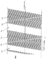
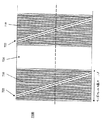
別の例に従うと、短い消去された領域によって分離される周期的なサーボフレームを有するサーボトラックパターンが設けられる。この例においては、サーボフレームは公知の距離および同期マーク(たとえば中間フレームマーク)によって分離された、サーボマークが繰返されるトーンフィールドを含む。この例においては、同期マークは、トーンフィールドに対して寸法およびアジマス方向が異なる中間フレームマークを含む。当該中間フレームマークはサーボフレームのトーンフィールドの上部に書込まれ、トーンフィールドとして同じ長手方向および横方向の寸法を占める。先の例と同様に、サーボトラックはテープの長さに沿って横方向に予め記録され、その幅にわたって複数のデータトラックインデックス位置を設けるために、書込まれたデータトラック幅に比べて幅が広い。図7Aおよび図7Bは、消去された帯域を含む2つの例示的なサーボトラックおよびサーボフレームパターンを示す。 According to another example, a servo track pattern having periodic servo frames separated by short erased areas is provided. In this example, the servo frame includes a tone field where the servo mark is repeated, separated by a known distance and sync mark (eg, an intermediate frame mark). In this example, the sync mark includes an intermediate frame mark that differs in size and azimuth direction relative to the tone field. The intermediate frame mark is written above the tone field of the servo frame and occupies the same longitudinal and lateral dimensions as the tone field. As in the previous example, the servo track is pre-recorded laterally along the length of the tape and has a width compared to the written data track width to provide a plurality of data track index positions across the width. wide. 7A and 7B show two exemplary servo tracks and servo frame patterns that include erased bands.
例示的なサーボトラック700Aおよび700Bは、DC消去された帯域724によって分離される繰返されたサーボフレームLfを含む。各サーボフレームLfは一定の磁束間隔トーン、すなわちトーンフィールド710を含み、これは、前述のとおり距離測定のために距離基準フィールドを与える。各フレームのトーンフィールド710内に、トーンフィールド710から区別され得る同期マーク722が埋込まれる。一例においては、同期マーク722の磁束空間間隔はトーンフィールド710の磁束空間間隔とは異なり、当該空間間隔は同期マーク722およびトーンフィールド710を識別するのに用いられる。他の例においては、同期マーク722は、当該同期マーク722がトーンフィールド710から区別され得るようにさまざまな磁束空間間隔などを備えた多くの磁束遷移を含み得る。
サーボ読取ヘッドがサーボトラックに沿って移動すると、これは、信号なしの(または比較的フラットな信号の)間隔で分離されるパルスのバーストを生成する。図8はサーボトラック800内における狭い読取ヘッドの経路を示し、これは図7Bのサーボトラック700Bに類似しており、結果として生じる読取信号が以下に示されるヘッドで生成されている。結果として生じる読取信号は上述の信号に類似しているが、ここでは、サーボフレームの先頭/終端をマークする信号内における消去された帯域間隔を含む。こうして、この例においては、消去された帯域724および同期マーク722は、サーボトラック800のために先頭フレーム同期マークおよび中間フレーム同期マークとしてそれぞれ機能する。
As the servo read head moves along the servo track, this produces bursts of pulses that are separated by no signal (or relatively flat signal) intervals. FIG. 8 shows a narrow read head path within
位置信号はサーボトラックから同様に得られ、検出チャネルによってデジタルパルスに変換され得る。当該パルスは好適なコントローラによって処理されて、トーンフィールド710と消去された帯域724と当該トーンフィールド710に埋込まれた同期マーク722とに関連付けられた間隔を得ることができる。一例においては、1ミクロンの間隔でトーンフィールド710におけるサーボマークを分離し、より長い1.5ミクロンの間隔で同期マーク722を識別する。
The position signal is similarly obtained from the servo track and can be converted to a digital pulse by the detection channel. The pulses can be processed by a suitable controller to obtain the spacing associated with the
サーボトラック700のトーンフィールド710、同期マーク722および消去された帯域724が識別されると、サーボトラック内におけるサーボ読取ヘッドの横方向の位置の計算が決定され得る。位置計算は図3に関連して記載されるものに類似していてもよい。
Once the
図7Aおよび図7Bを続けて参照すると、消去された帯域724を含むサーボトラック700Aおよび700Bが一例における1対のフォーマットされた記録ヘッドによって書込まれる。2つのフォーマットヘッドの磁気ギャップが異なるアジマス角を有し、テープの長さに沿って一方のヘッドを他方のヘッドの前にして長手方向に位置決めされる。当該ヘッドは第1のヘッドとして配置され、これは、基準トーンフィールド710のフレームを記録し、DC消去された帯域724によって分離される。第1のヘッドを追跡する第2のヘッドは、トーンフィールド710とは異なるアジマス角および間隔で記録されたサーボマーク722で基準トーンフィールド710を周期的に上書きする。2つのヘッドは、サーボマーク722を含みかつDC消去された帯域724で分離される基準トーンフィールド710のバーストで複合サーボトラックを作成する。サーボマーク722が埋込まれた基準トーンフィールド710のバーストがサーボフレームを形成し、これにより、前述のとおり横方向のヘッド位置を測定するための完全な情報の組が与えられる。
With continued reference to FIGS. 7A and 7B,
図9は、読取ヘッドの位置情報を得るための例示的な方法を示す。当該例示的な方法は図3に関連して記載されるものと類似しており、これに従って違いだけが述べられる。一例においては、サーボマークおよびDC消去された帯域の長さはトーンフィールド間隔の整数を与えるよう選択され、これにより、PLOが正味の位相エラーなしにこれらの領域を遷移させることが可能となる。加えて、PLOの位相エラーは、トーンが検出されている間隔中にサンプリングされ、同期マークおよび消去帯域の間隔中に一定に維持され得る。 FIG. 9 illustrates an exemplary method for obtaining read head position information. The exemplary method is similar to that described in connection with FIG. 3, and only the differences will be described accordingly. In one example, servo mark and DC erased band lengths are selected to give an integer number of tone field intervals, which allows the PLO to transition between these regions without a net phase error. In addition, the phase error of the PLO can be sampled during the interval in which tones are detected and kept constant during the interval between the sync mark and erase bands.
消去された帯域を含む例示的なサーボトラックは同様に速度情報を提供したり、符号化された長手方向の情報を含んだり、消去された帯域のない例と同様に記憶テープにわたってさまざまなフォーマットで構成されたりし得る。加えて、他のさまざまな識別可能な特徴が、上述のとおり長手方向の位置情報を与えるよう基準トーンまたは距離フィールド内に含まれてもよい。たとえば、サーボマーク、消去された帯域および基準トーンフィールド内における他の識別可能なマークのさまざまな組合せが可能でありかつ企図される。 An exemplary servo track containing erased bands will also provide velocity information, contain encoded longitudinal information, and in various formats across the storage tape as well as examples without erased bands. Can be configured. In addition, various other identifiable features may be included in the reference tone or distance field to provide longitudinal position information as described above. For example, various combinations of servo marks, erased bands, and other identifiable marks within the reference tone field are possible and contemplated.
上述の詳細な説明は具体的な実施例を説明するために提供されており、制限することを意図するものではない。この発明の範囲内の多くの変更例および変形例が可能であることを当業者は理解するだろう。たとえば、この明細書中に記載されるさまざまな具体的な方法およびシステムは、この明細書中に記載されるかまたはたとえば光もしくは磁気サーボ方法およびシステムを含むか否かにかかわらず、単独で、または他のさまざまな位置および/もしくはサーボ方法およびシステムと組合せて用いられてもよい。加えて、特定の例が述べられ、これらの例が関連技術におけるいくつかの不利点にいかに対処するかが考慮される。しかしながら、この説明は、上述の不利点に実際に対処するかまたはこれらを解決する方法および/またはシステムに上述のさまざまな例を限定することを意図するものではない。 The above detailed description is provided to illustrate specific embodiments and is not intended to be limiting. Those skilled in the art will appreciate that many variations and modifications within the scope of the present invention are possible. For example, the various specific methods and systems described herein, whether or not described herein or including optical or magnetic servo methods and systems, alone, Or it may be used in combination with various other position and / or servo methods and systems. In addition, specific examples are described, and how these examples address some of the disadvantages in the related art is considered. However, this description is not intended to limit the various examples described above to methods and / or systems that actually address or solve the above disadvantages.
100 サーボトラック、101 サーボフレーム、110 トーンフィールド、120、同期マーク、122 同期マーク。 100 servo track, 101 servo frame, 110 tone field, 120, sync mark, 122 sync mark.
Claims (19)
前記トランスデューサヘッドに関連付けられる読取要素から読取信号を生成するステップを含み、当該読取信号は磁気記憶媒体に記憶されたサーボトラックから生成され、前記サーボトラックは、
検出可能なサーボマークを形成する磁束遷移のサーボフレームを含み、前記サーボマークは、第1のアジマス角に向けられた、サーボマークが繰返されるトーンフィールドと、前記トーンフィールド内に組込まれた中間フレーム同期マークとを形成し、
前記トーンフィールドは前記サーボフレーム内における少なくとも2つの特徴間における寸法測定のために距離基準を提供し、
前記中間フレーム同期マークは前記トーンフィールドから区別可能であり、
前記中間フレーム同期マークの前と前記中間フレーム同期マークの後とにおける前記サーボトラックの長手方向に沿った各サーボフレームの前記トーンフィールドにおけるサーボマークの数が横方向の位置によって異なる、方法。 A method for sensing the position of a transducer head relative to a storage medium, comprising:
Generating a read signal from a read element associated with the transducer head, the read signal being generated from a servo track stored on a magnetic storage medium, the servo track comprising:
A servo frame of magnetic flux transitions forming a detectable servo mark, said servo mark being directed to a first azimuth angle, a tone field in which the servo mark is repeated, and an intermediate frame incorporated in said tone field Forming a sync mark and
The tone field provides a distance reference for dimensional measurements between at least two features in the servo frame;
The intermediate frame synchronization mark is distinguishable from the tone field;
The method wherein the number of servo marks in the tone field of each servo frame along the longitudinal direction of the servo track before and after the intermediate frame synchronization mark depends on the lateral position.
サーボトラックを読取り、前記記憶媒体に記録され、前記サーボトラックを表わす読取信号を生成するための、少なくとも1つの読取ヘッドを有するヘッドアセンブリと、
前記記憶媒体に対する前記ヘッドアセンブリの相対位置を調節するよう構成されるアク
チュエータと、
サーボコントローラとを含み、前記サーボコントローラは、
前記読取信号に基づいて前記アクチュエータを制御するよう構成され、前記サーボコントローラは前記サーボトラック内におけるサーボフレームを識別し、サーボマークが繰返されるトーンフィールドを有する各サーボフレームは、寸法測定のための距離基準とサーボマークが繰返されるトーンフィールド内における中間フレーム同期マークとを提供し、前記中間フレーム同期マークは前記トーンフィールドから区別可能であり、前記中間フレーム同期マークの前および前記中間フレーム同期マークの後における前記サーボトラックの長手方向に沿った前記サーボフレームの前記トーンフィールドにおけるサーボマークの数は横方向の位置によって異なり、前記サーボコントローラはさらに、
前記中間フレーム同期マークの前および前記中間フレーム同期マークの後におけるサーボマークの数に基づいて前記サーボトラックに対する前記読取ヘッドの相対位置を決定するよう構成される、サーボ制御システム。 A servo control system for positioning a magnetic head proximate to a surface of a magnetic storage medium for reading a servo pattern recorded in a longitudinal direction on the magnetic storage medium,
A head assembly having at least one read head for reading a servo track, generating a read signal recorded on the storage medium and representative of the servo track;
An actuator configured to adjust a relative position of the head assembly with respect to the storage medium;
A servo controller, the servo controller comprising:
The servo controller is configured to control the actuator based on the read signal, the servo controller identifies a servo frame in the servo track, and each servo frame having a tone field in which the servo mark is repeated is a distance for dimension measurement. Providing a reference and an intermediate frame synchronization mark in a tone field in which the servo mark is repeated, wherein the intermediate frame synchronization mark is distinguishable from the tone field, and before the intermediate frame synchronization mark and after the intermediate frame synchronization mark The number of servo marks in the tone field of the servo frame along the longitudinal direction of the servo track at different according to the lateral position, the servo controller further comprising:
A servo control system configured to determine a relative position of the read head relative to the servo track based on the number of servo marks before the intermediate frame synchronization mark and after the intermediate frame synchronization mark.
第1の記録要素および第2の記録要素に対して長手方向に磁気記憶媒体を移動させるステップを含み、前記第1の記録要素および前記第2の記録要素は前記長手方向に沿って位置合わせされ、異なるアジマス角に向けられ、前記方法はさらに、
前記第1の記録要素および前記第2の記録要素においてパルスを生成して、サーボトラックを形成するサーボフレームを書込むステップを含み、各サーボフレーム内において、前記第1の記録要素がサーボマークが繰返されるトーンフィールドを書込み、前記第2の記録要素が前記トーンフィールドの一部に同期マークを上書きし、このため、前記中間フレーム同期マークの前および前記中間フレーム同期マークの後における前記サーボトラックの長手方向に沿った各サーボフレームの前記トーンフィールドにおけるサーボマークの数が横方向の位置によって異なる、方法。 A method for writing a longitudinal servo track on a magnetic storage medium, comprising:
Moving the magnetic storage medium in a longitudinal direction relative to the first recording element and the second recording element, the first recording element and the second recording element being aligned along the longitudinal direction Directed to different azimuth angles, the method further comprising:
Generating a pulse in the first recording element and the second recording element to write a servo frame forming a servo track, in each servo frame, the first recording element has a servo mark Write a repeated tone field and the second recording element overwrites a portion of the tone field with a sync mark, so that the servo track before and after the intermediate frame sync mark The method, wherein the number of servo marks in the tone field of each servo frame along the longitudinal direction depends on the lateral position.
検出可能なサーボマークを形成する磁束遷移を含み、前記サーボマークは第1のアジマス角に向けられた、サーボマークが繰返されるトーンフィールドを形成し、これにより、前記トーンフィールドは、サーボトラックの特徴間における寸法測定のために距離基準を
提供する、磁気記憶媒体。 A magnetic storage medium comprising longitudinal servo tracks, the servo tracks comprising:
Including a magnetic flux transition that forms a detectable servo mark, wherein the servo mark is directed to a first azimuth angle to form a tone field in which the servo mark is repeated, whereby the tone field is characterized by a servo track A magnetic storage medium that provides a distance reference for dimensional measurements between.
前記中間フレーム同期マークは前記トーンフィールドから区別可能であり、各サーボフレームについては、前記中間フレーム同期マークの前および前記中間フレーム同期マークの後における前記サーボトラックの長手方向に沿った前記サーボフレームの前記トーンフィールドにおけるサーボマークの数が横方向の位置によって異なる、請求項18に記載の磁気記憶媒体。 The servo track further includes a servo frame of the tone field having an intermediate frame synchronization mark embedded in the tone field;
The intermediate frame synchronization mark is distinguishable from the tone field, and for each servo frame, the servo frame along the longitudinal direction of the servo track before the intermediate frame synchronization mark and after the intermediate frame synchronization mark. The magnetic storage medium according to claim 18, wherein the number of servo marks in the tone field varies depending on a lateral position.
Applications Claiming Priority (1)
| Application Number | Priority Date | Filing Date | Title |
|---|---|---|---|
| US10/854,078 US7158338B2 (en) | 2004-05-24 | 2004-05-24 | Servo track having periodic frames of tone field and embedded synchronization marks |
Publications (1)
| Publication Number | Publication Date |
|---|---|
| JP2005339775A true JP2005339775A (en) | 2005-12-08 |
Family
ID=34941427
Family Applications (1)
| Application Number | Title | Priority Date | Filing Date |
|---|---|---|---|
| JP2005149525A Pending JP2005339775A (en) | 2004-05-24 | 2005-05-23 | Method for sensing transducer head position to storage medium, servo control system for positioning magnetic head proximately to surface of magnetic storage medium, method for writing longitudinal servo track in magnetic storage medium, and magnetic storage medium including longitudinal servo track |
Country Status (3)
| Country | Link |
|---|---|
| US (4) | US7158338B2 (en) |
| EP (1) | EP1600967A3 (en) |
| JP (1) | JP2005339775A (en) |
Cited By (2)
| Publication number | Priority date | Publication date | Assignee | Title |
|---|---|---|---|---|
| JP2011512608A (en) * | 2008-02-19 | 2011-04-21 | インターナショナル・ビジネス・マシーンズ・コーポレーション | Tape storage system having error correction function of longitudinal position data, method of encoding error correction function, and program thereof |
| JP2011514617A (en) * | 2008-03-20 | 2011-05-06 | インターナショナル・ビジネス・マシーンズ・コーポレーション | Sequential data storage medium containing longitudinal position information and method for encoding the longitudinal position information in the medium |
Families Citing this family (19)
| Publication number | Priority date | Publication date | Assignee | Title |
|---|---|---|---|---|
| US7158338B2 (en) * | 2004-05-24 | 2007-01-02 | Quantum Corporation | Servo track having periodic frames of tone field and embedded synchronization marks |
| US7362525B2 (en) * | 2005-07-22 | 2008-04-22 | Quantum Corporation | PRML based magnetic servo position demodulator |
| US7428118B2 (en) * | 2005-11-28 | 2008-09-23 | Quantum Corporation | LTM compensation methods and systems for magnetic servo writing |
| US7477474B2 (en) | 2007-03-28 | 2009-01-13 | Quantum Corporation | Servo writing and decoding position error signal for linear tape drives |
| US7773333B2 (en) * | 2007-08-10 | 2010-08-10 | International Business Machines Corporation | Recording data simultaneously at two depths of a tilted magnetic medium |
| US7848039B2 (en) * | 2007-08-11 | 2010-12-07 | Hitachi Global Storage Technologies Netherlands B.V. | Magnetic recording disk and disk drive with patterned phase-type servo fields for read/write head positioning |
| US7586709B2 (en) * | 2007-09-28 | 2009-09-08 | Hitachi Global Storage Technologies Netherlands B.V. | Read write offset error correction using geometric reference in self servo write process |
| JP5063377B2 (en) * | 2008-01-10 | 2012-10-31 | インターナショナル・ビジネス・マシーンズ・コーポレーション | Apparatus and method for writing / reading data to / from tape medium |
| US7990644B2 (en) * | 2008-02-29 | 2011-08-02 | International Business Machines Corporation | Apparatus and method to decode linear position information encoded in a sequential information storage medium |
| US7864487B2 (en) * | 2008-05-09 | 2011-01-04 | International Business Machines Corporation | Head design for writing servo patterns on magnetic tape |
| US7881008B2 (en) * | 2008-05-09 | 2011-02-01 | International Business Machines Corporation | Joint specification of servo format and servo reader parameters for tape drive systems |
| KR101397738B1 (en) * | 2008-06-18 | 2014-05-20 | 인터내셔널 비지네스 머신즈 코포레이션 | Servo control in tape drives |
| US8913340B2 (en) * | 2008-06-18 | 2014-12-16 | International Business Machines Corporation | Systems and methods for writing servo patterns |
| US7929243B2 (en) * | 2009-02-06 | 2011-04-19 | International Business Machines Corporation | Setting edge stress signal in magnetic tape data storage cartridge memory in response to servo detection error signals |
| US8339726B2 (en) * | 2009-12-22 | 2012-12-25 | Quantum Corporation | Unique media identifier |
| US8446684B2 (en) | 2010-01-21 | 2013-05-21 | International Business Machines Corporation | Magnetic tape servo format allowing for increased linear tape density and systems thereof |
| US8139312B2 (en) | 2010-03-02 | 2012-03-20 | International Business Machines Corporation | Timing alternative intervals within a timing based servo band |
| GB2496006A (en) | 2011-10-28 | 2013-05-01 | Ibm | Longitudinal position information on a magnetic tape media |
| US10614846B1 (en) | 2019-05-17 | 2020-04-07 | International Business Machines Corporation | Measuring servo reader span on a magnetic recording head |
Citations (3)
| Publication number | Priority date | Publication date | Assignee | Title |
|---|---|---|---|---|
| JP2001006140A (en) * | 1999-05-19 | 2001-01-12 | Internatl Business Mach Corp <Ibm> | Servo-gap detector, detecting method and servo system |
| JP2002074631A (en) * | 2000-08-16 | 2002-03-15 | Internatl Business Mach Corp <Ibm> | Tape drive and servo system stabilizing method thereof |
| JP2003257009A (en) * | 2002-03-01 | 2003-09-12 | Imation Corp | Servo positioning method for time base |
Family Cites Families (65)
| Publication number | Priority date | Publication date | Assignee | Title |
|---|---|---|---|---|
| US3845500A (en) * | 1973-11-12 | 1974-10-29 | Ibm | Head to track alignment in a rotating head magnetic tape unit |
| US4616574A (en) * | 1984-05-25 | 1986-10-14 | Empire State Electric Energy Research Corp. (Eseerco) | Process for treating combustion systems with pressure-hydrated dolomitic lime |
| US4616275A (en) * | 1984-10-22 | 1986-10-07 | Priam Corporation | Disc servo with 1F-2F servo pattern |
| US5371638A (en) | 1992-06-24 | 1994-12-06 | Digital Equipment Corporation | Servo method and apparatus for very high track density magnetic recording by adjusting head position based on servo information read from adjacent track |
| US5314913A (en) | 1992-12-08 | 1994-05-24 | American Home Products Corporation | 4- or 5-(substituted sulfonyl)methyl-3(2H)-furanones |
| US5384671A (en) * | 1993-12-23 | 1995-01-24 | Quantum Corporation | PRML sampled data channel synchronous servo detector |
| US5452165A (en) * | 1994-03-16 | 1995-09-19 | International Business Machines Corporation | Close packed magnetic head linear array |
| US5689384A (en) | 1994-06-30 | 1997-11-18 | International Business Machines Corporation | Timing based servo system for magnetic tape systems |
| US5576906A (en) | 1994-10-11 | 1996-11-19 | Quantum Corporation | Synchronous detection of concurrent servo bursts for fine head position in disk drive |
| DE4446431C2 (en) * | 1994-12-23 | 1998-05-07 | Siemens Ag | Process for direct manipulation of images on a monitor with a mouse |
| JPH09167456A (en) | 1995-12-15 | 1997-06-24 | Fujitsu Ltd | Disk device and disk medium |
| WO1997027703A1 (en) * | 1996-01-26 | 1997-07-31 | Exabyte Corporation | Multipurpose digital recording method and apparatus and media therefor |
| WO1997033279A1 (en) * | 1996-03-05 | 1997-09-12 | Sony Corporation | Tracking controller for a tape-like recording medium |
| JP3724055B2 (en) * | 1996-05-10 | 2005-12-07 | ブラザー工業株式会社 | Motor control device |
| US6018434A (en) | 1997-01-14 | 2000-01-25 | Quantum Corporation | Tape cartridge having written-in-defect servo patterns for rapid head position calibration |
| US6023385A (en) * | 1997-02-21 | 2000-02-08 | Storage Technology Corporation | Tape servo pattern with enhanced synchronization properties |
| US5898533A (en) | 1997-02-21 | 1999-04-27 | Storage Technology Corporation | Tape servo pattern with embedded servo track number identification |
| US5930065A (en) * | 1997-05-16 | 1999-07-27 | International Business Machines Corporation | Timing based servo longitudinal addressing |
| JP3670440B2 (en) | 1997-05-20 | 2005-07-13 | 富士通株式会社 | Position detection method on disk, disk device, and disk |
| US6108159A (en) | 1997-07-14 | 2000-08-22 | Quantum Corporation | Data track edge follower servo method and apparatus |
| US6035040A (en) * | 1997-10-17 | 2000-03-07 | Nortel Networks Corporation | System and method for decryption in the symbol domain |
| US6023386A (en) | 1997-10-31 | 2000-02-08 | Cirrus Logic, Inc. | Fault tolerant sync mark detector for synchronizing a time varying sequence detector in a sampled amplitude read channel |
| US6111719A (en) | 1998-03-06 | 2000-08-29 | Hewlett-Packard Company | Linear speed measurement independent of lateral position in linear tape systems |
| US6246535B1 (en) | 1998-11-13 | 2001-06-12 | Quantum Corporation | Optical apparatus for tracking a magnetic tape |
| US6542325B1 (en) | 1999-03-10 | 2003-04-01 | Imation Corp. | Time-based servo for magnetic storage media |
| US6657802B1 (en) * | 1999-04-16 | 2003-12-02 | Infineon Technologies Corporation | Phase assisted synchronization detector |
| US6327105B1 (en) | 1999-06-23 | 2001-12-04 | Iomega Corporation | Apparatus and methods for low overhead, highly reliable determination of position of a magnetic storage medium |
| US6606728B1 (en) * | 1999-06-23 | 2003-08-12 | Agere Systems Inc. | Rate (M/N) code encoder, detector, and decoder for control data |
| US6538182B1 (en) * | 1999-07-06 | 2003-03-25 | Senesco, Inc. | DNA encoding a plant deoxyhypusine synthase, a plant eukaryotic initiation factor 5A, transgenic plants and a method for controlling senescence programmed and cell death in plants |
| US6239939B1 (en) | 1999-08-09 | 2001-05-29 | International Business Machines Corporation | Robust detection of data modulated into a timing based servo |
| US6512651B1 (en) * | 2000-07-11 | 2003-01-28 | Storage Technology Corporation | Helical scan tape track following |
| US6580581B1 (en) | 2000-08-16 | 2003-06-17 | International Business Machines Corporation | Recovery of lateral position of a servo system with respect to longitudinal servo bands of a magnetic tape |
| US6721126B1 (en) * | 2000-08-16 | 2004-04-13 | International Business Machines Corporation | Position identification for a coarse actuator portion of a compound actuator |
| JP4348851B2 (en) * | 2000-09-21 | 2009-10-21 | ソニー株式会社 | Recording medium, disk recording apparatus and method, and disk reproducing apparatus and method |
| US6839196B2 (en) | 2001-05-24 | 2005-01-04 | Quantum Corporation | Magnetic track following servo algorithm using signal quality |
| US6865050B2 (en) | 2001-06-07 | 2005-03-08 | Fuji Photo Film Co., Ltd. | Servo signal recording device and servo signal verifying device using edge detection |
| US6781778B1 (en) * | 2001-07-16 | 2004-08-24 | Imation Corp. | Time-based sectored servo data format |
| US6762900B2 (en) * | 2001-07-17 | 2004-07-13 | International Business Machines Corporation | Method and apparatus for performing position error signal conditioning of LTO media servo format written-in velocity variation |
| US6791781B2 (en) | 2001-07-17 | 2004-09-14 | International Business Machines Corporation | Method and apparatus for providing linear position (LPOS) estimations |
| US6856484B2 (en) | 2001-09-05 | 2005-02-15 | Quantum Corporation | Magnetic servo of a recording head |
| US6760173B2 (en) | 2001-09-27 | 2004-07-06 | Texas Instruments Incorporation | Synchronization servo mark detector and method having improved phase error immunity for use in mass data storage device, or the like |
| US6775092B2 (en) * | 2001-12-07 | 2004-08-10 | Quantum Corporation | Lateral tape motion sensor |
| US6710967B2 (en) * | 2001-12-28 | 2004-03-23 | Storage Technology Corporation | High frequency and low frequency servo pattern |
| US6721156B2 (en) * | 2002-01-11 | 2004-04-13 | Illinois Tool Works Inc. | Primary/secondary wireless protector |
| US6879457B2 (en) * | 2002-02-13 | 2005-04-12 | International Business Machines Corporation | Timing based servo with fixed distances between transitions |
| US6912104B2 (en) * | 2002-04-30 | 2005-06-28 | Storage Technology Corporation | Timing based servo pattern incorporating band encoding |
| US7130140B1 (en) | 2002-05-06 | 2006-10-31 | Storage Technology Corporation | Polarity encoded pattern for timing based servo |
| US7139151B2 (en) * | 2003-03-03 | 2006-11-21 | Imation Corp. | Band identification in time-based servopositioning formats |
| US7106544B2 (en) * | 2003-05-09 | 2006-09-12 | Advanced Research Corporation | Servo systems, servo heads, servo patterns for data storage especially for reading, writing, and recording in magnetic recording tape |
| US7035040B2 (en) * | 2003-05-16 | 2006-04-25 | Imation Corp. | Sequenced time-based servo techniques |
| US7002763B2 (en) | 2003-08-08 | 2006-02-21 | International Business Machines Corporation | Identification of laterally positioned servo bands employing differentiating characteristics of servo patterns |
| JP2005085421A (en) * | 2003-09-11 | 2005-03-31 | Fuji Photo Film Co Ltd | Magnetic tape and its manufacturing method, servo writer, and servo signal writing method |
| US7171702B2 (en) * | 2003-10-01 | 2007-02-06 | H2O Guard, Inc. | Toilet tank fill valve and method of operation |
| US7139152B2 (en) | 2003-10-20 | 2006-11-21 | Quantum Corporation | Servo methods and systems using existing data structures and optical masks |
| US7149050B2 (en) * | 2003-10-20 | 2006-12-12 | Quantum Corporation | Diffractive position sensors and control systems |
| US7085095B2 (en) | 2003-10-20 | 2006-08-01 | Quantum Corporation | Electromagnetic void-sensing probes and position control systems |
| US7116514B2 (en) | 2003-10-20 | 2006-10-03 | Quantum Corporation | Methods and systems for magnetic recording |
| US7136255B2 (en) | 2003-10-20 | 2006-11-14 | Quantum Corporation | Servo methods and systems using masked medium edge position sensors |
| US7102845B2 (en) | 2003-10-20 | 2006-09-05 | Quantum Corporation | Servo methods and systems using existing data structures and medium edge position |
| US7038872B2 (en) * | 2003-11-10 | 2006-05-02 | Imation Corp. | Servo patterns with inherent track ID |
| US7158338B2 (en) | 2004-05-24 | 2007-01-02 | Quantum Corporation | Servo track having periodic frames of tone field and embedded synchronization marks |
| US7095583B2 (en) | 2004-06-02 | 2006-08-22 | Imation Corp. | Dual mode servo pattern |
| US7199958B2 (en) * | 2004-08-25 | 2007-04-03 | Imation Corp. | Servo head with varying write gap width |
| US7362525B2 (en) | 2005-07-22 | 2008-04-22 | Quantum Corporation | PRML based magnetic servo position demodulator |
| US7428118B2 (en) * | 2005-11-28 | 2008-09-23 | Quantum Corporation | LTM compensation methods and systems for magnetic servo writing |
-
2004
- 2004-05-24 US US10/854,078 patent/US7158338B2/en not_active Expired - Fee Related
-
2005
- 2005-05-23 JP JP2005149525A patent/JP2005339775A/en active Pending
- 2005-05-23 EP EP05253172A patent/EP1600967A3/en not_active Withdrawn
-
2006
- 2006-11-20 US US11/602,871 patent/US7245453B2/en not_active Expired - Fee Related
- 2006-11-20 US US11/602,872 patent/US7522372B2/en active Active
- 2006-11-20 US US11/602,693 patent/US7522371B2/en active Active
Patent Citations (3)
| Publication number | Priority date | Publication date | Assignee | Title |
|---|---|---|---|---|
| JP2001006140A (en) * | 1999-05-19 | 2001-01-12 | Internatl Business Mach Corp <Ibm> | Servo-gap detector, detecting method and servo system |
| JP2002074631A (en) * | 2000-08-16 | 2002-03-15 | Internatl Business Mach Corp <Ibm> | Tape drive and servo system stabilizing method thereof |
| JP2003257009A (en) * | 2002-03-01 | 2003-09-12 | Imation Corp | Servo positioning method for time base |
Cited By (2)
| Publication number | Priority date | Publication date | Assignee | Title |
|---|---|---|---|---|
| JP2011512608A (en) * | 2008-02-19 | 2011-04-21 | インターナショナル・ビジネス・マシーンズ・コーポレーション | Tape storage system having error correction function of longitudinal position data, method of encoding error correction function, and program thereof |
| JP2011514617A (en) * | 2008-03-20 | 2011-05-06 | インターナショナル・ビジネス・マシーンズ・コーポレーション | Sequential data storage medium containing longitudinal position information and method for encoding the longitudinal position information in the medium |
Also Published As
| Publication number | Publication date |
|---|---|
| US7158338B2 (en) | 2007-01-02 |
| US7522371B2 (en) | 2009-04-21 |
| US7245453B2 (en) | 2007-07-17 |
| EP1600967A2 (en) | 2005-11-30 |
| US20070070545A1 (en) | 2007-03-29 |
| US20070064327A1 (en) | 2007-03-22 |
| US7522372B2 (en) | 2009-04-21 |
| US20070064328A1 (en) | 2007-03-22 |
| US20050259349A1 (en) | 2005-11-24 |
| EP1600967A3 (en) | 2010-03-10 |
Similar Documents
| Publication | Publication Date | Title |
|---|---|---|
| JP2005339775A (en) | Method for sensing transducer head position to storage medium, servo control system for positioning magnetic head proximately to surface of magnetic storage medium, method for writing longitudinal servo track in magnetic storage medium, and magnetic storage medium including longitudinal servo track | |
| US7428118B2 (en) | LTM compensation methods and systems for magnetic servo writing | |
| KR101397738B1 (en) | Servo control in tape drives | |
| JP5607609B2 (en) | Servo control system | |
| US8848310B2 (en) | Offset correction values on a data storage media | |
| US20140139944A1 (en) | Information storage using servo patterns | |
| US20030151844A1 (en) | Timing based servo with fixed distances between transitions | |
| JP2009151851A (en) | Magnetic tape, magnetic tape apparatus, servo pattern recording apparatus, magnetic tape producing method, and recording method | |
| EP1526512A1 (en) | Servo methods and systems using existing data structures and optical masks | |
| US7116514B2 (en) | Methods and systems for magnetic recording | |
| JP2008243361A (en) | Apparatus for writing longitudinal servo track on magnetic medium | |
| US7259930B2 (en) | Apparatus for transporting a magnetic tape | |
| US7102845B2 (en) | Servo methods and systems using existing data structures and medium edge position | |
| US7495859B2 (en) | Interleaved servo pattern | |
| JP5309202B2 (en) | Magnetic tape | |
| JP4918407B2 (en) | Servo signal recording device | |
| JP4404038B2 (en) | Linear tape and linear tape drive device and linear tape servo pattern writing device | |
| EP0940812A2 (en) | Absolute longitudinal position encoding in linear tape systems | |
| US8059361B2 (en) | Position signal processor | |
| JP2010182411A (en) | Magnetic tape and servo pattern recording apparatus | |
| JP2008065935A (en) | Disk recording medium and information recording device | |
| JP4940418B2 (en) | Magnetic storage device and magnetic storage medium | |
| JP2004259395A (en) | Magnetic recording/reproducing device | |
| JP2004039073A (en) | Reference signal generating device in magnetic recording device |
Legal Events
| Date | Code | Title | Description |
|---|---|---|---|
| A621 | Written request for application examination |
Free format text: JAPANESE INTERMEDIATE CODE: A621 Effective date: 20080516 |
|
| A977 | Report on retrieval |
Free format text: JAPANESE INTERMEDIATE CODE: A971007 Effective date: 20110201 |
|
| A131 | Notification of reasons for refusal |
Free format text: JAPANESE INTERMEDIATE CODE: A131 Effective date: 20110222 |
|
| A521 | Written amendment |
Free format text: JAPANESE INTERMEDIATE CODE: A523 Effective date: 20110520 |
|
| A02 | Decision of refusal |
Free format text: JAPANESE INTERMEDIATE CODE: A02 Effective date: 20111025 |