JP2005338076A - System using polarization operation retroreflector - Google Patents
System using polarization operation retroreflector Download PDFInfo
- Publication number
- JP2005338076A JP2005338076A JP2005144359A JP2005144359A JP2005338076A JP 2005338076 A JP2005338076 A JP 2005338076A JP 2005144359 A JP2005144359 A JP 2005144359A JP 2005144359 A JP2005144359 A JP 2005144359A JP 2005338076 A JP2005338076 A JP 2005338076A
- Authority
- JP
- Japan
- Prior art keywords
- polarization
- retroreflector
- reflected
- path
- disposed
- Prior art date
- Legal status (The legal status is an assumption and is not a legal conclusion. Google has not performed a legal analysis and makes no representation as to the accuracy of the status listed.)
- Pending
Links
Images


Classifications
-
- G—PHYSICS
- G01—MEASURING; TESTING
- G01B—MEASURING LENGTH, THICKNESS OR SIMILAR LINEAR DIMENSIONS; MEASURING ANGLES; MEASURING AREAS; MEASURING IRREGULARITIES OF SURFACES OR CONTOURS
- G01B9/00—Measuring instruments characterised by the use of optical techniques
- G01B9/02—Interferometers
- G01B9/02015—Interferometers characterised by the beam path configuration
- G01B9/02017—Interferometers characterised by the beam path configuration with multiple interactions between the target object and light beams, e.g. beam reflections occurring from different locations
- G01B9/02019—Interferometers characterised by the beam path configuration with multiple interactions between the target object and light beams, e.g. beam reflections occurring from different locations contacting different points on same face of object
-
- G—PHYSICS
- G01—MEASURING; TESTING
- G01B—MEASURING LENGTH, THICKNESS OR SIMILAR LINEAR DIMENSIONS; MEASURING ANGLES; MEASURING AREAS; MEASURING IRREGULARITIES OF SURFACES OR CONTOURS
- G01B9/00—Measuring instruments characterised by the use of optical techniques
- G01B9/02—Interferometers
- G01B9/02041—Interferometers characterised by particular imaging or detection techniques
- G01B9/02045—Interferometers characterised by particular imaging or detection techniques using the Doppler effect
-
- G—PHYSICS
- G01—MEASURING; TESTING
- G01B—MEASURING LENGTH, THICKNESS OR SIMILAR LINEAR DIMENSIONS; MEASURING ANGLES; MEASURING AREAS; MEASURING IRREGULARITIES OF SURFACES OR CONTOURS
- G01B9/00—Measuring instruments characterised by the use of optical techniques
- G01B9/02—Interferometers
- G01B9/02055—Reduction or prevention of errors; Testing; Calibration
- G01B9/02056—Passive reduction of errors
- G01B9/02059—Reducing effect of parasitic reflections, e.g. cyclic errors
-
- G—PHYSICS
- G01—MEASURING; TESTING
- G01B—MEASURING LENGTH, THICKNESS OR SIMILAR LINEAR DIMENSIONS; MEASURING ANGLES; MEASURING AREAS; MEASURING IRREGULARITIES OF SURFACES OR CONTOURS
- G01B2290/00—Aspects of interferometers not specifically covered by any group under G01B9/02
- G01B2290/15—Cat eye, i.e. reflection always parallel to incoming beam
-
- G—PHYSICS
- G01—MEASURING; TESTING
- G01B—MEASURING LENGTH, THICKNESS OR SIMILAR LINEAR DIMENSIONS; MEASURING ANGLES; MEASURING AREAS; MEASURING IRREGULARITIES OF SURFACES OR CONTOURS
- G01B2290/00—Aspects of interferometers not specifically covered by any group under G01B9/02
- G01B2290/70—Using polarization in the interferometer
Abstract
Description
本発明は概して干渉計システムに関し、詳しくは、測定ビームと基準ビームの望ましくない混合を低減する干渉計システムに関する。 The present invention relates generally to interferometer systems, and more particularly to an interferometer system that reduces undesirable mixing of measurement and reference beams.
光学測定システムでは、光ビームの偏光成分を分離し、分離した成分を異なる目的に使用することが多い。例えば干渉計は、偏光成分を分離し、ある偏光成分を測定対象の物体で反射させるための測定ビームとして使用し、もう1つの直交偏光成分で、測定ビームの比較対象となる基準ビームを形成する場合がある。偏光成分を使用する利点は、2つのビーム成分を同一線上に配置し、必要に応じて同じ共通モードを共有し、偏光ビームスプリッタを用いてそれらを分離または再結合できる点にある。但し、そのような測定システムでは、ビーム成分同士の混合の原因となる偏光変化を回避するために、ビーム成分の偏光を慎重に制御する必要がある。 Optical measurement systems often separate the polarization components of a light beam and use the separated components for different purposes. For example, an interferometer separates polarization components, uses one polarization component as a measurement beam to reflect off the object being measured, and forms another reference beam with which the other orthogonal polarization component is compared. There is a case. The advantage of using polarization components is that the two beam components can be placed on the same line, share the same common mode as needed, and can be separated or recombined using a polarizing beam splitter. However, in such a measurement system, it is necessary to carefully control the polarization of the beam components in order to avoid polarization changes that cause mixing of the beam components.
干渉計における偏光混合の1つの影響は一般に、周期的誤差または周期的非線形性と呼ばれる。例えば特許文献1および特許文献2は、測定ビームまたは基準ビームの偏光変化によって基準ビームと測定ビームとの間に偏光漏洩が発生し、その結果、周期的な非線形性または測定誤差が発生する可能性がある干渉計について記載している。そうした干渉計における偏光変化の原因には、偏光ビームスプリッタの不完全な偏光コーティング、偏光を所望の状態に変化させることができない不完全なリターデーションプレート、およびコーナキューブ・レトロリフレクタなどのレトロリフレクタなどがある。
One effect of polarization mixing in an interferometer is commonly referred to as periodic error or periodic nonlinearity. For example, in
立体型コーナーキューブ・リフレクタなどのレトロリフレクタは一般に、入射ビームの角度とは無関係に、入射ビームに対して平行な反射ビームを返す。レトロリフレクタが様々な光学系に有用である理由は、この特性にある。しかしながら、コーティングされていない立体型コーナーキューブ・リフレクタは一般に、入射ビームの偏光状態を維持することができない。立体型コーナーキューブ・リフレクタに反射コーティング(例えば、銀コーティングなど)を施して偏光変化を緩和または極小化することも可能ではあるが、コーティングされたコーナーキューブ・リフレクタに残存する偏光変化は、依然として、偏光成分を分離する測定システムの精度または正確性を制約する要因となりうる。 Retro-reflectors, such as solid corner cube reflectors, generally return a reflected beam that is parallel to the incident beam, regardless of the angle of the incident beam. This is the reason why retro reflectors are useful for various optical systems. However, uncoated solid corner cube reflectors are generally unable to maintain the polarization state of the incident beam. Although it is possible to reduce or minimize the polarization change by applying a reflective coating (eg, silver coating) to the solid corner cube reflector, the polarization change remaining in the coated corner cube reflector is still It can be a factor that limits the accuracy or accuracy of the measurement system that separates the polarization components.
従って、レトロリフレクタを使用し、且つ、偏光成分の望ましくない混合を回避することが可能な高精度光学システムが必要とされている。 Therefore, there is a need for a high precision optical system that uses a retroreflector and that can avoid undesired mixing of polarization components.
本発明の一態様によれば、1以上の偏光操作要素を有するコーナーキューブ・リフレクタは、反射ビームの偏光を制御して入射ビームの偏光を維持または変換し、出力ビームの偏光を所望の偏光にする。偏光成分を分離する測定システムは、コーティングされていないコーナーキューブ・リフレクタを使用しても、偏光成分の望ましくない混合を低レベルに抑えた高精度の測定を行なうことができる。 In accordance with one aspect of the present invention, a corner cube reflector having one or more polarization manipulation elements controls the polarization of the reflected beam to maintain or convert the polarization of the incident beam and the polarization of the output beam to the desired polarization. To do. The measurement system that separates the polarization components can perform high-precision measurements with a low level of undesirable mixing of the polarization components, even if an uncoated corner cube reflector is used.
本発明の他の態様によれば、測定システムは、金属コーティングされたコーナーキューブ・リフレクタを使用する。コーナキューブ・リフレクタは、別々に向き調節可能なリターデーションプレートを備え、所望の偏光操作を実現する。 According to another aspect of the invention, the measurement system uses a metal coated corner cube reflector. The corner cube reflector has a retardation plate that can be individually oriented to achieve the desired polarization operation.
添付の図面において、同一の参照符号は類似の要素または同一の要素を意味する。 In the accompanying drawings, the same reference signs refer to similar or identical elements.
本発明の一態様によれば、偏光成分を分離する光学測定システムは、望ましくない偏光解消を引き起こすことなく入射ビームの偏光を維持または変換するレトロリフレクタを使用することができる。測定システムの各レトロリフレクタは、リターデーションプレート、光学回転子、またはファラデー回転子などの1以上の偏光操作要素を備えた立体型コーナーキューブを有する。偏光操作要素は、入射ビームおよび/または反射ビームの偏光を操作し、所望の偏光維持または偏光変換を行なう。 According to one aspect of the invention, an optical measurement system that separates polarization components can use a retroreflector that maintains or converts the polarization of the incident beam without causing undesired depolarization. Each retro-reflector of the measurement system has a solid corner cube with one or more polarization manipulation elements such as a retardation plate, an optical rotator, or a Faraday rotator. The polarization manipulating element manipulates the polarization of the incident beam and / or reflected beam to provide the desired polarization maintenance or polarization conversion.
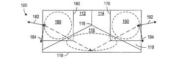
図1Aおよび図1Bはそれぞれ、トリミングされたコーナーキューブ・リフレクタ100の正面図および背面図を示す。コーナーキューブ・リフレクタ100は、3つの平坦な反射面112、114、116と、前面118とを有するガラスその他の光学品質材料からなる立体ブロック110を含む。表面112、114および116は、キューブのコーナーにおける面の交差と同様に直角に交差し、前面118は、コーナーキューブの頂点115を通る対称軸に対して垂直であることが望ましい。図示のブロック110は、トリミングによって余分なガラスが除去され、面118が矩形になっている。代替として、ブロック110は、トリミングしなくてもよいし(即ち、三角形の面112、114、116および118を有する4面体のガラスブロック)、面118が他の形状(例えば円形など)になるようにトリミングしてもよい。
1A and 1B show a front view and a rear view of a trimmed
偏光操作要素160および170はそれぞれ、ブロック110の正面118を通る入射ビーム180および反射ビーム190の経路上にある。コーナーキューブ・リフレクタ100はレトロリフレクタであるから、コーナーキューブ・リフレクタ100からの反射ビーム190は、入射ビーム180の方向とは無関係に、入射ビーム180に対して平行かつ入射ビーム180からオフセットされる。
入射ビーム180がブロック110を通過する場合、入射ビーム180はまず表面112で反射され、次いで表面116で反射された後、最後に表面114で反射され、面118を通して反射ビーム190として外に導かれる。本発明の他の実施形態において、ブロック110は、その反射面112、114および116をコーティングしてもよいし(例えば、銀などの反射コーティング)、コーティングしなくてもよい(例えば、全体に内部反射が発生する)。偏光操作要素160および170として使用される光学要素の具体的種類は通常、ブロック110をコーティングするか否かによって決まる。
When
ブロック110をコーティングする実施形態の場合、ブロック110における反射プロセスにおいて、円偏光がほぼ維持される。この実施形態では、各偏光維持要素160および170として、1/4波長リターデーションプレートが使用される。測定システムに使用されるコンポーネントの直線偏光の偏光方向に対して45°の遅軸を有する1/4波長板は一般に、直交直線偏光成分を直交円偏光成分に変換する。具体的には、要素160は、直線偏光の入射ビーム180がブロック110に入射するときにその入射ビーム180を円偏光ビームに変更することができる。しかしながら、コーティングされたコーナーキューブ・リフレクタにおける反射は、円偏光をほぼ維持するだけに過ぎないので、反射ビーム190は、わずかに楕円の偏光を有するものとなる。要素190が直線偏光成分の偏光方向に対して45°にある場合、要素190は、円偏光ビームを直線偏光ビームに変換するが、楕円偏光は2つの直交する直線偏光の混合に変換される。
For the
本発明の一態様によれば、コーティングされたコーナーキューブ・リフレクタと共に使用される1/4波長板は、その向きを調節することができる。この実施形態では、要素160および170として、1/4波長板が使用される。1/4波長板の結晶軸は、偏光混合が最小になるように45°から離れた角度に調節されるため、測定システムにおける周期的誤差は最小限になる。
According to one aspect of the present invention, a quarter wave plate used with a coated corner cube reflector can be adjusted in orientation. In this embodiment, quarter wave plates are used as
ブロック110をコーティングしない実施形態、またはブロック110に少損失コーティング(例えば、薄い誘電体コーティング)を施す実施形態における反射プロセスでは、入射ビーム180の互いに直交する直線偏光182および184がそれぞれ、反射ビーム190の互いに直交する直線偏光192および194に変換される。具体的には、ブロック110をコーティングしない場合、または、ブロック110に少損失コーティングを施す場合、偏光182がコーナーキューブの材料の特性に応じて選択された特定の角度にあれば、ブロック110は、直線偏光の反射ビームを生成する。BK7から作成されたコーティングの施されていないコーナーキューブの場合、この角度は、表面112および114によって形成されるV字(楔)を二等分する面から約13.7°である。その場合、入力直線偏光182および184にそれぞれ対応する出力直線偏光192および194は、直交しているが、反対方向に約13.7°だけ回転している。本発明の一態様によれば、偏光操作要素160および170は、偏光182、184または192、194を回転させ、コーナーキューブ・リフレクタ100において入力ビームの偏光成分が維持されるようにすることが出来る。代替として、偏光操作要素160および170は、直線偏光の変換を制御し、出力偏光を入力偏光に対して既知の態様(例えば、90°の整数倍の角度だけ回転された状態)で異ならせることが出来る。
In a reflection process in an embodiment where the
ブロック110をコーティングしない実施形態、またはブロック110に少損失コーティングを施す本発明の一実施形態では、各偏光操作要素160または170として半波長リターデーションプレートが使用される。半波長リターデーションプレートは、要素160または170の遅軸の向きを調節できるように取り付けられる。この実施形態の場合、入力半波長板160はその場で調節され、ブロック100によって直線偏光の反射ビームが生成される向きに、直線偏光成分を回転させる。出力半波長板170を測定システムに使用する必要がある場合、出力半波長板170も同様にその場で調節され、生成される直線偏光の出力ビームを回転させる。
In embodiments where the
ブロック110をコーティングしない本発明の他の実施形態では、各偏光操作要素160または170として、偏光方向を必要量だけ回転させる光学式回転子またはファラデー回転子を使用し、測定システムにおける周期的な誤差または非線形性を最小限に抑える。光学式回転子またはファラデー回転子は、時間のかかるアライメントプロセスを必要とせずに、所望の量の回転機能を提供する。又、石英を利用した光学式回転子は一般に、波長板(例:約0.02mm)よりも厚い(例えば、約1mm)ので、取り扱いも容易である。
In other embodiments of the invention that do not coat
図2Aは、本発明の一実施形態による干渉計200を示す図である。干渉計200は、光源210、偏光ビームスプリッタ(PBS)220、基準反射器230、測定反射器240、および測定電子回路250を含む。干渉計200は、Agilent Technologies, Inc.が販売している「10702A linear interferometer」などの市販の干渉計に類似したものであってよいが、干渉計200は、基準反射器230および測定反射器240として偏光維持レトロリフレクタを使用している。
FIG. 2A shows an
光源210は一般に、レーザーや、干渉計200に必要とされる特性を有する入射光ビームIBの他の発生源である。光源210には、例えば、HeNeレーザーや、入力ビームIBにとって望ましい波長、強度、および偏光を有するコヒーレントな単色ビームの他の何らかの発生源が使用される。ヘテロダイン干渉計の場合、光源210には、ゼーマン・レーザー(Zeeman split laser)や、互いに僅かに異なる波長の2つの直交する偏光成分を有する入力ビームIBを生成する他の何らかの発生源が使用される。
The
偏光ビームスプリッタ(PBS)220は、光源210からの入射ビームを直線偏光に応じて分割する。PBS220は、第1の直線偏光を有する基準ビームRBを基準反射器230に導き、第2の直線偏光を有する測定ビームMBを測定反射器240に導く。図2Aは、PBS220で反射された成分によって基準ビームRBを形成する例を示しているが、反射ビームまたは透過ビームのいずれかを基準ビーム(または、測定ビーム)として使用することも同様に可能である。理想的には、基準ビームRBの直線偏光は、測定ビームMBの直線偏光に対して直交していることが望ましい。
A polarization beam splitter (PBS) 220 splits an incident beam from the
基準反射器230および測定反射器240は、図1Aおよび図1Bを参照して説明したものと同じ偏光維持レトロリフレクタであることが望ましい。レトロリフレクタを使用する利点は、反射器230と反射器240の相対的向きに関連するアライメント誤差が減少する点にある。又、レトロリフレクタである基準反射器230は、PBS220からの基準ビームRBの入射経路に対して平行な経路であって、その入射経路からオフセットされた経路に沿って基準ビームRBを返す。同様に、測定反射器240は、PBS220から測定ビームMBが出射された経路から同一のオフセットを有する経路に沿って、測定ビームMBをPBS220に返す。従って、PBS220に戻ってくる基準ビームと測定ビームは、PBS220の偏光コーティング上の同一地点に入射する。その結果、測定ビームと基準ビームは、PBS220により出力ビームOBとして再結合される。
測定電子回路250は、出力ビームOBを受け取り、再結合された測定ビームと基準ビームを分析または比較することにより、測定反射器240(または、基準反射器230)の動きを測定することができる。ホモダイン干渉計における1つのタイプの分析は、例えば測定ビームと基準ビームの干渉を利用して、測定ビームと基準ビームとの間の位相差の変化を測定するものである。或いは、測定ビームのドップラーシフトを測定することにより、測定反射器の速度を知ることができる。ヘテロダイン干渉計の場合、ドップラーシフトは、測定ビームと基準ビームの結合によって生じるビート周波数の変化として測定することができる。但し、測定ビームMBが測定反射器240で反射される前に、基準ビームRBの一部が測定ビームMBの中に漏洩したり、測定ビームMBの一部が基準ビームRBの中に漏洩したりすると、一般に、所望のビート信号の測定を困難にする周波数成分が発生する。偏光維持レトロリフレクタ230および240は、測定ビームと基準ビームとの間のそのような漏洩の回避に有用であり、干渉計200の能力を向上させ、測定反射器240の動きの正確な測定を可能にする。
The
偏光変換レトロリフレクタも、干渉計における測定ビームMBと基準ビームRBとの間の漏洩の回避に有用である。図2Bは、干渉計200に使用される偏光維持レトロリフレクタ230および240の代わりに偏光変換レトロリフレクタ235および245を使用している点を除いて、図2Aの干渉計200と同じ干渉計200Bを示している。干渉計200Bにおける測定ビームMBと基準ビームRBの経路は、偏光変換レトロリフレクタ235および245が基準ビームRBおよび測定ビームMBの偏光を90°だけ回転させている点を除いて、干渉計200について上で述べた経路と同じである。従って、最初にPBS220の偏光コーティングで反射された基準ビームRBは、偏光変換レトロリフレクタ235で反射された後、その偏光コーティングを通過し、最初にPBS220の偏光コーティングを通過した測定ビームMBは、偏光変換レトロリフレクタ245で反射された後、その偏光コーティングで反射されることになる。この変化により、出力ビームOBは、PBS220の別の側に移動される。
A polarization conversion retroreflector is also useful for avoiding leakage between the measurement beam MB and the reference beam RB in the interferometer. FIG. 2B shows the
干渉計200Bは、干渉計200に比べて、入力ビームIBをPBS220に導く構造や、出力ビームOBを測定電子回路250に導く構造のために、より多くの空間を有している。そのため、PBS220やレトロリフレクタ235、245などの光学部品をさらに小型化することができ、小型化した場合でも、ビームの入出力システムのために十分な空間をとることができる。さらに、干渉計200Bの場合、PBS220の偏光コーティングが、基準ビームRBと測定ビームMBのそれぞれを一回反射させ、各ビームを一回透過させることにより、両方のビームに同じ消光比を与えている。偏光変換レトロリフレクタ235および245の偏光制御によれば、従来のレトロリフレクタを使用したシステムに比べて、測定の周期的誤差を減少させることができる。
The
図3は、本発明の一実施形態による平面鏡干渉計300を示す図である。干渉計300は、一般に、Agilent Technologies, Inc.が販売している「10706A Plane Mirror Interferometer」などの市販の平面鏡干渉計に類似したものであってよいが、干渉計300は、本発明の実施形態による偏光維持レトロリフレクタ230および350を有する。
FIG. 3 is a diagram illustrating a
平面鏡干渉計300は、測定反射器340が平面鏡であるという点が、図2Aの干渉計200とは異なる。理想的には、干渉計300におけるPBS220からの測定ビームMBは、平面反射器340の表面に対して垂直にすることが望ましく、平面反射器340で反射されて戻ってくる測定ビームが、入射する測定ビームと同じ経路上に戻るようにすることが望ましい(図3では、干渉計300におけるビーム経路を明確に示すために、入射ビームと反射ビームを別々に図示しているが、理想的には、平面反射器340に対する入射ビームと反射ビームは、同一線上であることが望ましい)。
測定ビームMBの経路には、1/4波長板320と偏光維持レトロリフレクタ350が追加されている。それらは、測定ビームMBにオフセットを加えて基準ビームRBに整合させ、基準ビームRBと再結合させるとともに、測定反射器340からの測定ビームMBの第2の反射を生じさせる働きをする。測定ビームMBは、測定反射器340における第1の反射の前後に1/4波長板320を1回ずつ通過する。そのため、測定ビームMBの直線偏光は90°だけ回転される。従ってPBS220は、戻ってきた測定ビームMBを偏光維持レトロリフレクタ350に向けて反射させることになる。
A
レトロリフレクタ350は、基準反射器230が基準ビームRBに対して与えたオフセットと等しいオフセットを測定ビームMBに加えた後、その測定ビームMBをPBS220に返す。次いで、レトロリフレクタ350からの測定ビームMBは、PBS220の偏光コーティングで反射され、1/4波長板320を通過し、測定反射器340で反射された後、1/4波長板320を通過して戻る。測定反射器340におけるこの第2反射は、測定反射器340の移動によって発生する測定ビームMBのドップラーシフトを実質的に2倍にする。そして、測定ビームMBは、最後の二回の1/4波長板320の通過により、その直線偏光が更に90°だけ実質的に回転される。次いで、測定ビームMBはPBS220を通過し、基準ビームRBと再結合され、出力ビームOBを形成する。測定電子回路250は、上で述べたような方法で出力ビームOBを分析することができる。
The retro-
平面鏡干渉計300の欠点は、PBS220などのガラス要素の中を通る測定ビームMBの光路の長さが、ガラスの中を通る基準ビームRBの光路よりも長いことにある。従って、測定ビームMB上にあるPBS220やその他の要素の熱膨張の影響は、基準ビームRB上にあるPBS220の熱膨張の影響とは違うものになる。熱変化は、平面鏡干渉計300における測定に影響を与える可能性があり、平面鏡干渉計300は一般に、熱不均衡型と呼ばれる。しかしながら、偏光維持レトロリフレクタ230および350を使用することにより、通常ならば測定ビームと基準ビームの混合によって生じる可能性がある周期的な非線形性を低減することができる。
The disadvantage of the
図4は、本発明の一実施形態による熱均衡型平面鏡干渉計400を示す図である。干渉計400は、一般に、Agilent Technologies, Inc.が販売している「10706B High Stability Plane Mirror Interferometer」などの市販の平面鏡干渉計に類似したものであってよいが、干渉計400は、本発明の一実施形態による偏光維持レトロリフレクタ350を含む。
FIG. 4 is a diagram illustrating a heat balanced
干渉計400は、干渉計300の基準レトロリフレクタ230が1/4波長板420と平面反射器430の組み合わせによって置換されている点が、図3の干渉計300とは異なる。この置換により、基準経路を変化させ、ガラスの中を通る基準ビームRBの光路長を、ガラスの中を通る測定ビームMBの光路長に一致させている。具体的には、図4におけるPBS220の偏光コーティングで最初に反射された入力ビームIBの一部である基準ビームRBは、1/4波長板420を通過し、平面基準反射器430で垂直に反射され、同じ経路を通り、1/4波長板420を通じて返される。その際、基準ビームRBは、1/4波長板420を2回通過することにより、その直線偏光が90°だけ回転される。従って、基準ビームRBは次いでPBS220を通過し、測定ビームMBがレトロリフレクタ350に入射するのと同一の経路に沿って偏光維持レトロリフレクタ350に入ることになる。そして、レトロリフレクタ350は、オフセットされた基準ビームRBを返す。オフセットされた基準ビームRBは、PBS220および1/4波長板420を通過し、基準反射器430で2度目の反射をされ、1/4波長板420を通過してPBS220に戻る。その際、基準ビームRBは、1/4波長板420の2度目の2回の通過により、その直線偏光が90°だけ回転される。従って、基準ビームRBは次いでPBS220の偏光コーティングで反射され、PBS220の偏光コーティングを通過する測定ビームMBと再結合される。
干渉計400は、基準ビームのガラス中の光路長が測定ビームのガラス中の光学長に一致しているので、通常ならば温度変化によって測定精度が受ける悪影響を低減することができる。但し、測定ビームと基準ビームが、レトロリフレクタ350内で実質的に同一の経路を伝搬するので、レトロリフレクタ350内で発生する可能性がある偏光混合をフィルタリングして除去するPBS220の能力は無くなる。従って、偏光混合を最小限に抑える偏光維持レトロリフレクタを使用すれば、測定の際の周期的な非線形性は大幅に低減することができる。
In the
図5は、多軸平面鏡干渉計500を示す図である。多軸平面鏡干渉計500は、図4の平面鏡干渉計400に類似しているが、異なる測定軸に対応する2つの異なる入力ビームI1およびI2を有している点が異なる。図示の例では、入力ビームIB(例えば、上で述べた光源210から得られるものなど)を、非偏光ビーム分割要素510によって2つの別々のビームI1およびI2に分割し、それらをPBS220に入射させている。PBS220は、入力ビームI1およびI2の直線偏光成分を分離し、2つの測定ビームM1、M2、および2つの基準ビームR1、R2を形成する。測定ビームM1と基準ビームR1は、偏光維持レトロリフレクタ350を通る共有経路を含む前述の光路に沿って伝搬し、再結合され、出力ビームO1を形成する。一方、測定ビームM2と基準ビームR2は、第2の偏光維持レトロリフレクタ550を通る経路に沿って伝搬した後、第2の出力ビームO2として再結合される。
FIG. 5 is a diagram showing a multi-axis
要素510およびレトロリフレクタ350および550によって加えられるオフセットにより、出力ビームO1と出力ビームO2の間隔が制御される。従って、出力ビームO1と出力ビームO2を別々に分析することにより、測定反射器340上の反射点に対応する測定軸に沿った移動を測定することができる。同様の方法で、3以上の測定軸についてビームを共有PBS220を通じてルーティングすることも可能である。各軸ごとに偏光維持レトロリフレクタを使用することにより、偏光混合を低減することができ、その結果、測定の際の周期的な非線形性が低減される。
The offset applied by
図6は、本発明の一実施形態による微分平面鏡干渉計600を示す図である。干渉計600は一般に、Agilent Technologies, Inc.から販売されている「10719A One−Axis Differential Interferometer」などの市販の微分平面鏡干渉計に類似したものであってよいが、干渉計600は、本発明の一実施形態による偏光維持レトロリフレクタ350を有する。
FIG. 6 is a diagram illustrating a differential
干渉計600は、図4の固定基準反射器430が可動反射器630で置換され、PBS220と1/4波長板420との間に光転向ミラー620が配置されている点を除き、図4の平面鏡干渉計400と実質的に同一である。干渉計600内の光路も、基準ビームRBが固定経路を伝搬するのではなく、可動反射器630に向けて伝搬し、可動反射器630で反射される点を除けば、前述の干渉計400に関して説明した経路と同一である。従って、干渉計600から出力される結合出力ビームOBは、測定反射器340の位置および速度によって決まる位相およびドップラーシフトを有する測定ビーム成分と、基準反射器630の位置および速度によって決まる位相およびドップラーシフトを有する基準ビーム成分とを含む。従って測定電子回路は、測定ビーム成分と基準ビーム成分を比較することにより、反射器340と反射器630との間の位置または移動の違いを判定することができる。
4 except that the fixed
図7は、本発明の一実施形態による多軸微分平面鏡干渉計700を示す図である。干渉計700は一般に、Agilent Technologies, Inc.から販売されている「10721A Two−Axis Differential Interferometer」などの市販の微分平面鏡干渉計に類似したものであってよいが、干渉計600は、本発明の一実施形態による偏光維持レトロリフレクタ350および550を有する。
FIG. 7 is a diagram illustrating a multi-axis differential
干渉計700は、図5の固定基準反射器430が可動反射器630で置換され、PBS220と1/4波長板630と間に光転向ミラー620が追加されている点を除き、図5の多軸平面鏡干渉計500と実質的に同一である。干渉計500に似た干渉計700は、測定反射器340からの反射に対応する第1の測定軸を有し、可動基準反射器630からの対応する反射を2つの測定における基準としている。
The
図8は、本発明の更に他の実施形態による微分平面鏡干渉計800を示す図である。干渉計800は一般に、Agilent Technologies, Inc.が販売している「10715A Differential Interferometer」などの市販の微分平面鏡干渉計に類似したものであってよいが、干渉計800は、本発明の一実施形態による偏光維持レトロリフレクタ230、350、および偏光変換レトロリフレクタ860を有する。
FIG. 8 is a diagram illustrating a differential
PBS220は、干渉計800の入力ビームIBを偏光に応じて測定ビームMBと基準ビームRBに分割する。最初にPBS220の偏光コーティングを通過した測定ビームMBは、1/4波長板320を通過し、測定反射器340で反射され、1/4波長板320を通ってPBS220に戻る光路を有する。その際、測定ビームMBは1/4波長板320を2回通過することにより、その直線偏光が90°だけ回転される。従って、測定ビームMBは次いでPBS220の偏光コーティングで反射され、偏光維持レトロリフレクタ350に入射する。そして、偏光維持レトロリフレクタ350は、その測定ビームMBをオフセットして反射させる。そして測定ビームMBは、1/4波長板320を通過し、測定反射器340で2度目の反射をされ、1/4波長板320を通じてPBS220に戻る。その際、測定ビームMBは、その2度目の1/4波長板320の2回の通過により、その直線偏光が90°だけ回転される。従って、測定ビームMBは次いでPBS220を通過し、光転向ミラー870で反射され、偏光変換レトロリフレクタ860に入射する。
The
好ましい実施形態において、偏光変換レトロリフレクタ860は、コーティングが施されていないコーナーキューブブロック110と、測定ビームMB(または、基準ビームRB)の直線偏光を90°だけ回転させる働きをする偏光操作要素160および170を含む。これは、要素160が、ブロック110における反射の際に、直線偏光成分をその直線偏光が維持される方向に回転させる(例えば、約13.7°だけ)ファラデー回転子である場合に実現される。その場合、要素170は、出力直線偏光を最終的に90°の直線偏光の回転を実現するのに必要な量(例えば、約76.3°)だけ回転させるファラデー回転子である。
In a preferred embodiment, the
測定ビームMBは、レトロリフレクタ860で偏光回転された後、PBS220に入り、偏光コーティングで反射され、偏光維持レトロリフレクタ230に入射する。偏光維持レトロリフレクタ230はその測定ビームMBをPBS220に反射して戻し、測定ビームは偏光コーティングで反射され、基準ビームRBと再結合される。
The measurement beam MB is polarized and rotated by the
最初にPBS220の偏光コーティングで反射された基準ビームRBは、偏光維持レトロリフレクタ230に入り、反射されてPBS220に戻され、PBS220の偏光コーティングで反射され、偏光変換レトロリフレクタ860に入射する。レトロリフレクタ860から基準ビームが戻る際、基準ビームは、PBS220および1/4波長板320を通過し、平面基準反射器830で反射され、1/4波長板320を通ってPBS220に戻る。基準ビームRBは次いで、偏光コーティングで反射され、偏光維持レトロリフレクタ350に入り、レトロリフレクタ350からPBS220へ戻され、偏光コーティングで反射され、1/4波長板320を通過し、基準反射器830で反射され、1/4波長板320を通ってPBS220に戻る。そして基準ビームRBは、PBS220の偏光コーティングを通過し、測定ビームMBと再結合され、出力ビームOBを形成する。
The reference beam RB that is first reflected by the polarization coating of the
前述の干渉計800は、3つのレトロリフレクタ230、350、860を有し、両方の成分ビーム(即ち、測定ビームMBと基準ビームRB)がそれらを通過する。従って、本発明によるレトロリフレクタ230、350、860のそれぞれが測定ビームと基準ビームの偏光混合を最小化するため、出力ビームOBから導出される測定値は、高い精度を実現することができる。
The
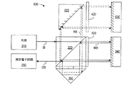
偏光制御式レトロリフレクタの用途は、干渉計に限定されるものではない。図9は、光源910の波長またはスペクトル内容を測定する機能を有する、本発明の一実施形態による測定システム900を示す図である。システム900は、基準レーザー920、偏光ビームスプリッタ930、非偏光ビームスプリッタ940、偏光維持レトロリフレクタ960、965、および検出器システム970を含む。
The application of the polarization-controlled retroreflector is not limited to an interferometer. FIG. 9 is a diagram illustrating a
動作に関し、光源910は、未知の波長またはスペクトル内容のビームを生成し、基準レーザー920は、既知の波長のビームを生成する。偏光ビームスプリッタ930は、PBS930で反射された直線偏光を有する光源910からのビームの一部を、PBS930で透過された直線偏光を有するレーザー920からのビームの一部に結合させるように配置される。結合されたビームは、非偏光ビームスプリッタ940に入射する。非偏光ビームスプリッタ940は、結合ビームの第1の部分(例えば、半分)を偏光維持レトロリフレクタ960に導き、結合ビームの第2の部分を偏光維持レトロリフレクタ965に導く。そして、レトロリフレクタ960および965から戻ってきたビームは、再び非偏光ビームスプリッタ940に入射し、互いに干渉して、出力ビームO1として結合される。
In operation, the
検出器システム970は、出力ビームO1の偏光成分の強度を別個に測定する。測定システム900が偏光を維持している場合、出力ビームO1の1つの偏光成分は、基準レーザー920で生成される既知の波長を有する。レトロリフレクタ960および/またはレトロリフレクタ965を移動させることにより、システム900の2つのアームの光路長差を変化させることができる。レトロリフレクタ960および/または965を移動させると、経路長差が変化して、既知の波長成分との間に建設的干渉と相殺的干渉が交互に発生し、偏光成分の強度は上下することになる。光源910が単色ビームを生成するものである場合、光源910に対応する偏光成分の強度は、経路長間の差の変化に従って同様に上下することになり、その未知の波長は、未知の波長について検出された最大数と、既知の波長について検出された最大数の比から特定することができる。光源910が単色ビームを生成するものでない場合、光源910に対応する偏光成分の強度の測定値は干渉パターンの重ね合わせとなり、光源910からのビームのスペクトル内容は、測定された強度を例えばフーリエ解析その他の技術を用いて分析することにより判定することができる。
The
又、同様に出力ビームO2を分析することにより、出力ビームO1の分析によって得られた測定値を確認したり、改善したりすることができる。 Similarly, by analyzing the output beam O2, the measurement value obtained by analyzing the output beam O1 can be confirmed or improved.
システム900で実施される測定の精度は一般に、異なる光源910および920に対応する偏光成分を弁別および分離する能力によって決まる。本発明の一態様によれば、偏光維持レトロリフレクタ960および965によって偏光成分の混合を低減または回避することにより、正確な測定が実現される。
The accuracy of measurements performed with
本発明は特定の実施形態を参照して説明されているが、その説明は、本発明の応用形態の一例に過ぎず、限定を意図するものとして解釈してはならない。開示した実施形態の特徴の様々な変更および組み合わせも、特許請求の範囲に規定された本発明の範囲内にある。 Although the invention has been described with reference to particular embodiments, the description is only an example of the invention's application and should not be taken as a limitation. Various modifications and combinations of the features of the disclosed embodiments are also within the scope of the invention as defined in the claims.
110 コーナーキューブブロック
160、170 リターデーションプレート
210 光源
220、930 偏光ビームスプリッタ
230 基準反射器
240 測定反射器
320、420 1/4波長板
340、430、830 平面反射器
860 偏光変換レトロリフレクタ
920 基準レーザー
940 非偏光ビームスプリッタ
960、965 偏光維持レトロリフレクタ
970 検出器システム
110
Claims (10)
前記第1の偏光成分と前記第2の偏光成分とを分離するように配置された偏光ビームスプリッタ(220)と、
前記第1の偏光成分と前記第2の偏光成分を再結合させる前に、前記第1の偏光成分を反射させるように配置された第1の偏光操作レトロリフレクタ(230)と、
からなる干渉計システム。 A source (210) of a first input beam comprising a first polarization component and a second polarization component;
A polarizing beam splitter (220) arranged to separate the first polarization component and the second polarization component;
A first polarization manipulating retroreflector (230) arranged to reflect the first polarization component before recombining the first polarization component and the second polarization component;
Interferometer system consisting of
前記第1の平面反射器(340)と前記偏光ビームスプリッタ(220)との間に配置された1/4波長板(320)と
をさらに含み、前記偏光ビームスプリッタ(220)からの前記第2の偏光成分は、前記第2の偏光操作レトロリフレクタ(350)で反射される前と、前記第2の偏光操作レトロリフレクタ(350)で反射された後に、一回づつ前記第1の平面反射器(340)で反射される、請求項2に記載の干渉計システム。 A first planar reflector (340);
A quarter wave plate (320) disposed between the first planar reflector (340) and the polarizing beam splitter (220), the second from the polarizing beam splitter (220). Of the first plane reflector before being reflected by the second polarization manipulation retroreflector (350) and after being reflected by the second polarization manipulation retroreflector (350). The interferometer system of claim 2, wherein the interferometer system is reflected at (340).
前記第1の偏光成分の経路上且つ前記第2の偏光成分の経路上に偏光変換レトロリフレクタ(860)をさらに含む、請求項3に記載の干渉計システム。 A second planar reflector (830) is further included on the path of the first polarization component, and the quarter-wave plate (320) includes the polarization beam splitter (220) and the second planar reflector ( 830), and
The interferometer system of claim 3, further comprising a polarization conversion retroreflector (860) on the path of the first polarization component and on the path of the second polarization component.
前記第1の平面反射器(340)と前記偏光ビームスプリッタ(220)との間に配置された第1の1/4波長板(320)であって、該第1の1/4波長板(320)と前記第1の平面反射器(340)が前記第1の偏光成分の経路上に配置される、第1の1/4波長板(320)と、
第2の平面反射器(430)と、
前記第2の平面反射器(430)と前記偏光ビームスプリッタ(220)との間に配置された第2の1/4波長板(420)であって、該第2の1/4波長板(420)と前記第2の平面反射器(430)が前記第2の偏光成分の経路上に配置される、第2の1/4波長板(420)と、
をさらに含む、請求項1に記載の干渉計システム。 A first planar reflector (340);
A first quarter-wave plate (320) disposed between the first planar reflector (340) and the polarizing beam splitter (220), wherein the first quarter-wave plate (320) 320) and the first planar reflector (340) are disposed on the path of the first polarization component, a first quarter wave plate (320),
A second planar reflector (430);
A second quarter wave plate (420) disposed between the second planar reflector (430) and the polarizing beam splitter (220), the second quarter wave plate ( 420) and the second planar reflector (430) are disposed on the path of the second polarization component; a second quarter wave plate (420);
The interferometer system according to claim 1, further comprising:
反射コーティングが施されたコーナーキューブブロック(110)と、
前記コーナーキューブブロック(110)に入射する入射ビームの経路上に配置された第1のリターデーションプレート(160)と、
前記コーナーキューブブロック(110)からの反射ビームの経路上に配置された台2のリターデーションプレート(170)と、
を含み、前記第1のリターデーションプレート(160)と前記第2のリターデーションプレート(170)のうちの少なくとも一方は、前記反射ビームの所望の偏光を実現するためにの遅軸を設定するために調節可能である、請求項1〜5のうちのいずれか一項に記載の干渉計システム。 The first polarization manipulating retro-reflector (230)
A corner cube block (110) with a reflective coating;
A first retardation plate (160) disposed on a path of an incident beam incident on the corner cube block (110);
A retardation plate (170) of the table 2 disposed on the path of the reflected beam from the corner cube block (110);
And at least one of the first retardation plate (160) and the second retardation plate (170) sets a slow axis for realizing a desired polarization of the reflected beam. The interferometer system according to claim 1, wherein the interferometer system is adjustable.
コーナーキューブブロック(110)と、
前記コーナーキューブブロック(110)に入射する入射ビームの経路上に配置された第1の偏光操作要素(160)であって、前記コーナーキューブブロック(110)が該コーナーキューブブロック(110)からの反射ビームに直線偏光を生成する向きに、前記第1の偏光成分および前記第2の偏光成分の偏光を回転させる、第1の偏光操作要素(160)と、
前記反射ビームの経路上に配置された第2の偏光操作要素(170)と、
を含み、前記第2の偏光操作要素(170)は、前記反射ビームの直線偏光を所望の形態に変換する、請求項1〜5のうちのいずれか一項に記載の干渉計システム。 The first polarization manipulating retro-reflector (230)
Corner cube block (110),
A first polarization manipulation element (160) disposed on a path of an incident beam incident on the corner cube block (110), wherein the corner cube block (110) is reflected from the corner cube block (110); A first polarization manipulating element (160) for rotating the polarization of the first polarization component and the second polarization component in a direction to generate linearly polarized light in the beam;
A second polarization manipulation element (170) disposed on the path of the reflected beam;
The interferometer system according to claim 1, wherein the second polarization manipulating element (170) converts the linear polarization of the reflected beam into a desired form.
基準ビームの発生源(920)と、
前記基準ビームの経路上に配置された偏光ビームスプリッタ(930)であって、第1の偏光を有する前記基準ビームの一部と、前記第1の偏光に対して垂直な第2の偏光を有する前記入力ビームの一部とを含む第1の結合ビームを形成する、偏光ビームスプリッタ(930)と、
前記第1の結合ビームの経路上に配置された非偏光ビームスプリッタ(940)と、
前記非偏光ビームスプリッタ(940)からの第1の出力ビームの経路上に配置された第1の偏光操作レトロリフレクタ(960)と、
前記非偏光ビームスプリッタ(940)からの第2の出力ビームの経路上に配置された第2の偏光操作レトロリフレクタ(965)であって、該第2の偏光操作レトロリフレクタ(965)で反射された後の前記第2の出力ビームを、前記第1の偏光操作レトロリフレクタ(960)で反射された後の前記第1の出力ビームと結合させることにより、第2の結合ビームを形成する、第2の偏光操作レトロリフレクタ(965)と、
前記第2の結合ビームの偏光成分を測定する検出器システム(970)と、
からなるシステム。 A system for analyzing an input beam,
A reference beam source (920);
A polarizing beam splitter (930) disposed on the path of the reference beam, the polarization beam splitter (930) having a portion of the reference beam having a first polarization and a second polarization perpendicular to the first polarization A polarizing beam splitter (930) that forms a first combined beam including a portion of the input beam;
A non-polarizing beam splitter (940) disposed on the path of the first combined beam;
A first polarization manipulating retroreflector (960) disposed on a path of a first output beam from the non-polarizing beam splitter (940);
A second polarization manipulating retroreflector (965) disposed on a path of a second output beam from the non-polarizing beam splitter (940), reflected by the second polarization manipulating retroreflector (965). The second output beam after being combined with the first output beam after being reflected by the first polarization manipulating retroreflector (960) to form a second combined beam, Two polarization-operating retroreflectors (965);
A detector system (970) for measuring the polarization component of the second combined beam;
A system consisting of
反射コーティングが施されたコーナーキューブブロック(110)と、
前記コーナーキューブブロック(110)に入射する入射ビームの経路上に配置された第1のリターデーションプレート(160)と、
前記コーナーキューブブロック(110)からの反射ビームの経路上に配置された台2のリターデーションプレート(170)と、
を含み、前記第1のリターデーションプレート(160)と前記第2のリターデーションプレート(170)のうちの少なくとも一方は、前記反射ビームの所望の偏光を実現するための遅軸を設定するように調節可能である、請求項8に記載のシステム。 At least one of the first polarization manipulating retroreflector (960) and the second polarization manipulating retroreflector (965);
A corner cube block (110) with a reflective coating;
A first retardation plate (160) disposed on a path of an incident beam incident on the corner cube block (110);
A retardation plate (170) of the table 2 disposed on the path of the reflected beam from the corner cube block (110);
And at least one of the first retardation plate (160) and the second retardation plate (170) sets a slow axis for realizing a desired polarization of the reflected beam. The system of claim 8, wherein the system is adjustable.
コーナーキューブブロック(110)と、
前記コーナーキューブブロック(110)に入射する入射ビームの経路上に配置された第1の偏光操作要素(160)であって、前記コーナーキューブブロック(110)が反射ビームに線形偏光を生成する向きに、前記第1の偏光および前記第2の偏光を回転させる第1の偏光操作要素(160)と、
前記コーナーキューブブロック(110)からの前記反射ビームの経路上に配置された第2の偏光操作要素(170)であって、前記反射ビームの直線偏光を所望の形態に変換する、第2の偏光操作要素(170)と、
を含む、請求項8または請求項9に記載のシステム。 At least one of the first polarization manipulating retroreflector (960) and the second polarization manipulating retroreflector (965);
Corner cube block (110),
A first polarization manipulating element (160) disposed on a path of an incident beam incident on the corner cube block (110), wherein the corner cube block (110) is adapted to generate linearly polarized light in a reflected beam; A first polarization manipulation element (160) for rotating the first polarization and the second polarization;
A second polarization manipulating element (170) disposed on the path of the reflected beam from the corner cube block (110), which converts the linearly polarized light of the reflected beam into a desired form. An operating element (170);
10. A system according to claim 8 or claim 9, comprising:
Applications Claiming Priority (1)
| Application Number | Priority Date | Filing Date | Title |
|---|---|---|---|
| US10/856,204 US7193721B2 (en) | 2004-05-28 | 2004-05-28 | Systems using polarization-manipulating retroreflectors |
Publications (2)
| Publication Number | Publication Date |
|---|---|
| JP2005338076A true JP2005338076A (en) | 2005-12-08 |
| JP2005338076A5 JP2005338076A5 (en) | 2008-07-03 |
Family
ID=35424830
Family Applications (1)
| Application Number | Title | Priority Date | Filing Date |
|---|---|---|---|
| JP2005144359A Pending JP2005338076A (en) | 2004-05-28 | 2005-05-17 | System using polarization operation retroreflector |
Country Status (4)
| Country | Link |
|---|---|
| US (1) | US7193721B2 (en) |
| JP (1) | JP2005338076A (en) |
| DE (1) | DE102005009064B4 (en) |
| NL (1) | NL1029115C2 (en) |
Cited By (1)
| Publication number | Priority date | Publication date | Assignee | Title |
|---|---|---|---|---|
| JP2009524064A (en) * | 2006-01-23 | 2009-06-25 | ザイゴ コーポレーション | Interferometer system for monitoring objects |
Families Citing this family (54)
| Publication number | Priority date | Publication date | Assignee | Title |
|---|---|---|---|---|
| US9867530B2 (en) | 2006-08-14 | 2018-01-16 | Volcano Corporation | Telescopic side port catheter device with imaging system and method for accessing side branch occlusions |
| WO2008091961A2 (en) * | 2007-01-23 | 2008-07-31 | Volcano Corporation | Optical coherence tomography implementation |
| US9596993B2 (en) | 2007-07-12 | 2017-03-21 | Volcano Corporation | Automatic calibration systems and methods of use |
| WO2009009799A1 (en) | 2007-07-12 | 2009-01-15 | Volcano Corporation | Catheter for in vivo imaging |
| WO2009009802A1 (en) | 2007-07-12 | 2009-01-15 | Volcano Corporation | Oct-ivus catheter for concurrent luminal imaging |
| US11141063B2 (en) | 2010-12-23 | 2021-10-12 | Philips Image Guided Therapy Corporation | Integrated system architectures and methods of use |
| CN102564613B (en) * | 2010-12-31 | 2014-05-21 | 上海微电子装备有限公司 | Wavelength tracker |
| US11040140B2 (en) | 2010-12-31 | 2021-06-22 | Philips Image Guided Therapy Corporation | Deep vein thrombosis therapeutic methods |
| US9360630B2 (en) | 2011-08-31 | 2016-06-07 | Volcano Corporation | Optical-electrical rotary joint and methods of use |
| US10070827B2 (en) | 2012-10-05 | 2018-09-11 | Volcano Corporation | Automatic image playback |
| US9292918B2 (en) | 2012-10-05 | 2016-03-22 | Volcano Corporation | Methods and systems for transforming luminal images |
| US9286673B2 (en) | 2012-10-05 | 2016-03-15 | Volcano Corporation | Systems for correcting distortions in a medical image and methods of use thereof |
| US11272845B2 (en) | 2012-10-05 | 2022-03-15 | Philips Image Guided Therapy Corporation | System and method for instant and automatic border detection |
| US9307926B2 (en) | 2012-10-05 | 2016-04-12 | Volcano Corporation | Automatic stent detection |
| US10568586B2 (en) | 2012-10-05 | 2020-02-25 | Volcano Corporation | Systems for indicating parameters in an imaging data set and methods of use |
| US9858668B2 (en) | 2012-10-05 | 2018-01-02 | Volcano Corporation | Guidewire artifact removal in images |
| US9367965B2 (en) | 2012-10-05 | 2016-06-14 | Volcano Corporation | Systems and methods for generating images of tissue |
| US9324141B2 (en) | 2012-10-05 | 2016-04-26 | Volcano Corporation | Removal of A-scan streaking artifact |
| JP2015532536A (en) | 2012-10-05 | 2015-11-09 | デイビッド ウェルフォード, | System and method for amplifying light |
| US9840734B2 (en) | 2012-10-22 | 2017-12-12 | Raindance Technologies, Inc. | Methods for analyzing DNA |
| EP2931132B1 (en) | 2012-12-13 | 2023-07-05 | Philips Image Guided Therapy Corporation | System for targeted cannulation |
| EP2934310A4 (en) | 2012-12-20 | 2016-10-12 | Nathaniel J Kemp | Optical coherence tomography system that is reconfigurable between different imaging modes |
| US11406498B2 (en) | 2012-12-20 | 2022-08-09 | Philips Image Guided Therapy Corporation | Implant delivery system and implants |
| CA2895770A1 (en) | 2012-12-20 | 2014-07-24 | Jeremy Stigall | Locating intravascular images |
| US10939826B2 (en) | 2012-12-20 | 2021-03-09 | Philips Image Guided Therapy Corporation | Aspirating and removing biological material |
| WO2014099899A1 (en) | 2012-12-20 | 2014-06-26 | Jeremy Stigall | Smooth transition catheters |
| US10942022B2 (en) | 2012-12-20 | 2021-03-09 | Philips Image Guided Therapy Corporation | Manual calibration of imaging system |
| US10413317B2 (en) | 2012-12-21 | 2019-09-17 | Volcano Corporation | System and method for catheter steering and operation |
| WO2014100606A1 (en) | 2012-12-21 | 2014-06-26 | Meyer, Douglas | Rotational ultrasound imaging catheter with extended catheter body telescope |
| US9612105B2 (en) | 2012-12-21 | 2017-04-04 | Volcano Corporation | Polarization sensitive optical coherence tomography system |
| CA2896006A1 (en) | 2012-12-21 | 2014-06-26 | David Welford | Systems and methods for narrowing a wavelength emission of light |
| EP2936426B1 (en) | 2012-12-21 | 2021-10-13 | Jason Spencer | System and method for graphical processing of medical data |
| US10058284B2 (en) | 2012-12-21 | 2018-08-28 | Volcano Corporation | Simultaneous imaging, monitoring, and therapy |
| WO2014100162A1 (en) | 2012-12-21 | 2014-06-26 | Kemp Nathaniel J | Power-efficient optical buffering using optical switch |
| EP2934280B1 (en) | 2012-12-21 | 2022-10-19 | Mai, Jerome | Ultrasound imaging with variable line density |
| EP2934323A4 (en) | 2012-12-21 | 2016-08-17 | Andrew Hancock | System and method for multipath processing of image signals |
| US9486143B2 (en) | 2012-12-21 | 2016-11-08 | Volcano Corporation | Intravascular forward imaging device |
| US10226597B2 (en) | 2013-03-07 | 2019-03-12 | Volcano Corporation | Guidewire with centering mechanism |
| US9770172B2 (en) | 2013-03-07 | 2017-09-26 | Volcano Corporation | Multimodal segmentation in intravascular images |
| US11154313B2 (en) | 2013-03-12 | 2021-10-26 | The Volcano Corporation | Vibrating guidewire torquer and methods of use |
| EP2967391A4 (en) | 2013-03-12 | 2016-11-02 | Donna Collins | Systems and methods for diagnosing coronary microvascular disease |
| US10758207B2 (en) | 2013-03-13 | 2020-09-01 | Philips Image Guided Therapy Corporation | Systems and methods for producing an image from a rotational intravascular ultrasound device |
| US9301687B2 (en) | 2013-03-13 | 2016-04-05 | Volcano Corporation | System and method for OCT depth calibration |
| US11026591B2 (en) | 2013-03-13 | 2021-06-08 | Philips Image Guided Therapy Corporation | Intravascular pressure sensor calibration |
| US20160030151A1 (en) | 2013-03-14 | 2016-02-04 | Volcano Corporation | Filters with echogenic characteristics |
| US10292677B2 (en) | 2013-03-14 | 2019-05-21 | Volcano Corporation | Endoluminal filter having enhanced echogenic properties |
| US10219887B2 (en) | 2013-03-14 | 2019-03-05 | Volcano Corporation | Filters with echogenic characteristics |
| US9874435B2 (en) * | 2014-05-22 | 2018-01-23 | Samsung Electronics Co., Ltd. | Measuring system and measuring method |
| TW201831925A (en) * | 2017-02-20 | 2018-09-01 | 美商3M新設資產公司 | Retroreflecting article including retarder |
| US10041781B1 (en) * | 2017-06-14 | 2018-08-07 | Southern Research Institute | Multi-pass optical system to improve resolution of interferometers |
| US20190113329A1 (en) | 2017-10-12 | 2019-04-18 | Keysight Technologies, Inc. | Systems and methods for cyclic error correction in a heterodyne interferometer |
| CN113740946A (en) * | 2021-08-30 | 2021-12-03 | 中国科学院上海应用物理研究所 | Polarization maintaining reflector group |
| CN114114701B (en) * | 2021-11-16 | 2023-09-12 | 中国科学院上海技术物理研究所 | Method and device for realizing polarization degradation through pyramid prism and beam splitter prism |
| CN117559219A (en) * | 2022-08-05 | 2024-02-13 | 青岛海信宽带多媒体技术有限公司 | Laser and optical module |
Citations (6)
| Publication number | Priority date | Publication date | Assignee | Title |
|---|---|---|---|---|
| JPS60233502A (en) * | 1984-04-27 | 1985-11-20 | Yokogawa Hewlett Packard Ltd | Interferometer |
| JPS63228003A (en) * | 1987-03-02 | 1988-09-22 | Yokogawa Hewlett Packard Ltd | Interferometer |
| JPH01206283A (en) * | 1988-02-13 | 1989-08-18 | Brother Ind Ltd | Optical heterodyne measuring apparatus |
| US4883357A (en) * | 1989-03-01 | 1989-11-28 | Zygo Corporation | Dual high stability interferometer |
| JPH0587519A (en) * | 1991-09-25 | 1993-04-06 | Hide Hosoe | Differential type interference prism |
| US20020001087A1 (en) * | 2000-05-17 | 2002-01-03 | Hill Henry Allen | Apparatus and method for interferometric measurements of angular orientation and distance to a plane mirror object |
Family Cites Families (11)
| Publication number | Priority date | Publication date | Assignee | Title |
|---|---|---|---|---|
| US4930894A (en) * | 1984-04-27 | 1990-06-05 | Hewlett-Packard Company | Minimum deadpath interferometer and dilatometer |
| US4693605A (en) | 1985-12-19 | 1987-09-15 | Zygo Corporation | Differential plane mirror interferometer |
| US4714339B2 (en) * | 1986-02-28 | 2000-05-23 | Us Commerce | Three and five axis laser tracking systems |
| JP2808136B2 (en) * | 1989-06-07 | 1998-10-08 | キヤノン株式会社 | Length measuring method and device |
| AT397307B (en) * | 1990-03-02 | 1994-03-25 | Tabarelli Werner | INTERFEROMETERS IN PARTICULAR FOR LENGTH MEASUREMENT |
| US5408318A (en) * | 1993-08-02 | 1995-04-18 | Nearfield Systems Incorporated | Wide range straightness measuring stem using a polarized multiplexed interferometer and centered shift measurement of beam polarization components |
| US6198574B1 (en) | 1999-08-27 | 2001-03-06 | Zygo Corporation | Polarization preserving optical systems |
| US6201609B1 (en) | 1999-08-27 | 2001-03-13 | Zygo Corporation | Interferometers utilizing polarization preserving optical systems |
| US6462827B1 (en) * | 2001-04-30 | 2002-10-08 | Chromaplex, Inc. | Phase-based wavelength measurement apparatus |
| US7224466B2 (en) * | 2003-02-05 | 2007-05-29 | Agilent Technologies, Inc. | Compact multi-axis interferometer |
| US7075655B2 (en) * | 2003-09-23 | 2006-07-11 | Agilent Technologies, Inc. | Alignment self check for a wavelength meter |
-
2004
- 2004-05-28 US US10/856,204 patent/US7193721B2/en not_active Expired - Fee Related
-
2005
- 2005-02-28 DE DE102005009064A patent/DE102005009064B4/en not_active Expired - Fee Related
- 2005-05-17 JP JP2005144359A patent/JP2005338076A/en active Pending
- 2005-05-24 NL NL1029115A patent/NL1029115C2/en not_active IP Right Cessation
Patent Citations (6)
| Publication number | Priority date | Publication date | Assignee | Title |
|---|---|---|---|---|
| JPS60233502A (en) * | 1984-04-27 | 1985-11-20 | Yokogawa Hewlett Packard Ltd | Interferometer |
| JPS63228003A (en) * | 1987-03-02 | 1988-09-22 | Yokogawa Hewlett Packard Ltd | Interferometer |
| JPH01206283A (en) * | 1988-02-13 | 1989-08-18 | Brother Ind Ltd | Optical heterodyne measuring apparatus |
| US4883357A (en) * | 1989-03-01 | 1989-11-28 | Zygo Corporation | Dual high stability interferometer |
| JPH0587519A (en) * | 1991-09-25 | 1993-04-06 | Hide Hosoe | Differential type interference prism |
| US20020001087A1 (en) * | 2000-05-17 | 2002-01-03 | Hill Henry Allen | Apparatus and method for interferometric measurements of angular orientation and distance to a plane mirror object |
Cited By (1)
| Publication number | Priority date | Publication date | Assignee | Title |
|---|---|---|---|---|
| JP2009524064A (en) * | 2006-01-23 | 2009-06-25 | ザイゴ コーポレーション | Interferometer system for monitoring objects |
Also Published As
| Publication number | Publication date |
|---|---|
| US7193721B2 (en) | 2007-03-20 |
| US20050264823A1 (en) | 2005-12-01 |
| DE102005009064B4 (en) | 2008-06-26 |
| NL1029115A1 (en) | 2005-11-30 |
| NL1029115C2 (en) | 2007-06-01 |
| DE102005009064A1 (en) | 2005-12-22 |
Similar Documents
| Publication | Publication Date | Title |
|---|---|---|
| JP2005338076A (en) | System using polarization operation retroreflector | |
| US6897962B2 (en) | Interferometer using beam re-tracing to eliminate beam walk-off | |
| US4859066A (en) | Linear and angular displacement measuring interferometer | |
| US5847828A (en) | Michelson interferometer using matched wedge-shaped beam splitter and compensator | |
| US4883357A (en) | Dual high stability interferometer | |
| US4881815A (en) | Linear and angular displacement measuring interferometer | |
| US20070041022A1 (en) | Interferometer for measuring perpendicular translations | |
| US4717250A (en) | Angle measuring interferometer | |
| WO2013013346A1 (en) | Interferometer with four axes and 4 subdivisions | |
| US20040150831A1 (en) | Compact multi-axis interferometer | |
| US7705994B2 (en) | Monolithic displacement measuring interferometer with spatially separated but substantially equivalent optical pathways and optional dual beam outputs | |
| WO2001088468A1 (en) | Interferometric apparatus and method | |
| WO2013013345A1 (en) | Interferometer with six axes and 4 subdivisions | |
| EP1751491B1 (en) | Polarising interferometer with removal or separation of error beam caused by leakage of polarised light | |
| US4807997A (en) | Angular displacement measuring interferometer | |
| US5028137A (en) | Angular displacement measuring interferometer | |
| US20060017933A1 (en) | Heterodyne laser interferometer with porro prisms for measuring stage displacement | |
| US20090135430A1 (en) | Systems and Methods for Reducing Nonlinearity in an Interferometer | |
| JPS58160848A (en) | Photointerferometer | |
| JPH11183116A (en) | Method and device for light wave interference measurement | |
| EP0461773A2 (en) | Linear pitch, and yaw displacement measuring interferometer | |
| JPH11125503A (en) | Heterodyne interferometer | |
| JP4028428B2 (en) | Compact beam retrace optics for eliminating beam walk-off in interferometers | |
| JPS59136604A (en) | Multiple optical path laser interferometer | |
| JPH04155260A (en) | Rotational speed measuring apparatus |
Legal Events
| Date | Code | Title | Description |
|---|---|---|---|
| A521 | Written amendment |
Free format text: JAPANESE INTERMEDIATE CODE: A523 Effective date: 20080519 |
|
| A621 | Written request for application examination |
Free format text: JAPANESE INTERMEDIATE CODE: A621 Effective date: 20080519 |
|
| A131 | Notification of reasons for refusal |
Free format text: JAPANESE INTERMEDIATE CODE: A131 Effective date: 20100907 |
|
| A02 | Decision of refusal |
Free format text: JAPANESE INTERMEDIATE CODE: A02 Effective date: 20110215 |