JP2005334871A - Production method for porous material and apparatus therefor - Google Patents
Production method for porous material and apparatus therefor Download PDFInfo
- Publication number
- JP2005334871A JP2005334871A JP2005126791A JP2005126791A JP2005334871A JP 2005334871 A JP2005334871 A JP 2005334871A JP 2005126791 A JP2005126791 A JP 2005126791A JP 2005126791 A JP2005126791 A JP 2005126791A JP 2005334871 A JP2005334871 A JP 2005334871A
- Authority
- JP
- Japan
- Prior art keywords
- solvent
- pressure
- porous body
- unit
- producing
- Prior art date
- Legal status (The legal status is an assumption and is not a legal conclusion. Google has not performed a legal analysis and makes no representation as to the accuracy of the status listed.)
- Granted
Links
Images


Abstract
Description
本発明は、エアロゲル等の多孔体の製造方法およびその為の装置に関するものであり、特に乾燥工程において多孔体にクラック等が発生するのを防止しつつ多孔体を製造することのできる方法、およびその為の有用な装置に関するものである。 The present invention relates to a method for producing a porous body such as airgel and an apparatus therefor, and in particular, a method capable of producing a porous body while preventing cracks and the like from being generated in the porous body in the drying step, and The present invention relates to a useful device for this purpose.
光透過性または光半透過性の無機多孔体としては、例えばアルコキシシランを加水分解、縮重合して得られるゲル状化合物(湿潤ゲル)を生成した後、このゲル状化合物を生成するために用いられた溶媒を除去して乾燥して得られるエアロゲルが知られている。このエアロゲルは、軽量で且つ優れた断熱性を有することから、様々な分野で有用な断熱材の素材として注目されている。 As the light-transmitting or light-semi-transmitting inorganic porous material, for example, a gel-like compound (wet gel) obtained by hydrolysis and condensation polymerization of alkoxysilane is generated, and then used to generate this gel-like compound. An airgel obtained by removing the obtained solvent and drying is known. Since this airgel is lightweight and has excellent heat insulating properties, it has attracted attention as a material for heat insulating materials useful in various fields.
エアロゲルを製造するに際して、上記ゲル状化合物(湿潤ゲル)を生成する際に用いられた溶媒をゲル状化合物から効果的に除去して乾燥ゲルを得る必要がある。しかしながら、湿潤ゲルをそのままの状態で乾燥すれば、ゲル状化合の構造が破壊され、形状を保ったまま乾燥することができない。これは、気体などの界面で発生する界面張力に起因する応力が原因であると考えられている。 In producing an airgel, it is necessary to effectively remove the solvent used in producing the gel compound (wet gel) from the gel compound to obtain a dry gel. However, if the wet gel is dried as it is, the structure of the gel compound is destroyed and cannot be dried while maintaining the shape. This is considered to be caused by stress caused by interfacial tension generated at the interface of gas or the like.
こうした構造の破壊を防止する手段は、代表的なものとして超臨界条件下で乾燥する方法が知られている(例えば、非特許文献1)。この方法は、雰囲気を超臨界状態にすれば気液の区別が無くなり、界面における界面張力の発生が理論上無くなることを原理とするものである。 As a typical means for preventing such structural destruction, a method of drying under supercritical conditions is known (for example, Non-Patent Document 1). This method is based on the principle that if the atmosphere is brought into a supercritical state, gas-liquid distinction is eliminated and generation of interfacial tension at the interface is theoretically eliminated.
上記の原理を応用した技術として、例えば特許文献1に示すような技術も提案されている。この技術では、ゲル状化合物中に含まれる溶媒(例えば、アルコール)を超臨界の二酸化炭素で置換しつつ乾燥する方法である。この方法によれば、二酸化炭素における臨界温度・圧力が比較的低いことから、比較的容易に、また安価に超臨界状態を実現できる。 As a technique applying the above principle, for example, a technique as shown in Patent Document 1 has been proposed. This technique is a method of drying while replacing a solvent (for example, alcohol) contained in a gel compound with supercritical carbon dioxide. According to this method, since the critical temperature and pressure in carbon dioxide are relatively low, a supercritical state can be realized relatively easily and inexpensively.
しかしながら、超臨界状態の二酸化炭素を供給するときに、ゲル周辺の溶媒の置換速度が速過ぎると、ゲル内の急速な濃度変化等に起因する湿潤ゲル内の界面張力等の発生、溶媒の拡散や膨張に伴う応力が大きくなり、エアロゲルに亀裂が生じるという問題が依然と残っている。このため、長時間をかけて超臨界状態の二酸化炭素を供給するなどの方法が採られている。 However, when supplying carbon dioxide in the supercritical state, if the displacement rate of the solvent around the gel is too fast, the generation of interfacial tension in the wet gel due to rapid concentration change in the gel, diffusion of the solvent, etc. Still, there remains a problem that the stress associated with expansion increases and the airgel cracks. For this reason, a method of supplying carbon dioxide in a supercritical state over a long period of time has been adopted.
一方、亀裂の発生を防止するという観点から、特許文献2のような技術も提案されている。この技術では、溶媒置換の後に、溶媒の沸点以上の温度で高圧容器内を保持することによって、雰囲気中に残存する溶媒が液化することを防ぎ、これによって界面の発生を防ぎ、ゲル状化合物の構造が破壊することを防止するものである。しかしながら、こうした処理を施しても、それほど操業効率が向上するとは言えず、また置換速度が速過ぎると、クラック発生という問題は、依然として存在する。
本発明はこうした状況の下でなされたものであって、その目的は、乾燥工程での亀裂の発生や多孔体破壊などを防止しつつ、多孔体を効率良く製造することのできる方法、およびこうした方法を実施するための有用な製造装置を提供することにある。 The present invention has been made under such circumstances, and an object of the present invention is to provide a method capable of efficiently producing a porous body while preventing the occurrence of cracks in the drying process and the destruction of the porous body, and the like. The object is to provide a useful manufacturing apparatus for carrying out the method.
上記課題を解決することのできた本発明とは、第一の液体溶媒を含有する湿潤体中の該第一の溶媒を、高圧状態の第二の溶媒で置換しつつ乾燥して多孔体を製造する方法において、前記第一の溶媒と同一または同種の溶媒と、前記第二の溶媒との混合溶液を供給しつつ操業する点に要旨を有するものである。 The present invention was able to solve the above-mentioned problems, and produced a porous body by drying while replacing the first solvent in the wet body containing the first liquid solvent with the second solvent in a high-pressure state. In this method, the present invention has a gist in that it operates while supplying a mixed solution of the same or the same kind of solvent as the first solvent and the second solvent.
この方法においては、前記混合溶媒中の各溶媒の混合比率を変化させ、前記第二の溶媒の混合比率を徐々に大きくして供給することが好ましい。前記第二の溶媒の混合比率を徐々に大きくするに当っては、該第二の溶媒の混合比率の増加割合自体を徐々に大きくすることが好ましい。 In this method, it is preferable to supply by gradually increasing the mixing ratio of the second solvent by changing the mixing ratio of each solvent in the mixed solvent. In gradually increasing the mixing ratio of the second solvent, it is preferable to gradually increase the increase ratio itself of the mixing ratio of the second solvent.
本発明方法においては、前記混合溶媒の圧力を徐々に小さくすることが好ましい。本発明方法で対象とする多孔体としては、エアロゲルが代表的なものとして挙げられる。また、用いる溶媒としては、前記第一の溶媒がアルコールであり、前記第二の溶媒が二酸化炭素の組み合わせが好ましい。 In the method of the present invention, it is preferable to gradually reduce the pressure of the mixed solvent. A typical example of the porous body targeted by the method of the present invention is airgel. Moreover, as a solvent to be used, the first solvent is preferably an alcohol and the second solvent is preferably a combination of carbon dioxide.
一方、上記目的を達成し得た本発明の製造装置とは、第一の液体溶媒を含有する湿潤体中の該第一の溶媒を、高圧状態の第二の溶媒で置換しつつ乾燥処理して多孔体を製造する様に構成された多孔体の製造装置において、
前記第一の溶媒と同一または同種の溶媒を高圧状態にして供給する第一溶媒高圧供給部と、
前記第二の溶媒を高圧状態にして供給する第二溶媒高圧供給部と、
前記第一の溶媒と第二の溶媒を高圧状態で混合する高圧混合部と、
前記高圧混合部から供給された高圧混合溶媒を、処理槽内に設置された多孔体素材と接触させて処理する多孔体処理部と、
を備えた点に要旨を有する多孔体の製造装置である。
On the other hand, the production apparatus of the present invention capable of achieving the above object is a drying process while replacing the first solvent in the wet body containing the first liquid solvent with the second solvent in a high-pressure state. In the porous body manufacturing apparatus configured to manufacture the porous body,
A first solvent high pressure supply section for supplying the same or the same kind of solvent as the first solvent in a high pressure state;
A second solvent high pressure supply section for supplying the second solvent in a high pressure state;
A high pressure mixing section for mixing the first solvent and the second solvent in a high pressure state;
A high-pressure mixed solvent supplied from the high-pressure mixing section, and a porous body processing section for processing by bringing the high-pressure mixed solvent into contact with a porous material installed in a processing tank;
It is the manufacturing apparatus of the porous body which has a summary in the point provided with.
上記本発明の装置においては、前記第一の溶媒と同一または同種の溶媒の供給量と前記第二の溶媒の供給量の比率を変化させつつ操業するように構成することが好ましい。また、多孔体処理後の混合溶媒から、前記第一の溶媒と同一または同種の溶媒を分離する第一溶媒分離部を備えていることが好ましい。また、前記第一溶媒分離部で分離された前記第一の溶媒と同一または同種の溶媒を蓄える第一溶媒貯蔵部を備え、該第一溶媒貯蔵部からの前記第一の溶媒と同一または同種の溶媒を、前記第一溶媒高圧供給部に循環して再利用するように構成することも好ましい。更に、前記多孔体処理部以降に減圧手段を備えると共に、前記多孔体処理部に供給される高圧混合溶媒の圧力を検出する圧力検出手段を該多孔体処理部に備え、前記圧力検出手段で検出された信号に基づき、前記減圧手段を制御して、前記高圧混合溶媒の圧力を徐々に小さくしつつ操業するように構成することも好ましい。 The apparatus of the present invention is preferably configured to operate while changing the ratio of the supply amount of the same or the same solvent as the first solvent and the supply amount of the second solvent. Moreover, it is preferable to provide the 1st solvent separation part which isolate | separates the same or same kind of solvent as said 1st solvent from the mixed solvent after a porous body process. The first solvent storage unit stores the same or the same type of solvent as the first solvent separated by the first solvent separation unit, and is the same or the same type as the first solvent from the first solvent storage unit. It is also preferable that the solvent is recycled to the first solvent high-pressure supply unit and reused. Further, a pressure reducing means is provided after the porous body processing section, and a pressure detecting means for detecting the pressure of the high-pressure mixed solvent supplied to the porous body processing section is provided in the porous body processing section, and is detected by the pressure detecting means. It is also preferable that the pressure reducing means is controlled based on the signal so as to operate while gradually decreasing the pressure of the high pressure mixed solvent.
本発明に係る製造装置の他の構成としては、第一の液体溶媒を含有する湿潤体中の該第一の溶媒を、高圧状態の第二の溶媒で置換しつつ乾燥処理して多孔体を製造する様に構成された多孔体の製造装置において、
前記第一の溶媒を含有する前記湿潤体が設置されて処理される多孔体処理部と、
多孔体処理部から排出された高圧溶媒を循環供給する高圧溶媒循環部と、
前記第二の溶媒を高圧状態にして供給する第二溶媒高圧供給部と、
前記高圧溶媒循環部からの溶媒と前記第二溶媒供給部からの前記第二の溶媒を高圧状態で混合し、その後、前記多孔体処理部に混合溶媒を供給する高圧混合部と、
を備えたものが挙げられ、こうした構成の装置であっても本発明の上記目的が達成される。
As another configuration of the production apparatus according to the present invention, a porous body is obtained by performing a drying treatment while replacing the first solvent in the wet body containing the first liquid solvent with the second solvent in a high-pressure state. In the porous body manufacturing apparatus configured to manufacture,
A porous body processing section in which the wet body containing the first solvent is installed and processed;
A high-pressure solvent circulation unit that circulates and supplies the high-pressure solvent discharged from the porous body processing unit;
A second solvent high pressure supply section for supplying the second solvent in a high pressure state;
A high-pressure mixing unit that mixes the solvent from the high-pressure solvent circulation unit and the second solvent from the second solvent supply unit in a high-pressure state, and then supplies a mixed solvent to the porous body processing unit;
The above object of the present invention can be achieved even with an apparatus having such a configuration.
この装置においては、前記第二溶媒供給部から前記第二の溶媒の供給量を制御することによって、前記溶媒混合部から前記多孔体処理部に供給される溶媒中における該第二の溶媒の混合比率を変化させつつ操業するように構成することが好ましい。また、前記多孔体処理部での多孔体処理後の混合溶媒の一部から、前記第一の溶媒を分離する第一溶媒分離部を備えていることが好ましい。また、前記第一溶媒分離部で分離された第一溶媒を蓄える第一溶媒貯蔵部を備え、該第一溶媒貯蔵部からの前記第一の溶媒を多孔体処理部に循環供給して再利用するように構成することも好ましい。更に、上記装置と同様に、前記多孔体処理部以降に減圧手段を備えると共に、前記多孔体処理部に供給される高圧混合溶媒の圧力を検出する圧力検出手段を該多孔体処理部に備え、前記圧力検出手段で検出された信号に基づき、前記減圧手段を制御して、前記高圧混合溶媒の圧力を徐々に小さくしつつ操業するように構成することも好ましい。 In this apparatus, the mixing of the second solvent in the solvent supplied from the solvent mixing unit to the porous body processing unit is controlled by controlling the supply amount of the second solvent from the second solvent supplying unit. It is preferable that the operation is performed while changing the ratio. Moreover, it is preferable to provide the 1st solvent separation part which isolate | separates said 1st solvent from a part of mixed solvent after the porous body process in the said porous body process part. A first solvent storage unit for storing the first solvent separated by the first solvent separation unit; and recycling the first solvent from the first solvent storage unit to the porous body processing unit It is also preferable to configure so as to. Further, similarly to the above apparatus, the porous body processing section includes a pressure reducing means after the porous body processing section, and pressure detecting means for detecting the pressure of the high-pressure mixed solvent supplied to the porous body processing section. It is also preferable that the pressure reducing means is controlled based on the signal detected by the pressure detecting means so that the operation is performed while gradually reducing the pressure of the high pressure mixed solvent.
本発明では、溶媒を置換しつつ湿潤体(湿潤ゲル)を乾燥して多孔体を製造するに際して、置換用の溶媒だけを供給するのではなく、湿潤体中に含まれている溶媒と同一または同種の溶媒と置換用溶媒を混合した混合溶媒を供給するようにしたので、両溶媒間に二相(液/液或は気/液)界面が生じたり、置換速度が速過ぎることに起因する湿潤ゲル内に発生する応力を緩和することができ、亀裂の発生やゲル状化合物の構造の破壊を防止しつつ、効率良く多孔体を製造することができる。 In the present invention, when the porous body is produced by drying the wet body (wet gel) while replacing the solvent, the solvent is not the same as the solvent contained in the wet body, Due to supplying a mixed solvent in which the same type of solvent and substitution solvent are mixed, a two-phase (liquid / liquid or gas / liquid) interface is formed between the two solvents, or the substitution speed is too high. The stress generated in the wet gel can be relaxed, and a porous body can be produced efficiently while preventing the generation of cracks and the destruction of the structure of the gel compound.
本発明者らは、上記目的を達成する為に様々な角度から検討した。その結果、溶媒を置換しつつ湿潤体(湿潤ゲル)を乾燥して多孔体を製造するに際して、湿潤体中に含まれている溶媒と同一または同種の溶媒と置換用溶媒を混合した混合溶媒を供給するようにすれば、上記目的が見事に達成されることを見出し、本発明を完成した。尚、ここで言う「同種」とは、互いに相溶であることを言い、例えばアルコールと水、エタノールと水、エタノールとメタノール等の組み合わせが例として挙げられる。また、本発明で言う「循環して再利用」、或いは「循環供給して再利用」には、全部を循環する場合だけでなく、一部のみを循環する場合も含まれる。 The present inventors have studied from various angles in order to achieve the above object. As a result, when producing a porous body by drying the wet body (wet gel) while substituting the solvent, a mixed solvent in which the same or the same type of solvent as the solvent contained in the wet body and a replacement solvent is mixed is used. As a result, the present inventors have found that the above object can be achieved brilliantly, thereby completing the present invention. In addition, "same kind" said here is mutually compatible, for example, the combination of alcohol and water, ethanol and water, ethanol and methanol etc. is mentioned as an example. Further, “circulation and reuse” or “circulation supply and reuse” as used in the present invention includes not only the case where all are circulated but also the case where only a part is circulated.
乾燥工程において置換用の溶媒だけを高圧状態(特に超臨界状態)で供給すると、両溶媒間に二相界面が生じたり、置換速度が速くなり過ぎることに起因し、湿潤ゲルに応力が発生することになる。これに対して、上記のような混合溶媒の形態で置換用溶媒を供給することによって、多孔体内の溶媒と外部から供給される溶媒の濃度差を任意に制御でき、湿潤体に負荷する応力が極力低減できるのである。 If only the solvent for replacement is supplied in a high-pressure state (especially in the supercritical state) in the drying process, a stress occurs in the wet gel due to the formation of a two-phase interface between the two solvents or the excessive replacement speed. It will be. In contrast, by supplying the replacement solvent in the form of the mixed solvent as described above, the concentration difference between the solvent in the porous body and the solvent supplied from the outside can be arbitrarily controlled, and the stress applied to the wet body is reduced. It can be reduced as much as possible.
本発明では、置換用溶媒を上記のような混合溶媒の形態で供給するだけでも、その効果が発揮されるのであるが、前記混合溶媒中の各溶媒の混合比率を変化させ、第二の溶媒に混合比率を徐々に大きくして供給することが好ましい。尚、ここで言う「第二の溶媒の混合比率が徐々に大きくなるように供給する」とは、混合溶媒を供給する過程を経るに従って、第二の溶媒の混合比率が大きくなるように供給するという意味である。またその意味するところは、第二の溶媒の混合比率が連続的に滑らかに大きくなるように混合溶媒を供給することに限定されるものではなく、その混合比率が段階的に大きくなるように、混合溶媒を供給するものであっても良い。こうした構成を採用することによって、多孔体内外の濃度差をできるだけ抑えつつ、速やかに溶媒置換を図ることができることになる。 In the present invention, even if the replacement solvent is supplied in the form of the mixed solvent as described above, the effect is exhibited. However, the mixing ratio of each solvent in the mixed solvent is changed, and the second solvent is used. It is preferable to gradually increase the mixing ratio. Here, “suppliing the mixing ratio of the second solvent so as to gradually increase” means supplying the mixing ratio of the second solvent to increase as the mixed solvent is supplied. It means that. Further, the meaning is not limited to supplying the mixed solvent so that the mixing ratio of the second solvent continuously increases smoothly, so that the mixing ratio increases stepwise. A mixed solvent may be supplied. By adopting such a configuration, it is possible to promptly replace the solvent while suppressing the difference in concentration inside and outside the porous body as much as possible.
本発明で対象とする多孔体としては、シリカエアロゲルが挙げられるが、これに限らず、例えば金属酸化物エアロゲル/多孔体(例えば、単一酸化物触媒、複合酸化物触媒、触媒単体等の用途で、TiO2,Al2O3,MgO,SiO2―TiO2,SiO2−Al2O3,Pd−Al2O3,Ni−SiO2,ゼオライト,BaAl12O19,TiCl4−Al2O3等)、ポリマーエアロゲル(例えば、レゾルシノールホルムアルデヒド樹脂、Cuを含むコポリマー等)、粘土層間架橋多孔体等の多孔体、或いは、通常の乾燥では毛管力によって破壊してしまう脆い物質(バイオポリマーの一種であるフミン酸乾燥体等)、凝集してしまう物質(Y−Ba−Cu−O系複酸化物微粉末等)、等を対象とすることができる。こうした多孔体においても、乾燥工程において同様な問題が生じ、本発明を適用することによって、こうした問題が解消できる。
Examples of the porous body to be used in the present invention include silica aerogel, but are not limited thereto. For example, metal oxide airgel / porous body (for example, a single oxide catalyst, a composite oxide catalyst, a catalyst simple substance, etc.) in, TiO 2, Al 2 O 3 , MgO, SiO 2 -TiO 2, SiO 2 -Al 2
本発明を実施するに際して、湿潤体(例えば、湿潤ゲル)中に含まれる第一の溶媒としては、多孔体の湿潤ゲルの製造に使用される溶媒が該当し、一般的には、アルコール類が使用される例が多い。また、このアルコールとしては、メタノール、エタノール、イソプロパノール、ブタノール等のいずれも使用でき、特に限定されない。 In practicing the present invention, the first solvent contained in the wet body (for example, a wet gel) corresponds to a solvent used for the production of a porous wet gel. Generally, alcohols are used. There are many examples used. Moreover, as this alcohol, any of methanol, ethanol, isopropanol, butanol, etc. can be used, and it is not specifically limited.
またこの第一の溶媒は、例えばエアロゲルを製造する段階で含まれるアルコールを想定したものであるが、エアロゲルを製造する段階で含まれるアルコールを、一旦別の溶媒で置換して製造段階で含まれる触媒等を除去した段階の溶媒、或いは、エアロゲルを疎水化処理した段階の触媒、更に、超臨界二酸化炭素への溶解性が高い溶媒に置換した段階での溶媒、例えば、アセトン、ヘキサン等の有機溶媒であっても良い。 In addition, the first solvent is assumed to be an alcohol contained in the step of producing an airgel, for example, but the alcohol contained in the step of producing an airgel is temporarily substituted with another solvent and included in the production step. Solvent at the stage where the catalyst, etc. is removed, or the catalyst at the stage where the airgel has been hydrophobized, and the solvent at the stage where the solvent is replaced with a solvent having high solubility in supercritical carbon dioxide, such as organic solvents such as acetone and hexane It may be a solvent.
一方、本発明で第一の溶媒と置換する為に用いる第二の溶媒としては、容易に高圧状態(特に、超臨界状態)を達成できるものであれば、特に限定するものではなく、例えば、二酸化炭素、亜酸化窒素、プロパン、アンモニア等が挙げられる。このうち、臨界温度・臨界圧力が比較的低い、安全な流体、安価という観点から、二酸化炭素が好ましいものとして推奨される。特に、二酸化炭素では、超臨界状態のアルコールを使用する場合と比較して、安価に処理を行うことができるという利点がある。 On the other hand, the second solvent used to replace the first solvent in the present invention is not particularly limited as long as it can easily achieve a high-pressure state (particularly a supercritical state). Examples include carbon dioxide, nitrous oxide, propane, and ammonia. Among these, carbon dioxide is recommended as a preferable one from the viewpoint of a relatively low critical temperature and critical pressure, a safe fluid, and low cost. In particular, carbon dioxide has an advantage that the treatment can be performed at a low cost as compared with the case of using alcohol in a supercritical state.
上記第二の溶媒の供給は、第一の溶媒と第二の溶媒が二相状態(液/液或いは気液共存相)を形成しない二成分系の臨界状態以上の条件であれば良く、第一の溶媒、或いは、第二の溶媒の臨界状態以上であることを必須とするものではない。また、混合された段階での第一の溶媒は、第一の溶媒の臨界状態以上、また、第二の溶媒の臨界状態以上であることを必須とするものではないが、ゲル内の置換を効率的に行うためには、第二の溶媒の臨界条件以上の圧力・温度の方がより好ましい。尚、本発明での「臨界状態以上」とは、「超臨界状態、臨界状態または亜臨界状態」を言う。 The second solvent may be supplied as long as the first solvent and the second solvent are not less than the two-component critical state where the two-phase state (liquid / liquid or gas-liquid coexisting phase) is not formed. It is not indispensable that it is above the critical state of one solvent or the second solvent. In addition, the first solvent in the mixed stage is not necessarily required to be higher than the critical state of the first solvent or higher than the critical state of the second solvent. In order to carry out efficiently, the pressure and temperature above the critical condition of the second solvent are more preferable. In the present invention, “more than critical state” means “supercritical state, critical state or subcritical state”.
例えば、第一の溶媒にイソプロパノール(IPA)、第二の溶媒に二酸化炭素を採用した場合について、60℃、50℃、20℃での相平衡を示す図5に基づいて説明する。尚、図5の縦軸に示される圧力は、いわゆるゲージ圧にて表記されている。図5から理解されるように、60℃での二相共存相は10.5MPa以下で存在するため、60℃の場合の圧力は10.5MPa以上であれば良い。イソプロパノールの臨界温度は235℃であるため、60℃は臨界温度以下であるが、それでも二相共存相を経由せずに置換、乾燥が可能である。また、二酸化炭素の臨界温度31℃以下、例えば25℃で処理する場合は、二相共存相に達する前に温度を上げる等の処理を行い、置換しても良い。 For example, the case where isopropanol (IPA) is employed as the first solvent and carbon dioxide is employed as the second solvent will be described with reference to FIG. 5 showing phase equilibrium at 60 ° C., 50 ° C., and 20 ° C. Note that the pressure shown on the vertical axis in FIG. 5 is expressed as a so-called gauge pressure. As understood from FIG. 5, since the two-phase coexisting phase at 60 ° C. is present at 10.5 MPa or less, the pressure at 60 ° C. may be 10.5 MPa or more. Since the critical temperature of isopropanol is 235 ° C., 60 ° C. is below the critical temperature, but it can still be replaced and dried without going through the two-phase coexisting phase. Moreover, when processing at the critical temperature of carbon dioxide of 31 degrees C or less, for example, 25 degreeC, you may replace by performing processing, such as raising temperature, before reaching a two-phase coexistence phase.
こうした観点からして、本発明で用いる混合溶媒としては、第一の溶媒がアルコールであり、第二の溶媒が超臨界状態の二酸化炭素である組み合わせが好ましい。 From such a viewpoint, the mixed solvent used in the present invention is preferably a combination in which the first solvent is alcohol and the second solvent is carbon dioxide in a supercritical state.
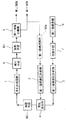
次に、本発明に係る装置の構成について、図面に基づいて詳細に説明する。図1は本発明の製造装置の一構成例を示す概略説明図である。この装置においては、基本的な構成として、多孔体処理部1、第一溶媒高圧供給部2、第二溶媒高圧供給部3、高圧混合部4を備えたものである。これらの基本構成に付随して、第一溶媒分離部5、第二溶媒受槽6、冷却手段7、加熱手段8a,8b、減圧手段9が設けられ、また必要によって第一溶媒貯蔵部10aが設けられる。尚、取り扱う第一の溶媒、第二の溶媒の種類、条件等により、高圧混合部4の前や減圧手段9の前など、図1と異なる位置に加熱手段8a、加熱手段8bを設置したり、或いは、それらを設置しない場合もある。
Next, the configuration of the apparatus according to the present invention will be described in detail based on the drawings. FIG. 1 is a schematic explanatory view showing an example of the configuration of the manufacturing apparatus of the present invention. In this apparatus, as a basic configuration, a porous body processing unit 1, a first solvent high pressure supply unit 2, a second solvent high
こうした装置において、第一溶媒高圧供給部2には、多孔体処理部1で処理される湿潤体(例えば、湿潤ゲル)中に含まれる液体溶媒(第一の液体溶媒)と同種の液体溶媒が供給されており、この液体溶媒は第一溶媒高圧供給部2から高圧状態で高圧混合部4に供給される。また、第二溶媒高圧供給部3には置換用の第二の溶媒が供給されており、この溶媒は第二溶媒高圧供給部3から高圧状態で高圧混合部4に供給される。尚、第二溶媒高圧供給部3には、第二溶媒受槽6から冷却手段7を介して、低圧の第二の溶媒が供給される。図1に示していないが、第一溶媒分離部5から排出される第二の溶媒を熱交換器、或いは、精製器等を経由した後に、第二溶媒受槽6に戻し、再利用しても良い。
In such an apparatus, the first solvent high-pressure supply unit 2 has a liquid solvent of the same type as the liquid solvent (first liquid solvent) contained in the wet body (eg, wet gel) processed in the porous body processing unit 1. This liquid solvent is supplied from the first solvent high pressure supply unit 2 to the high
高圧混合部4では、供給されてきた各溶媒(第一の溶媒と同種の溶媒および第二の溶媒)が所定の割合で混合されて混合溶媒とされる。そして、この混合溶媒は加熱手段8aによって加熱された後、多孔体処理部1に送られる。このときの加熱では、混合溶媒が超臨界状態となる温度に設定される。
In the high-
多孔体処理部1には、第一の液体溶媒を含有する湿潤体(例えば、湿潤ゲル)が設置されており、この湿潤体は供給されてきた混合溶媒と接触され、湿潤体中の第一の溶媒は混合溶媒中の第二の溶媒と徐々に置換されることになる。混合溶媒の供給に際しては、前記第一溶媒供給部2および第二溶媒高圧供給部3からの各溶媒の供給量を制御することによって、混合溶媒中の各溶媒の混合比率を変えることができ、第二の溶媒の混合比率が徐々に大きくなるように制御できる。
The porous body processing unit 1 is provided with a wet body (for example, a wet gel) containing the first liquid solvent. The wet body is brought into contact with the supplied mixed solvent, and the first wet body is in the first position. This solvent is gradually replaced with the second solvent in the mixed solvent. In supplying the mixed solvent, by controlling the amount of each solvent supplied from the first solvent supply unit 2 and the second solvent high
即ち、図1に示した多孔体の製造装置では、前記第一溶媒供給部2および第二溶媒高圧供給部3からの各溶媒の供給量を制御することによって、混合溶媒中の各溶媒の混合比率を変える第一の溶媒の供給量と第二の溶媒の供給量の比率を変化させつつ操業するように構成したものである。尚、第一の溶媒高圧供給部2および第二溶媒高圧供給部3からの各溶媒の供給量を制御するに当って、第一溶媒高圧供給部2および第二溶媒高圧供給部3が供給しようとする各溶媒の供給量を正しく供給することが可能になるよう、いわゆるフィードバック制御等にて各溶媒の供給量を制御する構成であることが好ましい。例えば、第一溶媒高圧供給部2および第二溶媒高圧供給部3が、各溶媒の供給口付近に流量計等を内蔵するものであることが好ましい。尚且つ、第一溶媒高圧供給部2および第二溶媒高圧供給部3が、前記流量計等から出力される検出量と、供給の過程に応じて予め設定された供給量とに基づいて、設定通りに各溶媒が供給されるように、制御するものであることが好ましい。但し、本発明はこうした構成に限定されるものではなく、要するに、混合溶媒中の各溶媒の混合比率を変えることのできるように構成されていれば足りる。
That is, in the porous body manufacturing apparatus shown in FIG. 1, the amount of each solvent in the mixed solvent is mixed by controlling the amount of each solvent supplied from the first solvent supply unit 2 and the second solvent high
多孔体処理部1に供給された混合溶媒は、減圧手段9、加熱手段8b、第一溶媒分離部5に送られ、第一の溶媒と第二の溶媒に分離される。混合溶媒中における第二の溶媒の比率を増大、すなわち第一の溶媒の比率を低下させつつ混合溶媒を供給し、次いで第一の溶媒の供給を停止し、第二の溶媒のみを供給する。そのうち混合溶媒中における第一の溶媒の混合比率は概ね零となるが、その後も第二の溶媒の供給を継続する。それによって、多孔体処理部1内の湿潤体は、溶媒置換が行われつつ乾燥され、溶媒置換が完了した後には第一の溶媒の混合比率が概ね零である混合溶媒、すなわちほぼ第二の溶媒のみによって乾燥が継続される。最終的には、第二の溶媒の供給が止められ、多孔体処理部1内を減圧した後に、元は湿潤体であった、乾燥された多孔体が多孔体処理部1から取り出される。
The mixed solvent supplied to the porous body processing unit 1 is sent to the
この装置においては、必要によって第一溶媒貯蔵部10aが設けられ、この第一溶媒貯蔵部10aには、第一溶媒分離部5で分離された第一の溶媒を蓄えるようにされる。そして、蓄えられた第一の溶媒は、第一溶媒高圧供給部2に循環して再利用される。尚、第一溶媒分離部5の分離条件によっては、分離された第一の溶媒中に本来含まれるべきでない第二の溶媒が多量に溶解している場合がある。従って、第一溶媒貯蔵部10aには、溶媒を加熱する機能等を付属させて、第一の溶媒中に溶解している第二の溶媒を除去するようにしても良い。
In this apparatus, a first
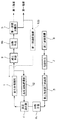
図2は、本発明に係る製造装置の他の構成例を示す概略説明図である。この装置の基本的構成は、前記図1に示した装置構成と類似し、対応する部分には同一の参照を付すことによって重複説明を避ける。 FIG. 2 is a schematic explanatory view showing another configuration example of the manufacturing apparatus according to the present invention. The basic configuration of this apparatus is similar to the apparatus configuration shown in FIG. 1, and the same reference numerals are given to corresponding parts to avoid redundant description.
この装置においては、図1に示した装置における第一溶媒高圧供給部2の代わりに、高圧溶媒循環部12を設け、湿潤体中に含まれる第一の溶媒を循環して混合溶媒の一部として利用するように構成したものである。この装置においては、第一の溶媒を含有する湿潤体は、多孔体処理部1内に設置されるが、この湿潤体に含まれる第一の溶媒を予め高圧溶媒循環部12に送って高圧混合部4から多孔体処理部1で循環させておく。この溶媒の循環は、溶媒が高圧状態にあるままで行われる。そして第二溶媒高圧供給部3からの第二の溶媒を、加熱手段8cを介して高圧混合部4に供給することによって、高圧混合部4内で第一の溶媒と第二の溶媒が所定の混合比率で混合されて混合溶媒とされた後、多孔体処理部1に送られ、同様の処理が行われる。このとき、第二溶媒高圧供給部3からの第二の溶媒の供給量を変化させることによって、溶媒混合部4から多孔体処理部1に供給される混合溶媒中における第二の溶媒の混合比率を変化させることができる。
In this apparatus, instead of the first solvent high-pressure supply unit 2 in the apparatus shown in FIG. 1, a high-pressure
尚、この装置においても、必要によって第一溶媒貯蔵部10bが設けられ、この第一溶媒貯蔵部10bには、第一溶媒分離部5で分離された第一の溶媒を蓄えるようにできる。そして、蓄えられた第一の溶媒は、多孔体処理部1に循環して再利用される。ここで第一の溶媒の多孔体処理部1への供給は、多孔体処理部1が常圧にある時にのみ行われる。
Also in this apparatus, a first
他の構成は、基本的に前記図1に示した装置と同じであるが、こうした装置構成によっても本発明方法を有効に実施することができる。 The other configuration is basically the same as that of the apparatus shown in FIG. 1, but the method of the present invention can be effectively implemented by such an apparatus configuration.
図3は、本発明に係る製造装置の更に他の構成例を示す概略説明図である。この装置の基本的構成は、前記図1に示した装置構成と類似し、対応する部分には同一の参照を付すことによって重複説明を避ける。 FIG. 3 is a schematic explanatory view showing still another configuration example of the manufacturing apparatus according to the present invention. The basic configuration of this apparatus is similar to the apparatus configuration shown in FIG. 1, and the same reference numerals are given to corresponding parts to avoid redundant description.
この装置においては、図1に示した装置に加え、前記多孔体処理部1に、該多孔体処理部に供給される高圧混合溶媒の圧力を検出する圧力検出手段13を備えている。そして、前記圧力検出手段13で検出された信号に基づき、前記減圧手段9を制御して、前記高圧混合溶媒の圧力を徐々に小さくしつつ操業するように構成したものである。尚、ここで言う「高圧混合溶媒の圧力を徐々に小さく」とは、混合溶媒を供給する過程を経るに従って、混合溶媒の圧力が小さくなるように供給するという意味である。またその意味するところは、混合溶媒の圧力が連続的に滑らかに小さくなるように混合溶媒を供給することに限定されるものではなく、その圧力が段階的に小さくなるように、混合溶媒を供給するものであっても良い。
In this apparatus, in addition to the apparatus shown in FIG. 1, the porous body processing section 1 is provided with a pressure detection means 13 for detecting the pressure of the high-pressure mixed solvent supplied to the porous body processing section. Then, based on the signal detected by the
図4は、本発明に係る製造装置の他の構成例を示す概略説明図である。この装置の基本的構成は、前記図2に示した装置構成と類似し、対応する部分には同一の参照を付すことによって重複説明を避ける。 FIG. 4 is a schematic explanatory diagram showing another configuration example of the manufacturing apparatus according to the present invention. The basic configuration of this apparatus is similar to the apparatus configuration shown in FIG. 2, and the same reference numerals are given to corresponding parts to avoid redundant description.
この装置においては、図2に示した装置に加え、前記多孔体処理部1に、該多孔体処理部に供給される高圧混合溶媒の圧力を検出する圧力検出手段14を備えている。そして、前記圧力検出手段13で検出された信号に基づき、前記減圧手段9を制御して、前記高圧混合溶媒の圧力を徐々に小さくしつつ操業するように構成したものである。尚、ここで言う「高圧混合溶媒の圧力が徐々に小さく」とは、前記図3に示した装置に関して述べた意味と同じである。
In this apparatus, in addition to the apparatus shown in FIG. 2, the porous body processing unit 1 is provided with a pressure detection means 14 for detecting the pressure of the high-pressure mixed solvent supplied to the porous body processing unit. Then, based on the signal detected by the
以下、本発明を実施例によって更に詳細に説明するが、下記実施例は本発明を限定する性質のものではなく、前・後記の趣旨に徴して設計変更することはいずれも本発明の技術的範囲に含まれるものである。 Hereinafter, the present invention will be described in more detail by way of examples. However, the following examples are not intended to limit the present invention, and any design changes in accordance with the gist of the preceding and following descriptions are technical aspects of the present invention. It is included in the range.
シリカエアロゲルを得るために、アルコキシシラン、テトラメトキシシラン、溶媒として、エタノールを使用し、触媒および加水分解用の水としてアンモニア水溶液を添加混合して、アルコキシシランを加水分解し、縮重合させ、ゲル状化合物を得た。このゲル状化合物にイソプロパノールを添加し、加熱処理した後(いわゆる熟成工程)、溶媒部分を完全に置換したもの(これを「アルコゲル」と呼ぶ)を得た。 In order to obtain silica aerogel, alkoxysilane, tetramethoxysilane, ethanol as a solvent, an ammonia aqueous solution as a catalyst and hydrolysis water are added and mixed to hydrolyze alkoxysilane, polycondensate, gel A compound was obtained. After adding isopropanol to this gel compound and heat-treating (a so-called aging step), a product in which the solvent portion was completely replaced (referred to as “alcogel”) was obtained.
こうして得られたアルコゲル(湿潤ゲル)を用い、その雰囲気条件を下記(A)〜(G)に示す各方法で処理して乾燥させ、そのときのエアロゲルの生成状態について調査した。このときの乾燥に際しては、ガラス窓付きの高圧容器を用い、該容器内を観察しながら行った。 Using the thus obtained alcogel (wet gel), the atmosphere conditions were treated and dried by the methods shown in the following (A) to (G), and the formation state of the airgel at that time was investigated. The drying at this time was performed using a high-pressure vessel with a glass window while observing the inside of the vessel.
[(A)高圧容器内に超臨界二酸化炭素を供給する方法]
高圧容器内にイソプロパノール(IPA)を満たし、前記アルコゲルを1枚入れた蓋を閉じ、高圧容器を60℃に(図5のA)、二酸化炭素で13MPaまで加圧し(図5のB)、その後60℃、13MPaの超臨界二酸化炭素を供給し続け、高圧容器内のIPAを二酸化炭素で置換し(図5のBからC)、その後高圧容器内を減圧し(図5のCからD)、ゲルを容器内から取り出した。
[(A) Method of supplying supercritical carbon dioxide into a high-pressure vessel]
Fill the high-pressure vessel with isopropanol (IPA), close the lid containing the one alcogel, pressurize the high-pressure vessel to 60 ° C. (A in FIG. 5), pressurize with carbon dioxide to 13 MPa (B in FIG. 5), and then Continue to supply supercritical carbon dioxide at 60 ° C. and 13 MPa, replace IPA in the high-pressure vessel with carbon dioxide (B to C in FIG. 5), and then depressurize the high-pressure vessel (C to D in FIG. 5). The gel was removed from the container.
その結果、全ての処理を7時間で終えた場合、高圧容器内のIPAを超臨界二酸化炭素で置換する工程において、イソプロパノールと超臨界二酸化炭素との間に明確な界面が生じ、結果としてゲルにクラックが入ることが確認できた。尚、イソプロパノールと二酸化炭素の相互拡散で二相界面が生じないように、置換する工程で超臨界二酸化炭素の供給を一時停止するか、非常にゆっくりと流すようにした場合は、ゲルにクラックが入らないことも確認できた。但し、その場合は全ての処理に9時間もの長時間を要することとなった。また、容器内のスペーサを外し、容器深さを1.6倍とし、アルコゲルを容器内に2枚入れて乾燥した場合には、ゲルにクラックが入らないようにするために、置換工程で、上記と同じように、60℃、13MPaの超臨界二酸化炭素を10cc/minの流量で流した場合、770分間流し続けることが必要となり、全ての処理には約14時間もの長時間を必要とした。 As a result, when all the treatments are completed in 7 hours, in the step of replacing IPA in the high-pressure vessel with supercritical carbon dioxide, a clear interface is formed between isopropanol and supercritical carbon dioxide, resulting in the gel. It was confirmed that cracks occurred. In addition, if the supply of supercritical carbon dioxide is temporarily stopped or flowed very slowly in the replacement process so that a two-phase interface does not occur due to the mutual diffusion of isopropanol and carbon dioxide, cracks will occur in the gel. It was confirmed that it did not enter. However, in that case, it took 9 hours for all the processes. In addition, when the spacer in the container is removed, the container depth is 1.6 times, and two alcoholcogels are put in the container and dried, in order to prevent the gel from cracking, in the replacement step, As described above, when supercritical carbon dioxide at 60 ° C. and 13 MPa was flowed at a flow rate of 10 cc / min, it was necessary to continue to flow for 770 minutes, and all treatments required a long time of about 14 hours. .
[(B)高圧容器内に超臨界二酸化炭素とイソプロパノールの混合溶媒を供給する方法]
前記図1に示した装置を用い、高圧容器(多孔体処理部1に相当)内にイソプロパノールを満たし、前記アルコゲルを入れて蓋を閉じ、高圧容器を60℃に加熱した後、二酸化炭素で13MPaまで加圧し、その後60℃、13MPaの超臨界二酸化炭素とイソプロパノールの混合溶媒を供給した。このとき、イソプロパノールの質量比が徐々に減少するように(例えば95質量%→90質量%→85質量%…)イソプロパノールと二酸化炭素を混合し、高圧容器内に供給した。こうした供給では、イソプロパノールの質量比が減少するに従って、高圧容器内のイソプロパノール濃度も減少している。
[(B) Method of supplying a mixed solvent of supercritical carbon dioxide and isopropanol into a high-pressure vessel]
Using the apparatus shown in FIG. 1, the high-pressure vessel (corresponding to the porous body processing unit 1) is filled with isopropanol, the alcogel is placed, the lid is closed, the high-pressure vessel is heated to 60 ° C., and then 13 MPa with carbon dioxide. Then, a mixed solvent of supercritical carbon dioxide and isopropanol at 60 ° C. and 13 MPa was supplied. At this time, isopropanol and carbon dioxide were mixed and supplied into the high-pressure vessel so that the mass ratio of isopropanol gradually decreased (for example, 95 mass% → 90 mass% → 85 mass%). In such a supply, as the mass ratio of isopropanol decreases, the concentration of isopropanol in the high-pressure vessel also decreases.
供給する混合流体中のイソプロパノールの質量比を0%とした後、しばらくの時間を超臨界二酸化炭素だけの供給とし、高圧容器内のイソプロパノールが0.5%以下になってから減圧した。 After the mass ratio of isopropanol in the mixed fluid to be supplied was 0%, the supercritical carbon dioxide was supplied for a while, and the pressure was reduced after the isopropanol in the high-pressure vessel became 0.5% or less.
こうした方法によれば、上記(A)ではゲルにクラックが入ることになった処理時間(7時間)であっても界面ができることなく、乾燥工程中にゲルにクラックが入ることはなかった。 According to such a method, in (A) above, the gel was not cracked during the drying process without forming an interface even during the treatment time (7 hours) in which the gel was cracked.
[(C)高圧容器から排出された溶媒を循環させ、徐々に超臨界二酸化炭素を混合する方法]
前記図4に示した装置を用い、高圧容器(多孔体処理部1に相当)内にイソプロパノールを満たし、前記アルコゲルを入れて蓋を閉じ、高圧容器を60℃に加熱した後、二酸化炭素で13MPaまで加圧し、高圧容器から排出された溶媒を循環ポンプ(高圧溶媒循環部12)によって高圧混合部4を介して高圧容器に供給することにより、この溶媒を循環させた。その後この溶媒を循環させたままで、60℃、13MPaの超臨界二酸化炭素を供給した。このとき、高圧容器内の圧力が13MPaで維持できるように混合溶媒を系外に排出されるように、圧力検出手段14の信号に基づき、減圧手段9を制御した。その結果、高圧容器内のイソプロパノールの濃度が徐々に減少し、最終的に超臨界二酸化炭素のみの状態となった。その後しばらくの時間超臨界二酸化炭素を供給し、高圧容器内のイソプロパノールが完全になくなってから減圧した。
[(C) Method of circulating the solvent discharged from the high-pressure vessel and gradually mixing supercritical carbon dioxide]
Using the apparatus shown in FIG. 4, the high-pressure vessel (corresponding to the porous body processing unit 1) is filled with isopropanol, the alcogel is placed, the lid is closed, the high-pressure vessel is heated to 60 ° C., and then 13 MPa with carbon dioxide. The solvent was circulated by supplying the solvent discharged from the high-pressure vessel to the high-pressure vessel via the high-
こうした方法によっても、上記(A)ではゲルにクラックが入ることになった処理時間(7時間)であっても界面ができることなく、乾燥工程中にゲルにクラックが入ることが無かった。すなわち、上記(A)の場合は、溶媒の相互拡散速度等に依存した二相界面が生じない条件で処理する必要があり、そのためには長時間が処理に必要となる。これに対して、本発明[(B),(C)]の場合は、ゲルの周囲の混合溶媒の濃度を自由に制御できるため、混合溶媒の流量に制限がなく、大型或いは、複数枚のゲルの周囲の流速を自由に設定でき、短時間での均一な処理が可能となる。 Even with such a method, in (A) above, the gel was not cracked during the drying process without forming an interface even during the treatment time (7 hours) in which the gel was cracked. That is, in the case of the above (A), it is necessary to perform the treatment under conditions that do not cause a two-phase interface depending on the mutual diffusion rate of the solvent, and for this purpose, a long time is required. On the other hand, in the case of the present invention [(B), (C)], since the concentration of the mixed solvent around the gel can be freely controlled, there is no restriction on the flow rate of the mixed solvent. The flow velocity around the gel can be freely set, and uniform processing can be performed in a short time.
[(D)高圧容器から排出された溶媒を循環させ、徐々に超臨界二酸化炭素を混合する他の方法]
前記図2に示した装置を用い、高圧容器(多孔体処理部1に相当)内にイソプロパノールを満たし、前記アルコゲルを入れて蓋を閉じ、高圧容器を60℃に加熱した後、二酸化炭素で13MPaまで加圧し、高圧容器から排出された溶媒を循環ポンプ(高圧溶媒循環部12)によって高圧混合部4を介して高圧容器に供給することにより、この溶媒を循環させた。その後この溶媒を循環させたままで、高圧混合部4を介して60℃、13MPaの超臨界二酸化炭素を供給した。但し、超臨界二酸化炭素の供給量を当初20cc/minとしたが、と超臨界二酸化炭素の供給を開始してから180分経過後に、超臨界二酸化炭素の供給量を35cc/minに増加した。即ち、第二の溶媒である超臨界二酸化炭素の混合比率を徐々に大きくするに当って、その超臨界二酸化炭素の混合比率の増加の割合自体を段階的に(徐々に)大きくした。その結果、超臨界二酸化炭素の供給量を増加してから100分後には、高圧容器内のイソプロパノール濃度は0.5%以下となった。イソプロパノール濃度が0.5%以下となってから、更に30分かけて減圧した。結果的に、全ての処理に必要な時間は約5.7時間であった。
[(D) Other methods of circulating the solvent discharged from the high-pressure vessel and gradually mixing the supercritical carbon dioxide]
Using the apparatus shown in FIG. 2, the high-pressure vessel (corresponding to the porous body processing unit 1) is filled with isopropanol, the alcogel is placed, the lid is closed, the high-pressure vessel is heated to 60 ° C., and then 13 MPa with carbon dioxide. The solvent was circulated by supplying the solvent discharged from the high-pressure vessel to the high-pressure vessel via the high-
こうした方法[本発明方法(D)]によっても、多孔体にクラック等が発生するのを防止しつつ多孔体を効率的に製造することができる。尚、このように、超臨界二酸化炭素の混合比率の増加の割合自体を段階的(徐々に)大きくしながら操業することにより、処理時間を上記(C)の場合よりも短くすることが可能になった。 Also by such a method [the method (D) of the present invention], the porous body can be efficiently produced while preventing the occurrence of cracks and the like in the porous body. In this way, the operation time can be made shorter than in the case of the above (C) by operating while increasing the mixing rate of the supercritical carbon dioxide in a stepwise (gradual) manner. became.
[(E)高圧容器から排出された溶媒を循環させ、徐々に超臨界二酸化炭素を混合する更に他の方法]
前記図2に示した装置を用い、高圧容器(多孔体処理部1に相当)内にイソプロパノールを満たし、前記アルコゲルを入れて蓋を閉じ、高圧容器を60℃に加熱した後、二酸化炭素で13MPaまで加圧し、高圧容器から排出された溶媒を循環ポンプ(高圧溶媒循環部12)によって高圧混合部4を介して高圧容器に供給することにより、この溶媒を循環させた。その後この溶媒を循環させたままで、60℃の超臨界二酸化炭素を供給した。このとき、高圧混合溶媒(当初はイソプロパノールのみ)の圧力を、当初13MPaとしたが、超臨界二酸化炭素の供給開始後、40分後には11.5MPaへ、80分後には10MPaへ低下させた。即ち、高圧混合溶媒に圧力を徐々に小さくした。その結果、300分後の高圧容器内のイソプロパノール濃度は0.5%以下となった。結果的に、全ての処理に必要な時間は約6時間であった。
[(E) Still another method of circulating the solvent discharged from the high-pressure vessel and gradually mixing the supercritical carbon dioxide]
Using the apparatus shown in FIG. 2, the high-pressure vessel (corresponding to the porous body processing unit 1) is filled with isopropanol, the alcogel is placed, the lid is closed, the high-pressure vessel is heated to 60 ° C., and then 13 MPa with carbon dioxide. The solvent was circulated by supplying the solvent discharged from the high-pressure vessel to the high-pressure vessel via the high-
こうした方法[本発明方法(E)]によっても、多孔体にクラック等が発生するのを防止しつつ多孔体を効率的に製造することができる。尚、このように、混合溶媒の圧力を徐々に小さくすることにより、処理時間を上記(C)の場合よりも短くすることが可能になった。 Also by such a method [the method (E) of the present invention], the porous body can be efficiently produced while preventing the occurrence of cracks and the like in the porous body. In this way, by gradually reducing the pressure of the mixed solvent, the treatment time can be made shorter than in the case of (C).
[(F)高圧容器から排出された溶媒を循環させ、徐々に超臨界二酸化炭素を混合する他の方法]
前記図4に示した装置を用い、高圧容器(多孔体処理部1に相当)内にイソプロパノールを満たし、前記アルコゲルを1枚入れて蓋を閉じ、高圧容器を60℃に加熱した後、二酸化炭素で13MPaまで30分かけて加圧し、その後、循環ポンプ(高圧溶媒循環部12)によって高圧容器から排出された溶媒を循環させ、超臨界二酸化炭素を20cc/minで供給した。このとき、高圧容器内の圧力が13MPaを維持できるように、圧力検出手段14の信号に基づき、減圧手段9を、高圧容器から排出される混合溶媒を系外に排出するように制御した。その結果、高圧容器内のイソプロパノール濃度は徐々に減少し、360分後にイソプロパノール濃度を測定すると、0.5%以下となっていたため、その後、30分かけて減圧した。結果的に、全ての処理に必要な時間は約7時間であった。
[(F) Other methods of circulating supercritical carbon dioxide gradually by circulating solvent discharged from high-pressure vessel]
Using the apparatus shown in FIG. 4, the high-pressure vessel (corresponding to the porous body processing unit 1) is filled with isopropanol, one sheet of the alcogel is placed, the lid is closed, and the high-pressure vessel is heated to 60 ° C. Then, the pressure was increased to 13 MPa over 30 minutes, and then the solvent discharged from the high-pressure vessel was circulated by a circulation pump (high-pressure solvent circulation unit 12), and supercritical carbon dioxide was supplied at 20 cc / min. At this time, based on the signal from the pressure detection means 14, the decompression means 9 was controlled to discharge the mixed solvent discharged from the high pressure container out of the system so that the pressure in the high pressure container could be maintained at 13 MPa. As a result, the isopropanol concentration in the high-pressure vessel gradually decreased, and when the isopropanol concentration was measured after 360 minutes, it was 0.5% or less, and then the pressure was reduced over 30 minutes. As a result, the time required for all treatments was about 7 hours.
[(G)高圧容器から排出された溶媒を循環させ、徐々に超臨界二酸化炭素を混合する他の方法]
上記(F)の方法とほぼ同様の手順としたが、この方法で容器内のスペーサを外し、容器深さを1.6倍とし、アルコゲルを容器内に2枚入れ、超臨界二酸化炭素の供給量を32cc/minとした。その結果、上記(F)の方法と同様、全ての処理に必要な時間は約7時間であった。
[(G) Other methods of circulating the solvent discharged from the high-pressure vessel and gradually mixing the supercritical carbon dioxide]
The procedure was substantially the same as the above method (F), but the spacer in the container was removed by this method, the container depth was increased 1.6 times, two alcogels were placed in the container, and supercritical carbon dioxide was supplied. The amount was 32 cc / min. As a result, similar to the method (F), the time required for all treatments was about 7 hours.
こうした方法[本発明方法(F),(G)]によっても、上記(A)ではゲルにクラックが入ることになった処理時間(7時間)であっても界面ができることなく、乾燥工程中にゲルにクラックが入ることが無かった。また、上記(F),(G)のように、アルコゲルの枚数を増やしても、容器内の濃度の変化を自由に設定できるので、1枚しか処理できない場合と同様に、短時間での処理が可能となり、効率的な多孔体の工業的生産が可能である。 Even by such a method [the present invention methods (F) and (G)], the interface is not formed even during the treatment time (7 hours) in which the gel is cracked in the above (A), and during the drying process. There was no crack in the gel. Also, as in (F) and (G) above, even if the number of alcogels is increased, the change in the concentration in the container can be set freely, so that only a single sheet can be processed, the processing in a short time This enables efficient industrial production of porous bodies.
従来のように、置換用の溶媒だけを供給する方法では、置換速度を制限すると、処理容器の大きさを大きくすればするほど処理時間が長くなる。しかしながら、本発明では、湿潤体中に含まれている溶媒と同一または同種の溶媒と置換用溶媒を混合した混合溶媒を供給するようにしたので、処理容器内全体の溶媒濃度を均一に連続的に変化させ、置換用の溶媒へ効率良く置換することができる。その結果として、処理容器の大きさを大きくしても、処理時間が長くならず、多孔体の効率的な生産が可能となる。 In the conventional method in which only the solvent for replacement is supplied, if the replacement speed is limited, the processing time increases as the size of the processing container increases. However, in the present invention, since the mixed solvent in which the same or the same type of solvent as that contained in the wet body and the solvent for substitution are mixed is supplied, the solvent concentration in the entire processing container is uniformly and continuously increased. And can be efficiently replaced with a solvent for replacement. As a result, even if the size of the processing container is increased, the processing time does not become long and the porous body can be efficiently produced.
また、第二の溶媒の混合比率を徐々に大きくするに当って、その第二の溶媒の混合比率の増加の割合自体を徐々に大きくすることにより、クラック発生に影響のある、置換初期の置換速度を抑えながら、置換後期の置換速度を上げることができる。その結果として、処理時間を短くすることができ、更に多孔体の効率的な生産が可能となる。 In addition, when the mixing ratio of the second solvent is gradually increased, the increase in the mixing ratio of the second solvent itself is gradually increased, thereby affecting the occurrence of cracks. It is possible to increase the replacement speed in the later stage of replacement while suppressing the speed. As a result, the processing time can be shortened and the porous body can be efficiently produced.
更に、混合溶媒の圧力を徐々に小さくすることによって、置換用の溶媒の濃度が低下し、湿潤体中に含まれる溶媒と置換用の溶媒の濃度が相対的に小さくなることから、置換速度が向上し、多孔体の効率的な生産が可能となる。 Further, by gradually reducing the pressure of the mixed solvent, the concentration of the solvent for substitution decreases, and the concentration of the solvent contained in the wet body and the concentration of the solvent for substitution becomes relatively small, so that the substitution rate is increased. It is possible to improve the production efficiency of the porous body.
1 多孔体処理部
2 第一溶媒高圧供給部
3 第二溶媒高圧供給部
4 高圧混合部
5 第一溶媒分離部
12 高圧溶媒循環部
DESCRIPTION OF SYMBOLS 1 Porous body process part 2 1st solvent high
Claims (16)
前記第一の溶媒と同一または同種の溶媒を高圧状態にして供給する第一溶媒高圧供給部と、
前記第二の溶媒を高圧状態にして供給する第二溶媒高圧供給部と、
前記第一の溶媒と第二の溶媒を高圧状態で混合する高圧混合部と、
前記高圧混合部から供給された高圧混合溶媒を、処理槽内に設置された湿潤体と接触させて処理する多孔体処理部と、
を備えたものであることを特徴とする多孔体の製造装置。 In a porous body manufacturing apparatus configured to manufacture a porous body by replacing the first solvent in a wet body containing a first liquid solvent with a second solvent in a high-pressure state to perform a drying treatment ,
A first solvent high pressure supply section for supplying the same or the same kind of solvent as the first solvent in a high pressure state;
A second solvent high pressure supply section for supplying the second solvent in a high pressure state;
A high pressure mixing section for mixing the first solvent and the second solvent in a high pressure state;
A porous body processing unit for processing the high-pressure mixed solvent supplied from the high-pressure mixing unit in contact with a wet body installed in a processing tank;
An apparatus for producing a porous body, comprising:
前記第一の溶媒を含有する前記湿潤体が設置されて処理される多孔体処理部と、
多孔体処理部から排出された高圧溶媒を循環供給する高圧溶媒循環部と、
前記第二の溶媒を高圧状態にして供給する第二溶媒高圧供給部と、
前記高圧溶媒循環部からの溶媒と前記第二溶媒高圧供給部からの前記第二の溶媒を高圧状態で混合し、その後、前記多孔体処理部に混合溶媒を供給する高圧混合部と、
を備えたものであることを特徴とする多孔体の製造装置。 In a porous body manufacturing apparatus configured to manufacture a porous body by replacing the first solvent in a wet body containing a first liquid solvent with a second solvent in a high-pressure state to perform a drying treatment ,
A porous body processing section in which the wet body containing the first solvent is installed and processed;
A high-pressure solvent circulation unit that circulates and supplies the high-pressure solvent discharged from the porous body processing unit;
A second solvent high pressure supply section for supplying the second solvent in a high pressure state;
A high-pressure mixing unit that mixes the solvent from the high-pressure solvent circulation unit and the second solvent from the second solvent high-pressure supply unit in a high-pressure state, and then supplies a mixed solvent to the porous body processing unit;
An apparatus for producing a porous body, comprising:
Priority Applications (1)
| Application Number | Priority Date | Filing Date | Title |
|---|---|---|---|
| JP2005126791A JP4928090B2 (en) | 2004-04-28 | 2005-04-25 | Airgel production method |
Applications Claiming Priority (3)
| Application Number | Priority Date | Filing Date | Title |
|---|---|---|---|
| JP2004133823 | 2004-04-28 | ||
| JP2004133823 | 2004-04-28 | ||
| JP2005126791A JP4928090B2 (en) | 2004-04-28 | 2005-04-25 | Airgel production method |
Related Child Applications (1)
| Application Number | Title | Priority Date | Filing Date |
|---|---|---|---|
| JP2011087772A Division JP5432946B2 (en) | 2004-04-28 | 2011-04-11 | Airgel production equipment |
Publications (2)
| Publication Number | Publication Date |
|---|---|
| JP2005334871A true JP2005334871A (en) | 2005-12-08 |
| JP4928090B2 JP4928090B2 (en) | 2012-05-09 |
Family
ID=35489002
Family Applications (1)
| Application Number | Title | Priority Date | Filing Date |
|---|---|---|---|
| JP2005126791A Expired - Fee Related JP4928090B2 (en) | 2004-04-28 | 2005-04-25 | Airgel production method |
Country Status (1)
| Country | Link |
|---|---|
| JP (1) | JP4928090B2 (en) |
Cited By (6)
| Publication number | Priority date | Publication date | Assignee | Title |
|---|---|---|---|---|
| JP2016522288A (en) * | 2013-05-23 | 2016-07-28 | ネクソルブ・コーポレイシヨン | Airgel synthesis method |
| JP2020529959A (en) * | 2017-11-17 | 2020-10-15 | エルジー・ケム・リミテッド | Manufacturing method of silica airgel blanket using supercritical waste liquid reused |
| JP2020529991A (en) * | 2017-11-13 | 2020-10-15 | エルジー・ケム・リミテッド | Waste solvent purification method |
| JP2022522086A (en) * | 2020-03-12 | 2022-04-14 | ヂェァジァン ユニバーシティ | Method for manufacturing airgel material by plasticizing and foaming solvent |
| JP7305996B2 (en) | 2019-03-15 | 2023-07-11 | 富士フイルムビジネスイノベーション株式会社 | Water Purification Particles, Hydroponic Cultivation Device, and Water Purification Device |
| JP7305995B2 (en) | 2019-03-15 | 2023-07-11 | 富士フイルムビジネスイノベーション株式会社 | Water purification member, hydroponic cultivation device, and water purification device |
Citations (4)
| Publication number | Priority date | Publication date | Assignee | Title |
|---|---|---|---|---|
| JPH10231116A (en) * | 1996-12-20 | 1998-09-02 | Matsushita Electric Works Ltd | Production of hydrophobic aerogel |
| JP2001072408A (en) * | 1999-08-30 | 2001-03-21 | Matsushita Electric Works Ltd | Silica aerogel and its production |
| JP2001089129A (en) * | 1999-09-20 | 2001-04-03 | Agency Of Ind Science & Technol | Production of monolithic composite material of metal compound and silica aerogel using supercritical impregnation |
| US6670402B1 (en) * | 1999-10-21 | 2003-12-30 | Aspen Aerogels, Inc. | Rapid aerogel production process |
-
2005
- 2005-04-25 JP JP2005126791A patent/JP4928090B2/en not_active Expired - Fee Related
Patent Citations (4)
| Publication number | Priority date | Publication date | Assignee | Title |
|---|---|---|---|---|
| JPH10231116A (en) * | 1996-12-20 | 1998-09-02 | Matsushita Electric Works Ltd | Production of hydrophobic aerogel |
| JP2001072408A (en) * | 1999-08-30 | 2001-03-21 | Matsushita Electric Works Ltd | Silica aerogel and its production |
| JP2001089129A (en) * | 1999-09-20 | 2001-04-03 | Agency Of Ind Science & Technol | Production of monolithic composite material of metal compound and silica aerogel using supercritical impregnation |
| US6670402B1 (en) * | 1999-10-21 | 2003-12-30 | Aspen Aerogels, Inc. | Rapid aerogel production process |
Cited By (10)
| Publication number | Priority date | Publication date | Assignee | Title |
|---|---|---|---|---|
| JP2016522288A (en) * | 2013-05-23 | 2016-07-28 | ネクソルブ・コーポレイシヨン | Airgel synthesis method |
| JP2020529991A (en) * | 2017-11-13 | 2020-10-15 | エルジー・ケム・リミテッド | Waste solvent purification method |
| JP7024060B2 (en) | 2017-11-13 | 2022-02-22 | エルジー・ケム・リミテッド | Waste solvent purification method |
| US11465906B2 (en) | 2017-11-13 | 2022-10-11 | Lg Chem, Ltd. | Method for purifying waste solvent |
| JP2020529959A (en) * | 2017-11-17 | 2020-10-15 | エルジー・ケム・リミテッド | Manufacturing method of silica airgel blanket using supercritical waste liquid reused |
| US11891306B2 (en) | 2017-11-17 | 2024-02-06 | Lg Chem, Ltd. | Method for producing silica aerogel blanket by reusing supercritical waste liquid |
| JP7305996B2 (en) | 2019-03-15 | 2023-07-11 | 富士フイルムビジネスイノベーション株式会社 | Water Purification Particles, Hydroponic Cultivation Device, and Water Purification Device |
| JP7305995B2 (en) | 2019-03-15 | 2023-07-11 | 富士フイルムビジネスイノベーション株式会社 | Water purification member, hydroponic cultivation device, and water purification device |
| JP2022522086A (en) * | 2020-03-12 | 2022-04-14 | ヂェァジァン ユニバーシティ | Method for manufacturing airgel material by plasticizing and foaming solvent |
| JP7255911B2 (en) | 2020-03-12 | 2023-04-11 | ヂェァジァン ユニバーシティ | Method for producing airgel materials by solvent plasticization and foaming |
Also Published As
| Publication number | Publication date |
|---|---|
| JP4928090B2 (en) | 2012-05-09 |
Similar Documents
| Publication | Publication Date | Title |
|---|---|---|
| JP4928090B2 (en) | Airgel production method | |
| JP5432946B2 (en) | Airgel production equipment | |
| CN107709424B (en) | Systems and methods for producing aerogel materials | |
| US20040087670A1 (en) | Rapid aerogel production process | |
| CN105536655A (en) | Rapid preparation method for aerogel material | |
| WO2014180299A1 (en) | Method and device for preparing aerogel by drying under reduced pressure | |
| JP7098010B2 (en) | Preparation method of silica airgel | |
| JP6974586B2 (en) | Manufacturing method of silica airgel blanket using supercritical waste liquid reused | |
| JP2014241450A (en) | Supercritical drying method of semiconductor substrate, and substrate processing apparatus | |
| JP2009160481A (en) | Dehydrating apparatus and method | |
| JP2007216438A (en) | Wood modifying method | |
| JP6976656B2 (en) | Power generation system | |
| JPH1176740A (en) | Decomposing method of organic fluorine based waste gas and decomposing device | |
| EP3786112B1 (en) | Supercritical drying method for silica wet gel blanket | |
| JP2003340262A5 (en) | ||
| JP2001026664A (en) | Preparation of porous product | |
| Paguio et al. | Synthesis of resorcinol formaldehyde aerogel using UV photo-initiators for inertial confinement fusion experiments | |
| JP2010179289A (en) | High-pressure treatment method and high-pressure treatment apparatus | |
| JP2009160508A (en) | Ozone water forming apparatus, ozone water forming method, ozone water, ozone aqueous solution, and ozone water or ozone aqueous solution | |
| JP6427458B2 (en) | Method for producing a tank, in particular a car tank | |
| CN115427352B (en) | Method for producing aerogel blanket | |
| JP6836278B2 (en) | Methods and systems for producing polymer / reduced graphene oxide nanocomposites by in-situ reduction of graphene oxide | |
| CN114420540A (en) | Single wafer type wafer cleaning device and control method of overall cleanliness of single wafer type wafer cleaning device | |
| WO2020014828A1 (en) | Methods for forming aerogels | |
| JP4542051B2 (en) | Method for forming porous film |
Legal Events
| Date | Code | Title | Description |
|---|---|---|---|
| A621 | Written request for application examination |
Free format text: JAPANESE INTERMEDIATE CODE: A621 Effective date: 20070928 |
|
| A131 | Notification of reasons for refusal |
Free format text: JAPANESE INTERMEDIATE CODE: A131 Effective date: 20110208 |
|
| A521 | Written amendment |
Free format text: JAPANESE INTERMEDIATE CODE: A523 Effective date: 20110411 |
|
| TRDD | Decision of grant or rejection written | ||
| A01 | Written decision to grant a patent or to grant a registration (utility model) |
Free format text: JAPANESE INTERMEDIATE CODE: A01 Effective date: 20120207 |
|
| A01 | Written decision to grant a patent or to grant a registration (utility model) |
Free format text: JAPANESE INTERMEDIATE CODE: A01 |
|
| A61 | First payment of annual fees (during grant procedure) |
Free format text: JAPANESE INTERMEDIATE CODE: A61 Effective date: 20120210 |
|
| FPAY | Renewal fee payment (event date is renewal date of database) |
Free format text: PAYMENT UNTIL: 20150217 Year of fee payment: 3 |
|
| R150 | Certificate of patent or registration of utility model |
Ref document number: 4928090 Country of ref document: JP Free format text: JAPANESE INTERMEDIATE CODE: R150 Free format text: JAPANESE INTERMEDIATE CODE: R150 |
|
| LAPS | Cancellation because of no payment of annual fees |