JP2005317140A - Disk reproducing device - Google Patents
Disk reproducing device Download PDFInfo
- Publication number
- JP2005317140A JP2005317140A JP2004134929A JP2004134929A JP2005317140A JP 2005317140 A JP2005317140 A JP 2005317140A JP 2004134929 A JP2004134929 A JP 2004134929A JP 2004134929 A JP2004134929 A JP 2004134929A JP 2005317140 A JP2005317140 A JP 2005317140A
- Authority
- JP
- Japan
- Prior art keywords
- disc
- read
- information
- disk
- recorded
- Prior art date
- Legal status (The legal status is an assumption and is not a legal conclusion. Google has not performed a legal analysis and makes no representation as to the accuracy of the status listed.)
- Pending
Links
Images


Abstract
Description
本発明は、MD(ミニディスク)等のディスクを再生するディスク再生装置に関し、特に、ディスクが未記録か否かを判定する機能を備えたディスク再生装置に関する。 The present invention relates to a disc playback device for playing back a disc such as an MD (mini disc), and more particularly to a disc playback device having a function of determining whether or not a disc is unrecorded.
MDは、曲や英会話等の1まとまりの音声情報を1トラックに割当てて録音されるとともに、各トラックの管理情報がUTOC(User’s Table Of Contents)エリアに書き込まれるようになっている。
図3はMDの記憶領域を示す図であり、図に示すように、内周から外周に向けてTOC領域、UTOC領域、プログラム領域、リードアウト領域の順に配置され、最内周のTOC領域は再生専用の領域であり、UTOC領域、プログラム領域、リードアウト領域の各々の開始アドレスや推奨する記録レーザーパワー値等の記録を行うために必要な情報があらかじめ記録されている。
In the MD, a set of audio information such as music and English conversation is recorded by assigning it to one track, and management information of each track is written in a UTOC (User's Table Of Contents) area.
FIG. 3 is a diagram showing the MD storage area. As shown in FIG. 3, the TOC area, UTOC area, program area, and lead-out area are arranged in this order from the inner periphery to the outer periphery. This is a reproduction-only area, and information necessary for recording such as the start address of each of the UTOC area, the program area, and the lead-out area and the recommended recording laser power value is recorded in advance.
UTOC領域には、プログラム領域に記録される情報の開始及び終了アドレス、情報の楽曲名等の目録情報が記録され、プログラム領域への情報の記録後、あるいは消去等の編集がされる毎に書き換えられる。プログラム領域には、例えば圧縮処理が施されたオーディオ信号等の情報が記録され、最外周のリードアウト領域はMDの終端を示す領域であり、情報は記録されない。UTOC領域、プログラム領域、リードアウト領域にはあらかじめ蛇行した案内溝が形成されており、MDに記録を行うために必要な絶対アドレスが付与されている。 In the UTOC area, catalog information such as the start and end addresses of information recorded in the program area and the music title of the information is recorded, and the information is rewritten after the information is recorded in the program area or when editing such as deletion is performed. It is done. For example, information such as an audio signal subjected to compression processing is recorded in the program area, and the outermost lead-out area is an area indicating the end of the MD, and no information is recorded. In the UTOC area, the program area, and the lead-out area, guide grooves meandering in advance are formed, and absolute addresses necessary for recording on the MD are given.
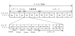
また、UTOC領域は、図4に示すように、48クラスタで構成され、目録情報は03、04、05クラスタアドレスの3クラスタのみに記録される。02クラスタアドレスは最適パワーを実際に記録再生して求めるときに使用するPCA(Power Calibration Area)であり、残りの44クラスタはリザーブされている。目録情報が記録される3クラスタには同一データが記録され、それぞれ00〜07セクタまでが定義され、残りの24セクタはリザーブされている。UTOCセクタ0と呼ぶ00セクタは必須であり、情報の記録開始及び終了アドレス等を目録情報として記録する。他のセクタはオプションであり、楽曲名等を目録情報として記録することができる。リザーブセクタ及び未使用セクタには、0データが記録される。 Further, as shown in FIG. 4, the UTOC area is composed of 48 clusters, and the inventory information is recorded only in three clusters of 03, 04, and 05 cluster addresses. The 02 cluster address is a PCA (Power Calibration Area) used when the optimum power is actually obtained by recording / reproducing, and the remaining 44 clusters are reserved. The same data is recorded in the three clusters in which the catalog information is recorded, each of which is defined from 00 to 07 sectors, and the remaining 24 sectors are reserved. The 00 sector called UTOC sector 0 is indispensable, and information recording start and end addresses are recorded as inventory information. Other sectors are optional, and music titles can be recorded as catalog information. Zero data is recorded in the reserved sector and the unused sector.
上記のUTOC領域に記録された目録情報は、例えば電源の投入時、あるいはMDの挿入時に再生手段により再生され、ディスク再生装置の目録情報記憶部に記憶される(例えば、特許文献1参照。)。
上記のように、ディスク再生装置では、電源の投入時、あるいはディスクの挿入時にUTOC領域に記録された目録情報を再生し、目録情報記憶部に記憶するが、このUTOC領域に記録された目録情報が読み出せない場合には、「未記録ディスク」と判断して再生をストップするようにしている。
このようにディスクが「未記録ディスク」か否かの判断を行う場合、従来はUTOC領域のクラスタ3に記録されている目録情報を読み取り、目録情報が読み出せない場合に、挿入されているディスクが「未記録ディスク」と判断していたが、実際にはディスクにデータが書き込まれているにもかかわらず、情報読み込み時のジッタやディスクの傷、汚れ等の影響でデータエラーが多く、データが読み込めない場合に、「記録済ディスク」を「未記録ディスク」であると判断してしまう恐れがあった。
As described above, the disc playback apparatus plays back the catalog information recorded in the UTOC area when the power is turned on or when the disc is inserted, and stores it in the catalog information storage unit. The catalog information recorded in this UTOC area Is unable to be read, it is determined as an “unrecorded disc” and playback is stopped.
When determining whether or not the disc is an “unrecorded disc” in this way, the disc information that has been conventionally recorded in the cluster 3 in the UTOC area is read and the disc information cannot be read. However, even though data was actually written to the disc, there were many data errors due to the effects of jitter when reading information, scratches on the disc, dirt, etc. May not be able to be read, the “recorded disc” may be judged as an “unrecorded disc”.
本発明は、上記の問題に鑑みてなされたもので、情報読み込み時のジッタやディスクの傷、汚れ等により読取りエラーが多い場合にも、ディスクが未記録か否かを確実に判断することができるディスク再生装置を提供することを目的とする。 The present invention has been made in view of the above problems, and even when there are many reading errors due to jitter at the time of reading information, scratches on the disk, dirt, etc., it is possible to reliably determine whether or not the disk is unrecorded. An object of the present invention is to provide a disc reproducing apparatus that can be used.
上述の目的を達成するため、本発明に係るディスク再生装置(1)は、
ディスクからの情報を再生するための信号を検出する信号検出手段と、上記信号検出手段により検出された信号を処理する制御手段とを備え、上記制御手段がディスクのUTOC領域に記録された情報を読み出すことによりディスクが未記録か否かを判別するディスク再生装置であって、
ディスクの記録有無の判断時に、上記UTOC領域に記録された情報を読み出せないとき、上記制御手段が情報の読取り条件を変更することを特徴とする。
In order to achieve the above object, a disc playback apparatus (1) according to the present invention includes:
A signal detection means for detecting a signal for reproducing information from the disc; and a control means for processing the signal detected by the signal detection means. The control means stores the information recorded in the UTOC area of the disc. A disc playback device that discriminates whether or not a disc is unrecorded by reading,
When the information recorded in the UTOC area cannot be read when determining whether or not the disk is recorded, the control means changes the information reading condition.
また、本発明に係るディスク再生装置(2)は、ディスク再生装置(1)において、
上記ディスクの読取りトラックを一定線速度で走行させる線速度制御手段を備え、
上記UTOC領域に記録された情報を読み出せないとき、上記制御手段が情報の読取り条件として上記線速度制御手段のゲインを変更することを特徴とする。
Also, the disc playback apparatus (2) according to the present invention is the disc playback apparatus (1),
Linear velocity control means for running the disk reading track at a constant linear velocity,
When the information recorded in the UTOC area cannot be read, the control means changes the gain of the linear velocity control means as an information reading condition.
さらに、本発明に係るディスク再生装置(3)は、ディスク再生装置(1)において、
上記信号検出手段が位相同期ループ手段を備え、
上記UTOC領域に記録された情報を読み出せないとき、上記制御手段が情報の読取り条件として上記位相同期ループ手段のゲインを変更することを特徴とする。
Furthermore, the disc playback apparatus (3) according to the present invention includes a disc playback apparatus (1),
The signal detection means comprises phase locked loop means,
When the information recorded in the UTOC area cannot be read, the control means changes the gain of the phase-locked loop means as an information reading condition.
また、本発明に係るディスク再生装置(4)は、ディスク再生装置(1)において、
情報の読取り条件を変更してもディスクのUTOC領域に記録された情報を読み出せないとき、上記制御手段がUTOC領域の他のクラスタに記録された情報を読むことを特徴とする。
Also, the disc playback device (4) according to the present invention is the disc playback device (1),
When the information recorded in the UTOC area of the disc cannot be read even if the information reading condition is changed, the control means reads the information recorded in another cluster of the UTOC area.
本発明に係るディスク再生装置(1)〜(3)によれば、実際にはディスクにデータが書き込まれているにもかかわらず、ジッタ等の影響でデータ読取りエラーが多く、データが読めない場合でも、線速度制御手段や位相同期ループ手段のゲイン等の情報の読取り条件を変更して再度UTOC領域に記録された目録情報が読まれるので、「記録済ディスク」を誤って「未記録ディスク」であると判断する可能性を減少させることができる。 According to the disk reproducing apparatuses (1) to (3) according to the present invention, even when data is actually written on the disk, there are many data reading errors due to jitter and the like, and the data cannot be read. However, since the catalog information recorded in the UTOC area is read again by changing the information reading conditions such as the gain of the linear velocity control means and the phase locked loop means, the “recorded disk” is mistakenly changed to “unrecorded disk”. It is possible to reduce the possibility of determining that it is.
また、本発明に係るディスク再生装置(4)によれば、情報の読取り条件を変更してもディスクのUTOC領域に記録された目録情報を読み出せないとき、UTOC領域の他のクラスタに記録された目録情報が読まれるので、「記録済ディスク」を誤って「未記録ディスク」であると判断する可能性をさらに減少させることができる。 Further, according to the disk reproducing apparatus (4) of the present invention, when the information read from the UTOC area of the disk cannot be read even if the information reading condition is changed, it is recorded in another cluster of the UTOC area. Since the catalog information is read, the possibility that the “recorded disc” is erroneously determined as the “unrecorded disc” can be further reduced.
以下、本発明のディスク再生装置の一実施例について、図面を用いて説明する。
図1は光ディスク再生装置の構成を示すブロック図であり、この光ディスク装置は、スピンドルモータ(S/M)1、光学ヘッド2、信号処理回路3、位相同期ループ(PLL)回路4、D/A変換回路5、コントローラ6、CLV制御回路7、から構成されている。
Hereinafter, an embodiment of a disk reproducing apparatus of the present invention will be described with reference to the drawings.
FIG. 1 is a block diagram showing a configuration of an optical disk reproducing apparatus, which includes a spindle motor (S / M) 1, an optical head 2, a signal processing circuit 3, a phase locked loop (PLL) circuit 4, a D / A. The conversion circuit 5, the controller 6, and the CLV control circuit 7 are configured.
スピンドルモータ1は情報記録媒体である光ディスク10を回転させ、光学ヘッド2は、光ディスク10に光を投射し、光ディスクから反射された光を検出することにより、光ディスク10に記録された情報を再生する。この光学ヘッド2は、光ディスク10の記録面に対して垂直に配置されており、光ディスク10の半径方向へ走行しながら光ディスク10の記録面に光を投射する。
The
光学ヘッド2により再生された信号は信号処理回路3とPLL回路4に入力され、信号処理回路3からのRF再生信号がD/A変換回路5によりアナログ信号に変換されて再生領域に伝達される。一方、PLL回路4は再生信号よりチャンネルクロック(再生信号に同期したデータ読取り用クロック)を生成して信号処理回路3に入力し、信号処理回路3からの集束誤差信号とトラッキング誤差信号を含む誤差信号がコントローラ6に入力される。 The signal reproduced by the optical head 2 is input to the signal processing circuit 3 and the PLL circuit 4, and the RF reproduction signal from the signal processing circuit 3 is converted into an analog signal by the D / A conversion circuit 5 and transmitted to the reproduction region. . On the other hand, the PLL circuit 4 generates a channel clock (data reading clock synchronized with the reproduction signal) from the reproduction signal and inputs it to the signal processing circuit 3, and an error including a focusing error signal and a tracking error signal from the signal processing circuit 3. A signal is input to the controller 6.
このコントローラ6はCPU11、ROM12、RAM13を備え、CPU11は光ディスク装置のハードウェア各部を制御するとともに、ROM12に記憶されたプログラムに基づいて各種のプログラムを実行する。ROM12は光ディスク装置の動作に必要な種々のプログラムを予め記憶しており、RAM13はSRAM等で構成され、プログラムの実行時に発生する一時的なデータを記憶するとともに、目録情報を記憶する。
The controller 6 includes a CPU 11, a
すなわち、コントローラ6は光ディスク再生装置の電源投入時あるいは光ディスク10が装填された時点で、スピンドルモータ1及び光学ヘッド2を駆動し、光ディスクの最内周側に設定されているTOC領域、UTOC領域のデータを抽出し、RAM13に記憶する。そして、曲の再生を行う場合、コントローラ6はRAM13に記憶された情報から各トラック(曲)の開始及び終了アドレスを読み込み、指定された曲の先頭番地へ光学ヘッド2を移動する。
That is, the controller 6 drives the
また、このコントローラ6は、信号処理回路3からの誤差信号を演算処理して、その結果をCLV(一定線速度、Constant Linear Velocity)制御回路7に出力し、このCLV制御回路7がスピンドルモータ1を制御することにより光学ヘッド2が位置するトラックの線速度を一定に制御する。すなわち、光ディスク10の記録面の情報の記録/再生時、光ディスク10を回転させるスピンドルモータ1の回転速度は記録/再生トラックの位置によって変化させなければならず、CLV制御回路7はスピンドルモータ1の回転速度を前もって計算して制御することにより、情報の記録/再生時、ディスクの各トラックが一定線速度で走行するように制御する。
Further, the controller 6 performs an arithmetic processing on the error signal from the signal processing circuit 3 and outputs the result to a CLV (Constant Linear Velocity) control circuit 7, and the CLV control circuit 7 performs the
上記のCLV制御回路7やPLL回路4のゲインを上げると、ディスク回転の変動に対して敏感に応答し、すばやく狙いの回転にあわすことができ、これらの回路のゲインを下げると、ディスク回転の変動に対する応答が鈍くなる。
例えば、ディスクに傷、汚れ等があった場合、CLV制御回路7やPLL回路4のゲインが高すぎると、その傷に対し敏感に反応し、過剰に回転制御を行ってしまうため、読取りエラーが増加する。逆に、これらの回路のゲインが低すぎると、回転制御が充分にできないために、ジッタが多いディスクに対して読取りエラーが増加する。
Increasing the gain of the above CLV control circuit 7 or PLL circuit 4 responds sensitively to fluctuations in the disk rotation and can quickly respond to the target rotation. Decreasing the gain of these circuits reduces the disk rotation. Response to fluctuations becomes dull.
For example, if the disc is scratched, dirty, etc., if the gain of the CLV control circuit 7 or PLL circuit 4 is too high, it will react sensitively to the scratch and perform excessive rotation control, resulting in a read error. To increase. On the other hand, if the gain of these circuits is too low, the rotation control cannot be sufficiently performed, so that a read error increases for a disk with much jitter.
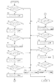
次に、電源の投入時、あるいは光ディスクの挿入時に、光ディスクのUTOC領域に目録情報が記録されているか否かを判別することにより、装填されている光ディスクが「記録済ディスク」か「未記録ディスク」かを判断する場合の作用について、図2のフローチャートにより説明する。
電源の投入時、あるいは光ディスクの挿入時、コントローラ6のCPU11は図2のフローチャートに示す未記録ディスク判定プログラムを開始し、まず、CPU11は光学ヘッド2を光ディスク10の内周側に移動し、CLV制御回路7とPLL回路4のゲインを下げた状態でUTOC領域のクラスタ3のデータを読み、目録情報が正常に読み取れたか否かを判定する(ステップ101)。
Next, when the power is turned on or the optical disc is inserted, it is determined whether or not the catalog information is recorded in the UTOC area of the optical disc, so that the loaded optical disc is “recorded disc” or “unrecorded disc”. 2 will be described with reference to the flowchart of FIG.
When the power is turned on or the optical disk is inserted, the CPU 11 of the controller 6 starts an unrecorded disk determination program shown in the flowchart of FIG. 2. First, the CPU 11 moves the optical head 2 to the inner peripheral side of the optical disk 10, and CLV The data of the cluster 3 in the UTOC area is read with the gains of the control circuit 7 and the PLL circuit 4 lowered, and it is determined whether or not the inventory information has been read normally (step 101).
目録情報が読み取れた場合には、装填されているディスクが「記録済ディスク」であると判断し(ステップ102)、プログラムを終了する。この場合、UTOC部分に傷、汚れ等があって読みにくい状態であっても、CLV制御回路7とPLL回路4のゲインを下げた状態でクラスタ3のデータが読まれるので、これらの傷、汚れに対する応答が鈍くなり、読取りエラーを減らすことができる。 If the inventory information can be read, it is determined that the loaded disc is a “recorded disc” (step 102), and the program is terminated. In this case, even if the UTOC portion has scratches, dirt, etc. and is difficult to read, the data of the cluster 3 is read with the gains of the CLV control circuit 7 and the PLL circuit 4 lowered. The response to is dull and reading errors can be reduced.
ステップ101において、目録情報が読み取れなかった場合、CPU11はCLV制御回路7のゲインを増加した(ステップ103)後、クラスタ3のデータを読み、目録情報が正常に読み取れたか否かを判定する(ステップ104)。目録情報が読み取れた場合には、CPU11は装填されているディスクが「記録済ディスク」であると判断し(ステップ102)、ステップ104でも、目録情報が読み取れなかった場合、CPU11はPLL回路4のゲインを増加した(ステップ105)後、クラスタ3のデータを読み、目録情報が正常に読み取れたか否かを判定する(ステップ106)。
以上のように、CLV制御回路7とPLL回路4のゲインを上げることにより、上記のように、回転ムラに対して敏感に応答するようになるので、もともとジッタが多いディスクの読み取りエラーを減らすことが可能となる。
In
As described above, by increasing the gains of the CLV control circuit 7 and the PLL circuit 4, as described above, it responds sensitively to rotation unevenness, thereby reducing disk read errors that originally have a lot of jitter. Is possible.
一方、ステップ106においても、目録情報が読み取れなかった場合、CPU11はCLV制御回路7とPLL回路4のゲインをもとの小さい状態に復帰させた(ステップ107)後、UTOC領域のクラスタ4のデータを読み、目録情報が正常に読み取れたか否かを判定する(ステップ108)。目録情報が読み取れなかった場合、さらにCPU11はCLV制御回路7のゲインを上げた(ステップ109)後、クラスタ4のデータを読み、目録情報を正常に読み取れたか否かを判定する(ステップ110)。
ステップ110でも、目録情報が読み取れなかった場合、CPU11はPLL回路4のゲインを上げた(ステップ111)後、クラスタ4のデータを読み、目録情報を正常に読み取れたか否かを判定する(ステップ112)。
On the other hand, if the inventory information cannot be read in
Even in
そして、ステップ112おいても、目録情報が読み取れなかった場合、CPU11は、同様に、CLV制御回路7とPLL回路4のゲインをもとの小さい状態に復帰させた状態でのUTOC領域のクラスタ5のデータの読取り、CLV制御回路7及びPLL回路4のゲインを上げた状態でのクラスタ5のデータの読取りを行って、目録情報が正常に読み取れたか否かを判定し(ステップ113〜118)、いずれのステップでも目録情報が読み取れなかった場合は、装填されているディスクが「未記録ディスク」と判断し(ステップ119)、プログラムを終了する。
In
以上のように、実際にはディスクにデータが書き込まれているにもかかわらず、傷やジッタ等の影響でデータ読取りエラーが多く、データが読めない場合でも、CLV制御回路とPLL回路のゲインを変更して再度UTOC領域に記録された目録情報が読まれるので、「記録済ディスク」を誤って「未記録ディスク」であると判断する可能性を減少させることができる。
また、CLV制御回路とPLL回路のゲインを変更してもディスクのUTOC領域に記録された目録情報を読み出せないとき、UTOC領域の他のクラスタに記録された目録情報が読まれるので、「記録済ディスク」を誤って「未記録ディスク」であると判断する可能性をさらに減少させることができる。
As described above, the gain of the CLV control circuit and the PLL circuit is increased even when data cannot be read due to many data reading errors due to scratches, jitter, etc. even though the data is actually written on the disk. Since the catalog information that has been changed and recorded again in the UTOC area is read, the possibility that the “recorded disc” is erroneously determined as the “unrecorded disc” can be reduced.
Further, if the catalog information recorded in the UTOC area of the disc cannot be read even if the gains of the CLV control circuit and the PLL circuit are changed, the catalog information recorded in other clusters in the UTOC area is read. The possibility of erroneously determining “spent disc” as “unrecorded disc” can be further reduced.
上記の実施例では、初めにCLV制御回路とPLL回路のゲインを小さくしてUTOC領域に記録された目録情報を読み、読めない場合にCLV制御回路とPLL回路のゲインを大きくして、再びUTOC領域に記録された目録情報を読み込んだが、初めにCLV制御回路とPLL回路のゲインが大きな状態でUTOC領域に記録された目録情報を読み、読めない場合にCLV制御回路とPLL回路のゲインを小さくして、再びUTOC領域に記録された目録情報を読むようにすることも可能である。 In the above-described embodiment, first, the gain of the CLV control circuit and the PLL circuit is reduced and the catalog information recorded in the UTOC area is read. If it cannot be read, the gain of the CLV control circuit and the PLL circuit is increased and the UTOC is again read. When the catalog information recorded in the area is read, but first the catalog information recorded in the UTOC area is read when the gains of the CLV control circuit and the PLL circuit are large, and the gains of the CLV control circuit and the PLL circuit are reduced. It is also possible to read the catalog information recorded in the UTOC area again.
また、上記の実施例ではUTOC領域に記録された目録情報が読めない場合に変更する読取り条件として、CLV制御回路とPLL回路のゲインを使用したが、他の読取り条件を変えるようにすることも可能である。
さらに、本発明のディスク再生装置は、MDだけでなくCD−R(コンパクトディスク−リライタブル)等の様々なディスクを再生するディスク再生装置に適用することが可能である。
In the above embodiment, the gain of the CLV control circuit and the PLL circuit is used as the reading condition to be changed when the catalog information recorded in the UTOC area cannot be read. However, other reading conditions may be changed. Is possible.
Furthermore, the disc playback apparatus of the present invention can be applied to a disc playback apparatus that plays back various discs such as a CD-R (compact disc-rewritable) as well as an MD.
1 スピンドルモータ(S/M)
2 光学ヘッド
3 信号処理回路
4 PLL回路
5 D/A変換回路
6 コントローラ
7 CLV制御回路
11 CPU
12 ROM
13 RAM
1 Spindle motor (S / M)
2 Optical Head 3 Signal Processing Circuit 4
12 ROM
13 RAM
Claims (4)
ディスクの記録有無の判断時に、上記UTOC領域に記録された情報を読み出せないとき、上記制御手段が情報の読取り条件を変更することを特徴とするディスク再生装置。 A signal detection means for detecting a signal for reproducing information from the disc; and a control means for processing the signal detected by the signal detection means. The control means stores the information recorded in the UTOC area of the disc. A disc playback device that discriminates whether or not a disc is unrecorded by reading,
A disc reproducing apparatus, wherein when the information recorded in the UTOC area cannot be read when determining whether or not the disc is recorded, the control means changes the information reading condition.
上記ディスクの読取りトラックを一定線速度で走行させる線速度制御手段を備え、
上記UTOC領域に記録された情報を読み出せないとき、上記制御手段が情報の読取り条件として上記線速度制御手段のゲインを変更することを特徴とするディスク再生装置。 The disc player according to claim 1, wherein
Linear velocity control means for running the disk reading track at a constant linear velocity,
The disc reproducing apparatus according to claim 1, wherein when the information recorded in the UTOC area cannot be read, the control means changes the gain of the linear velocity control means as an information reading condition.
上記信号検出手段が位相同期ループ手段を備え、
上記UTOC領域に記録された情報を読み出せないとき、上記制御手段が情報の読取り条件として上記位相同期ループ手段のゲインを変更することを特徴とするディスク再生装置。 The disc player according to claim 1, wherein
The signal detection means comprises phase locked loop means,
The disc reproducing apparatus, wherein when the information recorded in the UTOC area cannot be read, the control means changes the gain of the phase-locked loop means as an information reading condition.
情報の読取り条件を変更してもディスクのUTOC領域に記録された情報を読み出せないとき、上記制御手段がUTOC領域の他のクラスタに記録された情報を読むことを特徴とするディスク再生装置。 The disc player according to claim 1, wherein
A disc reproducing apparatus, wherein the control means reads information recorded in another cluster of the UTOC area when the information recorded in the UTOC area of the disc cannot be read even if the information reading condition is changed.
Priority Applications (1)
| Application Number | Priority Date | Filing Date | Title |
|---|---|---|---|
| JP2004134929A JP2005317140A (en) | 2004-04-30 | 2004-04-30 | Disk reproducing device |
Applications Claiming Priority (1)
| Application Number | Priority Date | Filing Date | Title |
|---|---|---|---|
| JP2004134929A JP2005317140A (en) | 2004-04-30 | 2004-04-30 | Disk reproducing device |
Publications (2)
| Publication Number | Publication Date |
|---|---|
| JP2005317140A true JP2005317140A (en) | 2005-11-10 |
| JP2005317140A5 JP2005317140A5 (en) | 2007-06-14 |
Family
ID=35444382
Family Applications (1)
| Application Number | Title | Priority Date | Filing Date |
|---|---|---|---|
| JP2004134929A Pending JP2005317140A (en) | 2004-04-30 | 2004-04-30 | Disk reproducing device |
Country Status (1)
| Country | Link |
|---|---|
| JP (1) | JP2005317140A (en) |
-
2004
- 2004-04-30 JP JP2004134929A patent/JP2005317140A/en active Pending
Similar Documents
| Publication | Publication Date | Title |
|---|---|---|
| JPH07220280A (en) | Calibration method for draw type optical disk recording device and device therefor | |
| US20030231567A1 (en) | Hybrid recording medium and information recording and reproduction apparatuses therefor | |
| KR100282387B1 (en) | Optical disc recorder | |
| JPH11162114A (en) | Optical disk | |
| KR100518562B1 (en) | Apparatus and method of data recording, and apparatus and method of data reproducing | |
| US7242642B2 (en) | High speed recording and reproducing for optical disk device of different format | |
| EP1482487A1 (en) | Light clock generating circuit and optical disk unit | |
| JP2005317140A (en) | Disk reproducing device | |
| KR20080000228A (en) | Method for controlling play of finalized disc | |
| KR100510498B1 (en) | Method and apparatus for recording data in defect disc | |
| EP1209679A2 (en) | Recording apparatus and method for optical recording medium | |
| JP4029964B2 (en) | Information recording control program, recording medium, and information recording apparatus | |
| JP2006228364A (en) | Optical disk device | |
| KR100624274B1 (en) | Method for controlling optical disc recorder/reader | |
| US7660215B2 (en) | Method and apparatus for writing data to optical disc | |
| JP4101199B2 (en) | Wobble signal detection circuit, wobble signal detection device, and optical disk device | |
| US7545714B2 (en) | Method for controlling data read speed of optical disc | |
| US20060109762A1 (en) | Method and apparatus for recording and/or reproducing information | |
| JPH04247325A (en) | Optical information recorder | |
| JP2000322741A (en) | Optical disk recording and reproducing device and optical disk | |
| JP2001216711A (en) | Optical information recording medium | |
| JP2004310911A (en) | Information recording and reproducing device | |
| JP2006172545A (en) | Control method, information reproducing device, program, and recording medium | |
| JP2004039048A (en) | High-speed reproducing/recording device for optical disk | |
| JP2004046953A (en) | High-speed optical disk playback and recording device |
Legal Events
| Date | Code | Title | Description |
|---|---|---|---|
| A521 | Written amendment |
Effective date: 20070425 Free format text: JAPANESE INTERMEDIATE CODE: A523 |
|
| A621 | Written request for application examination |
Effective date: 20070425 Free format text: JAPANESE INTERMEDIATE CODE: A621 |
|
| A977 | Report on retrieval |
Free format text: JAPANESE INTERMEDIATE CODE: A971007 Effective date: 20090216 |
|
| A131 | Notification of reasons for refusal |
Effective date: 20090303 Free format text: JAPANESE INTERMEDIATE CODE: A131 |
|
| A02 | Decision of refusal |
Effective date: 20090728 Free format text: JAPANESE INTERMEDIATE CODE: A02 |