JP2005313229A - Electric arc welding machine system using waveform characteristic control to cored electrode - Google Patents
Electric arc welding machine system using waveform characteristic control to cored electrode Download PDFInfo
- Publication number
- JP2005313229A JP2005313229A JP2005032411A JP2005032411A JP2005313229A JP 2005313229 A JP2005313229 A JP 2005313229A JP 2005032411 A JP2005032411 A JP 2005032411A JP 2005032411 A JP2005032411 A JP 2005032411A JP 2005313229 A JP2005313229 A JP 2005313229A
- Authority
- JP
- Japan
- Prior art keywords
- waveform
- electrode
- welding
- waveforms
- characteristic
- Prior art date
- Legal status (The legal status is an assumption and is not a legal conclusion. Google has not performed a legal analysis and makes no representation as to the accuracy of the status listed.)
- Pending
Links
Images


Classifications
-
- B—PERFORMING OPERATIONS; TRANSPORTING
- B23—MACHINE TOOLS; METAL-WORKING NOT OTHERWISE PROVIDED FOR
- B23K—SOLDERING OR UNSOLDERING; WELDING; CLADDING OR PLATING BY SOLDERING OR WELDING; CUTTING BY APPLYING HEAT LOCALLY, e.g. FLAME CUTTING; WORKING BY LASER BEAM
- B23K9/00—Arc welding or cutting
- B23K9/09—Arrangements or circuits for arc welding with pulsed current or voltage
- B23K9/091—Arrangements or circuits for arc welding with pulsed current or voltage characterised by the circuits
- B23K9/092—Arrangements or circuits for arc welding with pulsed current or voltage characterised by the circuits characterised by the shape of the pulses produced
-
- B—PERFORMING OPERATIONS; TRANSPORTING
- B23—MACHINE TOOLS; METAL-WORKING NOT OTHERWISE PROVIDED FOR
- B23K—SOLDERING OR UNSOLDERING; WELDING; CLADDING OR PLATING BY SOLDERING OR WELDING; CUTTING BY APPLYING HEAT LOCALLY, e.g. FLAME CUTTING; WORKING BY LASER BEAM
- B23K9/00—Arc welding or cutting
- B23K9/10—Other electric circuits therefor; Protective circuits; Remote controls
- B23K9/1006—Power supply
- B23K9/1043—Power supply characterised by the electric circuit
- B23K9/1068—Electric circuits for the supply of power to two or more arcs from a single source
Abstract
Description
本発明は、電気アーク溶接の技術に関し、より具体的には、パイプライン溶接、主に沖合のパイプライン溶接に使用する有芯電極に対して波形特性制御を用いた電気アーク溶接機に関する。 The present invention relates to an electric arc welding technique, and more particularly to an electric arc welding machine using waveform characteristic control for a cored electrode used for pipeline welding, mainly offshore pipeline welding.
本発明は、パイプライン等の大きなメタルブランクのシーム溶接に使用されるタイプの2つまたはそれ以上のタンデム電極を駆動するための高容量交流回路電源を用いた電気アーク溶接機システムに注力する。該電源が、該電源が該スイッチが極性を反転させる前に低減されるアーク電流を用いる2つの大きな出力極性スイッチを有するインバータである、特許文献1に開示されているスイッチングコンセプトを用いることが好ましい。従って、「スイッチングポイント」という用語は、複雑な手順であり、それにより上記電源は、まずターンオフされて、予め選定された値、例えば100アンペアより小さい電流を待つ。該100アンペアのしきい値に達したとき、該電源の出力スイッチは、反転して極性を該インバータのDC出力リンクから反転させる。すなわち、「スイッチングポイント」は、上記出力極性を反転させるスイッチングコマンドに従う該電源インバータに対する「キルコマンド」として知られるオフ出力コマンドである。該キル出力は、減少した電流レベルへの低下とすることができる。この手順は、各連続する極性反転で繰り返されるため、上記AC電源は、低電流でのみ極性を反転させる。このようにして、出力極性制御スイッチのための緩衝回路は、そのサイズが低減されまたはなくされる。このスイッチングコンセプトは、本発明において用いられるようなスイッチングポイントを定義するのに好適であるので、特許文献1を本願明細書に援用する。タンデム電極のためのAC電流のコンセプトは、当業者には公知である。特許文献2は、タンデム電極が、個別インバータ型電源によってそれぞれ電力を与えられるシステムを開示している。周波数は、隣接するタンデム電極における交流電流間の干渉を低減するために変化する。実際に、譲受人のこの従来の特許は、AC電極に従うDC動作電極かまたは2つまたはそれ以上のAC駆動電極を駆動するための単一の電源に関するものである。それぞれの場合において、個別インバータ型電源は、各電極のために使用され、交流電流高容量電源においては、特許文献1のスイッチングポイントコンセプトが用いられている。上記タンデム電極の各々を、個別の高容量電源によって別々に駆動するこのシステムは、本発明に対する背景情報であり、そのような背景として本願明細書に援用する。同様に、特許文献3および特許文献2は、さらに、タンデム溶接動作における各電極が、単一の電極アークと並列に接続された2つまたはそれ以上の独立した電源によって駆動される別のアーク溶接システムを開示している。該システムは、特許文献1に従って操作される極性反転スイッチ網に対する入力を形成する、2つまたはそれ以上の正確にバランスがとられた電源を有するスイッチの単一の組を含む。該電源の各々は、単一のコマンド信号によって駆動され、そのため、該極性反転スイッチを介して結合されかつ指向された同一の電流値を共有する。このタイプのシステムは、該電極に対する全ての電流が、該スイッチの単一の組を介して流れるので、大きな極性反転スイッチを要する。特許文献3は、単一の電極に対する電源の主要なおよび従属的な組合せを示しており、また、本発明が注目する一般的な背景情報を開示している。そのため、この特許も本願明細書に援用する。制御されたスイッチングポイントによってタンデム電極を動作させる改良は、特許文献4に開示されている。この特許は、本願明細書に援用する。
The present invention focuses on an electric arc welder system using a high-capacity AC circuit power supply to drive two or more tandem electrodes of the type used for seam welding of large metal blanks such as pipelines. Preferably, the power supply uses the switching concept disclosed in US Pat. No. 6,057,089, wherein the power supply is an inverter having two large output polarity switches that use arc current that is reduced before the switch reverses polarity. . Thus, the term “switching point” is a complex procedure whereby the power supply is first turned off and waits for a current that is less than a preselected value, eg, 100 amperes. When the 100 ampere threshold is reached, the output switch of the power supply is inverted to reverse the polarity from the DC output link of the inverter. That is, a “switching point” is an off output command known as a “kill command” for the power inverter according to a switching command that inverts the output polarity. The kill output can be a reduction to a reduced current level. Since this procedure is repeated for each successive polarity inversion, the AC power source inverts the polarity only at low currents. In this way, the buffer circuit for the output polarity control switch is reduced or eliminated in size. Since this switching concept is suitable for defining a switching point as used in the present invention,
本発明は、AC波形のための特定の波形特性の調整に関し、該特性は、パイプ溶接等の溶接に使用される特定の有芯電極によって調整される。このような溶接は、通常、特に有芯電極を使用する場合、正または負のDCを用いる。有芯電極を試す場合、一つの例外がある。従来、有芯電極は、波形を正または負とすることができるSTT波形との使用に対して提案されてきた。実例において、プロセスは、正のSTTと負のSTTとを交番する。このコンセプトはACではないが、特許文献5に示されており、それを背景情報として本願明細書に援用する。 The present invention relates to the adjustment of specific waveform characteristics for AC waveforms, which are adjusted by specific cored electrodes used for welding, such as pipe welding. Such welding typically uses positive or negative DC, especially when using cored electrodes. There is one exception when trying cored electrodes. Traditionally, cored electrodes have been proposed for use with STT waveforms that can be positive or negative. In the example, the process alternates between a positive STT and a negative STT. Although this concept is not AC, it is shown in Patent Document 5, which is incorporated herein as background information.
パイプ溶接などの溶接用途では、高電流を必要とし、タンデム電極によって生成されるいくつかのアークを用いる場合がある。このような溶接システムは、2つの隣接するタンデム電極間の磁気的相互作用によるアークの攪乱によって引き起こされる不可避の不整合を起こしやすい。隣接する交流駆動タンデム電極によって引き起こされる欠点を正すためのシステムは、特許文献2に開示されている。該従来の特許においては、交流駆動電極の各々は、それ自体のインバータをベースとする電源を有する。各電源の出力周波数は、隣接する電極間の干渉を防ぐように変化される。このシステムは、各電極に対して別々の電源を必要とする。与えられた電極に対する電流要求が、該インバータをベースとする電源の定格電流を超えるにつれて、新しい電源を設計し、処理し、製造しなければならない。すなわち、タンデム溶接電極を作動させるためのそのようなシステムは、パイプ溶接に要求されるような高電流を得るために、高容量または高定格電源を必要とする。タンデム動作電極用の特別な高電流定格電源の必要性を減らすために、譲受人は、各交流電極が、並列に接続された2つまたはそれ以上のインバータ電源によって駆動される、特許文献3に開示されているシステムを開発した。それらの並列電源は、その出力電流を、極性スイッチング網の入力側で結合している。すなわち、与えられた電極に対してより高電流が要求される場合、2つまたはそれ以上の並列電源が使用される。このシステムにおいて、該電源の各々は、同時に作動され、同じ出力電流を共有する。すなわち、溶接条件の変化によって要求される電流は、単一のユニットの過定格電流によってのみ供給することができる。電流平衡システムは、いくつかのより小さな電源の組合せを可能にするが、該電源は、極性反転スイッチング網の入力側に並列に接続しなければならない。従って、大きなスイッチが各電極に対して必要であった。従って、そのようなシステムは、パイプ溶接に使用されるタイプのタンデム溶接動作における各電極に対して特別な電源を必要とするという欠点を克服したが、スイッチを非常に大きくしなければならず、電源に並列に接続された入力を、単一の電流コマンド信号で駆動することによって正確に整合しなければならないという欠点が依然として残る。特許文献3は、電流を各タンデム電極に向ける各溶接セルに対する信号を同期させるというコンセプトを用いている。しかし、該システムは、なお、大きなスイッチを必要としていた。このタイプのシステムは、イーサネットネットワーク相互接続溶接セルでの操作に利用できた。イーサネット相互接続においては、タイミングを正確に制御することができなかった。記載された該システムにおいては、与えられた電極に対するスイッチタイミングは、時間を基準としてずらすことのみを必要とするが、特定の時間を正確に識別する必要はない。すなわち、電流と単一のスイッチ網とを平衡させることを要する該記載されたシステムは、イーサネットネットワークまたはインターネットおよびイーサネット制御システムを用いた場合に、タンデムアーク溶接動作での使用のための高容量電流を得るという手法であった。インターネットリンクを用いてまたは用いずに、イーサネットネットワークによって溶接機を制御する必要性がある。タイミングの制限により、これらのネットワークは、一般的な同期方法のみを用いるタイプのタンデム電極システムの使用を要した。
In welding applications such as pipe welding, high currents are required and some arcs generated by tandem electrodes may be used. Such welding systems are prone to inevitable misalignments caused by arc disturbances due to magnetic interaction between two adjacent tandem electrodes. A system for correcting the drawbacks caused by adjacent AC driven tandem electrodes is disclosed in US Pat. In the prior patent, each of the AC drive electrodes has a power supply based on its own inverter. The output frequency of each power supply is changed to prevent interference between adjacent electrodes. This system requires a separate power source for each electrode. As the current demand for a given electrode exceeds the rated current of the power supply based on the inverter, a new power supply must be designed, processed and manufactured. That is, such a system for operating a tandem welding electrode requires a high capacity or high rated power source to obtain the high current required for pipe welding. In order to reduce the need for a special high current rated power source for tandem working electrodes, the assignees in US Pat. No. 6,069,056, each AC electrode is driven by two or more inverter power sources connected in parallel. Developed the disclosed system. These parallel power supplies couple their output currents at the input side of the polarity switching network. That is, if a higher current is required for a given electrode, two or more parallel power supplies are used. In this system, each of the power supplies is operated simultaneously and shares the same output current. That is, the current required by changing welding conditions can only be supplied by the over-rated current of a single unit. Current balancing systems allow for the combination of several smaller power supplies, which must be connected in parallel to the input side of the polarity reversal switching network. Therefore, a large switch was required for each electrode. Thus, such a system overcomes the disadvantage of requiring a special power supply for each electrode in the tandem welding operation of the type used for pipe welding, but the switch must be very large, The drawback remains that the inputs connected in parallel to the power supply must be accurately matched by driving with a single current command signal.
このようなシステムは、ネットワークによって制御することができたが、各並列接続された電源に対するパラメータは、変化させることができなかった。上記セルの各々は、同期信号によって互いにずらすことができた。そのようなシステムは、セル間にずれを単に設ける複雑なネットワークは有利ではないため、インターネットおよび/またはローカルエリアネットワーク制御による中央制御には適していなかった。特許文献4は、セル自体が、1つまたはそれ以上の並列接続された電源を含み、各電源が、それ自体のスイッチング網を有している、各電極のための単一の交流アーク溶接セルというコンセプトを開示している。該スイッチング網の出力は、電極を駆動するために結合されている。このことは、該システムに並列接続された個々の電源の極性反転のための比較的小さなスイッチの使用を可能にする。また、比較的小さな電源は、並列接続して、タンデム溶接動作に使用するいくつかの電極の各々に対して高電流入力を確立することができる。単一の電極を駆動するために極性スイッチ網の後段に並列接続したいくつかの独立して制御される電源の使用は、インターネットまたはイーサネット等のネットワークの有利な利用を可能にする。 Such a system could be controlled by a network, but the parameters for each parallel connected power supply could not be changed. Each of the cells could be shifted from each other by a synchronization signal. Such a system has not been suitable for central control by the Internet and / or local area network control, as complex networks that simply provide a gap between cells are not advantageous. U.S. Patent No. 6,057,049 discloses a single AC arc welding cell for each electrode, the cell itself including one or more parallel connected power supplies, each power supply having its own switching network. The concept is disclosed. The output of the switching network is coupled to drive the electrodes. This allows the use of relatively small switches for polarity reversal of individual power supplies connected in parallel to the system. Also, a relatively small power supply can be connected in parallel to establish a high current input for each of several electrodes used for tandem welding operations. The use of several independently controlled power supplies connected in parallel downstream of the polarity switch network to drive a single electrode allows for advantageous use of networks such as the Internet or Ethernet.
特許文献4においては、各システムにおける小さな電源は、単一の電極に電力を供給するために並列に接続されている。各並列接続された電源のスイッチングポイントを高精度のインタフェースで調節することにより、交流出力電流は、極性スイッチの前段の組合せなしの並列接続された電源からの電流の合計になる。このコンセプトを用いることにより、インターネットリンク有りまたは無しのイーサネットネットワークは、溶接システムの各並列接続された電源の溶接パラメータを制御することができる。該スイッチポイントのタイミングは、新規のインタフェースによって正確に制御されるのに対して、各電源のためのコントローラに指示する溶接パラメータは、正確な時間基準を持たないイーサネットネットワークによって生成することができる。すなわち、インターネットリンクは、単一の電極を駆動するための溶接システムの個々の電源コントローラへのパラメータに指示するのに用いることができる。各電源のために符号化されたこれらの溶接パラメータの時間基準精度に対する必要性はない。好適な実施においては、上記スイッチポイントは、100アンペア等の最少しきい値以下の電流低下の検出を待つ「キル」コマンドである。各電源がスイッチコマンドを有する場合、該電源は切り替わる。同時のまたはウェイトディレイを有する「キル」コマンドを含むシーケンスである、並列電源間のスイッチポイントは、10μs以下、好ましくは1〜5μs程度の精度を有するインタフェースカードによって正確に調整される。このタイミング精度は、交流出力電流を調整するために、並列接続された電源でのスイッチング動作を調整し、かつ整合させる。
In
インターネットまたはイーサネットローカルエリアネットワークを使用することにより、各電源に対する溶接パラメータの組は、精度が劣る情報ネットワーク上で使用することができ、上記並列接続された電源のためのコントローラは、高精度のディジタルインタフェースカードと相互接続される。従って、上記システムの個々の並列接続された電源のスイッチングが調整される。このことは、溶接システムのインターネットおよびローカルエリアネットワーク制御の利用を可能にする利点である。該情報ネットワークは、選択された位相関係のタンデム溶接動作におけるいくつかの電極に接続されたいくつかのアーク溶接システムを初期化するための同期信号を含む。1つの電極の溶接システムの各々は、正確に制御された個々のスイッチポイントを有するが、該システムは、異なる電極間の磁気的干渉を防ぐためにずらされまたは遅延されている。このことは、共通の情報ネットワークを用いたいくつかの交流電極の駆動を可能にする。特許文献4のシステムは、所定の電極に交流電流を与えるために並列接続された電源に特に有用である。上記スイッチポイントは、正確なインタフェースによって調整され、各並列接続された電源のための溶接パラメータは、一般的な情報ネットワークによって生成される。この背景技術は、譲受人によって開発され特許された技術であり、本願明細書においては「背景技術」として利用されるため、従来技術を必ずしも構成するものではない。
By using the Internet or Ethernet local area network, a set of welding parameters for each power source can be used on an inaccurate information network, and the controller for the parallel connected power sources is a highly accurate digital Interconnected with interface card. Thus, the switching of the individual parallel connected power supplies of the system is coordinated. This is an advantage that allows the use of the internet and local area network control of the welding system. The information network includes synchronization signals for initializing several arc welding systems connected to several electrodes in a selected phase related tandem welding operation. Each one electrode welding system has individual switch points that are precisely controlled, but the systems are offset or delayed to prevent magnetic interference between different electrodes. This allows driving several AC electrodes using a common information network. The system of
特許文献2におけるシステムの特徴として、2つまたはそれ以上の電源は、単一の電極を駆動することができる。すなわち、該システムは、第1のコントローラによって受信された信号を同期させる所定のシステムに対して通常の時間関係で極性反転スイッチングポイントを有するスイッチ信号を生成することにより、第1の電源に、電極と被加工物との間に交流電流を生成させるための該第1の電源のための該第1のコントローラを備える。この第1のコントローラは、該第1のコントローラに向けられた第1の電源指定パラメータ信号の組に応答して、第1の溶接パラメータで作動される。スレーブ電源を作動させて、交流電流の極性をスイッチングポイントで反転させることにより、同じ電極と被加工物との間に交流電流を生成する少なくとも1つのスレーブコントローラが設けられる。該スレーブコントローラは、該スレーブコントローラに対する電源指定パラメータ信号の第2の組に応答して、第2の溶接パラメータで作動する。該第1のコントローラおよび該第2のまたはスレーブコントローラに接続された情報ネットワークは、該2つのコントローラのためのディジタルの第1および第2の電源指定パラメータ信号と、システム指定同期信号とを含む。すなわち、これらのコントローラは、該パラメータ信号と、該情報ネットワークからの同期信号とを受信し、該情報ネットワークは、インターネットリンク有りまたは無しのイーサネットネットワークまたは単にローカルエリアネットワークであってもよい。本発明は、該第1のコントローラと該スレーブコントローラを接続して、該第1またはマスターコントローラからのスイッチ信号によって該第2のまたはスレーブ電源のスイッチングポイントを制御するディジタルインタフェースを含む。実際には、該第1のコントローラは、スイッチポイントにおいて電流反転を始める。この事象は、高精度で該スレーブコントローラへ伝達されて、その電流反転プロセスが開始される。各コントローラが、所定数以下のアーク電流を検知すると、「準備信号」が生成される。全ての並列接続電源からの「準備」信号が届いた後、全ての電源は、極性を反転させる。このことは、25μsごとにストロボまたはルックコマンドを受信したときに発生する。すなわち、スイッチングは、同時であり、かつ25μs以下の遅延を有する。従って、上記両コントローラは、単一の電極に対して交流電流のスイッチングポイントを制御する相互接続データを有する。該同じコントローラは、実際には、インターネットとイーサネットまたはローカルエリアイーサネットネットワークとの組合せを備える情報ネットワークからのパラメータ信号および同期信号を受信する。上記ディジタルインタフェースのタイミング精度は、約10μs以下、好ましくは、1〜5μsである。すなわち、単一の電極を駆動する上記2つのコントローラに対するスイッチングポイントは、5μs以内で指示される。そして、スイッチングは実際には、25μs以内で発生する。同時に、あまり時間に敏感でない情報が、交流電流を駆動する上記2つのコントローラにも接続された該情報ネットワークから、タンデム溶接動作における単一の電極に受信される。25μsの最大遅延は変更することができるが、スイッチコマンド精度以下である。 As a feature of the system in U.S. Pat. No. 6,053,099, two or more power supplies can drive a single electrode. That is, the system generates a switch signal having a polarity reversal switching point in a normal time relationship for a given system that synchronizes the signal received by the first controller, thereby providing an electrode to the first power source. And a first controller for the first power source for generating an alternating current between the workpiece and the workpiece. The first controller is operated with a first welding parameter in response to a first set of power supply designation parameter signals directed to the first controller. At least one slave controller is provided that generates an alternating current between the same electrode and the workpiece by activating the slave power supply and inverting the polarity of the alternating current at the switching point. The slave controller operates with a second welding parameter in response to a second set of power supply designated parameter signals for the slave controller. The information network connected to the first controller and the second or slave controller includes digital first and second power designation parameter signals for the two controllers and a system designation synchronization signal. That is, these controllers receive the parameter signal and the synchronization signal from the information network, which may be an Ethernet network with or without an Internet link or simply a local area network. The present invention includes a digital interface that connects the first controller and the slave controller and controls a switching point of the second or slave power supply by a switch signal from the first or master controller. In practice, the first controller starts current reversal at the switch point. This event is communicated to the slave controller with high accuracy and its current reversal process is initiated. When each controller detects a predetermined number or less of arc currents, a “ready signal” is generated. After the “ready” signal from all parallel connected power supplies arrives, all power supplies reverse polarity. This occurs when a strobe or look command is received every 25 μs. That is, switching is simultaneous and has a delay of 25 μs or less. Thus, both controllers have interconnect data that controls the switching point of the alternating current for a single electrode. The same controller actually receives parameter signals and synchronization signals from an information network comprising a combination of the Internet and an Ethernet or local area Ethernet network. The timing accuracy of the digital interface is about 10 μs or less, preferably 1 to 5 μs. That is, the switching point for the two controllers driving a single electrode is indicated within 5 μs. Switching actually occurs within 25 μs. At the same time, less time sensitive information is received on a single electrode in a tandem welding operation from the information network which is also connected to the two controllers driving the alternating current. The maximum delay of 25 μs can be changed, but is below the switch command accuracy.
特許文献4に開示されたユニークな制御システムは、主にパイプシーム溶接において使用され、かつ特許文献3に開示されたタンデム電極のための電源を制御するのに使用される。この特許文献3は、円筒型パイプの端部間または2つの隣接するパイプ断面の端部間の空間に、連続的な溶接ビードを施すために溶接経路に沿って移動可能な一連のタンデム電極に関する。このユニークな技術において使用される個々の交流波形は、波形整形器により制御される各電流パルスの振幅で、少なくとも18kHzの周波数で発生する多数の電流パルスによって生成される。この技術は、特許文献6までさかのぼる。2つの隣接するタンデム電極の交流電流の波形の整形は公知であり、上述した特許だけではなく、特許文献2にも示されている。この特許文献2においては、隣接するタンデム電極における交流電流の周波数は、磁気的干渉を防ぐように調節される。オハイオ州クリーブランドのLincoln Electric Companyによるこれら全ての特許技術は、各電極が、それらの特許に記載された波形技術によって生成される個別の交流波形によって作動されるタンデム電極の動作において進歩している。それらの特許を本願明細書に援用する。しかし、それらの特許は、交流電流および有芯電極を用いた溶接での使用のために特定の波形を生成する波形技術のユニークな実施の利用に注力する本発明を開示してはいない。
The unique control system disclosed in U.S. Pat. No. 6,057,089 is mainly used in pipe seam welding and is used to control the power supply for the tandem electrode disclosed in U.S. Pat. This
沖合溶接またはパイプラインに対する溶接に対してこれまで説明してきたような波形技術を用いる場合、該溶接プロセスは、一般に、シールドガスを伴う固体溶接ワイヤを使用した。この種のプロセスにおいて、説明したようなDC溶接およびSTT溶接は、一般的な実施であった。有芯電極を使用する場合、該コアは、溶融金属を形成するために、合金材で形成することができる。このようなプロセスは、通常、有芯電極を用いたDC溶接を要していた。従って、従来、外部シールドガスを伴うDCプロセスを用いた従来の有芯または固体ワイヤは、特に、沖合溶接およびパイプライン溶接の場合、通常の実施であった。該DC溶接は、該シースおよびコアの一様でないバーンバック(burn back)という小さな問題を呈していた。上記電極は、合金のために芯を有していた。低拡散性水素限度と組み合わせた制御された強度および剛性に対する必要性は、交流溶接を用いることを困難にした。これらのDC溶接は、当分野で用いられてきており、本発明が注力する背景である。交流波形は、いかなる特定の有芯電極に対しても調整されないため、有芯電極および交流溶接の使用は、これまでなかった。シースおよびコアのためのバーンレートは、制御することができなかった。 When using corrugated techniques such as those described above for offshore welding or welding to pipelines, the welding process generally used a solid welding wire with a shielding gas. In this type of process, DC welding and STT welding as described were common practices. When using a cored electrode, the core can be formed of an alloy material to form a molten metal. Such a process usually required DC welding using a cored electrode. Thus, conventionally, conventional cored or solid wire using a DC process with external shielding gas has been the usual practice, especially for offshore and pipeline welding. The DC welding presented a small problem of uneven burnback of the sheath and core. The electrode had a core for the alloy. The need for controlled strength and stiffness combined with a low diffusible hydrogen limit has made it difficult to use AC welding. These DC welds have been used in the art and are the background to which the present invention is focused. Since AC waveforms are not adjusted for any particular cored electrode, the use of cored electrodes and AC welding has never been used. The burn rate for the sheath and core could not be controlled.
本発明の主な目的は、波形が、波形技術によって生成され、かつ沖合のパイプライン溶接プロセスを、FCAW−SSプロセスを用いて実現できるように、特定の有芯電極のために生成される電気アーク溶接機の提供である。 The main objective of the present invention is that the electrical waveform generated for a particular cored electrode so that the waveform is generated by the waveform technology and an offshore pipeline welding process can be realized using the FCAW-SS process. The provision of arc welding machines.
本発明の別の目的は、波形技術が、特定の有芯電極に対して調整された波形を生成するのに用いられる方法の提供である。
本発明のまた別の目的は、上記溶接機および方法が、比較的短いアーク長を生じ、かつ沖合のパイプライン溶接および一般的なパイプライン溶接の場合に、強風状況において利用される、上述したような溶接機および方法の提供である。
Another object of the present invention is to provide a method in which the waveform technique is used to generate a tuned waveform for a particular cored electrode.
Yet another object of the present invention is that the above-described welder and method produces a relatively short arc length and is utilized in high wind situations in the case of offshore pipeline welding and general pipeline welding. Such a welding machine and method.
本発明のさらに別の目的は、交流波形が、短いアーク長を得るための低熱極性部分を有する、上述したような電気アーク溶接機および方法の提供である。
本発明のさらに他の目的は、溶接機および方法が、正の直流、負の直流、好ましくは交流で作動することができる有芯電極を用いる、上述したような溶接機および方法の提供である。
Yet another object of the present invention is the provision of an electric arc welder and method as described above, wherein the AC waveform has a low thermal polarity portion to obtain a short arc length.
Yet another object of the present invention is to provide a welder and method as described above, wherein the welder and method uses a cored electrode that can be operated with positive DC, negative DC, preferably AC. .
本発明の別の目的は、溶接機および方法が、交流オープンルート溶接に用いることができ、かつ自己シールド電極を、特定の電極に対して調整される交流波形と組み合わせる、上述したような電気アーク溶接機および方法の提供である。 Another object of the present invention is to provide an electric arc as described above, wherein the welder and method can be used for AC open root welding and combines a self-shielding electrode with an AC waveform that is tuned for a particular electrode. The provision of a welding machine and method.
本発明のさらに別の目的は、溶接機および方法が、特定の電極の識別および所望の調整波形を選択するワイヤ送給速度の両方を用いる、上述したような電気アーク溶接機および方法の提供である。 Yet another object of the present invention is to provide an electric arc welder and method as described above, wherein the welder and method uses both a specific electrode identification and a wire feed rate to select a desired adjustment waveform. is there.
本発明の他の目的は、波形の特性を、所定の電極、特に有芯電極に対して調整することができるように、該波形の特性を厳密に制御するという能力を有する電気アーク溶接機の提供である。 Another object of the present invention is to provide an electric arc welder having the ability to precisely control the waveform characteristics so that the waveform characteristics can be adjusted for a given electrode, particularly a cored electrode. Is an offer.
本発明のまた別の目的は、溶接機および方法が、自己シールド電極と、DCまたはACのプログラマブル電源の波形との調整を可能にする、上述したような電気アーク溶接機および方法の提供である。このようにして、波形が該電源に対してプログラムされるため、対応する整合した有芯電極を使用した場合に、良好な結果が得られる。 Yet another object of the present invention is the provision of an electric arc welder and method as described above, wherein the welder and method allows adjustment of the self-shielding electrode and the waveform of the DC or AC programmable power supply. . In this way, since the waveform is programmed for the power supply, good results are obtained when using the corresponding matched cored electrode.
本発明のさらに別の目的は、溶接機が、特定の有芯電極のために形成されて調整される波形を有することが可能である、波形技術を用いた電気アーク溶接機の提供である。これは、特に交流溶接プロセスにおいて使用する自己シールド電極に有利である。 Yet another object of the present invention is the provision of an electric arc welder using corrugated technology in which the welder can have a corrugated shape that is formed and adjusted for a particular cored electrode. This is particularly advantageous for self-shielding electrodes used in AC welding processes.
本発明のまた別の目的は、溶接機および方法が、上記シースおよびコアが実質的に同じ速度で溶融するように、自己シールド電極に対して調整された波形を有する、上述したような電気アーク溶接機および方法の提供である。 Yet another object of the present invention is to provide an electric arc as described above, wherein the welder and method has a waveform that is adjusted relative to the self-shielding electrode such that the sheath and core melt at substantially the same rate. The provision of a welding machine and method.
本発明のさらに別の目的は、交流溶接プロセスを構成する個々の波形の一般的な特性が、特定の有芯電極に対して、所望の物理学的および冶金学的特性を有する溶接をもたらす所定の特性に厳密に制御される、波形技術を用いた電気アーク溶接機の提供である。 Yet another object of the present invention is that the general characteristics of the individual waveforms that make up the AC welding process provide a weld that has the desired physical and metallurgical characteristics for a particular cored electrode. It is an electric arc welding machine using waveform technology that is strictly controlled by the characteristics of the above.
本発明の他の目的は、電気アーク溶接機が、交流溶接プロセスの波形のための、厳密に制御可能でかつ変更可能な一般的な特性を生成し、それによって、溶接速度、沈下速度、熱入力、物理学的および冶金学的特性および関連する特性を調整して該溶接プロセスの品質および能力を高める、上述したような電気アーク溶接機の提供である。 Another object of the present invention is that the electric arc welder produces general characteristics that are strictly controllable and changeable for the waveform of the AC welding process, so that the welding speed, settlement speed, thermal The provision of an electric arc welder as described above that adjusts the input, physical and metallurgical characteristics and related characteristics to enhance the quality and capacity of the welding process.
本発明は、有芯電極と被加工物との間に生成された特定構造の交流波形を有する有芯電極と共に用いられ、該特定の交流波形は、連続して出力されて溶接プロセスを構成する。本発明を用いることにより、交流溶接プロセスにおける波形は、いくつかの特性パラメータおよび該波形の特定の部分のエネルギ特性を調整する固有の方法で制御される。該波形は、特定の有芯電極で調整されるため、該シースおよびコアは、証明された速度でバーンバックする。交流溶接は、有芯電極の場合、うまく用いることができなかった。該波形に対する固有の特性の生成は、オハイオ州クリーブランドのLincoln Electric Companyが先駆者である波形技術を用いて該プロセスを正確に制御する固有の方法で溶接プロセス全体を実施する。本発明を用いることにより、該溶接プロセスは、有芯電極を使用した交流溶接を用いて、ベース金属への貫通、該電極の溶融速度、該ベース金属への熱入力、溶接移動速度およびワイヤ送給速度等の様々な特性を実施するように制御される。また、アーク溶接電流および/またはアーク溶接電圧波形は、該溶接プロセスの結果生じる「溶接時の」溶接金属の物理学的および冶金学的特性を実施するために、所定の有芯電極を用いた調整のための所望の波形を本質的に「描く」ように生成される。本発明は、所定の電極のために交流波形の特性を選定する。交流波形の厳密な特性を正確に制御する能力を持たせることにより、本発明は可能になる。 The present invention is used with a cored electrode having a specific structure AC waveform generated between a cored electrode and a workpiece, and the specific AC waveform is continuously output to constitute a welding process. . By using the present invention, the waveform in the AC welding process is controlled in a unique manner that adjusts several characteristic parameters and the energy characteristics of a particular portion of the waveform. Since the waveform is tuned with a particular cored electrode, the sheath and core burn back at a proven rate. AC welding has not been successfully used for cored electrodes. The generation of unique properties for the corrugations implements the entire welding process in a unique manner that accurately controls the process using corrugated technology pioneered by Lincoln Electric Company of Cleveland, Ohio. By using the present invention, the welding process uses AC welding using a cored electrode to penetrate the base metal, melt the electrode, heat input to the base metal, welding travel speed and wire feed. It is controlled to implement various characteristics such as feed rate. Also, the arc welding current and / or arc welding voltage waveform used predetermined cored electrodes to implement the physical and metallurgical properties of the “as-welded” weld metal resulting from the welding process. It is generated to essentially “draw” the desired waveform for adjustment. The present invention selects AC waveform characteristics for a given electrode. By providing the ability to accurately control the exact characteristics of the AC waveform, the present invention becomes possible.
従来は、直流溶接が一般的であった。従来は、パイプラインの直流溶接が一般的であった。交流溶接を用いるために、熱が制御されかつ調整されたが、強風で拡散するシールドガスに対する要求が、なおあった。熱を低減するために、ワイヤ送給速度を低減しなければならなかった。交流溶接は、熱を制御することはできたが、有芯電極を用いて利用することはできなかった。本発明は、交流溶接を用いて有芯電極の使用を可能にし、かつ有芯電極を使用した場合に、強風の問題を低減する。 Conventionally, DC welding has been common. Conventionally, DC welding of pipelines has been common. Although heat was controlled and regulated to use AC welding, there was still a need for a shielding gas that diffused in strong winds. In order to reduce heat, the wire feed rate had to be reduced. AC welding was able to control heat, but could not be used with a cored electrode. The present invention enables the use of cored electrodes using AC welding and reduces the problem of strong winds when using cored electrodes.
特定の有芯電極を用いて、波形整形とも呼ばれる場合がある、様々な溶接波形を調整した場合、溶接速度および改善された物理学的および冶金学的特性における溶接プロセスの改良が達成される。実際の電極は、これまで直流溶接によってのみ達成することができた必要な溶接結果をもたらすために、固有の特性制御交流波形と組み合わされる。所望の溶接ワイヤ、および該溶接プロセスを構成する波形の連続した個々の波形の特定の正確に制御された典型的な交流特性を調整することにより、本発明を用いた溶接機は、これまで得られなかった溶接結果をもたらすことができる。このことは、沖合溶接およびパイプライン溶接に有用なユニークな交流溶接プロセスを可能にする。 With certain cored electrodes, improvements in the welding process in welding speed and improved physical and metallurgical properties are achieved when adjusting various welding waveforms, sometimes referred to as waveform shaping. The actual electrode is combined with a unique characteristic control AC waveform to produce the necessary welding results that could previously only be achieved by DC welding. By adjusting the desired welding wire and the specific and precisely controlled typical AC characteristics of the continuous individual waveforms of the waveforms that make up the welding process, a welder using the present invention has so far been obtained. It can lead to welding results that were not done. This allows for a unique AC welding process that is useful for offshore and pipeline welding.
本発明によれば、インバータ、または、該溶接プロセスを構成する連続的な波形における個々の波形を生成する同等のチョッパ等の高周波スイッチングデバイスを備える電源によって、有芯電極と被加工物との間に、連続的な交流波形を生成する電気アーク溶接機が提供される。該個々の波形の各々は、波形整形器によって制御された電流パルスの振幅を有する、パルス幅変調器によって少なくとも18kHzの周波数で生成された多数の短絡電流パルスの各々の振幅によって決まる厳密で典型的な特性を有する。該個々の交流波形のどの部分の極性も、極性信号のデータによって決まる。該個々の波形の1つ以上の特性パラメータを設定することによって、個々の波形の典型的な特性を設定するために、特性制御網が用いられる。該パラメータは、周波数、デューティサイクル、増加速度および減少速度からなるクラスから選定される。溶接器制御部には、設定した典型的な特性を実質的に変更することなく、該波形の場合の全電流、電圧および/または電力を設定するために、該個々の波形特性を調整する振幅回路も含まれている。本発明のこのコンセプトは、典型的には、エネルギが、生成された波形特性の正の極性および負の極性で制御される2つの部分で実現される。 According to the present invention, an inverter or a power source comprising a high-frequency switching device such as an equivalent chopper that generates individual waveforms in a continuous waveform that constitutes the welding process, is provided between a cored electrode and a workpiece. In addition, an electric arc welder that generates a continuous alternating current waveform is provided. Each of the individual waveforms is strictly and typically determined by the amplitude of each of a number of short circuit current pulses generated at a frequency of at least 18 kHz by a pulse width modulator, with the amplitude of the current pulses controlled by a waveform shaper. It has special characteristics. The polarity of any part of the individual AC waveform is determined by the polarity signal data. A characteristic control network is used to set typical characteristics of the individual waveforms by setting one or more characteristic parameters of the individual waveforms. The parameter is selected from the class consisting of frequency, duty cycle, increasing rate and decreasing rate. The welder controller has an amplitude that adjusts the individual waveform characteristics to set the total current, voltage and / or power for the waveform without substantially changing the typical characteristics set. A circuit is also included. This concept of the invention is typically implemented in two parts where energy is controlled by the positive and negative polarity of the generated waveform characteristics.
本発明の別の態様によれば、溶接プロセスを構成する連続的な波形における個々の波形を生成するための高周波スイッチングデバイスを備える電源によって、有芯電極と被加工物との間に、連続的な交流波形を生成することによる電気アーク溶接の方法が提供される。該個々の波形の各々は、波形整形器によって制御された電流パルスの振幅を有する、パルス幅変調器によって少なくとも18kHzの周波数で生成された多数の短絡電流パルスの各々の振幅によって決まる特性を有する。該方法は、複数の信号のデータによって、該個々の波形の複数の部分を決定することと、個々の波形の1つ以上の特性パラメータを設定することによって個々の波形の典型的な特性を設定することであって、前記パラメータが、周波数、デューティサイクル、増加速度および減少速度からなるクラスから選定されることと、設定した特性を実質的に変更することなく、総電流、電圧および/または電力を設定するために、該波形を調整することとを含む。 According to another aspect of the present invention, a power source comprising a high-frequency switching device for generating individual waveforms in a continuous waveform that constitutes a welding process, continuously between a cored electrode and a workpiece. A method of electric arc welding by generating a simple alternating waveform is provided. Each of the individual waveforms has a characteristic that depends on the amplitude of each of a number of short circuit current pulses generated by the pulse width modulator at a frequency of at least 18 kHz, with the amplitude of the current pulses controlled by the waveform shaper. The method sets typical characteristics of an individual waveform by determining multiple portions of the individual waveform from data of multiple signals and setting one or more characteristic parameters of the individual waveform. The parameters are selected from the class consisting of frequency, duty cycle, increasing rate and decreasing rate, and the total current, voltage and / or power without substantially changing the set characteristics. Adjusting the waveform to set.
従来、沖合およびパイプ溶接は、一般に、ガスでシールドした金属ワイヤを使用した単一極性に限定されていた。このようなシールドは、沖合およびパイプライン溶接においてよく経験する風の強い状況において制御するのが難しい。従って、FCAW−SSワイヤ技術のような自己シールド電極を使用した溶接プロセスに対するかなりの要望がある。該電極および内部のフラックスコアに対するシースは、同じ速度で溶融すると共に、好ましくないアークの不安定性をもたらすことなく、同じワイヤ送給速度を維持しなければならない。さらに、熱は、調整することができない。従って、波形の負または正の部分のいずれかのデューティサイクルが、溶接作業中に、溶融速度、および溶接プールに対する熱を調整するように制御されるような交流波形に対する要求がある。これらの全ての困難性は、概して、有芯の自己シールド電極を用いた交流溶接の利用を制限していた。有芯自己シールドの利点を有する交流溶接の利点は、一貫した基準で得られなかった。波形は、特に、波形技術によって生成された場合、それぞれ異なる有芯電極に対して異ならせなければならない。すなわち、自己シールド能力を有する有芯電極を備えた標準的な交流アーク溶接機の使用は、これまで可能ではなかった。本発明は、交流溶接を伴う有芯自己シールド電極の使用を可能にし、この組み合わせは、新規であり、波形と特定の電極とを相互に関連付けることによって実際の溶接結果を最適化するように実現される。 Traditionally, offshore and pipe welding has generally been limited to single polarity using gas shielded metal wires. Such shields are difficult to control in windy situations often experienced in offshore and pipeline welding. Therefore, there is a considerable need for welding processes that use self-shielding electrodes such as FCAW-SS wire technology. The sheath for the electrode and the inner flux core must melt at the same rate and maintain the same wire feed rate without causing undesirable arc instability. Furthermore, the heat cannot be adjusted. Accordingly, there is a need for an alternating waveform such that the duty cycle of either the negative or positive portion of the waveform is controlled to adjust the melt rate and heat to the weld pool during the welding operation. All these difficulties have generally limited the use of AC welding with cored self-shielding electrodes. The advantages of AC welding with the advantage of cored self-shielding were not obtained on a consistent basis. The waveforms must be different for each different cored electrode, especially when generated by waveform techniques. That is, the use of a standard AC arc welder with a cored electrode having self-shielding capability has not been possible. The present invention enables the use of cored self-shielding electrodes with AC welding, and this combination is novel and realized to optimize actual welding results by correlating waveforms with specific electrodes Is done.
本発明は、沈下のユニットごとの熱入力を低くし、かつ大気汚染を低減するようにアーク長を短くすることにより、良好な生産性および物理的特性を実現するように、有芯自己シールド電極を用いる交流溶接を実現する。このことは、従来のパイプライン溶接では実現されていなかった。本発明は、大気汚染を防ぐために短いアーク長を実現できるような交流波形を含む溶接動作の利用を可能にする。さらに、自己シールド電極を使用することにより、大気中の風は、FCAW−G溶接で経験するような、シールドガスを拡散させることができない。本発明は、有芯電極の使用を可能にする新しい溶接システムの開発である。これは、交流アーク溶接電源によって実現される。有芯電極および交流溶接の両方の恩恵が得られる。本発明による該交流電源は、実質的にどのような形態の波形整形も生成することができ、かつ単に、交流サイン波または方形波に限定されない。該交流波形は、溶接プロセスで使用される電極のための波形特性を最適化するために、精密な有芯電極によって調整される特定の特性を有する。本発明の一つの態様によれば、上記波形は不平衡な関係を有するため、該溶接プロセスの正および負の極性部分は、交流溶接プロセスを最適化するために、異なる方法で溶融金属を加熱し沈下させる。本発明を用いることにより、上記電極の芯材の構成は、「溶接されたときの」材料の冶金学的および物理学的特性によって、該溶接金属に対する最適な結果を達成するように選択される。換言すれば、該電極のコアの化学的性質は、該コアの化学的性質によって波形を調整することにより、上記交流アーク溶接電源によって生成された様々な交流波形を利用するように変更される。このことは、これまで実現されておらず、また沖合パイプライン溶接における自己シールド能力を有する有芯電極の使用を可能にする。上記波形の異なる極性部分は、被加工物への熱入力、該電極の溶融速度、および溶接沈下の冶金学的および物理学的特性によって、所定の電極に対して異なる溶接結果をもたらす。説明したような交流溶接電源を用いることにより、自己シールドタイプの管状電極に関連して、良好な溶接結果が得られる。該自己シールド電極は、追加的なシールドガスを必要としないため、溶接プロセスにおいて省力化をもたらす。さらに、上記電源は、波形の特性を生成することができる波形技術を用いる。該特性は、上記有芯電極の特定の構造および該溶接プロセスのワイヤ送給速度の両方に基づいて選定することができる。従って、本発明の明確な効果は、使用する上記特定の有芯電極および溶接機の設定値によって、交流溶接プロセスの実際の波形を制御する能力である。すなわち、本発明は、溶接の品質において顕著な恩恵をもたらし、かつ溶接速度を増加させる。従って、本発明を用いた生産速度が増加する。 The present invention provides a cored self-shielding electrode to achieve good productivity and physical characteristics by reducing the heat input per unit of subsidence and shortening the arc length to reduce air pollution Realize AC welding using. This has not been realized with conventional pipeline welding. The present invention enables the use of welding operations involving alternating current waveforms that can achieve short arc lengths to prevent air pollution. Furthermore, by using a self-shielding electrode, wind in the atmosphere cannot diffuse the shielding gas as experienced by FCAW-G welding. The present invention is the development of a new welding system that allows the use of cored electrodes. This is realized by an AC arc welding power source. The benefits of both cored electrodes and AC welding are obtained. The AC power source according to the present invention can generate virtually any form of waveform shaping and is not limited to simply AC sine waves or square waves. The AC waveform has specific characteristics that are adjusted by a precision cored electrode to optimize the waveform characteristics for the electrodes used in the welding process. According to one aspect of the invention, since the waveforms have an unbalanced relationship, the positive and negative polar parts of the welding process heat the molten metal in different ways to optimize the AC welding process. Then sink. By using the present invention, the electrode core configuration is selected to achieve optimal results for the weld metal, depending on the metallurgical and physical properties of the material “when welded”. . In other words, the core chemistry of the electrode is altered to utilize the various AC waveforms generated by the AC arc welding power source by adjusting the waveform according to the core chemistry. This has not been realized so far and allows the use of cored electrodes with self-shielding capability in offshore pipeline welding. The different polar parts of the waveform produce different welding results for a given electrode depending on the heat input to the workpiece, the melting rate of the electrode, and the metallurgical and physical properties of the weld settlement. By using an AC welding power source as described, good welding results are obtained in connection with self-shielding tubular electrodes. The self-shielding electrode does not require additional shielding gas, thus providing labor savings in the welding process. Furthermore, the power supply uses a waveform technique that can generate waveform characteristics. The characteristics can be selected based on both the particular structure of the cored electrode and the wire feed rate of the welding process. Therefore, a clear effect of the present invention is the ability to control the actual waveform of the AC welding process, depending on the specific cored electrode used and the welding machine settings. That is, the present invention provides significant benefits in welding quality and increases welding speed. Therefore, the production rate using the present invention is increased.
さらに、本発明は、国を横断するパイプライン溶接、およびパイプラインまたは他の構造物の沖合溶接の分野での用途に恩恵をもたらす。パイプ溶接業界においては、溶接品質および溶接速度または製作が重要であることは既知である。国を横断するパイプラインおよび沖合パイプラインの建設プロジェクトにおいては、そのようなプロジェクトが、一般的に、建設設備のための1時間ごとの高いコストを含むことは既知である。特に、沖合パイプラインのプロジェクトに対するケースの場合、該パイプラインを建設するのに使用する船は、1日に何百万ドルものリース料がかかる。従って、該パイプラインの溶接は、該プロセスにおけるコスト要因を最少化するために、最少の補修作業によって可能な限り速やかに行わなければならない。その結果、上記交流溶接プロセスおよび管状有芯電極は、より速い速度で高品質の溶接を産出することに関して、当業界にかなりの恩恵をもたらす。 Furthermore, the present invention will benefit applications in the field of pipeline welding across countries and offshore welding of pipelines or other structures. In the pipe welding industry, it is known that welding quality and welding speed or fabrication are important. In cross-country and offshore pipeline construction projects, it is known that such projects typically involve high hourly costs for construction equipment. In particular, in the case of an offshore pipeline project, the ship used to construct the pipeline will incur millions of dollars in lease payments per day. Therefore, welding of the pipeline must be done as quickly as possible with minimal repair work to minimize cost factors in the process. As a result, the AC welding process and the tubular cored electrode provide significant benefits to the industry for producing high quality welds at faster rates.
本発明の主要な態様は、上記電極の厳密な化学的性質および構成を伴う、交流溶接プロセスの正確に特徴付けられた波形の調整である。すなわち、与えられた電極は、識別されて識別信号を生成する。この信号は、上記電源に記憶された多数の波形から、正確に調整された交流波形を選択するのに用いられる。交流波形の特性を選択して、特定の有芯電極に整合させるというこのコンセプトは、これまで用いられてこなかった。このプロセスは、有芯自己シールド電極を用いたパイプラインの交流溶接を可能にする。 A key aspect of the present invention is the precisely characterized waveform adjustment of the AC welding process with the exact chemistry and configuration of the electrodes. That is, a given electrode is identified and generates an identification signal. This signal is used to select an accurately adjusted AC waveform from a number of waveforms stored in the power supply. This concept of selecting AC waveform characteristics to match a specific cored electrode has not been used so far. This process allows AC welding of pipelines using cored self-shielding electrodes.
本発明によれば、電源によって、シースおよびコアを有する特定の種類の有芯電極と被加工物との間に、連続的な交流波形の形態で、溶接プロセスを生成する電気アーク溶接機が提供される。該電源は、該溶接プロセスを構成する連続する波形における個々の波形を生成するための高周波スイッチングデバイスを備える。各波形は、少なくとも18kHzの周波数で生成された多数の短絡電流パルスの振幅によって形成される特性を有し、該特性は、該短絡電流パルスを制御する波形整形器への入力信号によって決まる。本発明は、特定の種類の電極を表わす特性信号を生成する回路と、特定の電極を表わす該特性信号に基づいて、該入力信号を選択する選択回路とを含む。このようにして、上記波形整形器は、上記電源に、特定の種類の有芯電極のための特定の波形特性を生成させる。厳密な波形を特定の有芯電極に対して調整することにより、有芯電極が、交流波形溶接プロセスにおいて使用可能になる。このプロセスは、従来、一般的に得られるものではなかった。 In accordance with the present invention, an electric arc welder is provided that generates a welding process in the form of a continuous alternating current waveform between a work piece and a particular type of cored electrode having a sheath and core by means of a power source. Is done. The power supply comprises a high frequency switching device for generating individual waveforms in the continuous waveforms that make up the welding process. Each waveform has a characteristic formed by the amplitude of a number of short circuit current pulses generated at a frequency of at least 18 kHz, which characteristic depends on the input signal to the waveform shaper that controls the short circuit current pulse. The present invention includes a circuit that generates a characteristic signal representing a specific type of electrode and a selection circuit that selects the input signal based on the characteristic signal representing a specific electrode. In this way, the waveform shaper causes the power supply to generate specific waveform characteristics for a specific type of cored electrode. By adjusting the exact waveform for a particular cored electrode, the cored electrode can be used in an AC waveform welding process. This process has not heretofore been generally obtained.
本発明の他の態様によれば、シースおよびコアを有する特定の有芯電極を用いた溶接の方法が提供される。該方法は、特定の有芯電極を用いた溶接のために調整された特定の特性を有する波形を用いることと、一連の選択された波形を生成して、溶接プロセスを生成することと、この選択された溶接プロセスを用いて、該電極によって溶接することとを含む。本発明の限定された態様によれば、該生成された波形は、交流波形である。さらに、該波形は、正極性および負極性に対して異なる形状を有することが可能である。このようにして、一方の極性は、長期間、比較的低い電流を含む。このことは、アーク長を比較的短く維持して、溶接プロセス中の大気への曝露量を低減する。本発明のこの変更例において、該波形は交流波形であるため、上記方法の選択された波形の特性は、正確に制御される。 According to another aspect of the present invention, a method of welding using a specific cored electrode having a sheath and a core is provided. The method uses a waveform having specific characteristics tailored for welding with a specific cored electrode, generates a series of selected waveforms to generate a welding process, and Welding with the electrode using a selected welding process. According to a limited aspect of the invention, the generated waveform is an alternating waveform. Furthermore, the corrugations can have different shapes for positive polarity and negative polarity. In this way, one polarity contains a relatively low current for a long time. This keeps the arc length relatively short and reduces exposure to the atmosphere during the welding process. In this variation of the invention, since the waveform is an alternating waveform, the characteristics of the selected waveform of the method are accurately controlled.
これらおよびその他の目的および効果は、添付図面と共に解釈される以下の説明から明らかになるであろう。 These and other objects and advantages will become apparent from the following description taken in conjunction with the accompanying drawings.
次に、本発明の好適な実施形態を説明するためのものであり、本発明を限定するためのものではない図について説明し、本発明を実施するバックグラウンドシステムを図1、2、4、5および16に詳細に示す。図2および図6〜図15は、上記開示されたバックグラウンド溶接システムの従来の特徴を示す。図17および18に描いた溶接機は、図20に示す特定の電極のために調整された特性として上記波形整形器または波形ジェネレータに用いられる波形の精密な特性を構成するのに用いられる。これらの電極を決める特性は、図19〜図28を用いて説明される本発明を実施する際に用いられる。 The following is a description of a preferred embodiment of the invention, not a limitation of the invention, and a background system implementing the invention is shown in FIGS. Details are shown in FIGS. 2 and 6-15 illustrate conventional features of the background welding system disclosed above. The welder depicted in FIGS. 17 and 18 is used to construct the precise characteristics of the waveform used in the waveform shaper or waveform generator as characteristics adjusted for the particular electrode shown in FIG. The characteristics that determine these electrodes are used when implementing the present invention described with reference to FIGS.
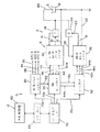
次に、本発明が、それに対して改良したものおよび/または性能を高めたものである上記バックグラウンドシステムについて説明し、図1は、交流電流を溶接ステーションWSにアークとして生成する単一のセルの形をとる単一の電気アーク溶接システムSを開示する。このシステムまたはセルは、電極Eおよび、パイプシームまたは他の溶接実施の形をとる被加工物Wとに直列な出力リード10、12を有する第1のマスター溶接機Aを含む。ホール効果電流変換器14は、溶接機Aの電流に比例してライン16に電圧を生成する。溶接パラメータなどのタイムクリティカルではないデータは、リモート中央制御部18で生成される。同様に、次のスレーブ溶接機Bは、追加的な交流電流を溶接ステーションWSへ向けるために、リード10、12に並列に接続されたリード20、22を含む。ホール効果電流変換器24は、溶接動作中の溶接器Bの電流レベルを表わすライン26に電圧を生成する。単一のスレーブまたはフォロワ溶接器Bが示されているが、どのような数の追加的な溶接器も、マスター溶接器Aに並列に接続して電極Eおよび被加工物Wの両端に交流電流を生成することができる。該交流電流は、極性スイッチング網の前ではなく上記溶接ステーションで合成される。各溶接器は、組み合わせたマスターコントローラおよび電源30として図示したようなコントローラとインバータをベースとした電源と、スレーブコントローラおよび電源32とを含む。コントローラ30、32は比較的低いレベルの論理ネットワークからパラメータデータおよび同期データを受け取る。パラメータ情報またはデータは、電源固有のものであり、それにより、該電源の各々は、電流、電圧および/またはワイヤ送給速度等の所望のパラメータを与えられる。低レベルのディジタルネットワークは、該パラメータ情報を供給することができるが、極性反転のための交流電流が同時に発生する。この「同時」は、10μs以下、好ましくは、1〜5μs程度の時間差を表わす。電源30および電源32からの交流出力の正確な調整を実現するためには、上記スイッチングポイントおよび極性情報は、上記タイミングがあまり正確ではない一般的な論理ネットワークから供給することはできない。個々の交流電源は、「ゲートウェイ」と呼ばれる高速、高精度のDC論理インタフェースによって調整される。図1に示すように、電源30、32は、両方向矢印42m、42sによって示す必要な作動パラメータを与えられる。この時間に敏感でない情報は、図1に示すディジタルネットワークによって供給される。マスター電源30は、一方向矢印40で示される同期信号を受けて、その交流出力電流のコントローラ動作のタイミングを図る。電源30に対する交流電流の極性は、矢印46で示すように出力される。マスター電源30の交流電流に対する実際のスイッチングコマンドは、ライン44に出力される。該スイッチングコマンドは、インバータの形態の電源Sに「キル」するように知らせ、これは電流の劇的な低減になる。別法として、これは、極性を反転させる実際のスイッチ信号である。上記「スイッチングポイント」またはライン44上のコマンドは、好ましくは、Stavaの米国特許第6,111,216号明細書に記載されているような「スイッチングポイント」を用いた「キル」および電流反転コマンドである。すなわち、タイミングが図られたスイッチングポイントまたはコマンドは、ライン44により電源30から出力される。これらのスイッチングポイントまたはコマンドは、低電流または単に電流反転ポイントにおけるスイッチレディ信号に伴う電源「キル」を含む。該スイッチ「レディ」は、どちらのインバータも、設定電流以下になるまで実際には反転しないので、「キル」コンセプトが実施された場合に使用される。このことは、図16に説明されている。コントローラ30のスイッチの極性は、ライン46上の論理を制御する。スレーブ電源32は、ライン44b上の該スイッチングポイントまたはコマンド論理と、ライン46b上の極性論理とを受け取る。これら2つの論理信号は、伝送ゲートウェイであるゲートウェイ50、およびライン44a、46a上の受信ゲートウェイであるゲートウェイ52として示す高精度論理インタフェースを介して、上記マスター電源とスレーブ電源との間に相互接続される。これらのゲートウェイは、上記電源の各々のためのネットワークインタフェースカードであるため、ライン44b、46b上の論理は、それぞれ、ライン44、46上の論理に近いタイミングが図られる。実際には、ネットワークインタフェースカードまたはゲートウェイ50、52は、この論理を、10μs以内、好ましくは1〜5μs以内で制御する。ゲートウェイまたはインタフェースカードによって設けられるように説明した低精度ネットワークは、ライン42m、42sを介した中央制御部18からのデータに対して個々の電源を制御する。これらのラインは、(中央制御部18等の)リモート領域からのデータを含み、該データは、時間に敏感ではなく、かつこのゲートウェイの正確な特性を用いない。スイッチ反転のタイミングを図るための高精度データは、ネットワークインタフェース50、52を介して論理信号を相互接続することを用いる。図1のシステムは、単一の交流アークのための単一のセルであるが、本発明は、2つまたはそれ以上の交流アークが、パイプ溶接時に見つかった大きなギャップを充填するために形成されるタンデム電極に限定されない。しかし、上記バックグラウンドシステムは、この用途のために示されている。すなわち、上記第1の電極のためのマスター電源30は、第1の電極、例えば、ARC1のためのシステムSのタイミングまたは位相操作を決める同期信号を受け取る。システムSは、同期出力84、86および88によってタイミングが図られるARC2、3および4を生成するために他の同一のシステムと共に使用される。このコンセプトは、図5に概略的に説明されている。同期または位相設定信号82〜88は、単一のタンデム電極と共に図1に示されている。中央制御コンピュータおよび/またはウェブサーバ60を備える情報ネットワークNは、タンデム動作において異なる電極を制御するいくつかのシステムまたはセルにおける特定の電源に関連するディジタル情報またはデータを提供する。インターネット情報62は、ローカル配線ライン70a、70b、70cを有するイーサネットネットワーク70の形をとるローカルエリアネットワークに向けられる。同様の配線ラインは、タンデム溶接動作のARC1、2、3および4を生成する4つのセルにおいて使用される各電源に向けられる。システムまたはセルSの説明は、他の電極におけるアークの各々にも当てはまる。交流電流を用いる場合には、マスター電源が使用される。ある場合には、単にマスター電源が、セル特定同期信号と共に使用される。高電流が必要な場合には、上記システムまたはセルは、図1のシステムSに関して説明したようなマスターおよびスレーブ電源の組合せを含む。ある場合には、直流アークは、ジェネレータ80によって同期される2つまたはそれ以上の交流アークと共に使用される。該直流アークは、2つまたはそれ以上の同期交流アークが続くタンデム電極溶接操作におけるリード電極である場合がある。直流電源は、同期する必要はなく、極性論理およびスイッチングポイントまたはコマンドの正確な相互接続の必要もない。いくつかの直流電源による電極は、正負間で切り替えてもよいが、交流駆動電極の周波数でではない。アークの生成に関係なく、イーサネットまたはローカルエリアネットワーク70は、タンデム溶接操作で用いられる様々なシステムの特定の電源のために指定された符号様式で識別されるパラメータ情報を含む。また、このネットワークは、いくつかのセルまたはシステムのための同期信号を用い、それにより該システムは、時間関係でずらすことができる。それらの同期信号は、復号されて、図1のライン40で示すマスター電源によって受信される。このようにして、上記交流アークは、時間基準でずれている。これらの同期信号は、ネットワークインタフェースカードまたはゲートウェイ50、52を通るスイッチングポイントほど正確である必要はない。上記データネットワーク上の同期信号は、可変パルスジェネレータ80の形をとるネットワークインタフェースによって受信される。該ジェネレータは、ライン84、86および88にオフセット同期信号を生成する。これらの同期信号は、タンデム動作における個々の電極に対する個別の交流電流セルの位相を指図する。同期信号は、インタフェース80によって生成することができ、あるいは、実際には、ネットワーク70を介して上記ジェネレータにより受信することができる。ネットワーク70は、単にジェネレータ80を作動させ、多数の同期信号に対する遅延パターンを生成する。また、ジェネレータ80は、該特徴が、タンデム溶接動作において必要であれば、該同期パルスの周波数によって個別のセルの周波数を変化させることができる。
The background system, to which the present invention is an improvement and / or performance enhancement, will now be described, wherein FIG. 1 illustrates a single cell that generates alternating current as an arc at the welding station WS. A single electric arc welding system S taking the form of The system or cell includes a first master welder A having output leads 10, 12 in series with an electrode E and a workpiece W in the form of a pipe seam or other welding implementation. The Hall effect
種々のコントローラおよび電源を、図1に記載したようなシステムを実施するために用いることができるが、該システムの好適な実施は、図2に記載されており、電源PSAは、コントローラおよび電源30と組み合わされており、電源PSBは、コントローラおよび電源32と組み合わされている。これら2つのユニットは、構造上本質的に同じであり、また、適切な場合、同じ符号が付けられている。電源PSAの説明は、電源PSBに同様に当てはまる。インバータ100は、3つの位相ライン電流L1、L2、およびL3を受信する入力整流器102を有する。出力変換器110は、出力整流器112を介して、反対極性のスイッチQ1、Q2を駆動するタップ付きインダクタ120に接続されている。電源PSAのコントローラ140aおよび電源PSBのコントローラ140bは、コントローラ140aがタイミング情報をコントローラ140bへ出力することを除いて、本質的に同じである。スイッチングポイントまたはライン142、144は、本願明細書に援用するStavaの米国特許第6,111,216号明細書に詳細に説明されているように、ライン142、144上の論理によって表わされる時間に極性を反転させる極性スイッチQ1、Q2の導通状態を制御する。該制御は、論理プロセッサを用いたディジタルであり、すなわち、A/Dコンバータ150は、フィードバックライン16またはライン26上の電流情報を、アナログ誤差増幅器として示されている誤差増幅器152からの出力のレベルに対する制御ディジタル値に変換する。実際には、これはディジタルシステムであり、該制御構造にはさらなるアナログ信号はない。しかし、図示したように、増幅器は、コンバータ150からの第1の入力152aと、コントローラ140aまたは140bからの第2の入力152bとを有する。ライン152b上の電流コマンド信号は、溶接ステーションWSにおけるアークの両端の交流電流に必要な波形形状または波形を含む。これは、本願明細書に援用するBlankenshipの米国特許第5,278,390号等のLincoln Electricのいくつかの特許によって教示されているような標準的な実施である。また、本願明細書に援用するStavaの米国特許第6,207,929号明細書も参照されたい。増幅器152からの出力は、発振器164によって制御される周波数でパルス幅変調器162を駆動するコンバータ160によってアナログ電圧信号に変換され、これは、プロセッサソフトウェアのタイマープログラムである。上記アークにおける波形の形状は、ライン152bにおける電圧値またはディジタル値である。発振器164の周波数は、18kHz以上である。このシステムの全体構造は、本発明の好適な実施の形態においてはディジタル化されており、アナログ信号への再変換を含んでいない。この説明は、説明のための概略的なものであり、本発明を実施する際に用いる電源の種類の限定を意図するものではない。他の電源も用いることができる。
Various controllers and power sources can be used to implement the system as described in FIG. 1, but a preferred implementation of the system is described in FIG. The power source PSB is combined with the controller and the
図1および図2の概念を用いたバックグラウンドシステムは、図3および図4に示されている。被加工物200は、それぞれ、別々の電源PS1、PS2、PS3によって作動されるタンデム電極202、204および206によって溶接されるパイプのシームである。該電源は、Houstonの米国特許第6,472,634号の技術に従って調整された1つ以上の電源を含むことが可能である。図示した実施の形態は、リード電極202に対する直流アークと、タンデム電極204、206の各々に対する交流アークとを含む。該タンデム電極の生成された波形は、交流電流であり、また、上述した波形技術に従った波形整形器または波形生成器によって生成された形状を含む。電極202、204および206が溶接経路WPに沿って移動すると、溶融金属溜まりPは、それぞれ電極202、204および206からの沈下212、214および216に続くオープンルート部210と共に、パイプシーム200に沈下する。上述したように、図15の波形によって後に説明する2つ以上の交流駆動電極は、隣接する電極の交流電流に関連する本発明によって作動させることができる。図4に示すような電源は、それぞれ、整流器222からの直流リンクを受け取るインバータ220を含む。Lincolnの波形技術に従って、チップまたは内部プログラムパルス幅変調器段224は、18kHz以上、好ましくは20kHz以上の周波数で発振器226によって駆動される。発振器226がパルス幅変調器224を駆動すると、その出力電流は、ライン242における電圧値またはディジタル値として、波形整形器240から出力された波形によって指図される形状を有する。出力リード217、218は、電極202、204および206と直列になっている。リアルタイムの形状は、ライン234上の出力が交流波形の形状を制御するように、比較器230として示す段によって、ホール効果変換器228からのライン232における実際のアーク電流と比較される。ライン234上のディジタル値または電圧は、該アークにおける電流の波形が、波形整形器240から出力された選択された特性に従うようにインバータ220を制御する、ライン224a上の出力信号を決定する。これは、上述したように、標準的なLincolnの波形技術である。電源PSIは、リード電極202に直流アークを生成し、そのため、この電源の波形整形器240からの出力は、該直流電流の振幅を示す定常状態にある。本発明は、直流アークの生成に関するものではない。反対に、本発明は、電極204、206等のタンデム電極に対する2つの隣接する交流アークにおける電流の制御である。本発明によれば、波形整形器240は、交流波形の所望の形状または特性を選定するのに用いられる入力250を含む。この形状は、シフトプログラム252として概略的に示す内部プログラミングによってリアルタイムでずらすことができる。波形整形器240は、ライン254上の優先信号である出力を有する。実際には、該優先信号は、図7に示すような論理ビットである。論理1は、波形整形器240によって生成された波形に対する負の極性を示し、論理0は、正の極性を示す。上記電源に向けられたこの論理信号またはビットコントローラ220は、図16に示した技術に従って読み出される。上記インバータは、ライン254上の論理ビットの変化によって始まる特定の「READY」時間に、正の極性から負の極性または反対極性に切り替わる。実際には、このビットは、図1および図5に示す可変パルスジェネレータ80から受信される。図3および図4に示すバックグラウンド溶接システムは、電極204および206における交流アーク電流の形状を用いて、有益な結果、例えば、概して静止した溶融金属溜まりPおよび/またはアーク溶接時に使用する変換器波形と適合性のある合成サイン波形を得る。図3および図4に示す電気アーク溶接システムは、波形整形器240のための「SELECT」プログラム250における波形を選定するためのプログラムを有する。固有の波形が、上記タンデム電極によって使用される。交流アークを生成する上記電源のうちの1つを図5に概略的に示す。該電源は、図1に示す可変パルスジェネレータ80によって制御される。該ジェネレータからの信号260は、上記第1のアークのための該電源を制御する。この信号は、波形の同期およびライン254上に波形整形器240によって出力された極性ビットを含む。ライン260a〜260nは、本発明の溶接システムによって作動される所望の後続のタンデム交流アークを制御する。これらの信号のタイミングは、他の波形の始動をずらす。図5は、単に、図4と共に説明したような連続的なアークを制御するための可変パルスジェネレータ80の関係を示す。
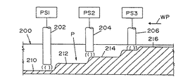
A background system using the concepts of FIGS. 1 and 2 is shown in FIGS. The
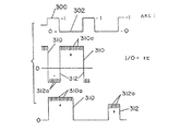
Houstonの米国特許第6,472,634号明細書の溶接システムにおいては、上記交流波形は、図6に示すように生成され、電極204におけるアークAC1のための波形整形器が、正の部分272および負の部分274を有する信号270を生成する。電極206における第2のアークAC2は、正の部分282および負の部分284を有する波形整形器からの信号280によって制御される。これら2つの信号は同じであるが、図6に示すように、ジェネレータ80からの信号によって距離xだけずらされる。上記アークのうちの1つに上記波形技術が生成した電流パルスは、図6の底部に示す正の部分290および負の部分292を有する波形である。上記波形整形器からの論理ビットは、該波形が、正の極性から負の極性および逆に切り替えられるときを決定する。(本願明細書に援用する)Stavaの米国特許第6,111,216号明細書の開示によれば、パルス幅変調器224は、通常、ポイント291aおよび291bにおける低レベルまでシフトされる。そして、電流は、固定レベル、例えば、100アンペアに達するまで低減される。従って、上記スイッチは、ポイント294aおよび294bにおいて極性を変化させる。このことは、電流が、正の部分290と負の部分292との間で変化するときに、垂直ラインまたは形状296a、296bを形成する。これは、Houstonの特許に開示されているシステムであり、同様の波形は、磁気的干渉を避けるためにずらされている。波形部分290、292は、アークAC1においておよびアークAC2において同じである。これは、上記溶融金属溜まりを制御するためおよび/または今まで用いられないような方法でサイン波形を合成するために、アークAC1およびアークAC2における波形をカスタマイズすることに関連する本発明とは異なる。図6の開示は、波形をシフトする概念を示すために記載されている。極性間の垂直変化を生成する同じスイッチング手順は、本発明の好適な実施の形態において用いられる。図6に示す溶接システムから不平衡波形への変換を図7に示す。ライン254上の論理は、部分300で論理1に、かつ部分302で論理0になるように示されている。該論理またはビット数の変化は、図16に示すシステムが極性をシフトする時間を知らせる。このことは、図6の下のグラフのポイント294a、294bに概略的に示されている。隣接する交流アークの各々のための波形整形器240は、一方の極性のための第1の波形整形器310と、他方の極性のための第2の波形整形器312とを有する。波形310、312の各々は、ライン254上の論理と共に得られるライン234上の論理によって生成される。すなわち、図7に示すようなパルス310、312は、正および負の極性部分が異なるパルスである。パルス310、312の各々は、図に示すような別々で種類が異なる電流パルス310a、312aによって生成される。極性間のスイッチングは、上記波形整形器によって生成された波形が、波形310、312の通常形状を有するように示されている図6に示すように実現される。正の極性は貫通を制御し、負の極性は沈下を制御する。波形の正のパルスと負のパルスとは異なり、スイッチングポイントは1つのアークにおける交流波形が、負の極性および正の極性の両方において制御されて、波形整形器240の出力によって生成された特定の形状を有するように制御される。図7に示す電流を有するアークに隣接するアークに対する波形は、図8に最も良く示す効果を得るために異ならせて制御される。アークAC1における波形は、図8の上部である。該波形は、電流パルス320aで示す正の部分320と、パルス322aによって形成される負の部分322とを有する。正の部分320は、最大の振幅aと幅または周期bとを有する。負の部分322は、最大の振幅dと時間または周期cとを有する。これら4つのパラメータは、波形整形器240によって調整される。図示の実施の形態において、アークAC2は、図8の底部に示す波形を有しており、正の部分330は、電流パルス330aによって形成され、かつ高さまたは振幅a’と時間長または周期b’とを有する。負の部分332は、パルス332aによって形成され、かつ最大の振幅d’と時間長c’とを有する。これらのパラメータは、波形整形器240によって調整される。本発明によれば、アークAC1に対する該波形整形器からの波形は、アークAC2に対する波形整形と位相が異なっている。該2つの波形は、(a)貫通および沈下が制御され、かつ(b)溜まりPが、その期間に、同じ極性または反対の極性の特定の極性関係になる長い時間がないように調整されるパラメータまたは大きさを有する。波形形状を形成する際のこのコンセプトは、図9および図10によって説明されるような長期の極性関係を防ぐ。図9において、電極204、206は、常に隣接する電流の波形によって決まる同じ極性を有する。その場合、電極204の磁束350および電極206の磁束352は、同じ方向であり、該電極間の中央領域354において互いに相殺する。このことは、溶融溜まりP内の電極204、206からの溶融金属部分360、362を、矢印cで示すように、共に移動させる。ごく短期間、例えば、20ms以内に終了しない場合、電極204間の溜まりP内の溶融金属のこの内方への移動または崩壊は、上方への噴出動作を最終的に引き起こすことになる。図10に示すように、該溜まりの対向する動きは、電極204、206が反対の極性を有する場合に起きる。そして、磁束370および磁束372は、上記電極間の中央部分374において蓄積され増加する。該電極間の大きな力は、溜まりPの溶融金属部分364、366を、互いに引っ込めるかあるいは互いに離れさせる。このことを矢印rで示す。溜まりP内の溶融金属の外方へのこのような作用は、10ms以下の実質的な時間継続する場合、溶接ビードの破裂を引き起こす。図9および10を見て分かるように、隣接する電極の波形の極性が、その間に同じになるかまたは反対の極性になる期間を限定するのが好ましい。図6に示すような波形は、同じ極性または反対の極性の特定の極性関係の長時間の同時発生を防ぐという目的を実現する。図8に示すように、同じ極性および反対の極性は、アークAC1およびアークAC2の周期長よりも非常に短い期間、保持される。上記正および負の領域に異なる形状および異なる振幅を有するパルスという新規なコンセプトを用いて、極性関係の長期の発生を防ぐというこのプラス指向の進化は協力して、一般的な変換器電源、またはLincolnの波形技術の一般的な利用を用いた溶接の際に、これまでは得られないような方法で、上記溜まりを制御し、貫通を制御し、かつ沈下を制御する。
In the welding system of Houston US Pat. No. 6,472,634, the AC waveform is generated as shown in FIG. 6, and the waveform shaper for arc AC1 at
図11において、波形整形器240からの交流波形の正および負の部分は、該波形の負の部分と比較して、異なるエネルギを正の部分に有する合成サイン波形状である。該合成サイン波または該波形のサイン波部分は、該波形を、変換器溶接回路と、およびサイン波溶接の評価と適合させることを可能にする。図11において、波形370は、アークAC1にあり、波形372はアークAC2にある。これらのタンデムアークは、図11に示す交流溶接電流を用い、小さな正のサイン波部分370aはアークAC1における貫通を制御し、より大きな負の部分370bは、アークAC1における金属の析出を制御する。図7で説明したように、論理ビットの変化に伴って、極性間にはスイッチングがある。サイン波形370は、垂直ライン370cで示すように、約100アンペアからゼロ電流を通って垂直に下降する。負の部分370bと正の部分370aとの間の移行は、垂直な移行370dを引き起こすスイッチングポイントにおける垂直方向の移行をスタートさせる。同様に、アークAC2の位相シフト波形372は、小さな貫通部分372aと、大きな負の沈下部分372bとを有する。極性間の移行は、垂直ライン372cおよび372dによって示す。波形372は、上記溜まりの力学が、隣接するアークAC1、AC2の極性によって引き起こされる該溜まり内の溶融金属の過剰な崩壊または反発を伴うことなく制御されるように、波形370に対してシフトされている。図11においては、サイン波形状は同じであり、かつ周波数は同じである。該波形は、単に、特定の極性関係の長期の発生を防ぐためにシフトされている。
In FIG. 11, the positive and negative portions of the AC waveform from the
図12において、波形380は、アークAC1のために用いられ、波形382は、アークAC2のために用いられる。部分380a、380b、382aおよび382bは、サイン波合成されており、かつ同じ振幅からなるように図示されている。これら2つの波形を90°ずらすことにより、同時発生の極性の領域は、領域390、392、394および396として識別される。サイン波特性を有する該シフト波形を用いることにより、同じ極性または反対の極性は、長い間残らない。従って、上記溶融金属溜まりは、かきまわされず、かつ静止したままである。この効果は、所定の波形の正および負の極性部分の間のエネルギの違いというコンセプトも組み合わせる本発明を用いることによって得られる。図12は、同時発生の極性関係の定義、および該関係は極短期間しか残らないということを本質的に示す。この目的を実現するため、本発明の別の実施の形態を図13に示し、以前に定義した波形380は、アークAC2(a)の鋸波状波形として示す波形400、またはアークAC2(b)に対する波形として示すパルス状波形402と結合される。波形380を、異なる波形402の異なる波形400と結合すると、同時発生の極性関係の非常に小さな領域または期間410、412、414等が生じる。図14においては、一方のアークで生成された交流波形は、他方のアークで生成された交流波形と、非常に異なる。本発明における用途のための非常に異なる波形というこの同じ概念を図14に示し、波形420は、交流パルス特性波形であり、波形430は、波形420の約半分の期間を有するサイン波特性波形である。波形420は、小さな貫通した正の部分420aと、直線極性移行部420cを有する大きな沈下部分420bとを含む。波形430は、正の部分430aと、垂直極性移行部430cを有する負の部分430bとを含む。これら2つの異なる波形を有することにより、上記両合成サイン波コンセプトは、1つの電極に対して用いられ、かつ長期の同時発生の極性関係はない。すなわち、溜まりP内の溶融金属は、両アークAC1、AC2による溶接動作の間、ほぼ静止したままである。
In FIG. 12,
図15において、波形450、452、454および456は、4つのタンデムアーク、すなわちアークAC1、アークAC2、アークAC3およびアークAC4の各々のための電源の波形整形器240によって生成される。隣接するアークは、該波形がいつ、対応して、負の部分から正の部分へ移行するかを定義する合成信号460によって示すように整列される。この合成信号は、スタートパルスが整列されていることを除いて、図1に示すジェネレータ80によって生成される。本発明のこの実施形態においては、第1の波形450は、隣接する波形452、454および456の正および負の部分と同期される正の部分450aを有する。例えば、正の部分450aは、波形452の正の部分452aおよび負の部分452bと同期されかつ相互に関連付けられる。同様に、波形452の正の部分452aは、波形454の正の部分454aおよび負の部分454bと同期されかつ相互に関連付けられる。同様の関係は、正の部分454aと、波形456の部分456a、456bとの間に存在する。負の部分450bは、整列された波形452の2つの反対極性部分と同期されかつ相互に関連付けられる。同じタイミング関係は、負の部分452bと波形454との間に存在する。換言すれば、各隣接するアークにおいて、波形の一方の極性部分は、隣接するアークの全体の波形と相互に関連付けられる。このようにして、図9および図10に関連して説明したように、溜まりPの崩壊および反発力は、力学的に制御される。1つまたはそれ以上の正または負の部分は、図11および12で開示した波形に関連して説明したような合成サイン波とすることができる。
In FIG. 15,
図1および図2に示すように、上記スイッチのマスターコントローラを切り替えると、スイッチコマンドが、電源30のマスターコントローラ140aに対して発行される。このことは、「キル」信号を該マスターによって受信させるため、キル信号および極性論理が、単一の電極と並列に接続された1つまたはそれ以上のスレーブ電源のコントローラへ直ちに伝送される。標準的な交流電源を、上記極性スイッチと並列の大きな緩衝器と共に使用した場合、該スレーブコントローラまたはコントローラは、該マスター電源が該スイッチコマンドを受信した後、直ちに1〜10μs以内に切り替えられる。これは、高精度のインタフェースカードまたはゲートウェイの効果である。実際に、上記並列接続された電源の電流反転のための実際のスイッチングは、出力電流が、所定値、例えば、約100アンペア以下になるまで発生しない。これにより、より小さなスイッチの使用が可能になる。
As shown in FIGS. 1 and 2, when the master controller of the switch is switched, a switch command is issued to the master controller 140 a of the
単一の交流アークのための全ての電源に対するスイッチングの実施は、実際のスイッチングを、全ての電源が所定の低電流レベル以下になった後にのみ行うことができる遅延スイッチング技術を用いる。該遅延プロセスは、ディジタルプロセッサのソフトウェアで実現され、かつ図16の概略レイアウトによって説明される。マスター電源500のコントローラが、ライン502で表わされるコマンド信号を受信すると、該電源は、スイッチングシーケンスをスタートさせる。該マスターは、該マスターの極性スイッチングに対応する該スレーブのスイッチングのための所望の極性を実現するために、ライン504上に論理を出力する。命令されたスイッチシーケンスにおいて、マスター電源500のインバータは、ターンオフまたはダウンされるため、電極Eへの電流は、ホール効果変換器510によって読み出されるように減少する。ライン502のスイッチコマンドは、ホール効果変換器532、534によって測定されるように電流を接点530に供給する並列接続されたスレーブ電源520、522のコントローラに、ライン512で示される即時の「キル」信号を生じる。全ての電源は、インバータをターンオフまたはダウンさせた状態で、スイッチシーケンス状態にある。ソフトウェア比較回路550、552、554は、減少した電流を、ライン556上の電圧によって参照される所定の低電流と比較する。各電源が所定値以下に減少すると、ライン560、562および564に信号が発生して、それぞれサンプル・ホールド回路570、572および574の入力に送られる。該回路は、上記電源の各々からのライン580のストロボ信号によって出力される。設定論理が回路570、572および574に格納されている場合、YES論理が、該ストロボ信号発生時に、ラインREADY1、READY2およびREADY3上に発生する。この信号は、上記電源内で生成され、25μsの周期を有するが、他の高速ストロボを使用することができる。該信号は、図16に点線で示すマスター電源のコントローラCに向けられる。ANDゲート584で示されるソフトウェアのAND機能は、全ての電源が極性を切り替える準備ができている場合に、ライン582上にYES論理を出力させる。この出力条件は、ライン504上に発生したときに切り替えられる極性の所望の論理を備えるそのD端子を有するソフトウェアのフリップフロップ600のクロックイネーブル端子ECLKに向けられる。約1MHzで作動される発振器またはタイマーは、端子CKへのライン602上の信号によってフリップフロップをクロックする。このことは、ライン612上の同一の論理がマスター電源500を切り替えると同時に、ライン504上の極性コマンド論理をQ端子604へ伝送して、この論理をライン610に生成してスレーブ520、522を切り替える。スイッチング後、ライン504上の極性論理は、反対極性にシフトされ、マスター電源は、スイッチング周波数に基づいて次のスイッチコマンドを待つ。他の回路を、スイッチングシーケンスにおける遅延に影響を及ぼすのに用いることができるが、図16の説明は現在のスキームである。
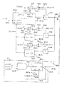
The implementation of switching for all power supplies for a single AC arc uses a delayed switching technique that allows actual switching to occur only after all power supplies are below a predetermined low current level. The delay process is implemented in digital processor software and is illustrated by the schematic layout of FIG. When the controller of
図1〜図16でこれまで説明したように、その他の有利な特徴を実現するための溶接機および該溶接機のための制御システムは、背景情報として提示されている。この説明は、本発明に対する従来技術ではなく、バックグラウンドを説明する。この背景技術は、本発明の譲受人であるLincoln Electric Companyによって開発されてきた。この背景説明は、必ずしも従来技術ではないが、図17に示す溶接機によって実現されるような、そのような波形技術溶接機における特定の改良の説明のために提示されている。この溶接機は、溶接プロセスに用いられる波形の厳密な特徴を描く。すなわち、正確な波形は、プログラム700の使用によって得られる。この波形は、特定の有芯電極を用いて調整される。
As previously described in FIGS. 1-16, a welder for realizing other advantageous features and a control system for the welder are presented as background information. This description describes the background rather than the prior art for the present invention. This background art has been developed by the Lincoln Electric Company, the assignee of the present invention. This background description is not necessarily prior art, but is presented for the purpose of describing certain improvements in such a corrugated technology welder, such as that realized by the welder shown in FIG. This welder draws the exact characteristics of the waveforms used in the welding process. That is, an accurate waveform is obtained by using the
図4および図5に示すような溶接機および/または溶接システムは、図19および図20に示す特定の有芯電極との使用のための所定の波形の正確な特性を厳密に設定するのに使用される制御プログラム700によって作動する。プログラム700を図17に示し、溶接機Wは、選択ネットワーク250によって一般的なタイプの溶接波形に設定された波形整形器240を有する。選択された波形は、連続する波形によって所定の溶接プロセスを実行する所望の交流波形である。この波形は、本発明に従って、特定の有芯電極に対して用いられるように設定される。波形制御プログラム700は、波形の厳密な所望の特性を設定する特性制御ネットワーク710と、所定の有芯電極に用いられる設定特性を実質的に変更することなく、該波形のエネルギまたは出力を調節する振幅制御回路712とを有する。この特定の特性は、対応する電極が該溶接プロセスに使用される場合に用いるために、図21および図28に開示した溶接機に記憶されている。
A welder and / or welding system as shown in FIGS. 4 and 5 can be used to precisely set the exact characteristics of a given waveform for use with the particular cored electrode shown in FIGS. Operated by the
プログラムまたは制御ネットワーク700は、交流溶接プロセスを構成する連続的な波形の各個別の波形の厳密な通常特性を制御する波形整形器240に接続されている。該波形の通常特性の厳密かつ正確な相乗的設定というこの目的を実現するために、4つの別々の特性パラメータが個々に調節される。第1のパラメータは、インタフェースネットワーク722によって手動または自動で調節される回路720によって波形特性に設定されて、ライン724で示す出力上に設定値を生成する周波数である。この値は、波形特性の設定周波数を制御する。当然、これは、正確な波形の周期である。同様にして、該波形のデューティサイクルは、調節可能なインタフェースネットワーク732と、正の半周期と負の半周期との関係を制御する値を生成する出力ライン734とを有する回路730によって制御される。この特性パラメータは、回路730からの論理またはデータによって設定される。ライン724上の信号またはデータ、およびライン734上のデータにより、該波形の交流特性が設定される。このことは、波形の個々の部分のエネルギレベルには関係なく、単に、該波形の通常の所定の特性に関係する。該波形の増加率を制御するために、手動または自動調節ネットワーク742を有する回路742と、波形の設定特性が負から正極性に変化する率を設定する、ライン744上の出力信号とが設けられている。同様にして、減少回路750は、調節インタフェース752と出力ライン754とを備えている。ライン724、734、744および754上の値の大きさは、個々の波形の特性を設定する。これらのパラメータ特性のうちの少なくとも2つは、一緒に設定されるが、好ましくは、波形特性を決めるために、全ての特性パラメータが設定される。
The program or
上記溶接プロセスにおいて、各個別の波形によって伝送されるエネルギまたは出力のための該波形の特性を制御するために、プログラム700は、2つの個々の部分760、762に分けられる振幅回路またはネットワーク712を含む。該振幅回路のそれらの部分は、特性制御ネットワーク710によって設定された通常の特性に実質的に影響を及ぼすことなく、各極性の間に、該波形のエネルギまたは他の出力関連レベルを制御する。部分760は、インタフェースネットワーク772によって手動で調節されて、ライン774上の入力値とライン776上の出力値との関係を制御するレベル制御回路770を含む。レベル制御回路770は、本質的には、生成された設定波形特性の正の部分の間に、電流、電圧および/または電力を制御するディジタル誤差増幅器回路である。セレクタ250aは、回路770を、電流、電圧または電力モードのいずれかにシフトする。部分760は、ネットワーク710によって設定された通常特性を変化させながら、該波形の正の部分の間に、エネルギ、または電力あるいは他の熱レベルを制御する。同様に、第2の部分762は、入力ライン784上の値が、出力ライン786上のレベルまたは信号を制御するように、ネットワーク782によって設定または調節されるディジタル誤差増幅回路760を有する。従って、ライン776および786上のディジタルレベルデータは、特性制御ネットワーク710によって設定される各半周期の間に、電流、電圧および/または電力を制御する。
To control the characteristics of the waveform for energy or output transmitted by each individual waveform in the welding process, the
プログラム700の別の特徴によれば、波形整形器240は、振幅制御回路712のみによって制御され、該特性は、図4および図5に示すバックグラウンドシステムに用いられるネットワークまたはプログラム250によって設定される。ネットワーク250は、該特性を設定しないが、図21および図28の開示によって説明されるような公知のタイプの波形を選択する。プログラム700の高められた利点は、回路720、730、740を振幅回路770、780と共に用いて全ての特性パラメータを設定することによって実現される。当然、それらの回路のうちのいずれか1つによって制御される波形は、背景技術に優る改良である。プログラム700は、該波形が特定の有芯電極に対応するように、交流波形の各極性の間に、全ての特性パラメータおよび振幅の値を相乗的に調節する。
According to another feature of
プログラム700の動作を説明するために、2つの波形が図18に概略的に示されている。波形800は、正の部分802と負の部分804とを有し、両方共、一連の急速に生成された電流パルス800aによって生成される。波形800は、該波形の周波数または周期の制御と、正の部分802と負の部分804との比を説明するために、単に方形波として図示されている。これらのパラメータは、これまで単にネットワーク450によって選択されていた波形の種類を変更するように、プログラム700を用いて厳密に設定される。該波形のこの概略的な描写において、上記増加率および減少率は、本質的にゼロである。当然、Stavaの米国特許第6,111,216号明細書に教示されたスイッチングコンセプトは、Stavaの特許に記載されている効果を得るために、正と負の波形部分の間でシフトするのに用いられる。図示の第2の波形810は、周波数fと、正の部分812と、負の部分814とを有する。この図において、増加率816は、減少率818とは無関係に制御される。それらの変化率は、極性間のシフト中の波形の立ち上がりエッジおよび立ち下がりエッジにあることを示す矢印として示されている。プログラム700は、回路720、730、740および750によって、個別の波形の厳密な特性を物理的に設定することに関連する。該波形のいくつかのパラメータは、該波形を本質的に所望の特性に描くように調節される。交流波形のための通常設定特性を用いた非常に厳密な溶接プロセスは、プログラム700を用いた波形技術制御溶接機によって実行される。このプログラムは、交流波形と、溶接プロセスに用いられる電極とが適合するように、各個別の有芯電極のための波形を描くのに用いられる。
To illustrate the operation of
図17のプログラム700は、図19および図20に示す電極910等の個別に識別される有芯電極の各々のために最適化されかつ特別に調節される交流波形を構成または生成するのに用いられる。溶接機900は、電極910を被加工物WPの方へ向けるトーチ902を有する。アークACは、電極910の端部と被加工物WPとの間に生成される。該電極は、シース912と内部充填コア914とを有する有芯電極である。該コアは、パーティクル914aで表わされるようなフラックス材料を含む。これらの材料914aの目的は、(a)溶融金属をスラグでカバーすることにより、大気中の汚染物質から該溶融溶接金属をシールドすること、(b)溶接品質に対する有害な影響が最少化されるように、何らかの大気中の汚染物と化学的に結合させることおよび/または(c)アークシールドガスを生成することである。標準的な実施によれば、コア914は、パーティクル914bと呼ばれる合金材料と共に、コア914の充填物を与えるために組み合わされる他の種々のパーティクル914cを含む。溶接動作を最適化するためには、外部シールドガスと共に固体ワイヤを使用する必要があった。しかし、特定の物理学的および冶金学的特性を有する溶接を産み出すためには、特定の合金が必要であり、これは、固体ワイヤの形態で得るのが困難である。外部シールドガスを要する溶接プロセスを用いた場合、汚染は、防ぐのが困難である。そのため、環境が溶接に影響を及ぼさないように、自己シールド有芯電極を用いるのが有利となるであろう。有芯電極を用いた場合、上記シースおよびコアに対するバーンバック速度は異なる。これらの全ての困難性は、ほとんどのパイプライン溶接を、固体ワイヤおよび外部シールドガスを用いて行うことにつながった。これらの問題を克服するために、オハイオ州クリーブランドのLincoln Electric Companyによって、パイプ溶接での用途のためのSTT溶接が開発された。そのような溶接は、表面張力が溶融金属に伝わる短絡回路プロセスを用いる。このプロセスは、特に、オープンルート溶接中の溶接プロセスの熱を下げる。交流電源および有芯電極を用いた溶接の利点は、溶接波形が、特定の有芯電極に対して最適化されていなかったため、得ることができなかった。本発明は、図17に示すプログラム700等のプログラムを用いることにより、それらの困難を克服するため、厳密な交流波形が溶接動作のために生成されて、特に、所定の有芯電極と関連付けられる。所定の有芯電極によって調節される交流溶接動作のために、厳密にプロファイルしたまたは整形した波形を生成することにより、溶接動作が最適化される。今では、正確にプロファイルされた波形を用いて交流溶接動作を利用して、特定の有芯電極に適応させることが可能である。
The
有芯電極を使用して交流溶接動作を実行する溶接機900は、本発明に従って構成されているため、該溶接動作は、特定の電極に対して最適化される。溶接機900の詳細を図21に示し、電源920は、整流器920aによって駆動される。電極910は、シース912およびコア914を有する有芯電極である。溶接機900の電源920は、ライン924に電極識別信号を生成して、溶接プロセスに使用される特定の電極910を識別する記憶装置、ユニットまたは回路922を有する。読取り装置921は、図21の上部に示すような該読取り装置を通る特定の電極910を識別する。すなわち、ライン924の信号が電極910を識別する。装置921aは、どの特定の電極910が使用されているかを読取り装置921に手で伝える。換言すれば、読取り装置921は、溶接動作に使用される特定の有芯電極に対して設定される。この装置は、特定の電極を示すように手で調節される。電極910は、バーコードまたは他の読取り技術を用いて、記憶装置922によって識別することができる。バーコードは、電極ワイヤ910を含むスプールまたはドラム上に配置される。換言すれば、装置921は、ワイヤまたは電極910の識別を自動で感知するか、あるいは、手動入力を受取って、ブロック921aで示すように、該電極を示す。ライン921bの信号は、記憶装置922に向けられて、そこで、データ形式の信号は、溶接機900によって使用される全ての電極のために蓄積される。ライン921b上の信号は、特定の有芯電極に対応する、記憶装置922内の特定のデータを扱う。このデータは、特性信号をライン924に印加させる。この信号は、波形ルックアップ装置926を起動させるため、該装置は、ライン928に特性信号を出力する。この信号は、選択回路250に、特定の有芯電極のために、プログラム700によって生成されている特定の蓄積された特性を選択するように指示する。図17に示すプログラム700は、該蓄積された波形を特定の電極に対して調整する。電源920の残りは、すでに説明してある。ライン928の特性信号は、回路250に関連するメモリに格納された特定構成または生成の波形を選択する。特定の有芯電極910の特定構造または構成に対して調整された交流溶接波形は、ライン242に出力される。代替例によれば、ライン928の特定の信号は、上記電極およびワイヤ送給速度によって決まる。装置930は、ライン932に出力される設定値を有する。従って、ライン924および932上の論理またはデータは、ライン928の特性選択信号を決定する。波形ジェネレータ250のメモリ内の所望の蓄積された特性が用いられる。この特性は、特定の電極および/または特定の設定値ワイヤ送給速度に基づいている。典型的な構成された交流波形を図22に示し、プロセス曲線950は、正の部分952と負の部分954とを備える一連の波形を含む。本発明によれば、該波形は、18kHzよりもかなり大きいレートで生成され、かつパルス幅変調器224の出力ライン224aで生成された多数の個々のパルス960によって生成されている。これは、高速スイッチングインバータを制御する。本発明の好適な実施形態においては、曲線950は、正の振幅xと、zになるように示されている負の部分954の長さを有する負の振幅yとを有する。溶接動作における熱を制御するため、デューティサイクルzは、図22に示す波形が、特定の有芯電極に対して構成されている場合に調節される。図22の負の部分954は、上記被加工物に対する全体の熱入力を制御する。正の部分952は、上記電極に対しては熱に寄与し、かつ上記被加工物に対しては熱にあまり寄与しない。そのため、デューティサイクルを変化させることにより、該被加工物への全体の熱を変化させ、かつ制御することができる。本発明において、交流溶接プロセスは、波形整形器または波形ジェネレータ240の出力において生成される。選択された波形は、特定の有芯電極910に対するその利用を最適化するように厳密に調整される。溶接動作における熱を制御するため、該波形は、プログラム700によって制御されたデューティサイクルzを有する。該波形が調整された後、該波形は、選択回路250からの論理に基づいて、波形ジェネレータ240に設定される。溶接機900は、特定の交流波形を特定の有芯電極と関連付けて、構成形成電極910によって決まる溶接プロセスの動作を調整する。
Since a
本発明を実施する際に用いられる波形は、好ましくは、図22に示すような方形波であるが、初期加熱を制御するためには、該波形は本発明の範囲内であり、プロセス曲線970が、各々が正の部分972および負の部分974を有する波形を備える、図23に示す非方形波交流波形を使用できる。それらの部分の各々は、図22の曲線950に関して説明したような複数の個々のパルス960によって形成されている。これらの個々のパルス960は、18kHz以上の周波数で生成され、かつインバータ型電源で一般的に用いられる波形技術パルスである。加熱の割合を低減するため、部分972、974は、増加部分976、977、978および979を備えている。本発明を用いた交流溶接を最適化するために、その他の特性も可能である。
The waveform used in practicing the present invention is preferably a square wave as shown in FIG. 22, but for controlling initial heating, the waveform is within the scope of the present invention and the
本発明を実施することなく有芯電極を用いた場合に生じる問題を図24に示す。該溶接プロセスは、シース912を溶融して、溶融した上端部982で示すように、該電極の上方周囲に溶融した溶融金属980からなる部分を生成する。すなわち、該電極のシースは、該コアよりも早く溶融する。このことは、溶融金属材料を、保護ガス、または、コア914の内部構成物の溶融によって起きる化学的反応を要することなく、電極910の出力端部に存在させる。従って、アークACは、保護されていない大気中において、電極910の金属を溶融する。該溶融金属に必要なシールドは、上記シースおよびコアが、同じ速度で溶融した場合に形成される。溶融金属をコアよりも早く溶融させるという問題を、さらに、図25の描写図で示す。シース912からの溶融金属990は、該コアが溶融する機会を有する前に、すでに被加工物WPに結合している。これは、溶接プロセスに必要なシールドを与えることができない。図24および図25は、なぜ、有芯電極を使用した交流溶接が、沖合のパイプライン溶接や他のパイプライン溶接に用いられてこなかったかの理由を示している。
FIG. 24 shows a problem that occurs when a cored electrode is used without implementing the present invention. The welding process melts the
本発明は、有芯電極を使用したときの熱入力を制御する手段として、上述したような交流波形の利用を提案する。
本発明を用いることにより、溶接プロセスに用いる交流波形のための厳密な特性が選択され、それにより、シース912およびコア914は、略同じ速度で溶融する。上記シールドの溶融を、上記コアの溶融に対して適切に調整することに対しての失敗は、パイプライン溶接に対して、有芯電極を用いた交流溶接の利用を拒絶する理由になる。本発明の利点は、外部シールドガスを必要としないプロセスである。これが発生した場合、シールドガスSGおよび他のシールド構成要素は、シース912から溶融金属より早く生成される。本発明を用いることにより、この特徴は、プログラム700を用いて、溶接動作のための波形を厳密にプロファイルすることによって得ることができる。従来、そのような調整は可能ではなかった。プログラム700または同様のプログラムの発明が、本発明を可能にした。それらのプログラムは、個々の有芯電極に対して明確に調整されている波形を生成して、該有芯電極を、溶接動作中に、溶融金属を大気の汚染に対して保護するように、交流溶接プロセスに用いることができるようにする。
The present invention proposes the use of the AC waveform as described above as means for controlling the heat input when using a cored electrode.
By using the present invention, the exact characteristics for the AC waveform used in the welding process are selected so that the
有芯電極を用いて溶接する場合、上記シースおよびコアを同じ速度で溶融させることが好ましい。この作用は、コア材と外部シースとの同質混合を促進し、その結果、溶融材の混合が、大気汚染の影響に化学的に抗する。所望の溶接金属の物理学的および冶金学的特性をもたらすのに必要な合金成分は、該溶接金属内に均一に配分される。また、スラグおよび/またはガス構成組成物から得られる保護的恩恵が最適化される。この状況を図27に示す。対照的に、図26は、上記シースが、上記コアよりも早く溶融している状況を示す。シース912からの溶融金属990は、コア914が溶融する機会を有する前に、すでに、被加工物WPに結合している。金属990は、溶融していないコア組成物が実際に溶融している場合になる程度まで、大気汚染の影響から保護されていない。また、所望の物理学的および冶金学的特性を実現するのに必要な合金成分は、溶融金属990になくてもよい。
When welding using a cored electrode, it is preferable to melt the sheath and the core at the same speed. This action promotes homogeneous mixing of the core material and the outer sheath, so that the mixing of the molten material chemically resists the effects of air pollution. The alloy components necessary to provide the desired physical and metallurgical properties of the weld metal are evenly distributed within the weld metal. Also, the protective benefits obtained from the slag and / or gas component composition are optimized. This situation is shown in FIG. In contrast, FIG. 26 shows a situation where the sheath is melting faster than the core. The
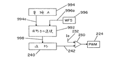
本発明の代替例を図27に示し、選択回路992は、ブロック994からライン994aへのデータに従って、波形Bを選択する。このブロックは、特定の電極Aを識別するデータを有する。該電極は、選択回路992の波形Bによって適応される構成を有する。ワイヤ送給速度ブロック996からのライン996aの設定値は、波形Bが、本発明の主たる態様である電極、すなわち、特定の設定値を有する電極Aのための波形となるように、波形Bを選択するのに用いられる。このことは、波形ジェネレータ240の出力を調整して、ブロック994によって識別される的確な有芯電極Aに対して調整される交流溶接プロセスの波形を制御する。電極Aは、波形Bを起動するのに用いられる。
An alternative example of the present invention is shown in FIG. 27, where the
本発明の基本的な態様は、特定の有芯電極を使用した場合に、所望の動作を実行する波形の生成である。該特定の有芯電極を識別し、その調整された交流波形を起動することにより、該電極と被加工物との間で、所望の溶接プロセスが実行される。本発明を実行するには、様々なアナログおよびディジタルコンポーネントが可能である。上記コアの構成および上記シースのサイズは、交流溶接プロセスに用いる最適な波形特性を決める。本発明は、波形技術を用いるタイプの電気アーク溶接プロセスに用いる波形の特性を正確に設定しかつ変更する、図17のプログラム700のようなプログラムによって可能である。
A basic aspect of the present invention is the generation of a waveform that performs a desired operation when a specific cored electrode is used. By identifying the particular cored electrode and activating its adjusted AC waveform, a desired welding process is performed between the electrode and the workpiece. Various analog and digital components are possible to implement the present invention. The configuration of the core and the size of the sheath determine the optimal waveform characteristics used in the AC welding process. The present invention is possible by a program, such as
220 インバータ
222 整流器
224 パルス幅変調器
240 波形整形器
900 溶接機
910 電極
912 シース
914 コア
920 電源
220
Claims (22)
前記一連の波形において、個々の波形を生成するための高周波スイッチングデバイスであって、各波形が、少なくとも18kHzの周波数で生成される多数の短絡電流パルスの各々の振幅によって形成される特性を有し、前記特性が、前記短絡電流パルスを制御する波形整形器に対する入力信号によって決定される高周波スイッチングデバイスと、
前記電極のタイプを示す特性信号を生成する回路と、
前記特性信号に基づいて前記入力信号を選択する選択回路とからなり、
これにより、前記波形整形器が、前記電源に、前記特定のタイプの有芯電極のための波形特性を生成させるように構成したことを特徴とする電気アーク溶接機。 In an electric arc welder adapted to generate a welding process with a series of alternating current waveforms by a power source between a work piece and a particular type of cored electrode having a sheath and a core,
A high-frequency switching device for generating individual waveforms in the series of waveforms, each waveform having a characteristic formed by the amplitude of each of a number of short-circuit current pulses generated at a frequency of at least 18 kHz. A high-frequency switching device whose characteristics are determined by an input signal to a waveform shaper that controls the short-circuit current pulse;
A circuit for generating a characteristic signal indicating the type of the electrode;
A selection circuit that selects the input signal based on the characteristic signal;
Thereby, the waveform shaper is configured to cause the power source to generate waveform characteristics for the specific type of cored electrode.
(a)前記特定の電極を用いた溶接のために調整された特定の特性を有する波形を選択する工程と、
(b)一連の選択された波形を生成して、溶接プロセスを生成する工程と、
(c)前記溶接プロセスを用いて前記電極により溶接を行う工程と、
を含むことを特徴とする溶接方法。 A method of welding to a workpiece using a specific cored electrode having a sheath and a core,
(A) selecting a waveform having specific characteristics adjusted for welding using the specific electrode;
(B) generating a series of selected waveforms to generate a welding process;
(C) welding with the electrode using the welding process;
The welding method characterized by including.
前記一連の波形において、個々の波形を生成するための高周波スイッチングデバイスであって、各波形が、パルス幅変調器により少なくとも18kHzの周波数で生成される多数の短絡電流パルスの各々の振幅によって形成される特性を有し、前記パルス幅変調器は、波形整形器によって制御される電流パルスの振幅で制御され、前記個々の波形のいずれかの部分の極性は、極性信号のデータによって決定される高周波スイッチングデバイスと、
個々の波形の1つ以上の特性パラメータを設定することにより、個々の波形の特性を決定する特性制御ネットワークであって、前記パラメータが、周波数、デューティサイクル、増加速度および減少速度からなる群から選択される特性制御ネットワークと、
前記固定された特性に影響を及ぼすことなく、前記個々の波形を調整するために、総電流、電圧及び/又は出力を設定するための振幅回路と、
を備えることを特徴とする電気アーク溶接機。 In an electric arc welding machine that generates a series of AC waveforms by a power source between a cored electrode and a workpiece,
In the series of waveforms, a high-frequency switching device for generating individual waveforms, each waveform being formed by the amplitude of each of a number of short circuit current pulses generated at a frequency of at least 18 kHz by a pulse width modulator. The pulse width modulator is controlled by the amplitude of the current pulse controlled by the waveform shaper, and the polarity of any part of the individual waveforms is determined by the data of the polarity signal. A switching device;
A characteristic control network that determines the characteristics of an individual waveform by setting one or more characteristic parameters of the individual waveform, wherein the parameter is selected from the group consisting of frequency, duty cycle, increasing rate, and decreasing rate A characteristic control network,
An amplitude circuit for setting the total current, voltage and / or output to adjust the individual waveforms without affecting the fixed characteristics;
An electric arc welding machine comprising:
前記電気アーク溶接機は、
前記一連の波形において、個々の波形を生成するための高周波スイッチングデバイスであって、各波形が、パルス幅変調器により少なくとも18kHzの周波数で生成された多数の短絡電流パルスの各々の振幅によって決定される特性を有し、前記パルス幅変調器は、波形整形器によって制御される前記電流パルスの振幅で制御される高周波スイッチングデバイスを備え、前記方法は、
(a)極性信号のデータによって、前記個々の波形のいずれかの部分の極性を決定する工程と、
(b)個々の波形の1つ以上の特性パラメータを設定することにより、個々の波形の特性を設定する工程であって、前記パラメータが、周波数、デューティサイクル、増加速度および減少速度からなる群から選択される工程と、
(c)前記特性を変化させることなく前記波形特性を調整し、電流、電圧および/又は出力の大きさを設定する工程と、
を含むことを特徴とする溶接方法。 In a welding method of an electric arc welding machine that generates a welding process with a series of alternating current waveforms by a power source between a cored electrode and a workpiece,
The electric arc welder is
In the series of waveforms, a high frequency switching device for generating individual waveforms, each waveform being determined by the amplitude of each of a number of short circuit current pulses generated at a frequency of at least 18 kHz by a pulse width modulator. The pulse width modulator comprises a high frequency switching device controlled by the amplitude of the current pulse controlled by a waveform shaper, the method comprising:
(A) determining the polarity of any part of the individual waveforms according to the polarity signal data;
(B) setting the characteristics of the individual waveforms by setting one or more characteristic parameters of the individual waveforms, wherein the parameters are from the group consisting of frequency, duty cycle, increasing rate and decreasing rate. Selected processes; and
(C) adjusting the waveform characteristics without changing the characteristics and setting the current, voltage and / or output magnitude;
The welding method characterized by including.
前記一連の波形において、個々の波形を生成するための高周波スイッチングデバイスであって、各波形が、少なくとも18kHzの周波数で生成された多数の短絡電流パルスの各々の振幅によって形成される特性を有し、前記特性は、前記短絡電流パルスを制御する波形整形器に対する入力信号によって決定される高周波スイッチングデバイスと、
特定の有芯電極を表わすいくつかのアドレスで読み出せるデータブロックを格納した電極記憶デバイスと、
所定の波形特性を前記波形整形器に設定するための、多数の記憶された波形信号を有する選択デバイスと、
前記特定の有芯電極のためのアドレスを選択したときに、特定のデータブロックを出力して所定の波形信号を選択する回路と、
で構成したことを特徴とする電気アーク溶接機。 In an electric arc welder adapted to generate a welding process with a series of alternating current waveforms by a power source between a work piece and a particular type of cored electrode having a sheath and a core,
A high-frequency switching device for generating individual waveforms in the series of waveforms, each waveform having a characteristic formed by the amplitude of each of a number of short-circuit current pulses generated at a frequency of at least 18 kHz. The characteristic is determined by an input signal to a waveform shaper that controls the short circuit current pulse; and
An electrode storage device storing data blocks that can be read at several addresses representing a particular cored electrode;
A selection device having a number of stored waveform signals for setting predetermined waveform characteristics in the waveform shaper;
A circuit that outputs a specific data block and selects a predetermined waveform signal when an address for the specific cored electrode is selected;
An electric arc welding machine characterized by comprising.
(a)前記電極と前記被加工物との間に、一連の交流波形を流し、
(b)前記溶接プロセスに対して、シールドガスを用いないことを特徴とするとする溶接方法。 A method of welding a workpiece using a cored electrode having a sheath and a core,
(A) flowing a series of alternating current waveforms between the electrode and the workpiece;
(B) A welding method characterized by not using a shielding gas for the welding process.
Applications Claiming Priority (1)
| Application Number | Priority Date | Filing Date | Title |
|---|---|---|---|
| US10/834,141 US7166817B2 (en) | 2004-04-29 | 2004-04-29 | Electric ARC welder system with waveform profile control for cored electrodes |
Publications (2)
| Publication Number | Publication Date |
|---|---|
| JP2005313229A true JP2005313229A (en) | 2005-11-10 |
| JP2005313229A5 JP2005313229A5 (en) | 2006-04-27 |
Family
ID=34935271
Family Applications (1)
| Application Number | Title | Priority Date | Filing Date |
|---|---|---|---|
| JP2005032411A Pending JP2005313229A (en) | 2004-04-29 | 2005-02-09 | Electric arc welding machine system using waveform characteristic control to cored electrode |
Country Status (11)
| Country | Link |
|---|---|
| US (3) | US7166817B2 (en) |
| EP (1) | EP1595634B1 (en) |
| JP (1) | JP2005313229A (en) |
| KR (1) | KR100653660B1 (en) |
| CN (1) | CN100509237C (en) |
| AT (1) | ATE402780T1 (en) |
| AU (1) | AU2004226950B2 (en) |
| BR (1) | BRPI0405404A (en) |
| CA (1) | CA2486083C (en) |
| DE (1) | DE602005008504D1 (en) |
| MX (1) | MXPA04012366A (en) |
Families Citing this family (27)
| Publication number | Priority date | Publication date | Assignee | Title |
|---|---|---|---|---|
| US20080156782A1 (en) * | 2001-06-19 | 2008-07-03 | Illinois Tool Works Inc. | Method and Apparatus For Welding and Control Thereof |
| US7053334B2 (en) | 2004-03-01 | 2006-05-30 | Lincoln Global, Inc. | Electric arc welder system with waveform profile control |
| US7166817B2 (en) * | 2004-04-29 | 2007-01-23 | Lincoln Global, Inc. | Electric ARC welder system with waveform profile control for cored electrodes |
| US8704135B2 (en) * | 2006-01-20 | 2014-04-22 | Lincoln Global, Inc. | Synergistic welding system |
| US8759715B2 (en) * | 2004-10-06 | 2014-06-24 | Lincoln Global, Inc. | Method of AC welding with cored electrode |
| US9333580B2 (en) * | 2004-04-29 | 2016-05-10 | Lincoln Global, Inc. | Gas-less process and system for girth welding in high strength applications |
| US7842903B2 (en) * | 2005-10-31 | 2010-11-30 | Lincoln Global, Inc. | Short arc welding system |
| AT501489B1 (en) * | 2005-02-25 | 2009-07-15 | Fronius Int Gmbh | METHOD FOR CONTROLLING AND / OR REGULATING A WELDING DEVICE AND WELDING DEVICE |
| US7989732B2 (en) | 2005-06-15 | 2011-08-02 | Lincoln Global, Inc. | Method of AC welding using a flux cored electrode |
| GB2460362B (en) | 2007-02-27 | 2011-09-07 | Exxonmobil Upstream Res Co | Corrosion resistant alloy weldments in carbon steel structures and pipelines to accommodate high axial plastic strains |
| US8049141B2 (en) * | 2007-07-18 | 2011-11-01 | Lincoln Global, Inc. | Method of rating a stick electrode |
| US8592722B2 (en) * | 2008-11-03 | 2013-11-26 | Illinois Tool Works Inc. | Weld parameter interface |
| CN102159355A (en) * | 2009-02-25 | 2011-08-17 | 松下电器产业株式会社 | Welding method and welding system |
| JP5083415B2 (en) * | 2009-04-08 | 2012-11-28 | パナソニック株式会社 | Arc welding method and arc welding apparatus |
| US20120285938A1 (en) * | 2011-05-10 | 2012-11-15 | Lincoln Global, Inc. | Flux cored arc welding system with high deposition rate and weld with robust impact toughness |
| JP5278634B2 (en) * | 2011-07-12 | 2013-09-04 | パナソニック株式会社 | Arc welding control method and arc welding apparatus |
| US9527152B2 (en) | 2012-07-30 | 2016-12-27 | Illinois Tool Works Inc. | Root pass welding solution |
| US9393636B2 (en) * | 2012-11-13 | 2016-07-19 | Lincoln Global, Inc. | Systems and methods to facilitate the starting and stopping of arc welding processes |
| US10933486B2 (en) * | 2013-02-28 | 2021-03-02 | Illinois Tool Works Inc. | Remote master reset of machine |
| US9868172B2 (en) * | 2013-03-08 | 2018-01-16 | Lincoln Global, Inc. | Arc welding with waveform control function |
| US20140263232A1 (en) * | 2013-03-15 | 2014-09-18 | Lincoln Global, Inc. | Tandem hot-wire systems |
| US10173279B2 (en) | 2014-11-21 | 2019-01-08 | Lincoln Global, Inc. | Welding system |
| US10974341B2 (en) * | 2016-06-28 | 2021-04-13 | Lincoln Global, Inc. | Welding waveform for stainless steel applications |
| US10449615B2 (en) * | 2016-10-31 | 2019-10-22 | Illinois Tool Works Inc. | Hybrid welding modules |
| US10906117B2 (en) * | 2018-01-30 | 2021-02-02 | Illinois Tool Works Inc. | System and method for providing welding type power on multiple outputs |
| US10710310B1 (en) * | 2019-08-15 | 2020-07-14 | Dukane Ias, Llc | Multipoint controllers for power delivery to multiple probes in ultrasonic welding systems |
| US11919110B2 (en) | 2020-07-21 | 2024-03-05 | Esab Ab | Balance and offset in adaptive submerged arc welding |
Citations (4)
| Publication number | Priority date | Publication date | Assignee | Title |
|---|---|---|---|---|
| JPH0938772A (en) * | 1995-07-31 | 1997-02-10 | Kobe Steel Ltd | Ac self-shielded arc welding method |
| JPH10146673A (en) * | 1996-11-18 | 1998-06-02 | Kobe Steel Ltd | Alternating current self shield arc welding method |
| JP2000158132A (en) * | 1998-11-27 | 2000-06-13 | Lincoln Global Inc | Short circuit welding machine |
| JP2000210770A (en) * | 1999-01-19 | 2000-08-02 | Lincoln Global Inc | Heavy-current welding power source |
Family Cites Families (106)
| Publication number | Priority date | Publication date | Assignee | Title |
|---|---|---|---|---|
| US2802762A (en) * | 1953-08-19 | 1957-08-13 | Solar Aircraft Co | Welding fluxes |
| US3177340A (en) * | 1961-11-24 | 1965-04-06 | Soudure Electr Autogene Sa | Flux-cored electrode and process of welding |
| CH469529A (en) * | 1964-08-06 | 1969-03-15 | Kobayashi Takuro | Steel electrode for arc welding without exclusion of air |
| US3461270A (en) * | 1966-01-06 | 1969-08-12 | Lincoln Electric Co | Tubular welding electrode |
| GB1183461A (en) * | 1966-10-31 | 1970-03-04 | Murex Welding Processes Ltd | Improvements in Arc Welding |
| US3424892A (en) * | 1967-12-18 | 1969-01-28 | Arcos Corp | Process of electric arc welding |
| US3560702A (en) * | 1968-03-02 | 1971-02-02 | Kobe Steel Ltd | Composite electrode for consumable electrode arc welding process |
| US3566073A (en) * | 1968-04-03 | 1971-02-23 | Lincoln Electric Co | Out-of-position automatic cored welding electrode |
| US3596053A (en) * | 1969-07-28 | 1971-07-27 | Mitsubishi Heavy Ind Ltd | Consumable welding rod for welding chromium steels and the resultant welds |
| US3585343A (en) * | 1970-05-21 | 1971-06-15 | Union Carbide Corp | Method for vertical welding of aluminum |
| US3742185A (en) * | 1971-05-07 | 1973-06-26 | Lincoln Electric Co | Lithium containing welding electrode |
| US3670135A (en) * | 1971-06-02 | 1972-06-13 | Stoody Co | Arc welding electrode and process for stainless steel |
| BE790406A (en) * | 1971-11-03 | 1973-02-15 | Teledyne Inc | |
| US3786658A (en) * | 1972-06-23 | 1974-01-22 | Us Navy | Restrictive manipulation limited try mechanism for a combination lock |
| NL7317784A (en) * | 1972-12-29 | 1974-07-02 | ||
| US3883713A (en) * | 1973-04-25 | 1975-05-13 | Samuil Gurevich | Flux cored electrode |
| NL176060B (en) | 1974-02-08 | 1984-09-17 | Philips Nv | WELDING DEVICE FOR SHORT ARC WELDING. |
| US4010309A (en) * | 1974-06-10 | 1977-03-01 | The International Nickel Company, Inc. | Welding electrode |
| US4072845A (en) * | 1975-07-28 | 1978-02-07 | Boc Limited | Welding electrode |
| GB1539917A (en) * | 1976-03-08 | 1979-02-07 | Boc Ltd | Methods of arc welding in a super-atmospheric environment |
| JPS5367657A (en) * | 1976-11-29 | 1978-06-16 | Osaka Denki Co Ltd | Arc welding power source device |
| US4149063A (en) * | 1977-03-28 | 1979-04-10 | The International Nickel Company, Inc. | Flux cored wire for welding Ni-Cr-Fe alloys |
| SU764902A1 (en) * | 1977-06-06 | 1980-10-02 | Ордена Ленина И Ордена Трудового Красного Знамени Институт Электросварки Им. Е.О.Патона | Method of electroslag welding of light metals |
| US4186293A (en) | 1978-05-08 | 1980-01-29 | The Lincoln Electric Company | Cored type welding electrode |
| US4214145A (en) * | 1979-01-25 | 1980-07-22 | Stoody Company | Mild steel, flux-cored electrode for arc welding |
| US4246463A (en) | 1979-02-13 | 1981-01-20 | The Lincoln Electric Company | Method and apparatus for arc welding of metal plates from one side only |
| SE416625B (en) * | 1979-03-01 | 1981-01-26 | Thermal Dynamics Corp | SPRAY BACK WELDING DEVICE |
| US4314136A (en) * | 1980-04-16 | 1982-02-02 | Teledyne Industries, Inc. | Tubular composite arc welding electrode for vertical up welding of stainless steel |
| US4449031A (en) * | 1980-04-16 | 1984-05-15 | Teledyne Industries, Inc. | Tubular composite arc welding electrode for vertical up welding of stainless steel and nickel-base alloys |
| JPS5719185A (en) * | 1980-07-08 | 1982-02-01 | Mitsubishi Electric Corp | Pulse arc welding device |
| US4376881A (en) * | 1981-01-29 | 1983-03-15 | Safonnikov Anatoly N | Method of electroslag welding with a plate electrode |
| JPS5944159B2 (en) * | 1981-06-05 | 1984-10-26 | 株式会社神戸製鋼所 | Flux-cored wire for gas shield arc welding |
| US4454406A (en) * | 1982-02-23 | 1984-06-12 | Institut Elektrosvarki Imeni E.O. Patona Akademii Nauk Ukrainskoi Ssr | Method, welding flux, and apparatus for electroslag welding |
| US4465036A (en) * | 1982-08-12 | 1984-08-14 | Forbes Edward K | Internal combustion engine |
| JPS59104291A (en) * | 1982-12-06 | 1984-06-16 | Kobe Steel Ltd | Flux cored wire for gas shielded arc welding |
| US4551610A (en) | 1983-05-17 | 1985-11-05 | The Lincoln Electric Company | Tubular welding electrode |
| US4571480A (en) * | 1984-02-27 | 1986-02-18 | Kabushiki Kaisha Kobe Seiko Sho | Flux cored wire electrodes for self-shielded arc welding |
| US4512822A (en) * | 1984-06-29 | 1985-04-23 | Massachusetts Institute Of Technology | Non-hygroscopic welding flux binders |
| US4800131A (en) * | 1984-12-20 | 1989-01-24 | Alloy Rods Global, Inc. | Cored wire filler metals and a method for their manufacture |
| US4689461A (en) * | 1985-09-25 | 1987-08-25 | Eutectic Corporation | Cored tubular electrode and method for the electric-arc cutting of metals |
| US4717536A (en) | 1986-01-24 | 1988-01-05 | The Lincoln Electric Company | Weld bead electrode for producing same and method of use |
| US4803340A (en) * | 1986-04-23 | 1989-02-07 | Kawasaki Steel Corp. | Covered arc-welding electrode |
| US4723061A (en) | 1986-07-31 | 1988-02-02 | The Lincoln Electric Company | Gas shielded, flux cored, welding electrode |
| US5005655A (en) * | 1986-12-03 | 1991-04-09 | Conoco Inc. | Partially halogenated ethane solvent removal of oleophylic materials from mineral particles |
| US4954691A (en) | 1986-12-10 | 1990-09-04 | The Lincoln Electric Company | Method and device for controlling a short circuiting type welding system |
| US4717807A (en) | 1986-12-11 | 1988-01-05 | The Lincoln Electric Company | Method and device for controlling a short circuiting type welding system |
| US4866247A (en) | 1986-12-11 | 1989-09-12 | The Lincoln Electric Company | Apparatus and method of short circuiting arc welding |
| US5015823A (en) | 1986-12-12 | 1991-05-14 | The Lincoln Electric Company | High manganese containing weld bead and electrode for producing same |
| US4833296A (en) | 1987-12-29 | 1989-05-23 | The Lincoln Electric Company | Consumable welding electrode and method of using same |
| EP0396743A1 (en) * | 1988-07-26 | 1990-11-14 | Institut Elektrosvarki Imeni E.O.Patona Akademii Nauk Ukrainskoi Ssr | Electrode wire |
| US4948936A (en) * | 1988-09-28 | 1990-08-14 | Gulf Engineering Company, Inc. | Flux cored arc welding process |
| DE4023155C2 (en) * | 1989-07-21 | 1997-02-06 | Hitachi Seiko Kk | AC inert gas arc welding process and consumable electrode device |
| US5091628A (en) | 1989-09-11 | 1992-02-25 | The Lincoln Electric Company | Low hydrogen basic metal cored electrode |
| US5003155A (en) | 1989-09-11 | 1991-03-26 | The Lincoln Electric Company | Basic metal cored electrode |
| US5055655A (en) | 1989-09-11 | 1991-10-08 | The Lincoln Electric Company | Low hydrogen basic metal cored electrode |
| US5225661A (en) | 1989-09-11 | 1993-07-06 | The Lincoln Electric Company | Basic metal cored electrode |
| US5369244A (en) | 1989-09-11 | 1994-11-29 | The Lincoln Electric Company | Flux cored arc welding electrode |
| JP3003159B2 (en) | 1989-12-28 | 2000-01-24 | 株式会社ダイヘン | AC arc welding power supply |
| JPH03243296A (en) * | 1990-02-22 | 1991-10-30 | Kobe Steel Ltd | Flux cored wire for stainless steel |
| US5124530A (en) * | 1990-03-22 | 1992-06-23 | Inco Alloys International, Inc. | Stable low fume stainless steel welding electrode |
| US5304346A (en) * | 1990-10-26 | 1994-04-19 | Inco Alloys International, Inc. | Welding material for low coefficient of thermal expansion alloys |
| US5140140A (en) * | 1990-11-15 | 1992-08-18 | Pollack Alex J | Method and apparatus of submerged arc welding with electrodes in tandem |
| US5120931A (en) | 1991-04-12 | 1992-06-09 | The Lincoln Electric Company | Electrode and flux for arc welding stainless steel |
| US5308698A (en) * | 1992-05-21 | 1994-05-03 | Inco Alloys International, Inc. | Flux for coated welding electrode |
| US5233160A (en) | 1992-06-22 | 1993-08-03 | The Lincoln Electric Company | Cored electrode with fume reduction |
| US5365036A (en) | 1992-06-22 | 1994-11-15 | The Lincoln Electric Company | Flux cored gas shielded electrode |
| US5278390A (en) | 1993-03-18 | 1994-01-11 | The Lincoln Electric Company | System and method for controlling a welding process for an arc welder |
| US5981906A (en) | 1995-08-11 | 1999-11-09 | Lincoln Global, Inc. | Method of welding the ends of pipe together using dual welding wires |
| US5676857A (en) | 1995-08-11 | 1997-10-14 | Sabre International, Inc. | Method of welding the end of a first pipe to the end of a second pipe |
| JP3017059B2 (en) * | 1995-10-25 | 2000-03-06 | 株式会社神戸製鋼所 | High nitrogen flux cored wire for welding Cr-Ni stainless steel |
| JP3017063B2 (en) * | 1995-11-07 | 2000-03-06 | 株式会社神戸製鋼所 | High nitrogen flux cored wire for all-position welding of Cr-Ni stainless steel |
| US5742029A (en) | 1996-07-15 | 1998-04-21 | The Lincoln Electric Company | Method of welding wallpaper alloy an arc welder modified to practice same |
| JPH10286671A (en) * | 1997-04-11 | 1998-10-27 | Kobe Steel Ltd | Consumable electrode type ac pulse arc welding device |
| US6091048A (en) * | 1997-05-16 | 2000-07-18 | Illinois Tool Works Inc. | Welding machine with automatic parameter setting |
| FR2764221B1 (en) * | 1997-06-09 | 1999-07-16 | Soudure Autogene Francaise | LOW NITROGEN FOUR YARN |
| TW418148B (en) * | 1997-11-11 | 2001-01-11 | Kobe Steel Ltd | Wire for welding |
| US5961863A (en) | 1998-01-09 | 1999-10-05 | Lincoln Global, Inc. | Short circuit pipe welding |
| US6328822B1 (en) * | 1998-06-26 | 2001-12-11 | Kiyohito Ishida | Functionally graded alloy, use thereof and method for producing same |
| US6207929B1 (en) | 1999-06-21 | 2001-03-27 | Lincoln Global, Inc. | Tandem electrode welder and method of welding with two electrodes |
| JP3476125B2 (en) * | 1998-12-09 | 2003-12-10 | 株式会社神戸製鋼所 | Flux-cored wire for duplex stainless steel welding |
| US6160241A (en) | 1999-03-16 | 2000-12-12 | Lincoln Global, Inc. | Method and apparatus for electric arc welding |
| US6267291B1 (en) * | 1999-06-21 | 2001-07-31 | Lincoln Global, Inc. | Coded and electronically tagged welding wire |
| US6093906A (en) | 1999-07-23 | 2000-07-25 | Lincoln Global, Inc. | Method of pipe welding |
| US6172333B1 (en) | 1999-08-18 | 2001-01-09 | Lincoln Global, Inc. | Electric welding apparatus and method |
| US6291798B1 (en) | 1999-09-27 | 2001-09-18 | Lincoln Global, Inc. | Electric ARC welder with a plurality of power supplies |
| US6331694B1 (en) * | 1999-12-08 | 2001-12-18 | Lincoln Global, Inc. | Fuel cell operated welder |
| US6365874B1 (en) * | 2000-05-22 | 2002-04-02 | Lincoln Global, Inc. | Power supply for electric arc welding |
| JP4846898B2 (en) * | 2000-09-12 | 2011-12-28 | 株式会社ダイヘン | AC pulse arc welding control method and welding power source apparatus |
| KR100355581B1 (en) * | 2000-09-23 | 2002-10-11 | 고려용접봉 주식회사 | Flux cored wire for gas shield arc welding |
| US6501049B2 (en) | 2001-01-23 | 2002-12-31 | Lincoln Global, Inc. | Short circuit arc welder and method of controlling same |
| US6472634B1 (en) | 2001-04-17 | 2002-10-29 | Lincoln Global, Inc. | Electric arc welding system |
| US6515259B1 (en) | 2001-05-29 | 2003-02-04 | Lincoln Global, Inc. | Electric arc welder using high frequency pulses |
| US6717107B1 (en) | 2001-05-29 | 2004-04-06 | Lincoln Global, Inc. | Two stage welder and method of operating same |
| KR100427546B1 (en) * | 2001-09-06 | 2004-04-30 | 고려용접봉 주식회사 | Basic flux cored wire |
| US6649872B2 (en) * | 2001-09-20 | 2003-11-18 | Nippon Steel Welding Products And Engineering Co., Ltd. | Flux-cored wire for gas shielded arc welding |
| US6617549B2 (en) | 2001-12-06 | 2003-09-09 | Illinois Tool Works Inc. | Method and apparatus for welding with restrike |
| US20030116234A1 (en) * | 2001-12-21 | 2003-06-26 | Santella Michael L. | Consumable welding filler metal for cladding alloys |
| US6723954B2 (en) | 2002-01-22 | 2004-04-20 | Hobart Brothers Company | Straight polarity metal cored wire |
| US6723957B2 (en) | 2002-03-29 | 2004-04-20 | Illinois Tool Works Inc. | Method and apparatus for welding |
| JP3758040B2 (en) * | 2002-07-26 | 2006-03-22 | 株式会社神戸製鋼所 | Flux-cored wire for gas shielded arc welding for low alloy heat resistant steel |
| US6847008B2 (en) * | 2003-01-17 | 2005-01-25 | Lincoln Global, Inc. | Electric arc welding system |
| US7064290B2 (en) | 2003-09-08 | 2006-06-20 | Lincoln Global, Inc. | Electric arc welder and method for controlling the welding process of the welder |
| US7091446B2 (en) * | 2003-12-15 | 2006-08-15 | Lincoln Global, Inc. | Electric arc welding system |
| US7842903B2 (en) * | 2005-10-31 | 2010-11-30 | Lincoln Global, Inc. | Short arc welding system |
| US7166817B2 (en) * | 2004-04-29 | 2007-01-23 | Lincoln Global, Inc. | Electric ARC welder system with waveform profile control for cored electrodes |
| US8759715B2 (en) * | 2004-10-06 | 2014-06-24 | Lincoln Global, Inc. | Method of AC welding with cored electrode |
-
2004
- 2004-04-29 US US10/834,141 patent/US7166817B2/en active Active
- 2004-10-26 CA CA 2486083 patent/CA2486083C/en not_active Expired - Fee Related
- 2004-11-04 AU AU2004226950A patent/AU2004226950B2/en not_active Ceased
- 2004-11-15 KR KR1020040092876A patent/KR100653660B1/en not_active IP Right Cessation
- 2004-12-02 BR BRPI0405404 patent/BRPI0405404A/en not_active Application Discontinuation
- 2004-12-09 MX MXPA04012366A patent/MXPA04012366A/en active IP Right Grant
-
2005
- 2005-01-06 CN CNB2005100001950A patent/CN100509237C/en active Active
- 2005-02-09 JP JP2005032411A patent/JP2005313229A/en active Pending
- 2005-04-18 EP EP20050008352 patent/EP1595634B1/en active Active
- 2005-04-18 DE DE200560008504 patent/DE602005008504D1/en active Active
- 2005-04-18 AT AT05008352T patent/ATE402780T1/en active
-
2006
- 2006-12-22 US US11/615,559 patent/US20070102406A1/en not_active Abandoned
-
2013
- 2013-01-29 US US13/752,455 patent/US9006609B2/en not_active Expired - Lifetime
Patent Citations (4)
| Publication number | Priority date | Publication date | Assignee | Title |
|---|---|---|---|---|
| JPH0938772A (en) * | 1995-07-31 | 1997-02-10 | Kobe Steel Ltd | Ac self-shielded arc welding method |
| JPH10146673A (en) * | 1996-11-18 | 1998-06-02 | Kobe Steel Ltd | Alternating current self shield arc welding method |
| JP2000158132A (en) * | 1998-11-27 | 2000-06-13 | Lincoln Global Inc | Short circuit welding machine |
| JP2000210770A (en) * | 1999-01-19 | 2000-08-02 | Lincoln Global Inc | Heavy-current welding power source |
Also Published As
| Publication number | Publication date |
|---|---|
| US7166817B2 (en) | 2007-01-23 |
| BRPI0405404A (en) | 2005-12-20 |
| MXPA04012366A (en) | 2005-11-03 |
| US20070102406A1 (en) | 2007-05-10 |
| EP1595634A1 (en) | 2005-11-16 |
| US20050242076A1 (en) | 2005-11-03 |
| US9006609B2 (en) | 2015-04-14 |
| EP1595634B1 (en) | 2008-07-30 |
| CA2486083C (en) | 2008-08-19 |
| DE602005008504D1 (en) | 2008-09-11 |
| AU2004226950B2 (en) | 2006-06-01 |
| AU2004226950A1 (en) | 2005-11-17 |
| ATE402780T1 (en) | 2008-08-15 |
| CN1693026A (en) | 2005-11-09 |
| CN100509237C (en) | 2009-07-08 |
| CA2486083A1 (en) | 2005-10-29 |
| US20140042139A1 (en) | 2014-02-13 |
| KR100653660B1 (en) | 2006-12-05 |
| KR20050105094A (en) | 2005-11-03 |
Similar Documents
| Publication | Publication Date | Title |
|---|---|---|
| JP2005313229A (en) | Electric arc welding machine system using waveform characteristic control to cored electrode | |
| US9956638B2 (en) | Electric arc welder for AC welding with cored electrode | |
| KR100589931B1 (en) | Electric arc welding system | |
| US7358459B2 (en) | Electric arc welder system with waveform profile control | |
| US8519302B2 (en) | Electric arc welder | |
| AU2004205278B2 (en) | Electric arc welding system | |
| US20140209590A1 (en) | Modified flux system in cored electrode | |
| JP2014516803A (en) | Control of an improved series arc welding process and an improved one-sided series arc welding process. | |
| WO2007053137A1 (en) | Electric arc welder |
Legal Events
| Date | Code | Title | Description |
|---|---|---|---|
| A521 | Request for written amendment filed |
Free format text: JAPANESE INTERMEDIATE CODE: A523 Effective date: 20060202 |
|
| A521 | Request for written amendment filed |
Free format text: JAPANESE INTERMEDIATE CODE: A523 Effective date: 20060215 |
|
| A977 | Report on retrieval |
Free format text: JAPANESE INTERMEDIATE CODE: A971007 Effective date: 20071122 |
|
| A131 | Notification of reasons for refusal |
Free format text: JAPANESE INTERMEDIATE CODE: A131 Effective date: 20071204 |
|
| A601 | Written request for extension of time |
Free format text: JAPANESE INTERMEDIATE CODE: A601 Effective date: 20080304 |
|
| A602 | Written permission of extension of time |
Free format text: JAPANESE INTERMEDIATE CODE: A602 Effective date: 20080307 |
|
| A521 | Request for written amendment filed |
Free format text: JAPANESE INTERMEDIATE CODE: A523 Effective date: 20080404 |
|
| A131 | Notification of reasons for refusal |
Free format text: JAPANESE INTERMEDIATE CODE: A131 Effective date: 20091006 |
|
| A601 | Written request for extension of time |
Free format text: JAPANESE INTERMEDIATE CODE: A601 Effective date: 20091222 |
|
| A602 | Written permission of extension of time |
Free format text: JAPANESE INTERMEDIATE CODE: A602 Effective date: 20091228 |
|
| A601 | Written request for extension of time |
Free format text: JAPANESE INTERMEDIATE CODE: A601 Effective date: 20100203 |
|
| A602 | Written permission of extension of time |
Free format text: JAPANESE INTERMEDIATE CODE: A602 Effective date: 20100208 |
|
| A601 | Written request for extension of time |
Free format text: JAPANESE INTERMEDIATE CODE: A601 Effective date: 20100308 |
|
| A602 | Written permission of extension of time |
Free format text: JAPANESE INTERMEDIATE CODE: A602 Effective date: 20100311 |
|
| A02 | Decision of refusal |
Free format text: JAPANESE INTERMEDIATE CODE: A02 Effective date: 20110426 |