JP2005312626A - Game machine - Google Patents

Game machine Download PDF

Info

Publication number
JP2005312626A
JP2005312626A JP2004133509A JP2004133509A JP2005312626A JP 2005312626 A JP2005312626 A JP 2005312626A JP 2004133509 A JP2004133509 A JP 2004133509A JP 2004133509 A JP2004133509 A JP 2004133509A JP 2005312626 A JP2005312626 A JP 2005312626A
Authority
JP
Japan
Prior art keywords
game ball
game
unit
output
symbol
Prior art date
Legal status (The legal status is an assumption and is not a legal conclusion. Google has not performed a legal analysis and makes no representation as to the accuracy of the status listed.)
Pending
Application number
JP2004133509A
Other languages
Japanese (ja)
Other versions
JP2005312626A5 (en
Inventor
Gen Okamura
鉉 岡村
Current Assignee (The listed assignees may be inaccurate. Google has not performed a legal analysis and makes no representation or warranty as to the accuracy of the list.)
Sanyo Bussan Co Ltd
Original Assignee
Sanyo Bussan Co Ltd
Priority date (The priority date is an assumption and is not a legal conclusion. Google has not performed a legal analysis and makes no representation as to the accuracy of the date listed.)
Filing date
Publication date
Application filed by Sanyo Bussan Co Ltd filed Critical Sanyo Bussan Co Ltd
Priority to JP2004133509A priority Critical patent/JP2005312626A/en
Publication of JP2005312626A publication Critical patent/JP2005312626A/en
Publication of JP2005312626A5 publication Critical patent/JP2005312626A5/ja
Pending legal-status Critical Current

Links

Images

Abstract

<P>PROBLEM TO BE SOLVED: To provide a game machine capable of preventing the deterioration of the attraction of games caused by the delay in the accommodation to the change of operation of a game ball operating handle. <P>SOLUTION: The game machine comprises a game ball shooting device 38 for shooting game balls according to the operation of the game ball shooting handle 18 by a player, a condition establishment detecting means 440 for detecting the establishment of a condition for the compulsory change, and a control part 450 for controlling the game ball shooting deice 38 to compulsorily change the shooting output of game balls in the game ball shooting device 38 to a prescribed shooting output based on the detection of establishment of the condition for the compulsory change regardless of the change of operation of the game ball shooting handle 18. Accordingly, when the establishment of the condition for the compulsory change is detected, the shooting output of game balls in the game ball shooting device 38 can be compulsorily changed to the prescribed shooting output regardless of the change of operation of the game ball shooting handle 18, and as a result, the deterioration of the attraction of games caused by the delay in the accommodation to the change of operation of the game ball shooting handle 18 can be prevented. <P>COPYRIGHT: (C)2006,JPO&NCIPI

Description

この発明は、パチンコ機やスロットマシン等の遊技機に関する。   The present invention relates to gaming machines such as pachinko machines and slot machines.

従来、遊技機の代表例としてパチンコ機が挙げられる。このパチンコ機は、遊技球が打ち込まれる遊技領域を有する遊技盤を備えている。この遊技盤の遊技領域には、遊技球の入賞を契機として識別情報の変動表示を開始させるための始動入賞装置や、各種の遊技価値を有する入賞装置などが配設されている。遊技者は、目的の入賞装置(例えば始動入賞装置)に入賞させるように、遊技球を発射する遊技球発射ハンドルを操作する。例えば、遊技球が遊技盤の始動入賞装置に入賞すること(始動入賞)に基づいて、遊技盤中の表示装置に表示される特別図柄が変動を開始し、所定時間経過後に停止した特別図柄の態様が予め定められた所定の図柄であった場合には、遊技者が多くの賞球を獲得できる大当り状態となるものがある(例えば、特許文献1参照)。
特開平9−700号公報(第3−4頁、第1図)
Conventionally, a pachinko machine is a typical example of a gaming machine. This pachinko machine includes a game board having a game area into which game balls are driven. In the game area of the game board, a start winning device for starting display of variation of identification information triggered by winning of a game ball, a winning device having various game values, and the like are arranged. A player operates a game ball launching handle for launching a game ball so that a target winning device (for example, a start winning device) wins a prize. For example, the special symbol displayed on the display device in the game board starts to fluctuate based on the fact that the game ball wins the start prize device of the game board (start prize), and the special symbol that has been stopped after a predetermined time has elapsed When the aspect is a predetermined symbol that is determined in advance, there is a case where the player is in a big hit state in which a lot of prize balls can be obtained (see, for example, Patent Document 1).
Japanese Patent Laid-Open No. 9-700 (page 3-4, FIG. 1)

しかしながら、このような構成を有する従来例の場合には、次のような問題がある。   However, the conventional example having such a configuration has the following problems.

すなわち、従来のパチンコ機として、例えば、さらなる遊技の興趣性向上を図るために、遊技機が所定の特殊遊技状態となった場合に、遊技盤中の特殊な箇所(例えば、通常の遊技状態で遊技球が打ち込まれる領域とは別の領域)に配置された特定入賞装置に遊技球が入賞することを成立条件として所定の利益等を遊技者に付与するものが考えられる。このようなパチンコ機では、遊技者は、当該特殊遊技状態となった場合には、遊技盤中の特殊な箇所に配置された特定入賞装置に遊技球を入賞させるべく、遊技球発射ハンドルの操作を急遽変更することが必要となるが、当該遊技球発射ハンドルの操作変更を迅速かつ適切に対応することが難しく遅れ易いので、特定入賞装置への遊技球入賞ができなかったり、所望する入賞内容とならなかったりすることがある。このことによって遊技の面白味が却って低下するという別異の問題が生じてしまい、遊技の興趣性の向上を十分に図ることができないという問題がある。   That is, as a conventional pachinko machine, for example, when the gaming machine enters a predetermined special gaming state in order to further improve the interest of the game, a special location in the gaming board (for example, in a normal gaming state) It is conceivable that a predetermined profit or the like is given to the player on the condition that the game ball wins a specific winning device arranged in a region different from the region where the game ball is shot). In such a pachinko machine, when the player enters the special gaming state, the player operates the game ball launching handle to win the game ball in a specific winning device arranged in a special place in the game board. However, it is difficult to quickly and appropriately respond to the change in the operation of the game ball launching handle, and it is difficult to delay the game ball. Or may not. This causes a different problem that the fun of the game is reduced, and there is a problem that the interest of the game cannot be sufficiently improved.

本発明は、このような事情に鑑みてなされたものであって、操作手段(例えば遊技球操作ハンドル)の操作変更対応遅れに起因する遊技の興趣性低下を改善することができる遊技機を提供することを目的とする。   The present invention has been made in view of such circumstances, and provides a gaming machine that can improve a decrease in interest of a game due to a delay in response to an operation change of an operation means (for example, a game ball operation handle). The purpose is to do.

この発明は、このような目的を達成するために、次のような構成をとる。   In order to achieve such an object, the present invention has the following configuration.

すなわち、請求項1に記載の発明は、
遊技者により遊技球の発射に関する操作を受ける操作手段と、
前記操作手段に対する遊技者の操作に応じて遊技球を発射する遊技球発射手段と、
前記遊技球発射手段により発射された遊技球が打ち込まれる遊技領域を有する遊技盤とを備えた遊技機において、
前記操作手段の操作変更に拠らずに前記遊技球発射手段における遊技球の発射出力を強制的に変更する強制的変更条件の成立を検出する条件成立検出手段と、
前記条件成立検出手段での強制的変更条件成立検出に基づいて、前記遊技球発射手段における遊技球の発射出力を所定の発射出力に前記操作手段の操作変更に拠らずに強制的に変更するように前記遊技球発射手段を制御する制御手段と、
を備えていることを特徴とするものである。
That is, the invention described in claim 1
An operation means for receiving an operation related to the launch of a game ball by a player;
Game ball launching means for launching a game ball in response to a player's operation on the operation means;
In a gaming machine comprising a gaming board having a gaming area into which a gaming ball launched by the gaming ball launching means is driven,
Condition establishment detection means for detecting establishment of a compulsory change condition for forcibly changing a game ball launch output in the game ball launch means without depending on an operation change of the operation means;
Based on the forced change condition establishment detection by the condition establishment detection means, the game ball launch output in the game ball launch means is forcibly changed to a predetermined launch output without depending on the operation change of the operation means. Control means for controlling the game ball launching means,
It is characterized by having.

[作用・効果]請求項1に記載の発明によれば、操作手段は、遊技者により遊技球の発射に関する操作を受ける。遊技球発射手段は、操作手段に対する遊技者の操作に応じて遊技球を発射する。遊技盤は、遊技球発射手段により発射された遊技球が打ち込まれる遊技領域を有している。条件成立検出手段は、操作手段の操作変更に拠らずに遊技球発射手段における遊技球の発射出力を強制的に変更する強制的変更条件の成立を検出する。制御手段は、条件成立検出手段での強制的変更条件成立検出に基づいて、遊技球発射手段における遊技球の発射出力を所定の発射出力に操作手段の操作変更に拠らずに強制的に変更するように遊技球発射手段を制御する。したがって、強制的変更条件成立が検出されると、操作手段の操作変更に拠らずに、遊技球発射手段における遊技球の発射出力を所定の発射出力に強制的に変更することができる。すなわち、強制的変更条件成立の場合には、遊技者による操作手段の操作変更を一切必要とすることなく、遊技球の発射出力を所定の発射出力に強制的に変更することができ、迅速かつ適切に遊技球を所定の発射出力で遊技盤に打ち込むことができる。つまり、遊技者が操作手段を操作変更する場合において生じていた、所定の発射出力に変更するまでの遅延時間を解消することができる。その結果、操作手段の操作変更対応遅れに起因する遊技の興趣性低下を改善することができる遊技機を提供することができる。   [Operation / Effect] According to the invention described in claim 1, the operation means receives an operation related to the launch of the game ball by the player. The game ball launching means launches a game ball in response to a player's operation on the operation means. The game board has a game area into which a game ball launched by the game ball launching means is driven. The condition establishment detection means detects establishment of a compulsory change condition for forcibly changing the game ball firing output in the game ball launching means without depending on the operation change of the operation means. Based on the forced change condition establishment detection by the condition establishment detection means, the control means forcibly changes the game ball launch output in the game ball launch means to a predetermined launch output without depending on the operation change of the operation means. The game ball launching means is controlled as follows. Therefore, when the forcible change condition is established, the game ball launch output of the game ball launching means can be forcibly changed to a predetermined launch output without depending on the operation change of the operation means. That is, in the case where the forcible change condition is established, it is possible to forcibly change the launch output of the game ball to a predetermined launch output without requiring any change in the operation of the operation means by the player. The game ball can be appropriately driven into the game board with a predetermined launch output. That is, it is possible to eliminate the delay time until the player changes to the predetermined firing output, which occurs when the player changes the operation means. As a result, it is possible to provide a gaming machine that can improve a decrease in the interest of the game due to a delay in the operation change of the operation means.

なお、本明細書は、次のような遊技機に係る発明も開示している。   Note that the present specification also discloses an invention relating to the following gaming machines.

(1) 請求項1に記載の遊技機において、
前記操作手段は、遊技者により遊技球の発射に関する操作を受けると、当該操作手段に対する遊技者の操作量に応じた電気信号を出力する信号出力手段を備え、
前記遊技球発射手段は、前記信号出力手段からの電気信号に応じた発射出力で遊技球を発射するものであり、
前記制御手段は、前記遊技球発射手段での遊技球の発射出力を所定の発射出力とする所定の電気信号を生成出力する生成出力手段を備え、前記条件成立検出手段での強制的変更条件成立検出に基づいて、前記遊技球発射手段における遊技球の発射出力を所定の発射出力に強制的に変更するように前記信号出力手段よりも前記生成出力手段を優先的に選択し、当該生成出力手段からの電気信号を優先的に前記遊技球発射手段に出力するものである
ことを特徴とする遊技機。
(1) In the gaming machine according to claim 1,
The operation means includes a signal output means for outputting an electrical signal corresponding to the operation amount of the player with respect to the operation means when receiving an operation related to the release of the game ball by the player.
The game ball launching means launches a game ball with a launch output corresponding to an electrical signal from the signal output means,
The control means includes generation output means for generating and outputting a predetermined electric signal that uses a game ball emission output from the game ball emission means as a predetermined emission output, and compulsory change condition establishment in the condition establishment detection means Based on the detection, the generation output means is preferentially selected over the signal output means so as to forcibly change the emission output of the game ball in the game ball emission means to a predetermined emission output, and the generation output means An gaming machine characterized in that an electrical signal from the game is preferentially output to the game ball launching means.

前記(1)に記載の発明によれば、操作手段は、遊技者により遊技球の発射に関する操作を受ける。信号出力手段は、操作手段に対する遊技者の操作量に応じた電気信号を出力する。遊技球発射手段は、信号出力手段からの電気信号に応じた発射出力で遊技球を発射する。遊技盤は、遊技球発射手段により発射された遊技球が打ち込まれる遊技領域を有している。条件成立検出手段は、操作手段の操作変更に拠らずに遊技球発射手段における遊技球の発射出力を強制的に変更する強制的変更条件の成立を検出する。生成出力手段は、遊技球発射手段での遊技球の発射出力を所定の発射出力とする所定の電気信号を生成出力する。制御手段は、条件成立検出手段での強制的変更条件成立検出に基づいて、遊技球発射手段における遊技球の発射出力を所定の発射出力に強制的に変更するように信号出力手段よりも生成出力手段を優先的に選択し、当該生成出力手段からの電気信号を遊技球発射手段に優先的に出力する。したがって、強制的変更条件成立が検出されると、操作手段の操作変更に拠らずに、遊技球発射手段における遊技球の発射出力を所定の発射出力に強制的に変更することができる。すなわち、強制的変更条件成立の場合には、遊技者による操作手段の操作変更を一切必要とすることなく、信号出力手段よりも生成出力手段が優先的に選択されて当該生成出力手段からの電気信号を優先的に遊技球発射手段に出力するように制御され、遊技球の発射出力を所定の発射出力に強制的に変更することができ、迅速かつ適切に遊技球を所定の発射出力で遊技盤に打ち込むことができる。つまり、遊技者が操作手段を操作変更する場合において生じていた、所定の発射出力に変更するまでの遅延時間を解消することができる。その結果、操作手段の操作変更対応遅れに起因する遊技の興趣性低下を改善することができる遊技機を提供することができる。   According to the invention described in (1) above, the operation means receives an operation relating to the launch of the game ball by the player. The signal output means outputs an electrical signal corresponding to the operation amount of the player with respect to the operation means. The game ball launching means launches the game ball with a launch output corresponding to the electrical signal from the signal output means. The game board has a game area into which a game ball launched by the game ball launching means is driven. The condition establishment detection means detects establishment of a compulsory change condition for forcibly changing the game ball firing output in the game ball launching means without depending on the operation change of the operation means. The generation output means generates and outputs a predetermined electric signal having a predetermined emission output as a game ball emission output from the game ball emission means. The control means generates and outputs more than the signal output means so as to forcibly change the game ball launch output in the game ball launch means to a predetermined launch output based on the forced change condition fulfillment detection in the condition fulfillment detection means. The means is preferentially selected, and the electrical signal from the generation output means is preferentially output to the game ball launching means. Therefore, when the forcible change condition is established, the game ball launch output of the game ball launching means can be forcibly changed to a predetermined launch output without depending on the operation change of the operation means. That is, when the forcible change condition is satisfied, the generation output unit is preferentially selected over the signal output unit without any change in operation of the operation unit by the player, and the electric power from the generation output unit is selected. It is controlled to output the signal to the game ball launching means preferentially, the launch output of the game ball can be forcibly changed to a predetermined launch output, and the game ball can be quickly and appropriately played with the predetermined launch output. Can be driven into the board. That is, it is possible to eliminate the delay time until the player changes to the predetermined firing output, which occurs when the player changes the operation means. As a result, it is possible to provide a gaming machine that can improve a decrease in the interest of the game due to a delay in the operation change of the operation means.

(2) 請求項1に記載の遊技機、または、前記(1)に記載の遊技機において、
前記条件成立検出手段は、遊技者にとって有利な遊技状態を検出する有利遊技状態検出手段を備え、前記有利遊技状態検出手段での有利な遊技状態を検出すると、前記強制的変更条件が成立したと検出するものである
ことを特徴とする遊技機。
(2) In the gaming machine according to claim 1, or the gaming machine according to (1),
The condition establishment detection means includes an advantageous gaming state detection means for detecting a gaming state advantageous for a player, and when the advantageous gaming state is detected by the advantageous gaming state detection means, the forced change condition is established. A gaming machine characterized by being detected.

前記(2)に記載の発明によれば、条件成立検出手段は、遊技者にとって有利な遊技状態を検出する有利遊技状態検出手段を備え、この有利遊技状態検出手段での有利な遊技状態を検出すると、強制的変更条件が成立したとして検出する。したがって、遊技者にとって有利な遊技状態となると、操作手段の操作変更に拠らずに、遊技球発射手段における遊技球の発射出力を所定の発射出力に強制的かつ自動的に変更することができる。すなわち、有利な遊技状態の成立の場合には、遊技者による操作手段の操作変更を一切必要とすることなく、遊技球の発射出力を所定の発射出力に強制的かつ自動的に変更することができ、迅速かつ適切に遊技球を所定の発射出力で遊技盤に打ち込むことができる。つまり、遊技者が操作手段を操作変更する場合において生じていた、所定の発射出力に変更するまでの遅延時間を解消することができる。その結果、操作手段の操作変更対応遅れに起因する遊技の興趣性低下を改善することができる遊技機を提供することができる。   According to the invention described in (2) above, the condition establishment detecting means includes the advantageous gaming state detecting means for detecting a gaming state advantageous for the player, and the advantageous gaming state is detected by the advantageous gaming state detecting means. Then, it is detected that the forcible change condition is satisfied. Therefore, when a gaming state advantageous to the player is achieved, the game ball launch output in the game ball launching means can be forcibly and automatically changed to a predetermined launch output without depending on the operation change of the operation means. . In other words, when an advantageous gaming state is established, the game ball launch output can be forcibly and automatically changed to a predetermined launch output without requiring any change in operation of the operation means by the player. It is possible to quickly and appropriately drive the game ball into the game board with a predetermined launch output. That is, it is possible to eliminate the delay time that occurs when the player changes the operation of the operation means until the player changes the output. As a result, it is possible to provide a gaming machine that can improve a decrease in the interest of the game due to the delay in the operation change of the operation means.

(3) 請求項1に記載の遊技機、または、前記(1)に記載の遊技機において、
前記条件成立検出手段は、遊技者にとって有利な遊技状態を検出する有利遊技状態検出手段と、遊技者により開始指示を受ける開始指示手段に対する当該開始指示を検出する開始指示検出手段とを備え、前記有利遊技状態検出手段での有利な遊技状態を検出し、かつ、前記開始指示検出手段での開始指示を検出すると、前記強制的変更条件が成立したと検出するものである
ことを特徴とする遊技機。
(3) In the gaming machine according to claim 1, or the gaming machine according to (1),
The condition establishment detection means includes an advantageous gaming state detection means for detecting a gaming state advantageous for a player, and a start instruction detection means for detecting the start instruction for a start instruction means for receiving a start instruction by the player, A game characterized in that when the advantageous game state is detected by the advantageous game state detection means and the start instruction is detected by the start instruction detection means, the forced change condition is detected. Machine.

前記(3)に記載の発明によれば、条件成立検出手段は、遊技者にとって有利な遊技状態を検出する有利遊技状態検出手段と、遊技者により開始指示を受ける開始指示手段に対する当該開始指示を検出する開始指示検出手段とを備え、有利遊技状態検出手段での有利な遊技状態を検出し、かつ、開始指示検出手段での開始指示を検出すると、強制的変更条件が成立したとして検出する。したがって、遊技者にとって有利な遊技状態となり、かつ、遊技者からの開始指示を受けると、操作手段の操作変更に拠らずに、遊技球発射手段における遊技球の発射出力を所定の発射出力に強制的に変更することができる。すなわち、有利な遊技状態の成立し、かつ、遊技者からの開始指示を受けた場合には、遊技者による操作手段の操作変更を一切必要とすることなく、遊技球の発射出力を所定の発射出力に強制的に変更することができ、迅速かつ適切に遊技球を所定の発射出力で遊技盤に打ち込むことができる。つまり、遊技者が操作手段を操作変更する場合において生じていた、所定の発射出力に変更するまでの遅延時間を解消することができる。その結果、操作手段の操作変更対応遅れに起因する遊技の興趣性低下を改善することができる遊技機を提供することができる。   According to the invention described in (3) above, the condition establishment detection means outputs the start instruction to the advantageous game state detection means for detecting a game state advantageous for the player and the start instruction means for receiving a start instruction by the player. And a start instruction detecting means for detecting. When the advantageous game state is detected by the advantageous game state detecting means and when the start instruction is detected by the start instruction detecting means, it is detected that the forcible change condition is satisfied. Therefore, when the game state is advantageous to the player and the start instruction is received from the player, the game ball launching output of the game ball launching means is changed to a predetermined launch output without depending on the operation change of the operating means. It can be changed forcibly. In other words, when an advantageous gaming state is established and a start instruction is received from the player, the player's launch output of the game ball is sent to the predetermined launch without requiring any change in the operation means by the player. The output can be forcibly changed, and the game ball can be driven into the game board quickly and appropriately with a predetermined launch output. That is, it is possible to eliminate the delay time until the player changes to the predetermined firing output, which occurs when the player changes the operation means. As a result, it is possible to provide a gaming machine that can improve a decrease in the interest of the game due to a delay in the operation change of the operation means.

(4) 請求項1に記載の遊技機において、
前記遊技盤は、その所定箇所に、遊技球の入球が可能な入球手段を備え、
前記制御手段は、前記条件成立検出手段での強制的変更条件成立検出に基づいて、前記遊技球発射手段における遊技球の発射出力を、所定の発射出力としての前記入球手段に遊技球が入球され易い発射出力に、前記操作手段の操作変更に拠らずに強制的に変更するように前記遊技球発射手段を制御するものである
ことを特徴とする遊技機。
(4) In the gaming machine according to claim 1,
The game board includes a ball entry means capable of entering a game ball at a predetermined location thereof,
Based on the forced change condition establishment detection by the condition establishment detection means, the control means uses the game ball launch output from the game ball launch means as a predetermined launch output and the game ball enters the entrance means. The gaming machine, characterized in that the game ball launching means is controlled so as to forcibly change the launch output that is likely to be balled without depending on the operation change of the operation means.

前記(4)に記載の発明によれば、遊技盤は、その所定箇所に、遊技球の入球が可能な入球手段を備えている。制御手段は、条件成立検出手段での強制的変更条件成立検出に基づいて、遊技球発射手段における遊技球の発射出力を、所定の発射出力としての入球手段に遊技球が入球され易い発射出力に、操作手段の操作変更に拠らずに強制的に変更するように遊技球発射手段を制御する。したがって、強制的変更条件成立の場合には、遊技者による操作手段の操作変更を一切必要とすることなく、遊技球の発射出力を遊技球が入球手段に入球され易い発射出力に強制的かつ自動的に変更することができ、迅速かつ適切に、遊技球が入球手段に入球され易い発射出力で遊技球を遊技盤に打ち込むことができる。つまり、遊技者が操作手段を操作変更する場合において生じていた、所定の発射出力に変更するまでの遅延時間を解消することができる。その結果、操作手段の操作変更対応遅れに起因する遊技の興趣性低下を改善することができる遊技機を提供することができる。   According to the invention as described in said (4), the game board is equipped with the entrance means in which the game ball can enter at the predetermined location. Based on the forced change condition establishment detection by the condition establishment detection means, the control means uses the game ball launch output from the game ball launch means as a predetermined launch output to make the game ball easily enter the entrance means. The game ball launching means is controlled so that the output is forcibly changed without depending on the operation change of the operating means. Therefore, in the case where the forcible change condition is satisfied, the player ball is forced to change the launch output of the game ball to the launch output in which the game ball is likely to enter the entrance means without requiring any operation change of the operation means by the player. In addition, the game ball can be automatically changed, and the game ball can be driven into the game board quickly and appropriately with a launch output that allows the game ball to easily enter the ball entry means. That is, it is possible to eliminate the delay time that occurs when the player changes the operation of the operation means until the player changes the output. As a result, it is possible to provide a gaming machine that can improve a decrease in the interest of the game due to the delay in the operation change of the operation means.

(5) 前記(1)に記載の遊技機において、
前記遊技盤は、その所定箇所に、遊技球の入球が可能な入球手段を備え、
前記制御手段は、前記条件成立検出手段での強制的変更条件成立検出に基づいて、前記遊技球発射手段における遊技球の発射出力を、前記所定の発射出力としての前記入球手段に遊技球が入球され易い発射出力に、前記操作手段の操作変更に拠らずに強制的に変更するように前記信号出力手段よりも前記生成出力手段を優先的に選択し、当該生成出力手段からの電気信号を優先的に前記遊技球発射手段に出力するものである
ことを特徴とする遊技機。
(5) In the gaming machine according to (1),
The game board includes a ball entry means capable of entering a game ball at a predetermined location thereof,
Based on the forced change condition establishment detection by the condition establishment detection means, the control means outputs the game ball launch output from the game ball launch means to the entrance means as the predetermined launch output. The generation output means is preferentially selected over the signal output means so as to forcibly change the launch output that is easy to enter without depending on the operation change of the operation means. A gaming machine characterized in that a signal is preferentially output to the game ball launching means.

前記(5)に記載の発明によれば、遊技盤は、その所定箇所に、遊技球の入球が可能な入球手段を備えている。制御手段は、条件成立検出手段での強制的変更条件成立検出に基づいて、遊技球発射手段における遊技球の発射出力を、所定の発射出力としての入球手段に遊技球が入球され易い発射出力に、操作手段の操作変更に拠らずに強制的に変更するように信号出力手段よりも生成出力手段を優先的に選択し、当該生成出力手段からの電気信号を優先的に遊技球発射手段に出力する。したがって、強制的変更条件成立の場合には、遊技者による操作手段の操作変更を一切必要とすることなく、遊技球の発射出力を遊技球が入球手段に入球され易い発射出力に強制的かつ自動的に変更することができ、迅速かつ適切に、遊技球が入球手段に入球され易い発射出力で遊技球を遊技盤に打ち込むことができる。つまり、遊技者が操作手段を操作変更する場合において生じていた、所定の発射出力に変更するまでの遅延時間を解消することができる。その結果、操作手段の操作変更対応遅れに起因する遊技の興趣性低下を改善することができる遊技機を提供することができる。   According to the invention as described in said (5), the game board is provided with the entrance means which can enter a game ball in the predetermined location. Based on the forced change condition establishment detection by the condition establishment detection means, the control means uses the game ball launch output from the game ball launch means as a predetermined launch output to make the game ball easily enter the entrance means. The generation output means is preferentially selected over the signal output means so that the output is forcibly changed without depending on the operation change of the operation means, and the electric signal from the generation output means is preferentially fired. Output to the means. Therefore, in the case where the forcible change condition is satisfied, the player ball is forced to change the launch output of the game ball to the launch output in which the game ball is likely to enter the entrance means without requiring any operation change of the operation means by the player. In addition, the game ball can be automatically changed, and the game ball can be driven into the game board quickly and appropriately with a launch output that allows the game ball to easily enter the ball entry means. That is, it is possible to eliminate the delay time that occurs when the player changes the operation of the operation means until the player changes the output. As a result, it is possible to provide a gaming machine that can improve a decrease in the interest of the game due to the delay in the operation change of the operation means.

(6) 前記(1)から(5)のいずれか一つに記載の遊技機において、
前記制御手段は、
前記信号出力手段からの電気信号と前記生成出力手段からの電気信号とが入力され、それらを混合して出力する混合出力手段と、
前記条件成立検出手段での強制的変更条件成立検出に基づいて、前記信号出力手段からの電気信号を前記混合出力手段に非入力とし、前記条件成立検出手段での強制的変更条件不成立検出に基づいて、前記信号出力手段からの電気信号を前記混合出力手段に入力する切替手段と、
を備えていることを特徴とする遊技機。
(6) In the gaming machine according to any one of (1) to (5),
The control means includes
An electrical signal from the signal output means and an electrical signal from the generation output means are input, mixed output means for mixing and outputting, and
Based on the forced change condition establishment detection by the condition establishment detection means, the electrical signal from the signal output means is made non-input to the mixed output means, and based on the forced change condition non-establishment detection by the condition establishment detection means Switching means for inputting an electric signal from the signal output means to the mixed output means;
A gaming machine characterized by comprising:

前記(6)に記載の発明によれば、混合出力手段は、信号出力手段からの電気信号と生成出力手段からの電気信号とが入力され、それらを混合して出力する。切替手段は、条件成立検出手段での強制的変更条件成立検出に基づいて、信号出力手段からの電気信号を混合出力手段に非入力とし、条件成立検出手段での強制的変更条件不成立検出に基づいて、信号出力手段からの電気信号を混合出力手段に入力する。したがって、強制的変更条件成立の場合には、信号出力手段からの電気信号を混合出力手段に非入力にできるので、生成出力手段からの電気信号のみを混合出力手段に入力させることができ、混合出力手段から出力される電気信号、つまり、生成出力手段からの電気信号のみを遊技球発射手段に出力することができ、操作手段の操作変更に拠らずに、遊技球発射手段における遊技球の発射出力を、生成出力手段からの電気信号のみに基づく所定の発射出力に強制的かつ自動的に変更することができる。要するに、強制的変更条件成立時においては、生成出力手段からの電気信号のみに基づいた発射出力で遊技球を発射することができるので、遊技者による操作手段の操作量を反映させないようにでき、生成出力手段からの電気信号のみに基づいた一定の発射出力で遊技球を発射することができる。   According to the invention described in (6) above, the mixed output means receives the electrical signal from the signal output means and the electrical signal from the generation output means, and mixes and outputs them. Based on the forced change condition establishment detection by the condition establishment detection means, the switching means makes the electrical signal from the signal output means non-input to the mixed output means, and based on the forced change condition non-establishment detection by the condition establishment detection means Then, the electric signal from the signal output means is input to the mixed output means. Therefore, when the forcible change condition is satisfied, the electric signal from the signal output means can be made non-input to the mixed output means, so that only the electric signal from the generation output means can be inputted to the mixed output means. Only the electrical signal output from the output means, that is, the electrical signal from the generation output means can be output to the game ball launching means, and the game ball in the game ball launching means can be output without changing the operation of the operation means. The firing power can be forcibly and automatically changed to a predetermined firing power based solely on the electrical signal from the generation output means. In short, when the forced change condition is established, the game ball can be launched with the launch output based only on the electrical signal from the generation output means, so that the amount of operation of the operation means by the player can not be reflected, A game ball can be launched with a constant launch output based only on the electrical signal from the generation output means.

(7) 前記(1)から(5)のいずれか一つに記載の遊技機において、
前記制御手段は、
前記信号出力手段からの電気信号と前記生成出力手段からの電気信号とが入力され、それらを混合して出力する混合出力手段と、
前記条件成立検出手段での強制的変更条件成立検出に基づいて前記信号出力手段からの電気信号を、前記生成出力手段からの電気信号の方が支配的になる程度に減衰させて前記混合出力手段に入力し、前記条件成立検出手段での強制的変更条件不成立検出に基づいて前記信号出力手段からの電気信号を、前記減衰を解除して前記混合出力手段に入力する調整手段と、
を備えていることを特徴とする遊技機。
(7) In the gaming machine according to any one of (1) to (5),
The control means includes
An electrical signal from the signal output means and an electrical signal from the generation output means are input, mixed output means for mixing and outputting, and
Based on the forced change condition establishment detection in the condition establishment detection means, the electrical signal from the signal output means is attenuated to the extent that the electrical signal from the generation output means becomes dominant, and the mixed output means Adjusting means for canceling the attenuation and inputting the electrical signal from the signal output means to the mixed output means based on the forced change condition non-establishment detection by the condition establishment detection means,
A gaming machine characterized by comprising:

前記(7)に記載の発明によれば、混合出力手段は、信号出力手段からの電気信号と生成出力手段からの電気信号とが入力され、それらを混合して出力する。調整手段は、条件成立検出手段での強制的変更条件成立検出に基づいて信号出力手段からの電気信号を、生成出力手段からの電気信号の方が支配的になる程度に所定量減衰させて混合出力手段に入力し、条件成立検出手段での強制的変更条件不成立検出に基づいて信号出力手段からの電気信号を、前記減衰を解除して混合出力手段に入力する。したがって、強制的変更条件成立の場合には、信号出力手段からの電気信号を、生成出力手段からの電気信号の方が支配的になる程度に減衰させて混合出力手段に入力できるので、混合出力手段から出力される電気信号、つまり、信号出力手段からの電気信号と相対的比較した場合に支配的となった生成出力手段からの電気信号を遊技球発射手段に出力することができ、操作手段の操作変更に拠らずに、遊技球発射手段における遊技球の発射出力を、支配的となった生成出力手段からの電気信号に基づく所定の発射出力に強制的かつ自動的に変更することができる。しかも、信号出力手段からの電気信号は減衰されて混合出力手段に入力されているので、遊技者による操作手段によって、遊技球の発射出力を微調整することができる。   According to the invention described in (7), the mixed output means receives the electrical signal from the signal output means and the electrical signal from the generation output means, and mixes and outputs them. The adjustment means mixes the electric signal from the signal output means by a predetermined amount so that the electric signal from the generation output means becomes dominant based on the forced change condition establishment detection by the condition establishment detection means. The signal is input to the output means, and the electric signal from the signal output means is input to the mixed output means after the attenuation is canceled based on the forced change condition failure detection by the condition satisfaction detection means. Therefore, when the forcible change condition is satisfied, the electric signal from the signal output means can be attenuated to the extent that the electric signal from the generation output means becomes dominant and can be input to the mixed output means. The electrical signal output from the means, that is, the electrical signal from the generation output means that becomes dominant when compared with the electrical signal from the signal output means can be output to the game ball launching means, and the operating means The game ball launching means in the game ball launching means can be forcibly and automatically changed to a predetermined launch output based on the electrical signal from the generation output means that has become dominant. it can. In addition, since the electric signal from the signal output means is attenuated and input to the mixed output means, the game ball launch output can be finely adjusted by the player operating means.

(8) 請求項1に記載の遊技機、または、前記(1)から(7)のいずれか一つに記載の遊技機において、
前記遊技球発射手段は、
遊技球を前記遊技盤に導入するための遊技球発射通路の基端側に位置する、発射しようとする遊技球が置かれる遊技球配置手段と、
前記遊技球配置手段に置かれた遊技球が前記遊技球発射通路の他端側に向かって推力が生じるように磁場を発生させる磁場発生手段と、
前記操作手段に対する遊技者の操作に応じて前記磁場発生手段による発生磁力を制御するとともに当該磁場を断続的に発生させるように制御する磁場発生制御手段と
を備え、
さらに、前記磁場発生制御手段は、前記条件成立検出手段での強制的変更条件成立検出の場合に、前記制御手段による前記所定出力に応じて前記磁場発生手段による発生磁力を制御するとともに当該磁場を断続的に発生させるように制御する
ことを特徴とする遊技機。
(8) In the gaming machine according to claim 1, or the gaming machine according to any one of (1) to (7),
The game ball launching means includes
A game ball arrangement means for placing a game ball to be launched, located on a proximal end side of a game ball launch passage for introducing the game ball into the game board;
Magnetic field generation means for generating a magnetic field so that a game ball placed on the game ball placement means generates a thrust toward the other end side of the game ball launch path;
Magnetic field generation control means for controlling the magnetic force generated by the magnetic field generation means in accordance with a player's operation on the operation means and controlling the magnetic field to be generated intermittently;
Further, the magnetic field generation control unit controls the magnetic force generated by the magnetic field generation unit according to the predetermined output by the control unit and detects the magnetic field when the forced change condition is detected by the condition satisfaction detection unit. A gaming machine characterized by being controlled to be generated intermittently.

前記(8)に記載の発明によれば、遊技球発射手段は、遊技球配置手段と磁場発生手段と磁場発生制御手段とを備えている。遊技球配置手段は、遊技球を遊技盤に導入するための遊技球発射通路の基端側に位置するものであって、発射しようとする遊技球が置かれる。磁場発生手段は、遊技球配置手段に置かれた遊技球が遊技球発射通路の他端側に向かって推力が生じるように磁場を発生させる。磁場発生制御手段は、操作手段に対する遊技者の操作に応じて磁場発生手段による発生磁力を制御するとともに当該磁場を断続的に発生させるように制御する。さらに、磁場発生制御手段は、条件成立検出手段での強制的変更条件成立検出の場合に、制御手段による前記所定出力に応じて磁場発生手段による発生磁力を制御するとともに当該磁場を断続的に発生させるように制御する。したがって、発生磁界によって遊技球を発射させる電磁式の遊技球発射装置(電磁式射出装置)を採用した場合にも、操作手段の操作変更対応遅れに起因する遊技の興趣性低下を改善することができる遊技機を提供することができる。また、上記の電磁式の遊技球発射装置(電磁式射出装置)では、遊技球を叩くハンマーやモータなどの構成が不要となることから、打出式の遊技球発射装置と比べてコンパクトにでき、スペースメリットが生じる。また、電気信号に基づいて磁場を発生させることから、当該磁場を発生させる電気信号のみをコントロールするだけで遊技球の発射出力を調整することができ、従来のような機械的調整要素(遊技球を叩くハンマーやモータなどの機械構成を調整する要素)を排除でき、遊技球の発射を正確に調整することができる。   According to the invention described in (8), the game ball launching means includes the game ball placing means, the magnetic field generation means, and the magnetic field generation control means. The game ball placement means is located on the base end side of the game ball launch passage for introducing the game ball into the game board, and the game ball to be launched is placed thereon. The magnetic field generation means generates a magnetic field so that a game ball placed on the game ball placement means generates a thrust toward the other end side of the game ball launch path. The magnetic field generation control means controls the magnetic force generated by the magnetic field generation means in accordance with the player's operation on the operation means and controls the magnetic field to be generated intermittently. Furthermore, the magnetic field generation control means controls the magnetic force generated by the magnetic field generation means according to the predetermined output by the control means and intermittently generates the magnetic field in the case of the forced change condition establishment detection by the condition establishment detection means. To control. Therefore, even when an electromagnetic game ball launching device (electromagnetic injection device) that launches a game ball with a generated magnetic field is adopted, it is possible to improve a decrease in interest of the game due to an operation change response delay of the operation means. A gaming machine capable of being provided can be provided. In addition, the above-mentioned electromagnetic game ball launching device (electromagnetic injection device) eliminates the need for a hammer or motor to strike the game ball, so it can be made more compact than a launch type game ball launching device. Space merit arises. In addition, since the magnetic field is generated based on the electric signal, it is possible to adjust the launch output of the game ball only by controlling only the electric signal for generating the magnetic field. (Elements that adjust the machine configuration such as hammers and motors) can be eliminated, and the launch of game balls can be accurately adjusted.

(9) 請求項1に記載の遊技機、または、前記(1)から(8)のいずれか一つに記載の遊技機において、
遊技領域内に設けられ、表示部に識別情報を変動表示する識別情報変動表示手段と、
遊技領域内に設けられ、遊技球が入球可能で識別情報変動表示の契機となる始動入球手段と、
前記始動入球手段に遊技球が入球したことを検出する入球検出手段と、
特別遊技状態となるか否かを決定するための第1乱数群を発生させる第1乱数発生手段と、
前記入球検出手段での入球検出に基づいて、前記第1乱数発生手段で発生させた第1乱数群のうちの一の第1乱数を記憶する第1乱数記憶手段と、
前記第1乱数記憶手段に記憶された第1乱数が当り値であるか否かを判定する第1判定手段と、
前記入球検出手段での入球検出に基づいて前記識別情報変動表示手段の変動表示を開始させ、前記第1判定手段での判定結果に応じた変動表示結果を表示させるように前記識別情報変動表示手段を表示制御する表示制御手段と、
前記第1判定手段で当り値であると判定された場合に特別遊技状態を発生させる状態発生手段と、
を備え、
前記条件成立検出手段は、前記第1判定手段にて第1乱数が当り値であると判定されると、前記強制的変更条件が成立したとして検出するものである
ことを特徴とする遊技機。
(9) In the gaming machine according to claim 1, or the gaming machine according to any one of (1) to (8),
An identification information variation display means provided in the game area and displaying the identification information in a variation on the display unit;
A starting pitching means provided in the gaming area, allowing a gaming ball to enter and triggering identification information variation display;
Entry detection means for detecting that a game ball has entered the start entry means,
First random number generating means for generating a first random number group for determining whether or not to enter a special gaming state;
First random number storage means for storing one first random number of the first random number group generated by the first random number generation means based on the incoming ball detection by the incoming ball detection means;
First determination means for determining whether or not the first random number stored in the first random number storage means is a winning value;
The identification information variation so as to start the variation display of the identification information variation display unit based on the detection of the entry by the entry detection unit, and to display the variation display result according to the determination result of the first determination unit. Display control means for controlling display of the display means;
State generating means for generating a special gaming state when it is determined by the first determining means to be a winning value;
With
The condition fulfillment detecting means detects that the forcible change condition is fulfilled when the first determination means determines that the first random number is a winning value.

前記(9)に記載の発明によれば、遊技盤は遊技球が打ち込まれる遊技領域を有する。遊技球発射手段は、遊技者による発射操作に応じて、遊技球を遊技盤の遊技領域に打ち込む。入球検出手段は、遊技領域内に設けられた始動入球手段に遊技球が入球したことを検出する。第1乱数発生手段は、特別遊技状態となるか否かを決定するための第1乱数群を発生させる。第1乱数記憶手段は、入球検出手段での入球検出に基づいて、第1乱数発生手段で発生させた第1乱数群のうちの一の第1乱数を記憶する。第1判定手段は、第1乱数記憶手段に記憶された第1乱数が当り値であるか否かを判定する。表示制御手段は、入球検出手段での入球検出に基づいて識別情報変動表示手段の表示部に識別情報の変動表示を開始させ、第1判定手段での判定結果に応じて変動表示結果を表示させるように識別情報変動表示手段を表示制御する。状態発生手段は、第1判定手段で当り値であると判定された場合に特別遊技状態を発生させる。条件成立検出手段は、第1判定手段にて第1乱数が当り値であると判定されると、前記強制的変更条件が成立したとして検出する。したがって、強制的変更条件成立が検出されると、操作手段の操作変更に拠らずに、遊技球発射手段における遊技球の発射出力を所定の発射出力に強制的に変更することができる。すなわち、強制的変更条件成立の場合には、遊技者による操作手段の操作変更を一切必要とすることなく、遊技球の発射出力を所定の発射出力に強制的に変更することができ、迅速かつ適切に遊技球を所定の発射出力で遊技盤に打ち込むことができる。つまり、遊技者が操作手段を操作変更する場合において生じていた、所定の発射出力に変更するまでの遅延時間を解消することができる。その結果、操作手段の操作変更対応遅れに起因する遊技の興趣性低下を改善することができる遊技機を提供することができる。   According to the invention described in (9) above, the game board has a game area into which a game ball is driven. The game ball launching means drives the game ball into the game area of the game board in accordance with the launch operation by the player. The incoming ball detecting means detects that a gaming ball has entered the starting incoming ball means provided in the gaming area. The first random number generation means generates a first random number group for determining whether or not a special gaming state is to be entered. The first random number storage means stores one first random number of the first random number group generated by the first random number generation means based on the detection of the incoming ball by the incoming ball detection means. The first determination means determines whether or not the first random number stored in the first random number storage means is a winning value. The display control means starts the variation display of the identification information on the display unit of the identification information variation display means based on the detection of the entrance by the entrance detection means, and displays the variation display result according to the determination result by the first determination means. Display control of the identification information variation display means is performed so as to display. The state generation means generates a special game state when the first determination means determines that the winning value is reached. When the first determination unit determines that the first random number is a winning value, the condition establishment detection unit detects that the forcible change condition is established. Therefore, when the forced change condition is established, it is possible to forcibly change the game ball launch output in the game ball launching means to a predetermined launch output without depending on the operation change of the operation means. That is, in the case where the forcible change condition is satisfied, it is possible to forcibly change the launch output of the game ball to a predetermined launch output without requiring any change in the operation means by the player. The game ball can be appropriately driven into the game board with a predetermined launch output. That is, it is possible to eliminate the delay time that occurs when the player changes the operation of the operation means until the player changes the output. As a result, it is possible to provide a gaming machine that can improve a decrease in the interest of the game due to the delay in the operation change of the operation means.

なお、本明細書中の「識別情報」とは、数字図柄、絵図柄またはそれらを組み合わせた図柄などであって、特別遊技状態への移行の成立・不成立や、それとは別の特定の遊技価値状態の付与の成否や、前記特別遊技状態への移行の成立・不成立を異なる表示態様で装飾表示した注視用の成立・不成立を、遊技者に視覚を通じて認識させるための表示情報のことである。   The “identification information” in this specification is a numerical symbol, a graphic symbol, or a combination of them, and the specific game value different from the establishment / non-establishment of the transition to the special gaming state. This is display information for visually recognizing the establishment / non-establishment for the gaze that is displayed in a different display manner as to whether or not the state has been granted or whether or not the transition to the special gaming state has been established.

(10) 請求項1に記載の遊技機、または、前記(1)から(9)のいずれか一つに記載の遊技機において、
前記遊技機はパチンコ機であることを特徴とする遊技機。
(10) In the gaming machine according to claim 1, or the gaming machine according to any one of (1) to (9),
The gaming machine is a pachinko machine.

前記(10)に記載の遊技機によれば、操作手段の操作変更対応遅れに起因する遊技の興趣性低下を改善することができるパチンコ機を提供できる。なお、パチンコ機の基本構成としては操作ハンドルを備え、その操作ハンドルの操作に応じて遊技用媒体としての球を所定の遊技領域に発射し、球が遊技領域内の所定の位置に配設された作動口に入賞(または作動ゲートを通過)することを必要条件として、表示装置において動的表示されている識別情報(図柄等)が所定時間後に確定停止されるものが挙げられる。また、特別遊技状態の発生時には、遊技領域内の所定の位置に配設された可変入賞手段(特定入賞口)が所定の態様で開放されて球を入賞可能とし、その入賞個数に応じた有価価値(景品球のみならず、磁気カードへ書き込まれるデータ等も含む)が付与されるものが挙げられる。   According to the gaming machine described in the above (10), it is possible to provide a pachinko machine that can improve a decrease in interest of the game due to a delay in the operation change response of the operating means. The basic configuration of the pachinko machine is provided with an operation handle, and a ball as a game medium is launched into a predetermined game area in accordance with the operation of the operation handle, and the ball is disposed at a predetermined position in the game area. In other words, the identification information (such as symbols) that is dynamically displayed on the display device is determined and stopped after a predetermined time on the condition that a winning (or passing through the operation gate) is required for the operation port. In addition, when a special gaming state occurs, variable winning means (specific winning opening) disposed at a predetermined position in the gaming area is opened in a predetermined manner so that a ball can be won, and a value corresponding to the number of winnings is obtained. Examples include those to which value (including data written on a magnetic card as well as premium spheres) is given.

この発明に係る遊技機によれば、遊技者により遊技球の発射に関する操作を受ける操作手段と、この操作手段に対する遊技者の操作に応じて遊技球を発射する遊技球発射手段と、この遊技球発射手段により発射された遊技球が打ち込まれる遊技領域を有する遊技盤と、操作手段の操作変更に拠らずに遊技球発射手段における遊技球の発射出力を強制的に変更する強制的変更条件の成立を検出する条件成立検出手段と、この条件成立検出手段での強制的変更条件成立検出に基づいて、遊技球発射手段における遊技球の発射出力を所定の発射出力に操作手段の操作変更に拠らずに強制的に変更するように遊技球発射手段を制御する制御手段と、を備えているので、強制的変更条件成立が検出されると、操作手段の操作変更に拠らずに、遊技球発射手段における遊技球の発射出力を所定の発射出力に強制的に変更することができる。すなわち、強制的変更条件成立の場合には、遊技者による操作手段の操作変更を一切必要とすることなく、遊技球の発射出力を所定の発射出力に強制的に変更することができ、迅速かつ適切に遊技球を所定の発射出力で遊技盤に打ち込むことができる。つまり、遊技者が操作手段を操作変更する場合において生じていた、所定の発射出力に変更するまでの遅延時間を解消することができる。その結果、操作手段の操作変更対応遅れに起因する遊技の興趣性低下を改善することができる遊技機を提供することができる。   According to the gaming machine of the present invention, the operating means for receiving an operation related to the launching of the game ball by the player, the game ball launching means for launching the game ball in response to the player's operation on the operating means, and the game ball A game board having a game area into which a game ball fired by the launching means is driven, and a forced change condition for forcibly changing the launch output of the game ball in the game ball launching means without depending on the operation change of the operation means Based on the condition establishment detection means for detecting establishment and the forced change condition establishment detection by the condition establishment detection means, the game ball launch output in the game ball launch means is changed to a predetermined launch output based on the operation change of the operation means. Control means for controlling the game ball launching means so as to forcibly change without any change, so that when the forced change condition is established, the game is not dependent on the operation change of the operation means. Ball launch It can be forcibly changed the firing output of the game balls in stages to a predetermined firing output. That is, in the case where the forcible change condition is established, it is possible to forcibly change the launch output of the game ball to a predetermined launch output without requiring any change in the operation of the operation means by the player. The game ball can be appropriately driven into the game board with a predetermined launch output. That is, it is possible to eliminate the delay time until the player changes to the predetermined firing output, which occurs when the player changes the operation means. As a result, it is possible to provide a gaming machine that can improve a decrease in the interest of the game due to a delay in the operation change of the operation means.

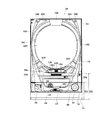
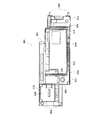
以下、パチンコ遊技機(以下、単に「パチンコ機」という)の実施の形態を、図面に基づいて詳細に説明する。図1はパチンコ機10の正面図であり、図2は、外枠11に対して内枠12と前面枠セット14とを開放した状態を示す斜視図である。但し、図2では便宜上、下皿ユニット13が内枠12から取り外された状態を示している。   Hereinafter, embodiments of a pachinko gaming machine (hereinafter simply referred to as “pachinko machines”) will be described in detail with reference to the drawings. FIG. 1 is a front view of the pachinko machine 10, and FIG. 2 is a perspective view showing a state in which the inner frame 12 and the front frame set 14 are opened with respect to the outer frame 11. However, FIG. 2 shows a state in which the lower plate unit 13 is removed from the inner frame 12 for convenience.

図1,2に示すように、パチンコ機10は、当該パチンコ機10の外殻を形成する外枠11と、この外枠11の一側部に開閉可能に支持された内枠12とを備えている。以下に、外枠11と内枠12との構成を個別に詳細に説明する。   As shown in FIGS. 1 and 2, the pachinko machine 10 includes an outer frame 11 that forms an outer shell of the pachinko machine 10, and an inner frame 12 that is supported on one side of the outer frame 11 so as to be opened and closed. ing. Below, the structure of the outer frame 11 and the inner frame 12 is demonstrated in detail separately.

外枠11は、木製の板材により全体として矩形状に構成され、小ネジ等の離脱可能な締結具により各板材が組み付けられている。本実施の形態では、外枠11の上下方向の外寸は809mm(内寸771mm)、左右方向の外寸は518mm(内寸480mm)となっている。なお、外枠11は樹脂やアルミニウム等の軽金属により構成されていてもよい。   The outer frame 11 is formed in a rectangular shape as a whole by a wooden plate material, and each plate material is assembled by a detachable fastener such as a small screw. In the present embodiment, the outer dimension of the outer frame 11 is 809 mm (inner dimension 771 mm), and the outer dimension in the left and right direction is 518 mm (inner dimension 480 mm). The outer frame 11 may be made of a light metal such as resin or aluminum.

内枠12の開閉軸線はパチンコ機10の正面からみてハンドル(後述する遊技球発射ハンドル18)設置箇所の反対側(図1のパチンコ機10の左側)で上下に延びるように設定されており、この開閉軸線を軸心にして内枠12が前方側に十分に開放できるようになっている。例えば、内枠12の開閉軸線がハンドル設置箇所側(図1のパチンコ機10の右側)で上下方向にあるとすると、内枠12を開放する際に遊技球発射ハンドル18の頭部等が隣なりのパチンコ機やカードユニット(球貸しユニット)に干渉することになり、内枠12を十分に開放できない。また、内枠12は合成樹脂、具体的にはABS(アクリロニトリル−ブタジエン−スチレン)樹脂により構成されている。こうすることで、粘性が高く衝撃に強くでき、低コストで製造できる。   The opening / closing axis of the inner frame 12 is set so as to extend vertically on the opposite side (left side of the pachinko machine 10 in FIG. 1) from the position where the handle (game ball launching handle 18 described later) is installed when viewed from the front of the pachinko machine 10. The inner frame 12 can be sufficiently opened forward with the opening / closing axis as an axis. For example, assuming that the opening / closing axis of the inner frame 12 is in the vertical direction on the handle installation location side (the right side of the pachinko machine 10 in FIG. 1), when the inner frame 12 is opened, the head of the game ball launch handle 18 is adjacent to the head. The inner frame 12 cannot be fully opened because it interferes with the pachinko machine or card unit (ball lending unit). The inner frame 12 is made of a synthetic resin, specifically, ABS (acrylonitrile-butadiene-styrene) resin. By doing so, it is highly viscous and resistant to impact, and can be manufactured at low cost.

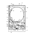
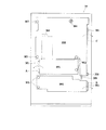
内枠12の構成を図3も用いて詳細に説明する。図3は、パチンコ機10から前面枠セット14を取り外した状態を示す正面図である(但し、図3では便宜上、遊技盤30面上の遊技領域内の構成を空白で示している)。   The configuration of the inner frame 12 will be described in detail with reference to FIG. FIG. 3 is a front view showing a state in which the front frame set 14 is removed from the pachinko machine 10 (however, in FIG. 3, the structure in the game area on the surface of the game board 30 is shown blank for convenience).

内枠12は、大別すると、その最下部に取り付けられた下皿ユニット13と、この下皿ユニット13よりも上側の範囲で内枠12の左側の上下方向の開閉軸線を軸心にして開閉自在に取り付けられた前面枠セット14と、後述する樹脂ベース20と、この樹脂ベース20の後側に取り付けられる遊技盤30とを備えている。これらの各構成を以下に詳細に説明する。   The inner frame 12 is roughly divided into a lower tray unit 13 attached to the lowermost portion thereof, and an opening / closing axis about the vertical opening / closing axis on the left side of the inner frame 12 in the range above the lower tray unit 13. A front frame set 14 that is freely attached, a resin base 20 that will be described later, and a game board 30 that is attached to the rear side of the resin base 20 are provided. Each of these configurations will be described in detail below.

下皿ユニット13は、内枠12に対してネジ等の締結具により固定されている。この下皿ユニット13の前面側には、下皿15と球抜きレバー17と遊技球発射ハンドル18と灰皿22と音出力口24が設けられている。球受皿としての下皿15は、下皿ユニット13のほぼ中央部に設けられており、排出口16より排出された遊技球が下皿15内に貯留可能になっている。球抜きレバー17は、下皿15内の遊技球を抜くためのものであり、この球抜きレバー17を図1で左側に移動させることにより、下皿15の底面の所定箇所が開口され、下皿15内に貯留された遊技球を下皿15の底面の開口部分を通して下方向外部に抜くことができる。遊技球発射ハンドル18は、下皿15よりも右方で手前側に突出して配設されている。遊技者による遊技球発射ハンドル18の操作に応じて、遊技球発射装置38によって遊技球が後述する遊技盤30の方へ打ち込まれるようになっている。遊技球発射装置38は、遊技球発射ハンドル18と後述する電磁式遊技球発射部228(図6参照)などで構成されている。なお、上述した遊技球発射装置38が本発明における遊技球発射手段に相当する。音出力口24は、下皿ユニット13内あるいは背面に設けられたスピーカからの音を出力するための出力口である。また、灰皿22は下皿15の左方に設けられている。灰皿22は左右方向(水平方向)の軸線を軸心にして回動(例えば前方側に向けて前回り)するように、その右側が下皿15に片持ち支持されている。   The lower plate unit 13 is fixed to the inner frame 12 with a fastener such as a screw. On the front side of the lower tray unit 13, a lower tray 15, a ball release lever 17, a game ball launch handle 18, an ashtray 22, and a sound output port 24 are provided. The lower tray 15 as a ball receiving tray is provided at the substantially central portion of the lower tray unit 13, and the game balls discharged from the discharge port 16 can be stored in the lower tray 15. The ball removal lever 17 is for removing a game ball in the lower plate 15. By moving the ball removal lever 17 to the left side in FIG. 1, a predetermined position on the bottom surface of the lower plate 15 is opened. The game balls stored in the dish 15 can be pulled out downward through the opening on the bottom surface of the lower dish 15. The game ball launching handle 18 is disposed so as to protrude to the front side on the right side of the lower plate 15. In accordance with the operation of the game ball launch handle 18 by the player, the game ball launcher 38 is driven into a game board 30 to be described later. The game ball launcher 38 includes a game ball launch handle 18 and an electromagnetic game ball launcher 228 (see FIG. 6), which will be described later. The game ball launching device 38 described above corresponds to the game ball launching means in the present invention. The sound output port 24 is an output port for outputting sound from a speaker provided in the lower plate unit 13 or on the back surface. The ashtray 22 is provided on the left side of the lower plate 15. The right side of the ashtray 22 is cantilevered by the lower plate 15 so that the ashtray 22 rotates around the axis in the left-right direction (horizontal direction) as an axis (for example, forwards toward the front side).

なお、下皿ユニット13はその大部分が内枠12と同様、ABS樹脂にて成形されている。こうすることで、粘性が高く衝撃に強くでき、低コストで製造できる。特に、下皿15を形成する表面層と下皿奥方の前面パネル部分とを難燃性のABS樹脂にて成形している。このため、この部分は燃え難くなっている。   Note that most of the lower dish unit 13 is molded of ABS resin in the same manner as the inner frame 12. By doing so, it is highly viscous and resistant to impact, and can be manufactured at low cost. In particular, the surface layer forming the lower plate 15 and the front panel portion at the back of the lower plate are formed of flame retardant ABS resin. For this reason, this part is difficult to burn.

また、前面枠セット14は、図2に示すように、内枠12に対して開閉可能に取り付けられており、内枠12と同様、パチンコ機10の正面からみて左側に上下に延びる開閉軸線を軸心にして前方側に開放できるようになっている。しかも前面枠セット14は内枠12の外側壁(リブ)12b(図3参照)内に嵌まり込むようにして取り付けられている。つまり、この前面枠セット14の側面の少なくとも一部が内枠12の外側壁(リブ)12b内に嵌まり込むようにして取り付けられているので、内枠12と前面枠セット14との隙間から異物(針状あるいは薄板状等のもの)を差し入れるなどの不正行為を防止できるようになっている。また、前面枠セット14は、内枠12と同様に、合成樹脂、具体的にはABS樹脂により構成されているので、粘性が高く衝撃に強くでき、低コストで製造できる。   As shown in FIG. 2, the front frame set 14 is attached to the inner frame 12 so as to be openable and closable. Like the inner frame 12, the front frame set 14 has an open / close axis extending vertically to the left when viewed from the front of the pachinko machine 10. It can be opened to the front side with an axial center. Moreover, the front frame set 14 is attached so as to fit into the outer wall (rib) 12b (see FIG. 3) of the inner frame 12. That is, since at least a part of the side surface of the front frame set 14 is attached so as to fit into the outer wall (rib) 12b of the inner frame 12, foreign matter (from the gap between the inner frame 12 and the front frame set 14) Such as a needle or thin plate) can be prevented. Further, since the front frame set 14 is made of a synthetic resin, specifically, an ABS resin, like the inner frame 12, the front frame set 14 is highly viscous and strong against impact, and can be manufactured at low cost.

一方、前面枠セット14の下部(上述の下皿15の上方位置)には、遊技球の受皿としての上皿19が一体的に設けられている。ここで、上皿19は、遊技球を一旦貯留し、一列に整列させながら遊技球発射装置38の方へ導出するための球受皿である。従来のパチンコ機では前面枠セットの下方に内枠に対し開閉可能な前飾り枠が設けられ、該前飾り枠に上皿が設けられていたのであるが、本実施の形態では前飾り枠が省略され、前面枠セット14に対し直接的に上皿19が設けられている。この上皿19も下皿15と同様、表面層が難燃性のABS樹脂にて成形される構成となっている。   On the other hand, an upper plate 19 as a receiving tray for game balls is integrally provided below the front frame set 14 (above the lower plate 15). Here, the upper plate 19 is a ball receiving tray for temporarily storing the game balls and guiding them to the game ball launching device 38 while aligning them in a line. In the conventional pachinko machine, a front decorative frame that can be opened and closed with respect to the inner frame is provided below the front frame set, and an upper plate is provided on the front decorative frame. The upper plate 19 is provided directly to the front frame set 14 and is omitted. Similar to the lower plate 15, the upper plate 19 has a structure in which the surface layer is formed of flame-retardant ABS resin.

ここで、前面枠セット14は、少なくとも遊技球発射ハンドル18に干渉しないようにして本パチンコ機10の下方に拡張して設けられており、具体的な数値を示すと、パチンコ機10の下端から前面枠セット14の下端までの寸法(図1のH1)は、既存の一機種で例えば約201mmであるのに対し、本パチンコ機10では30mm程小さく、約172mmとなっている。また、これに伴いパチンコ機10の下端から上皿19までの寸法(図1のH2)も小さくなっており、既存の一機種では例えば約298mmであるのに対し、本パチンコ機10では261mmとなっている。かかる構成では、上皿19の位置を下げたことにより、球貸し装置のノズル部と上皿19との距離が大きくなって貸し出される遊技球のこぼれ落ちなどが懸念されるが、本実施例では、当該ノズル部からの遊技球を受ける部分(向かって左側部分)で上皿19の周囲壁の一部を高くした(図1の高壁部19a)。これにより、上皿19の位置を下げた構成にあっても貸し遊技球のこぼれ落ち等の不都合が解消されるようになっている。なお、高壁部19aの高さ寸法は、上皿19の下げ寸法に見合うものであればよく、本実施例では25mmとした。   Here, the front frame set 14 is provided below the pachinko machine 10 so as not to interfere with at least the game ball launching handle 18. The dimension (H1 in FIG. 1) to the lower end of the front frame set 14 is, for example, about 201 mm in one existing model, but is about 172 mm, which is about 30 mm smaller in the pachinko machine 10. In addition, along with this, the dimension from the lower end of the pachinko machine 10 to the upper plate 19 (H2 in FIG. 1) is also reduced, and in the existing model, for example, it is about 298 mm, whereas in this pachinko machine 10, it is 261 mm. It has become. In such a configuration, there is a concern that the distance between the nozzle portion of the ball lending device and the upper plate 19 will increase due to the lowering of the position of the upper plate 19, and the spilled gaming balls will be rented. A part of the peripheral wall of the upper plate 19 was raised at a portion (left side portion) that receives the game ball from the nozzle portion (the high wall portion 19a in FIG. 1). Thereby, even if it has the structure which lowered the position of the top plate 19, inconveniences, such as spilling out of a rental game ball, are eliminated. In addition, the height dimension of the high wall part 19a should just be commensurate with the down dimension of the upper plate 19, and was 25 mm in the present Example.

図3に示すように、内枠12は、外形が矩形状の樹脂ベース20を主体に構成されており、樹脂ベース20の中央部には略円形状の窓孔21が形成されている。樹脂ベース20の後側には遊技盤30が着脱可能に装着されている。遊技盤30は四角形状の合板よりなり、その周縁部が樹脂ベース20(内枠12)の裏側に当接した状態で取着されている。従って、遊技盤30の前面部の略中央部分が樹脂ベース20の窓孔21を通じて内枠12の前面側に露出した状態となっている。なお、遊技盤30の上下方向の長さは476mm、左右方向の長さは452mmとなっている(従来と同等サイズ)。   As shown in FIG. 3, the inner frame 12 is mainly composed of a resin base 20 having a rectangular outer shape, and a substantially circular window hole 21 is formed at the center of the resin base 20. A game board 30 is detachably mounted on the rear side of the resin base 20. The game board 30 is made of a rectangular plywood and is attached in a state in which the peripheral edge thereof is in contact with the back side of the resin base 20 (inner frame 12). Accordingly, the substantially central portion of the front surface portion of the game board 30 is exposed to the front surface side of the inner frame 12 through the window hole 21 of the resin base 20. The game board 30 has a vertical length of 476 mm and a horizontal length of 452 mm (same size as before).

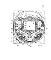
次に、図4を用いて遊技盤30の構成を説明する。図4は遊技盤30の構成を示す正面図である。遊技盤30は、一般入賞口31、可変入賞装置32、第1の始動口33(例えば作動チャッカ)、第2の始動口34(例えばスルーゲート)、可変表示装置ユニット35等を備えている。これらの一般入賞口31、可変入賞装置32、第1の始動口33(例えば作動チャッカ)、第2の始動口34(例えばスルーゲート)、可変表示装置ユニット35等は、遊技盤30における、ルータ加工によって形成された各貫通穴にそれぞれに配設され、遊技盤30前面側から木ネジ等により取り付けられている。前述の一般入賞口31、可変入賞装置32および第1の始動口33に遊技球が入球し、当該入球が後述する検出スイッチ(入賞口スイッチ221、カウントスイッチ223、作動口スイッチ224等)で検出され、この検出スイッチの出力に基づいて、上皿19(または下皿15)へ所定数の賞品球が払い出される。その他に、遊技盤30にはアウト口36が設けられており、各種入賞装置等に入球しなかった遊技球はこのアウト口36を通って図示しない球排出路の方へと案内されるようになっている。遊技盤30には、遊技球の落下方向を適宜分散、調整等するために多数の釘が植設されているとともに、風車37等の各種部材(役物)が配設されている。   Next, the configuration of the game board 30 will be described with reference to FIG. FIG. 4 is a front view showing the configuration of the game board 30. The game board 30 includes a general winning port 31, a variable winning device 32, a first starting port 33 (for example, an operation chucker), a second starting port 34 (for example, a through gate), a variable display unit 35, and the like. These general winning port 31, variable winning device 32, first starting port 33 (for example, operation chucker), second starting port 34 (for example, through gate), variable display unit 35, etc. It is arranged in each through hole formed by machining, and is attached from the front side of the game board 30 with wood screws or the like. A game ball enters the above-described general winning port 31, variable winning device 32, and first starting port 33, and the detected balls are described later (a winning port switch 221, a count switch 223, an operating port switch 224, etc.). Based on the output of the detection switch, a predetermined number of prize balls are paid out to the upper plate 19 (or the lower plate 15). In addition, the game board 30 is provided with an out port 36, so that game balls that have not entered the various winning devices etc. are guided through the out port 36 toward a ball discharge path (not shown). It has become. A number of nails are planted in the game board 30 in order to appropriately disperse and adjust the falling direction of the game balls, and various members (acts) such as the windmill 37 are arranged.

可変表示装置ユニット35は、第1の始動口33への入賞をトリガとして、識別情報としての第1図柄(例えば特別図柄)を表示画面43の第1図柄表示部43aに変動表示するとともに、第2の始動口34の通過をトリガとして、第2図柄(例えば普通図柄)を表示画面43の第2図柄表示部43bに変動表示する表示装置42を備えている。   The variable display device unit 35 variably displays a first symbol (for example, a special symbol) as identification information on the first symbol display unit 43a of the display screen 43 by using a winning at the first start port 33 as a trigger. A display device 42 that variably displays a second symbol (for example, a normal symbol) on the second symbol display unit 43 b of the display screen 43 using the passage of the two start ports 34 as a trigger is provided.

表示装置42は液晶表示装置として構成されており、後述する表示制御装置45により表示内容(第1図柄や第2図柄などを含む種々の表示内容)が制御される。この表示装置42の表示画面43の第2図柄表示部43bには、図4に示すように例えば「○」と「×」とで表した第2図柄が変動表示される。また、センターフレーム47は、第2図柄の変動表示の保留を示す複数個(この実施例では4個)保留ランプ44を備えている。遊技球が第2の始動口34を通過する毎に例えば表示装置42の第2図柄表示部43bの第2図柄(普通図柄)が変動し、その変動表示が所定図柄で停止した場合に第1の始動口33が所定時間だけ作動状態となる(開放される)よう構成されている。遊技球が第2の始動口34を通過した回数は最大4回まで保留され、その保留回数が保留ランプ44にて点灯表示されるようになっている。保留ランプ44は、複数のランプの点灯を切り換えることにより変動表示される構成の他、表示装置42の一部で変動表示される構成等であっても良い。なお、上述した表示装置42の第2図柄表示部43bが本発明における普通識別情報変動表示手段に相当する。   The display device 42 is configured as a liquid crystal display device, and display contents (various display contents including the first symbol and the second symbol) are controlled by a display control device 45 described later. In the second symbol display section 43b of the display screen 43 of the display device 42, as shown in FIG. 4, for example, the second symbols represented by “◯” and “x” are variably displayed. Further, the center frame 47 includes a plurality of (four in this embodiment) hold lamps 44 indicating the hold of the variation display of the second symbol. Each time the game ball passes through the second start opening 34, for example, the second symbol (ordinary symbol) of the second symbol display unit 43b of the display device 42 fluctuates, and the first symbol is displayed when the variation display stops at a predetermined symbol. The starting port 33 is configured to be activated (opened) for a predetermined time. The number of times that the game ball has passed through the second start opening 34 is held up to a maximum of 4 times, and the number of times the game ball is held is lit and displayed by the hold lamp 44. The hold lamp 44 may be configured to be variably displayed on a part of the display device 42 in addition to a configuration that is variably displayed by switching lighting of a plurality of lamps. In addition, the 2nd symbol display part 43b of the display apparatus 42 mentioned above corresponds to the normal identification information fluctuation | variation display means in this invention.

また、表示装置42の表示画面43の第1図柄表示部43aには、例えば左、中及び右の3つの図柄列が表示される。各図柄列は複数の図柄によって構成されており、これら図柄が図柄列毎にスクロールされるようにして表示装置42に可変表示されるようになっている。なお本実施の形態では、表示装置42(液晶表示装置)は8インチサイズの大型の液晶ディスプレイを備える。可変表示装置ユニット35には、表示装置42を囲むようにしてセンターフレーム47が配設されている。なお、上述した表示装置42が本発明における変動表示手段に相当し、上述した表示装置42の第1図柄表示部43aが本発明における識別情報変動表示手段に相当し、上述した表示制御装置45が本発明における表示制御手段に相当する。   In addition, in the first symbol display portion 43a of the display screen 43 of the display device 42, for example, three symbol rows of left, middle, and right are displayed. Each symbol row is composed of a plurality of symbols, and these symbols are variably displayed on the display device 42 so as to be scrolled for each symbol row. In the present embodiment, the display device 42 (liquid crystal display device) includes a large liquid crystal display having an 8-inch size. A center frame 47 is disposed in the variable display device unit 35 so as to surround the display device 42. The display device 42 described above corresponds to the fluctuation display means in the present invention, the first symbol display portion 43a of the display device 42 described above corresponds to the identification information fluctuation display means in the present invention, and the display control device 45 described above is provided. This corresponds to the display control means in the present invention.

可変入賞装置32は、通常は遊技球が入賞できない又は入賞し難い閉状態になっており、大当たりの際に遊技球が入賞しやすい開状態と通常の閉状態とに繰り返し作動されるようになっている。より詳しくは、第1の始動口33に対し遊技球が入賞すると表示装置42で第1図柄が変動表示され、その停止後の確定図柄が予め設定した特定の図柄の組合せとなったことを必要条件に特別遊技状態が発生する。そして、可変入賞装置32の大入賞口が所定の開放状態となり、遊技球が入賞しやすい状態(大当たり状態)になるよう構成されている。具体的には、所定時間の経過又は所定個数の入賞を1ラウンドとして、可変入賞装置32の大入賞口が所定回数繰り返し開放される。遊技球が第1の始動口33を通過した回数は最大4回まで保留され、その保留回数が保留ランプ46にて点灯表示されるようになっている。なお、保留ランプ46は、表示装置42の一部で変動表示される構成等であっても良い。   The variable winning device 32 is normally in a closed state in which a game ball cannot be won or difficult to win, and is repeatedly operated between an open state in which a game ball is easy to win and a normal closed state in a big win. ing. More specifically, when a game ball wins the first start port 33, the display device 42 displays the first symbol in a variable manner, and the final symbol after the stop needs to be a combination of specific symbols set in advance. A special gaming state occurs in the condition. The large winning opening of the variable winning device 32 is in a predetermined open state, and the game ball is configured to be in a state where it is easy to win a prize (a big hit state). Specifically, the passage of a predetermined time or a predetermined number of winnings is defined as one round, and the big winning opening of the variable winning device 32 is repeatedly opened a predetermined number of times. The number of times that the game ball has passed through the first start port 33 is held up to a maximum of 4 times, and the number of times that the game ball is held is lit and displayed by the hold lamp 46. Note that the hold lamp 46 may be configured to be variably displayed on a part of the display device 42.

なお、第1図柄は、特別遊技状態という遊技者にとっての利益を付与するためのものであり、第2図柄は、第1図柄よりも小さな利益(第1の始動口33の開放という利益)を付与するためのものである。   In addition, the 1st symbol is for granting a profit for the player in a special gaming state, and the 2nd symbol is a profit smaller than the 1st symbol (a benefit of opening the first start port 33). It is for granting.

また、遊技盤30には、遊技球発射装置38から発射された遊技球を遊技盤30上部へ案内するためのレールユニット50が取り付けられており、遊技球発射ハンドル18の回動操作に伴い発射された遊技球はレールユニット50を通じて所定の遊技領域に案内されるようになっている。レールユニット50はリング状をなす樹脂成型品(例えば、フッ素樹脂が添加されて成形されたもの)にて構成されており、内外二重に一体形成された内レール51と外レール52とを有する。なお、レールユニット50はフッ素樹脂を添加して成形されているので、図3に示す奥面50aについての遊技球の摩擦抵抗を少なくできる。内レール51は上方の約1/4ほどを除いて略円環状に形成され、一部(主に左側部)が内レール51に向かい合うようにして外レール52が形成されている。かかる場合、内レール51と外レール52とにより誘導レールが構成され、これら各レール51,52が所定間隔を隔てて並行する部分(向かって左側の部分)により球案内通路が形成されている。なお、球案内通路は、遊技盤30との当接面を有した溝状、すなわち手前側を開放した溝状に形成されている。   The game board 30 is also provided with a rail unit 50 for guiding the game ball launched from the game ball launching device 38 to the upper part of the game board 30, and is released in accordance with the turning operation of the game ball launch handle 18. The played game balls are guided to a predetermined game area through the rail unit 50. The rail unit 50 is formed of a ring-shaped resin molded product (for example, a product molded by adding a fluororesin), and has an inner rail 51 and an outer rail 52 integrally formed in an inner and outer double. . In addition, since the rail unit 50 is shape | molded by adding a fluororesin, it can reduce the frictional resistance of the game ball about the back surface 50a shown in FIG. The inner rail 51 is formed in a substantially annular shape except for about ¼ of the upper part, and the outer rail 52 is formed so that a part (mainly the left side) faces the inner rail 51. In such a case, a guide rail is constituted by the inner rail 51 and the outer rail 52, and a spherical guide passage is formed by a portion (the left portion facing) where the rails 51 and 52 are parallel to each other at a predetermined interval. The ball guide passage is formed in a groove shape having a contact surface with the game board 30, that is, a groove shape in which the front side is opened.

内レール51の先端部分(図4の左上部)には戻り球防止部材53が取着されている。これにより、一旦、内レール51及び外レール52間の球案内通路から遊技盤30の上部へと案内された遊技球が再度球案内通路内に戻ってしまうといった事態が防止されるようになっている。また、外レール52には、遊技球の最大飛翔部分に対応する位置(図4の右上部:外レール52の先端部に相当する部位)に返しゴム54が取着されている。従って、所定以上の勢いで発射された遊技球は、返しゴム54に当たって跳ね返されるようになっている。外レール52の内側面には、遊技球の飛翔をより滑らかなものとするべく、つまり遊技球の摩擦抵抗を少なくするべく、長尺状をなすステンレス製の金属帯としての摺動プレート55が取着されている。   A return ball preventing member 53 is attached to the tip portion of the inner rail 51 (the upper left portion in FIG. 4). This prevents a situation in which the game ball once guided from the ball guide path between the inner rail 51 and the outer rail 52 to the upper part of the game board 30 returns to the ball guide path again. Yes. Further, a return rubber 54 is attached to the outer rail 52 at a position corresponding to the maximum flight portion of the game ball (upper right portion in FIG. 4: a portion corresponding to the tip portion of the outer rail 52). Accordingly, the game ball fired at a predetermined momentum or more hits the return rubber 54 and is bounced back. On the inner surface of the outer rail 52, there is a sliding plate 55 as a long metal strip made of stainless steel in order to make the flight of the game ball smoother, that is, to reduce the frictional resistance of the game ball. It is attached.

また、レールユニット50の外周部には、外方へ張り出した円弧状のフランジ56が形成されている。フランジ56は、遊技盤30に対する取付面を構成する。レールユニット50が遊技盤30に取り付けられる際には、遊技盤30上にフランジ56が当接され、その状態で、当該フランジ56に形成された複数の透孔にネジ等が挿通されて遊技盤30に対するレールユニット50の締結がなされるようになっている。この実施例では、レールユニット50の少なくとも左側を遊技盤30に強固に締結するために、レールユニット50の左側はその右側よりも多いネジで遊技盤30に締結されているので、レールユニット50の左側についての遊技盤30への密着性を上げることができ、遊技球の球飛びを良くすることができる。レールユニット50の左側が遊技盤30に対してぐらついているとこのレールユニット50に出射された遊技球の勢いが当該ぐらつきにより吸収されてしまうからである。   An arc-shaped flange 56 projecting outward is formed on the outer peripheral portion of the rail unit 50. The flange 56 constitutes a mounting surface for the game board 30. When the rail unit 50 is attached to the game board 30, the flange 56 is brought into contact with the game board 30, and in this state, screws or the like are inserted into the plurality of through holes formed in the flange 56 and the game board 30. The rail unit 50 is fastened to 30. In this embodiment, in order to firmly fasten at least the left side of the rail unit 50 to the game board 30, the left side of the rail unit 50 is fastened to the game board 30 with more screws than the right side. Adhesiveness to the game board 30 on the left side can be improved, and a game ball can be improved. This is because if the left side of the rail unit 50 is wobbled with respect to the game board 30, the momentum of the game ball emitted to the rail unit 50 is absorbed by the wobble.

さらに本実施の形態では、正面から見てレールユニット50の上下左右の各端部は略直線状に(平坦に)形成されている。つまり、レールユニット50の上下左右の各端部においてはフランジ56が切り落とされ、パチンコ機10における有限の領域にてレール径の拡張、すなわち遊技盤30上の遊技領域の拡張が図られるようになっている。   Furthermore, in the present embodiment, the top, bottom, left, and right ends of the rail unit 50 are formed in a substantially straight line (flat) when viewed from the front. That is, the flange 56 is cut off at each of the upper, lower, left and right ends of the rail unit 50, and the rail diameter can be expanded in a limited area in the pachinko machine 10, that is, the game area on the game board 30 can be expanded. ing.

内レール51及び外レール52間の球案内通路の入口には、同球案内通路の一部を閉鎖するようにして凸部57が形成されている。この凸部57は、内レール51からレールユニット50下端部にかけて略鉛直方向に設けられ、遊技領域まで至らず球案内通路内を逆流してくるファール球をファール球通路63(図3参照)に導くための役目をなす。なお、遊技盤30の右下隅部及び左下隅部は、証紙(例えば製造番号が記載されている)等のシール(図4のS1,S2)やプレートを貼着するためのスペースとなっており、この貼着スペースを確保するために、フランジ56に切欠58,59が形成されている。遊技盤30の右下隅部や左下隅部に、証紙等のシール(図4のS1,S2)を貼着することで、遊技盤30と証紙との一義性を持たせることができる。   A convex portion 57 is formed at the entrance of the ball guide passage between the inner rail 51 and the outer rail 52 so as to close a part of the ball guide passage. The convex portion 57 is provided in a substantially vertical direction from the inner rail 51 to the lower end portion of the rail unit 50, and a foul ball that does not reach the game area and flows backward in the ball guide passage is used as a foul ball passage 63 (see FIG. 3). Play a role in guiding. Note that the lower right corner and the lower left corner of the game board 30 are spaces for attaching stickers (for example, S1 and S2 in FIG. 4) and plates such as stamps (for example, serial numbers are described). In order to secure this adhering space, notches 58 and 59 are formed in the flange 56. By sticking a sticker such as a certificate (S1, S2 in FIG. 4) to the lower right corner or the lower left corner of the game board 30, the game board 30 and the certificate can be uniquely defined.

次に、遊技領域について説明する。遊技領域は、レールユニット50の内周部(内外レール)により略円形状に区画形成されており、特に本実施の形態では、遊技盤30の盤面上に区画される遊技領域が従来よりもはるかに大きく構成されている。本実施の形態では、外レール52の最上部地点から遊技盤30下部までの間の距離は445mm(従来品よりも58mm長い)、外レール52の極左位置から内レール51の極右位置までの間の距離は435mm(従来品よりも50mm長い)となっている。また、内レール51の極左位置から内レール51の極右位置までの間の距離は418mmとなっている。   Next, the game area will be described. The game area is partitioned and formed in a substantially circular shape by the inner peripheral part (inner and outer rails) of the rail unit 50. In particular, in the present embodiment, the game area partitioned on the board surface of the game board 30 is much more than conventional. It is composed largely. In the present embodiment, the distance between the uppermost point of the outer rail 52 and the lower part of the game board 30 is 445 mm (58 mm longer than the conventional product), and is from the extreme left position of the outer rail 52 to the extreme right position of the inner rail 51. The distance is 435 mm (50 mm longer than the conventional product). The distance from the extreme left position of the inner rail 51 to the extreme right position of the inner rail 51 is 418 mm.

本実施の形態では、遊技領域を、パチンコ機10の正面から見て、内レール51及び外レール52によって囲まれる領域のうち、内外レール51,52の並行部分である誘導レールの領域を除いた領域としている。従って、遊技領域と言った場合には誘導レール部分は含まないため、遊技領域の向かって左側限界位置は外レール52によってではなく内レール51によって特定される。同様に、遊技領域の向かって右側限界位置は内レール51によって特定される。また、遊技領域の下側限界位置は遊技盤30の下端位置によって特定される。また、遊技領域の上側限界位置は外レール52によって特定される。   In the present embodiment, the game area is a region surrounded by the inner rail 51 and the outer rail 52 as viewed from the front of the pachinko machine 10, except for a guide rail region that is a parallel part of the inner and outer rails 51 and 52. As an area. Accordingly, since the game area does not include the guide rail portion, the left limit position toward the game area is specified not by the outer rail 52 but by the inner rail 51. Similarly, the right limit position toward the game area is specified by the inner rail 51. The lower limit position of the game area is specified by the lower end position of the game board 30. The upper limit position of the game area is specified by the outer rail 52.

従って、本実施の形態では、遊技領域の幅(左右方向の最大幅)は、418mmであり、遊技領域の高さ(上下方向の最大幅)は、445mmである。   Therefore, in the present embodiment, the width of the game area (maximum width in the left-right direction) is 418 mm, and the height of the game area (maximum width in the vertical direction) is 445 mm.

ここで、前記遊技領域の幅は、少なくとも380mm以上あることが望ましい。より好ましくは390mm以上、400mm以上、410mm以上、420mm以上、430mm以上、440mm以上、450mm以上、さらに460mm以上であることが望ましい。もちろん、470mm以上であってもよい。すなわち、遊技領域の幅は、遊技領域拡大という観点からは大きい程好ましい。また、遊技領域の高さは、少なくとも400mm以上あることが望ましい。より好ましくは410mm以上、420mm以上、430mm以上、440mm以上、450mm以上、さらには460mm以上であることがより望ましい。もちろん、470mm以上、480mm以上、490mm以上としてもよい。すなわち、遊技領域の高さは、遊技領域拡大という観点からは大きい程好ましい。なお、上記幅及び高さの組合せについては、上記数値を任意に組み合わせたものとしてもよい。   Here, the width of the gaming area is preferably at least 380 mm. More preferably, it is 390 mm or more, 400 mm or more, 410 mm or more, 420 mm or more, 430 mm or more, 440 mm or more, 450 mm or more, and further 460 mm or more. Of course, it may be 470 mm or more. That is, the width of the game area is preferably as large as possible from the viewpoint of expanding the game area. The height of the game area is preferably at least 400 mm. More preferably, it is 410 mm or more, 420 mm or more, 430 mm or more, 440 mm or more, 450 mm or more, and further 460 mm or more. Of course, it is good also as 470 mm or more, 480 mm or more, and 490 mm or more. In other words, the height of the game area is preferably as large as possible from the viewpoint of expanding the game area. In addition, about the combination of the said width | variety and height, it is good also as what combined the said numerical value arbitrarily.

本実施の形態では、遊技盤30面に対する遊技領域の面積の比率は約70%と、従来に比べ格段に面積比が大きいものとなっている。なお、遊技盤30面に対する遊技領域の面積比は、従来では50%程度に過ぎなかったことから、遊技盤30を共通とした前提においてはかなり遊技領域を拡大しているといえる。尚、パチンコ機10の外形は遊技場への設置の都合上製造者間でほぼ統一されており、遊技盤30の大きさも同様とせざるを得ない状況下において、上記のように遊技盤30面に対する遊技領域の面積の比率を約20%も高めたことは、遊技領域拡大の観点で非常に有意義である。ここで、前記比率は、少なくとも60%以上であることが望ましい。さらに好ましくは65%以上であり、より好ましくは70%以上である。また、本実施形態の場合を越えて75%以上であれば、一層望ましい。さらには、80%以上であってもよい。   In the present embodiment, the ratio of the area of the game area to the surface of the game board 30 is about 70%, which is a much larger area ratio than before. Note that the area ratio of the game area to the surface of the game board 30 is only about 50% in the past, so it can be said that the game area is considerably expanded on the premise that the game board 30 is shared. It should be noted that the external shape of the pachinko machine 10 is almost uniform among manufacturers for the convenience of installation in the game hall, and in the situation where the size of the game board 30 must be the same, the surface of the game board 30 as described above. Increasing the ratio of the area of the gaming area to about 20% is very significant from the viewpoint of expanding the gaming area. Here, the ratio is preferably at least 60% or more. More preferably, it is 65% or more, More preferably, it is 70% or more. Further, if it is 75% or more exceeding the case of this embodiment, it is more desirable. Furthermore, it may be 80% or more.

また、パチンコ機10全体の正面側の面積に対する遊技領域の面積の比率は約40%と、従来に比べ格段に面積比が大きいものとなっている。なお、パチンコ機10全体の正面側の面積に対する遊技領域の面積比は、35パーセント以上であるのが望ましい。もちろん、40パーセント以上としてもよいし、45パーセント以上、又は50パーセント以上としてもよい。   Further, the ratio of the area of the game area to the area of the front side of the entire pachinko machine 10 is about 40%, which is a much larger area ratio than in the past. The area ratio of the game area to the area on the front side of the entire pachinko machine 10 is desirably 35% or more. Of course, it may be 40% or more, 45% or more, or 50% or more.

なお、可変表示装置ユニット35の両側に位置する第2の始動口34は、該第2の始動口34を通過した遊技球が中央の方へ寄せられるような案内機構を有している。これにより、遊技領域が左右方向に拡張されている場合であっても、遊技球を中央の第1の始動口33や可変入賞装置32の方へと案内することができ、ひいては、遊技領域が拡張されることにより遊技球が入賞しにくくなることによる興趣の低下が抑制されるようになっている。さらには、遊技領域が左右方向に拡張されていることによって、風車37、第2の始動口34、複数の釘(遊技球を中央に誘導するための誘導釘)、他の役物を種々配設することができ、可変表示装置ユニット35の左右両側の遊技領域での遊技球の挙動を一層面白くすることができるようになっている。また、遊技領域が上下方向にも拡張されていることから、さらに風車37、第2の始動口34、複数の釘、他の役物を種々配設することができ、遊技領域での上下方向の遊技球の挙動をより一層面白くすることができるようになっている。   In addition, the 2nd starting port 34 located in the both sides of the variable display apparatus unit 35 has a guide mechanism in which the game ball which passed this 2nd starting port 34 is approached toward the center. Thereby, even when the game area is expanded in the left-right direction, the game ball can be guided toward the center first starting port 33 and the variable prize-winning device 32. By expanding, it is possible to suppress a decrease in interest due to difficulty in winning game balls. Furthermore, by extending the game area in the left-right direction, various arrangements of the windmill 37, the second start port 34, a plurality of nails (guide nails for guiding the game ball to the center), and other accessories are arranged. Thus, the behavior of the game ball in the game areas on the left and right sides of the variable display device unit 35 can be made more interesting. In addition, since the game area is also expanded in the vertical direction, various windmills 37, second start ports 34, a plurality of nails, and other accessories can be further arranged in the vertical direction in the game area. The behavior of the game ball can be made even more interesting.

図3の説明に戻り、前記樹脂ベース20において、窓孔21(遊技盤30)の下方には、遊技球発射装置38より発射された直後に遊技球を案内するための発射レール61が取り付けられている。発射レール61は、その後方の金属板62を介して樹脂ベース20に取付固定されており、所定の発射角度(射出角度)にて直線的に延びるよう構成されている。従って、遊技球発射ハンドル18の回動操作に伴い発射された遊技球は、まずは発射レール61に沿って斜め上方に打ち出され、その後前述した通りレールユニット50の球案内通路を通じて所定の遊技領域に案内されるようになっている。   Returning to the description of FIG. 3, in the resin base 20, below the window hole 21 (game board 30), a launch rail 61 for guiding the game ball immediately after being launched from the game ball launcher 38 is attached. ing. The firing rail 61 is fixedly attached to the resin base 20 via a metal plate 62 behind the firing rail 61, and is configured to extend linearly at a predetermined firing angle (injection angle). Accordingly, a game ball that is launched in accordance with the turning operation of the game ball launching handle 18 is first launched obliquely upward along the launch rail 61, and thereafter, into the predetermined game area through the ball guide passage of the rail unit 50 as described above. Guided.

本パチンコ機10の場合、遊技領域が従来よりも大幅に拡張されることは既に述べたが、かかる構成下では、誘導レールの曲率を小さくせざるを得ないことから、打出球を安定化させるための工夫を要する。そこで本実施の形態では、遊技球の発射位置を低くするとともに発射レール61の傾斜角度(発射角度)を既存のものよりも幾分大きくし(すなわち発射レール61を立ち上げるようにし)、さらに発射レール61の長さを既存のものよりも長くして十分な長さの球誘導距離を確保するようにしている。これにより、遊技球発射装置38から発射された遊技球をより安定した状態で誘導レールに案内できるようにしている。この場合特に、発射レール61を、遊技球発射装置38の発射位置から遊技領域の中央位置(アウト口36)を越える位置まで延びるよう形成している。   In the case of this pachinko machine 10, it has already been described that the game area is greatly expanded as compared with the prior art, but under such a configuration, the curvature of the guide rail must be reduced, so that the launch ball is stabilized. Need some ingenuity. Therefore, in the present embodiment, the launch position of the game ball is lowered, and the inclination angle (launch angle) of the launch rail 61 is made somewhat larger than the existing one (that is, the launch rail 61 is raised) to further launch. The length of the rail 61 is made longer than that of the existing one so as to ensure a sufficiently long ball guiding distance. Thereby, the game ball launched from the game ball launcher 38 can be guided to the guide rail in a more stable state. In this case, in particular, the launch rail 61 is formed to extend from the launch position of the game ball launcher 38 to a position beyond the center position (out port 36) of the game area.

また、発射レール61とレールユニット50(誘導レール)との間には所定間隔の隙間があり、この隙間より下方にファール球通路63が形成されている。従って、仮に、遊技球発射装置38から発射された遊技球が戻り球防止部材53まで至らずファール球として誘導レール内を逆戻りする場合には、そのファール球がファール球通路63を介して下皿15に排出される。因みに、本実施の形態の場合、発射レール61の長さは約240mm、発射レール先端部の隙間の長さ(発射レール61の延長線上の長さ)は約40mmである。   In addition, there is a predetermined gap between the firing rail 61 and the rail unit 50 (guide rail), and a foul ball passage 63 is formed below the gap. Therefore, if the game ball launched from the game ball launching device 38 does not reach the return ball prevention member 53 and returns to the inside of the guide rail as a foul ball, the foul ball passes through the foul ball passage 63 to the lower plate. 15 is discharged. Incidentally, in the case of the present embodiment, the length of the firing rail 61 is about 240 mm, and the length of the gap at the tip of the firing rail (the length on the extension line of the firing rail 61) is about 40 mm.

ファール球が誘導レール内を逆流してくる際、その多くは外レール52に沿って流れ、外レール52の下端部に到達した時点で下方に落下するが、一部のファール球は誘導レール内で暴れ、内レール51側へ跳ね上がるものもある。この際、跳ね上がったファール球は、球案内通路入口の前記凸部57に当たり、ファール球通路63に誘導される。これにより、ファール球の全てがファール球通路63に確実に案内されるようになる。これにより、ファール球と次に発射される遊技球との干渉が抑制される。   When the foul spheres flow backward in the guide rail, most of them flow along the outer rail 52 and fall downward when reaching the lower end of the outer rail 52. There is also a thing that jumps to the inner rail 51 side. At this time, the splashed foul ball hits the convex portion 57 at the entrance of the ball guide passage and is guided to the foul ball passage 63. Thereby, all of the foul balls are surely guided to the foul ball passage 63. This suppresses interference between the foul ball and the next game ball to be launched.

なお、詳しい図面の開示は省略するが、遊技球発射装置38には、前面枠セット14側の球出口(上皿19の最下流部より通じる球出口)から遊技球が1つずつ供給される。この際、本実施の形態では遊技球の発射位置を低くしたため、前面枠セット14側の球出口から前記発射位置への落差が大きくなるが、発射レール61の基端部付近にはその右側と手前側にそれぞれガイド部材65,66を設置した。これにより、前面枠セット14側の球出口から供給される遊技球が常に所定の発射位置にセットされ、安定した発射動作が実現できる。また、遊技球発射装置38には、後述する電磁式遊技球発射部228が設けられ、遊技球発射ハンドル18の操作量に応じた強さで遊技球が発射されるようになっている。   Although detailed disclosure of the drawings is omitted, game balls are supplied to the game ball launcher 38 one by one from the ball outlet on the front frame set 14 side (the ball outlet leading from the most downstream portion of the upper plate 19). . At this time, since the launch position of the game ball is lowered in the present embodiment, the drop from the exit of the ball on the front frame set 14 side to the launch position becomes large. Guide members 65 and 66 were installed on the front side. Thereby, the game ball supplied from the ball exit on the front frame set 14 side is always set at a predetermined launch position, and a stable launch operation can be realized. In addition, the game ball launching device 38 is provided with an electromagnetic game ball launching unit 228 to be described later so that the game ball is launched with a strength corresponding to the amount of operation of the game ball launching handle 18.

なお、図3中の符号67は上皿19に通ずる排出口であり、この排出口67を介して遊技球が上皿19に排出される。排出口67には、略水平方向の回転軸を軸心として略水平状態と略垂直状態とに変位する開閉式のシャッタ68が取り付けられている。前面枠セット14を内枠12から開放した状態(図3の状態)では、バネ等の付勢力によりシャッタ68が略水平状態から略垂直状態となり、排出口67から遊技球がこぼれ落ちないようにこの排出口67を閉鎖する。また、前面枠セット14を閉鎖した状態では、当該前面枠セット14の裏面に設けられた球通路樋69(図2参照)によりシャッタ68が押し開けられて略水平状態になり、排出口67の方へ排出された遊技球はもれなく球通路樋69を通って上皿19に排出されるようになる。従って、前飾り枠が省略され前面枠セット14に対して上皿19が直接設けられる構成とした本パチンコ機10において、前面枠セット14の開放に際し払出通路内等の遊技球がパチンコ機10外にこぼれ落ちてしまうといった不都合が防止できるようになっている。   In addition, the code | symbol 67 in FIG. 3 is the discharge port connected to the upper plate 19, and a game ball is discharged to the upper plate 19 through this discharge port 67. FIG. The discharge port 67 is provided with an openable / closable shutter 68 that is displaced between a substantially horizontal state and a substantially vertical state with a substantially horizontal rotation axis as an axis. When the front frame set 14 is released from the inner frame 12 (the state shown in FIG. 3), the shutter 68 is changed from a substantially horizontal state to a substantially vertical state by an urging force of a spring or the like. The discharge port 67 is closed. When the front frame set 14 is closed, the shutter 68 is pushed open by a ball passage rod 69 (see FIG. 2) provided on the back surface of the front frame set 14 to be in a substantially horizontal state. The game ball discharged toward the direction passes through the ball passage ridge 69 and is discharged to the upper plate 19 without any leakage. Therefore, in the pachinko machine 10 in which the front decorative frame is omitted and the upper plate 19 is directly provided to the front frame set 14, the game balls in the payout passage and the like are outside the pachinko machine 10 when the front frame set 14 is opened. Inconveniences such as spilling out can be prevented.

樹脂ベース20には、窓孔21の右下部に略四角形状の小窓71が設けられている。従って、遊技盤30の右下隅部に張られた証紙などのシール(図4のS1)は、この小窓71を通じて視認できるようになっている。また、この小窓71からシール等を貼り付けることも可能となっている。   The resin base 20 is provided with a substantially rectangular small window 71 at the lower right portion of the window hole 21. Therefore, a sticker such as a stamp (S1 in FIG. 4) stretched at the lower right corner of the game board 30 can be seen through the small window 71. Further, a sticker or the like can be pasted from the small window 71.

また、図3に示すように、内枠12の左端部には、前面枠セット14の支持機構として、支持金具81,82が取り付けられている。上側の支持金具81には図の手前側に切欠を有する支持孔83が設けられ、下側の支持金具82には鉛直方向に突出した突起軸84が設けられている。   As shown in FIG. 3, support brackets 81 and 82 are attached to the left end portion of the inner frame 12 as a support mechanism for the front frame set 14. The upper support fitting 81 is provided with a support hole 83 having a notch on the front side of the figure, and the lower support fitting 82 is provided with a protruding shaft 84 protruding in the vertical direction.

図3に示すように、内枠12の上側には、前面枠セット14が内枠12に対して開かれたことを検出する前面枠セット開検出スイッチ90が設けられている。前面枠セット14が開かれると、前面枠セット開検出スイッチ90からホール内(パチンコ店内)用コンピュータへ出力されるようになっている。また、前面枠セット14が閉じられると、図5に示す前面枠セット14の金属製の補強板132,131が図3に示す内枠12の一対の金具92に接触するようになっており、前面枠セット14のアースが確保されている。   As shown in FIG. 3, a front frame set open detection switch 90 that detects that the front frame set 14 is opened with respect to the inner frame 12 is provided above the inner frame 12. When the front frame set 14 is opened, it is output from the front frame set open detection switch 90 to the computer for the hall (in the pachinko parlor). When the front frame set 14 is closed, the metal reinforcing plates 132 and 131 of the front frame set 14 shown in FIG. 5 come into contact with the pair of metal fittings 92 of the inner frame 12 shown in FIG. The grounding of the front frame set 14 is secured.

ここで、前述した前面枠セット14について、図1,図5を参照しつつより詳細に説明する。図5は、前面枠セット14の背面図である。前面枠セット14には前記遊技領域のほとんどを外部から視認することができるよう略楕円形状の窓部101が形成されている。詳しくは、窓部101は、その左右側の略中央部が、上下側に比べて比較的緩やかに湾曲した形状となっている。なお、前記略中央部が直線状になるようにしてもよい。本実施の形態において、窓部101の上端(外レール52の最上部、遊技領域の上端)と、前面枠セット14の上端との間の距離(いわゆる上部フレーム部分の上下幅)は61mmとなっており、85mm〜95mm程度上部フレーム幅がある従来技術に比べて著しく短くなっている。これにより、遊技領域の上部領域が確保されやすくなるとともに、大型の可変表示装置ユニット35も比較的上方に配置することができるようになっている。前面枠セット14の上端との間の距離は80mm以下であることが望ましく、より望ましくは70mm以下であり、さらに望ましくは60mm以下である。もちろん、所定の強度が確保できるのであれば、50mm以下であっても差し支えない。   Here, the front frame set 14 described above will be described in more detail with reference to FIGS. FIG. 5 is a rear view of the front frame set 14. The front frame set 14 is formed with a substantially elliptical window 101 so that most of the game area can be viewed from the outside. Specifically, the window portion 101 has a shape in which a substantially central portion on the left and right sides is curved relatively gently as compared with the upper and lower sides. The substantially central portion may be linear. In the present embodiment, the distance between the upper end of the window portion 101 (the uppermost portion of the outer rail 52 and the upper end of the game area) and the upper end of the front frame set 14 (the vertical width of the so-called upper frame portion) is 61 mm. It is significantly shorter than the prior art having an upper frame width of about 85 mm to 95 mm. As a result, the upper area of the game area can be easily secured, and the large-sized variable display device unit 35 can be arranged relatively upward. The distance between the upper end of the front frame set 14 is desirably 80 mm or less, more desirably 70 mm or less, and further desirably 60 mm or less. Of course, as long as a predetermined strength can be ensured, it may be 50 mm or less.

また、パチンコ機10の正面から見て窓部101の左端と前面枠セット14の左端との間の最短距離(いわゆる左側部フレーム部分の左右幅:図5では右側に示されている)、すなわち開閉軸線側のフレーム幅は、前面枠セット14自体の強度及び支持強度を高めるために比較的大きく設定されている。この場合、図1及び図3を相互に比較すると明らかなように、前面枠セット14が閉じられた状態において、外レール52の左端部はもちろん、内レール51の左端部も前記左側部フレーム部分によって覆い隠される。つまり、誘導レールの少なくとも一部が、パチンコ機10の正面からみて前面枠セット14の左側部フレーム部分と重複し覆い隠される。このように遊技球が一時的に視認困難となったとしても、それは、遊技球が遊技領域に案内される通過点に過ぎず、遊技者が主として遊技を楽しむ遊技領域において遊技球が視認困難となるわけではない。そのため、実際の遊技に際しては何ら支障が生じない。また、このような支障が生じない一方で、前面枠セット14の十分な強度及び支持強度が確保可能となっている。ちなみに、パチンコ機10の正面から見て外レール52の左端位置と外枠11の左端位置との左右方向の距離は21mm、遊技領域の右端位置(内レール51の右端位置)と外枠11の右端位置との左右方向の距離は44mmとなっている。   Further, the shortest distance between the left end of the window portion 101 and the left end of the front frame set 14 when viewed from the front of the pachinko machine 10 (the left-right width of the so-called left side frame portion: shown on the right side in FIG. 5), The frame width on the opening / closing axis side is set to be relatively large in order to increase the strength and support strength of the front frame set 14 itself. In this case, as apparent from comparison between FIGS. 1 and 3, in the state where the front frame set 14 is closed, not only the left end portion of the outer rail 52 but also the left end portion of the inner rail 51 is the left frame portion. Obscured by. That is, at least a part of the guide rail overlaps and is covered with the left frame portion of the front frame set 14 when viewed from the front of the pachinko machine 10. Even if it becomes difficult to visually recognize the game ball in this way, it is only a passing point where the game ball is guided to the game area, and it is difficult to see the game ball in the game area where the player mainly enjoys the game. It doesn't mean. Therefore, there is no trouble in actual game. Moreover, while such a trouble does not arise, sufficient intensity | strength and support strength of the front frame set 14 are securable. Incidentally, the distance in the left-right direction between the left end position of the outer rail 52 and the left end position of the outer frame 11 when viewed from the front of the pachinko machine 10 is 21 mm, the right end position of the game area (the right end position of the inner rail 51) and the outer frame 11 The distance in the left-right direction with respect to the right end position is 44 mm.

加えて、前面枠セット14にはその周囲(例えばコーナー部分)に各種ランプ等の発光手段が設けられている。これら発光手段は、大当たり時や所定のリーチ時等における遊技状態の変化に応じて点灯、点滅のように発光態様が変更制御され遊技中の演出効果を高める役割を果たすものである。例えば、窓部101の周縁には、LED等の発光手段を内蔵した環状電飾部102が左右対称に設けられ、該環状電飾部102の中央であってパチンコ機10の最上部には、同じくLED等の発光手段を内蔵した中央電飾部103が設けられている。本パチンコ機10では、中央電飾部103が大当たりランプとして機能し、大当たり時に点灯や点滅を行うことにより、大当たり中であることを報知する。さらに、上皿19周りにも、同じくLED等の発光手段を内蔵した上皿電飾部104が設けられている。その他、中央電飾部103の左右側方には、賞球払出し中に点灯する賞球ランプ105と所定のエラー時に点灯するエラー表示ランプ106とが設けられている。また、環状電飾部102の下端部に隣接するようにして、内枠12表面や遊技盤30表面等の一部を視認できるよう透明樹脂からなる小窓107が設けられている。この小窓107の所定箇所を平面状としているので、遊技盤30の右下隅部に貼り付けられた証紙などを、小窓107の当該平面状箇所から機械で好適に読み取ることができる。   In addition, the front frame set 14 is provided with light emitting means such as various lamps in the periphery (for example, corner portion). These light emitting means play a role of enhancing the effect of the game during the game by changing and controlling the light emission mode such as lighting and blinking according to the change of the game state at the time of big hit or predetermined reach. For example, at the periphery of the window portion 101, an annular illumination portion 102 containing light emitting means such as an LED is provided symmetrically, and at the center of the annular illumination portion 102 and at the top of the pachinko machine 10, Similarly, a central illumination unit 103 having a built-in light emitting means such as an LED is provided. In the pachinko machine 10, the central illumination unit 103 functions as a jackpot lamp, and lights and blinks when the jackpot is informed that the jackpot is being hit. Further, an upper plate illumination part 104 that also includes a light emitting means such as an LED is provided around the upper plate 19. In addition, on the left and right sides of the central illumination unit 103, there are provided a prize ball lamp 105 that is lit during the payout of a prize ball and an error display lamp 106 that is lit when a predetermined error occurs. In addition, a small window 107 made of a transparent resin is provided so as to be adjacent to the lower end portion of the annular illumination portion 102 so that a part of the inner frame 12 surface, the game board 30 surface, or the like can be visually recognized. Since the predetermined portion of the small window 107 is flat, the certificate paper or the like attached to the lower right corner of the game board 30 can be suitably read from the flat portion of the small window 107 by a machine.

また、窓部101の下方には貸球操作部120が配設されており、貸球操作部120には球貸しボタン121と、返却ボタン122と、度数表示部123とが設けられている。パチンコ機10の側方に配置された図示しないカードユニット(球貸しユニット)に紙幣やカード等を投入した状態で貸球操作部120が操作されると、その操作に応じて遊技球の貸出が行われる。球貸しボタン121は、カード等(記録媒体)に記録された情報に基づいて貸出球を得るために操作されるものであり、カード等に残額が存在する限りにおいて貸出球が上皿19に供給される。返却ボタン122は、カードユニットに挿入されたカード等の返却を求める際に操作される。度数表示部123はカード等の残額情報を表示するものである。なお、カードユニットを介さずに球貸し装置等から上皿に遊技球が直接貸し出されるパチンコ機、いわゆる現金機では貸球操作部120が不要となる。故に、貸球操作部120の設置部分に、飾りシール等が付されるようになっている。これにより、カードユニットを用いたパチンコ機と現金機との貸球操作部の共通化が図れる。   Further, a ball lending operation unit 120 is disposed below the window unit 101, and the ball lending operation unit 120 is provided with a ball lending button 121, a return button 122, and a frequency display unit 123. When the ball lending operation unit 120 is operated with a bill or a card inserted in a card unit (ball lending unit) (not shown) arranged on the side of the pachinko machine 10, a game ball is lent according to the operation. Done. The ball lending button 121 is operated to obtain a lending ball based on information recorded on a card or the like (recording medium), and the lending ball is supplied to the upper plate 19 as long as there is a remaining amount on the card or the like. Is done. The return button 122 is operated when requesting the return of a card or the like inserted into the card unit. The frequency display unit 123 displays remaining amount information such as a card. It should be noted that the ball rental operation unit 120 is not necessary for a pachinko machine in which game balls are lent directly to the upper plate from a ball lending device or the like without using a card unit, that is, a so-called cash machine. Therefore, a decorative seal or the like is attached to the installation portion of the ball rental operation unit 120. Thereby, the common use of the lending operation unit of the pachinko machine using the card unit and the cash machine can be achieved.

また、図1に示すように、前面枠セット14の左側の小窓107付近を前面側(図1の紙面手前側)に必要以上に突出しないようにしている。こうすることで、パチンコ機10の左側に設けられたカードサンドの球貸し装置から直接に上皿19に遊技球を貸し出す際に、当該球貸し装置のノーズ部(いわゆる象の鼻)の先端排出口を好適に上皿19の上方位置に位置させることができ、当該球貸し装置のノーズ部から貸し出される遊技球を上皿19で受けることができる。   Further, as shown in FIG. 1, the vicinity of the small window 107 on the left side of the front frame set 14 is prevented from protruding more than necessary to the front side (the front side of the paper in FIG. 1). Thus, when a game ball is lent directly to the upper plate 19 from the card sand ball lending device provided on the left side of the pachinko machine 10, the tip of the nose portion of the ball lending device (so-called elephant nose) is discharged. An exit can be suitably located in the upper position of the top plate 19, and the game ball lent from the nose part of the said ball lending apparatus can be received by the top plate 19. FIG.

前面枠セット14の裏側には、窓部101を囲むようにして金属製の各種補強部材が設けられている。詳しくは、図5に示すように、前面枠セット14の裏側にあって窓部101の上下左右の外側にはそれぞれ補強板131,132,133,134が取り付けられている。これら補強板131〜134は相互に接触して連結されているが、図の左側及び上側の補強板132,133の連結部には直接の接触を避けるための樹脂パーツ135が介在されている。このように補強板132,133の連結部に樹脂パーツ135を介在させているので、ノイズが補強板131〜134でループすることを防止できる。また、図5の右側の補強板131にはその中間位置にフック状をなす係合爪131aが設けられており、この係合爪131aは、前面枠セット14を閉じた状態で内枠12の孔部12a(図3参照)に係合されるように構成されている。この構成により、上皿19を含む形態で前面枠セット14が構成され、その上下の軸支位置が延長されたとしても、中間位置における前面枠セット14の浮き上がりが防止できる。それ故、前面枠セット14を浮かしての不正行為等が抑制されるようになっている。   Various reinforcing members made of metal are provided on the back side of the front frame set 14 so as to surround the window portion 101. Specifically, as shown in FIG. 5, reinforcing plates 131, 132, 133, and 134 are attached to the back side of the front frame set 14 and on the top, bottom, left and right sides of the window portion 101, respectively. These reinforcing plates 131 to 134 are connected in contact with each other, but resin parts 135 for avoiding direct contact are interposed at the connecting portions of the left and upper reinforcing plates 132 and 133 in the drawing. Thus, since the resin part 135 is interposed in the connection part of the reinforcement boards 132 and 133, it can prevent that a noise loops with the reinforcement boards 131-134. Further, the right reinforcing plate 131 in FIG. 5 is provided with an engaging claw 131a having a hook shape at an intermediate position thereof. The engaging claw 131a is formed on the inner frame 12 with the front frame set 14 closed. It is configured to be engaged with the hole 12a (see FIG. 3). With this configuration, the front frame set 14 is configured to include the upper plate 19, and even if the upper and lower pivot support positions are extended, the front frame set 14 can be prevented from being lifted at the intermediate position. Therefore, an illegal act or the like floating the front frame set 14 is suppressed.

また、下側の補強板134には、前記発射レール61(図3参照)に対向する位置に樹脂製のレール側壁部材136が設けられている。このレール側壁部材136は、前面枠セット14を閉じた際に発射レール61の側壁となる。故に、発射レール61から遊技球がこぼれ落ちないようになっている。   The lower reinforcing plate 134 is provided with a resin rail side wall member 136 at a position facing the firing rail 61 (see FIG. 3). The rail side wall member 136 becomes the side wall of the firing rail 61 when the front frame set 14 is closed. Therefore, the game ball is prevented from spilling from the launch rail 61.

上述した補強板131〜134はガラス支持用の金枠としての機能も兼ね備えており、これら補強板131〜134の一部が後方に折り返されてガラス保持溝が形成されている。このガラス保持溝は前後に2列形成されており、矩形状をなす前後一対のガラス137が各ガラス保持溝にて保持される。これにより、2枚のガラス137が前後に所定間隔を隔てて取着されるようになっている。   The above-described reinforcing plates 131 to 134 also have a function as a metal frame for supporting glass, and a part of the reinforcing plates 131 to 134 is folded back to form a glass holding groove. The glass holding grooves are formed in two rows on the front and rear sides, and a pair of front and rear glasses 137 having a rectangular shape are held in each glass holding groove. Thereby, the two glass 137 is attached to the front and back at a predetermined interval.

前述の通り本実施の形態のパチンコ機10では遊技領域の拡張を図っていることから、前面枠セット14を閉じた状態にあっては、内外のレール52,53により構成された誘導レールの一部が前面枠セット14により覆い隠される構成となっている。それ故、当該誘導レールでは手前側の開放部がガラス137で覆えない部分ができてしまう。かかる場合、例えば、遊技球発射装置38より発射された遊技球が戻り球防止部材53まで至らず戻ってくると、当該遊技球が誘導レール外にこぼれたり(飛び出したり)、外レール52とガラス137との間に挟まってしまうおそれがある。そこで本実施の形態では、前面枠セット14に、誘導レールの手前側開放部を被覆するためのレールカバー140を取り付けている。   As described above, in the pachinko machine 10 according to the present embodiment, the game area is expanded. The part is covered with the front frame set 14. Therefore, in the guide rail, a portion where the open side on the front side cannot be covered with the glass 137 is formed. In such a case, for example, when the game ball launched from the game ball launching device 38 returns without reaching the return ball prevention member 53, the game ball spills (jumps out) from the guide rail, the outer rail 52 and the glass. 137. Therefore, in the present embodiment, the rail cover 140 for covering the front side open portion of the guide rail is attached to the front frame set 14.

レールカバー140は略円弧状をなす略平板体であって、透明な樹脂により形成されている。レールカバー140は、その円弧形状が前記誘導レールの形状に対応しており、窓部101の周縁部に沿って、誘導レールの基端部から先端部近傍までの区間を覆うようにして前面枠セット14の裏側に取着されている。特にレールカバー140の内径側の寸法・形状は内レール52のそれにほぼ一致する。レールカバー140が取着された状態では、その表面側がガラス137に当接した状態となる。前面枠セット14が閉じられた状態においては、レールカバー140の裏面が誘導レールのほぼ全域を覆うこととなる。これにより、誘導レールのほとんどの区間において遊技球のガラス137への衝突を防止できる。従って、ガラス137への接触による破損等の悪影響を抑制することができる。   The rail cover 140 is a substantially flat plate having a substantially arc shape, and is formed of a transparent resin. The rail cover 140 has a circular arc shape corresponding to the shape of the guide rail, and covers the section from the base end portion of the guide rail to the vicinity of the tip end portion along the peripheral edge of the window portion 101. It is attached to the back side of the set 14. In particular, the dimensions and shape of the rail cover 140 on the inner diameter side substantially match those of the inner rail 52. When the rail cover 140 is attached, the surface side of the rail cover 140 is in contact with the glass 137. In a state where the front frame set 14 is closed, the back surface of the rail cover 140 covers almost the entire area of the guide rail. Thereby, the collision of the game ball with the glass 137 can be prevented in most sections of the guide rail. Therefore, adverse effects such as breakage due to contact with the glass 137 can be suppressed.

また、レールカバー140の右端部(すなわち、レールカバー140を前面枠セット14に取着した図5の状態で右端となる部位)には、誘導レールがガラス137の側縁部からはみ出した部分を被覆するための被覆部141が設けられている。これにより、遊技球が誘導レール外にこぼれたり(飛び出したり)、外レール52とガラス137との間に挟まってしまうといった不具合の発生を防止することができる。   Further, a portion where the guide rail protrudes from the side edge portion of the glass 137 is provided at the right end portion of the rail cover 140 (that is, the portion which becomes the right end in the state of FIG. 5 where the rail cover 140 is attached to the front frame set 14). A covering portion 141 for covering is provided. Thereby, it is possible to prevent the occurrence of problems such that the game ball spills out of the guide rail (jumps out) or gets caught between the outer rail 52 and the glass 137.

さらに、レールカバー140の裏側には、その内側縁に沿って円弧状に延び且つ図5の手前側に突出した突条142が形成されている。突条142は、前面枠セット14が閉じられた状態において、誘導レール内に入り込んだ状態で内レール52にほぼ一体的に重なり合うよう構成されている。従って、例えば前面枠セット14と内枠12との隙間から針金等を侵入させて不正行為を行おうとしても、誘導レールの内側にある遊技領域にまで針金等を侵入させることが非常に困難となる。結果として、針金等を利用して行われる不正行為を防止することができる。なお、突条142をより広い範囲で、例えばレールカバー140の内側縁の全域に沿って形成する構成としても良く、かかる構成によれば、より広い範囲で針金等を侵入させにくくなり、針金等を利用して行われる不正行為をより確実に防止することができる。   Further, on the back side of the rail cover 140, a ridge 142 is formed that extends in an arc shape along the inner edge of the rail cover 140 and protrudes toward the front side of FIG. The ridge 142 is configured to overlap the inner rail 52 almost integrally with the rim 142 in a state of entering the guide rail when the front frame set 14 is closed. Therefore, for example, even if a wire or the like is invaded through the gap between the front frame set 14 and the inner frame 12 to perform a fraudulent act, it is very difficult to infiltrate the wire or the like into the game area inside the guide rail. Become. As a result, fraudulent acts performed using a wire or the like can be prevented. In addition, it is good also as a structure which forms the protrusion 142 in a wider range, for example along the whole region of the inner edge of the rail cover 140. According to this structure, it becomes difficult to infiltrate a wire etc. in a wider range, a wire etc. It is possible to more reliably prevent fraudulent acts that are performed using.

また、前面枠セット14の図5の右端部(パチンコ機10正面から見ると左端部)には、内枠12の支持機構として、支持金具151,152が取り付けられている。従って、内枠12側の支持金具81,82(図3参照)に対して前面枠セット14側の支持金具151,152を組み付けることで、内枠12に対して前面枠セット14が開閉可能に装着されるようになる。   Further, support brackets 151 and 152 are attached to the right end portion of the front frame set 14 in FIG. 5 (left end portion when viewed from the front of the pachinko machine 10) as a support mechanism for the inner frame 12. Therefore, the front frame set 14 can be opened and closed with respect to the inner frame 12 by assembling the support brackets 151 and 152 on the front frame set 14 side to the support brackets 81 and 82 (see FIG. 3) on the inner frame 12 side. It comes to be installed.

次に、パチンコ機10の背面の構成を詳しく説明する。図6はパチンコ機10の背面図であり、図7はパチンコ機10の背面構成を主要部品毎に分解して示す分解斜視図である。   Next, the configuration of the back surface of the pachinko machine 10 will be described in detail. FIG. 6 is a rear view of the pachinko machine 10, and FIG. 7 is an exploded perspective view showing the rear structure of the pachinko machine 10 for each major part.

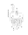
先ず、パチンコ機10の背面構成について全体の概要を説明する。パチンコ機10にはその背面(実際には内枠12及び遊技盤30の背面)において、各種制御基板が上下左右に並べられるようにして又は前後に重ねられるようにして配置されており、さらに、遊技球を供給するための遊技球供給装置(払出機構)や樹脂製の保護カバー等が取り付けられている。本実施の形態では、各種制御基板を2つの取付台に分けて搭載して2つの制御基板ユニットを構成し、それら制御基板ユニットを個別に内枠12又は遊技盤30の裏面に装着するようにしている。この場合、主基板と音声ランプ制御基板とを一方の取付台に搭載してユニット化すると共に、払出制御基板、発射制御基板及び電源基板を他方の取付台に搭載してユニット化している。ここでは便宜上、前者のユニットを「第1制御基板ユニット201」と称し、後者のユニットを「第2制御基板ユニット202」と称することとする。   First, an overall outline of the rear configuration of the pachinko machine 10 will be described. On the back surface of the pachinko machine 10 (actually, the back surface of the inner frame 12 and the game board 30), various control boards are arranged so as to be lined up and down, left and right, or stacked back and forth. A game ball supply device (payout mechanism) for supplying game balls, a protective cover made of resin, and the like are attached. In this embodiment, various control boards are divided into two mounting bases to form two control board units, and these control board units are individually attached to the inner frame 12 or the back of the game board 30. ing. In this case, the main board and the sound lamp control board are mounted on one mounting base to form a unit, and the dispensing control board, launch control board, and power supply board are mounted on the other mounting base to form a unit. Here, for convenience, the former unit is referred to as “first control board unit 201”, and the latter unit is referred to as “second control board unit 202”.

また、払出機構及び保護カバーも1ユニットとして一体化されており、一般に樹脂部分を裏パックと称することもあるため、ここではそのユニットを「裏パックユニット203」と称する。各ユニット201〜203の詳細な構成については後述する。   Further, since the dispensing mechanism and the protective cover are integrated as one unit, and the resin portion is generally referred to as a back pack, the unit is referred to as a “back pack unit 203” here. The detailed configuration of each unit 201 to 203 will be described later.

第1制御基板ユニット201、第2制御基板ユニット202及び裏パックユニット203は、ユニット単位で何ら工具等を用いずに着脱できるよう構成されており、さらにこれに加え、一部に支軸部を設けて内枠12又は遊技盤30の裏面に対して開閉できる構成となっている。これは、各ユニット201〜203やその他構成が前後に重ねて配置されても、隠れた構成等を容易に確認することを可能とするための工夫でもある。   The first control board unit 201, the second control board unit 202, and the back pack unit 203 are configured to be detachable without using any tools or the like in units of units. It is configured to be openable and closable with respect to the inner frame 12 or the back surface of the game board 30. This is also a device for making it possible to easily check a hidden configuration or the like even if the units 201 to 203 and other configurations are arranged one behind the other.

実際には、図8の概略図に示すように各ユニット201〜203が配置され、取り付けられている。なお図8において、略L字状をなす第1制御基板ユニット201はパチンコ機10のほぼ中央に配置され、その下方に第2制御基板ユニット202が配置されている。また、第1制御基板ユニット201に一部重なる領域に、裏パックユニット203が配置されている。   Actually, as shown in the schematic diagram of FIG. 8, the units 201 to 203 are arranged and attached. In FIG. 8, the first control board unit 201 having a substantially L shape is arranged at substantially the center of the pachinko machine 10, and the second control board unit 202 is arranged therebelow. Further, the back pack unit 203 is arranged in a region partially overlapping the first control board unit 201.

詳しくは、第1制御基板ユニット201には、パチンコ機10の背面から見て左端部に支軸部M1が設けられ、その支軸部M1による軸線Aを中心に当該第1制御基板ユニット201が開閉可能となっている。また、第1制御基板ユニット201には、その右端部(すなわち支軸部と反対側、さらに言えば開放端側)にナイラッチ等よりなる締結部M2が設けられると共に上端部に係止爪部M3が設けられており、これら締結部M2及び係止爪部M3によって第1制御基板ユニット201がパチンコ機本体に対して固定保持されるようになっている。   Specifically, the first control board unit 201 is provided with a support shaft part M1 at the left end portion when viewed from the back of the pachinko machine 10, and the first control board unit 201 is centered on the axis A by the support shaft part M1. It can be opened and closed. Further, the first control board unit 201 is provided with a fastening portion M2 made of a ny latch or the like at the right end portion thereof (that is, the side opposite to the support shaft portion, more specifically, the open end side), and the locking claw portion M3 at the upper end portion. The first control board unit 201 is fixedly held to the main body of the pachinko machine by the fastening part M2 and the locking claw part M3.

また、第2制御基板ユニット202には、パチンコ機10の背面から見て右端部に支軸部M4が設けられ、その支軸部M4による軸線Bを中心に当該第2制御基板ユニット202が開閉可能となっている。また、第2制御基板ユニット202には、その左端部(すなわち支軸部と反対側、さらに言えば開放端側)にナイラッチ等よりなる締結部M5が設けられており、この締結部M5によって第2制御基板ユニット202がパチンコ機本体に対して固定保持されるようになっている。   Further, the second control board unit 202 is provided with a support shaft part M4 at the right end when viewed from the back of the pachinko machine 10, and the second control board unit 202 opens and closes around the axis B by the support shaft part M4. It is possible. Further, the second control board unit 202 is provided with a fastening portion M5 made of a ny latch or the like at the left end portion thereof (that is, the side opposite to the support shaft portion, more specifically, the open end side). 2 The control board unit 202 is fixedly held to the pachinko machine body.

さらに、裏パックユニット203には、パチンコ機10の背面から見て右端部に支軸部M6が設けられ、その支軸部M6による軸線Cを中心に当該裏パックユニット203が開閉可能となっている。また、裏パックユニット203には、その左端部(すなわち支軸部と反対側、さらに言えば開放端側)にナイラッチ等よりなる締結部M7が設けられると共に上端部及び下端部にそれぞれ回動式の係止部M8,M9が設けられており、これら締結部M7及び係止部M8,M9によって裏パックユニット203がパチンコ機本体に対して固定保持されるようになっている。   Further, the back pack unit 203 is provided with a support shaft portion M6 at the right end when viewed from the back of the pachinko machine 10, and the back pack unit 203 can be opened and closed around an axis C by the support shaft portion M6. Yes. Further, the back pack unit 203 is provided with a fastening portion M7 made of a ny latch or the like at the left end portion thereof (that is, the side opposite to the support shaft portion, more specifically, the open end side), and the upper end portion and the lower end portion are respectively rotatable. , And the back pack unit 203 is fixedly held to the main body of the pachinko machine by the fastening part M7 and the locking parts M8, M9.

この場合、各ユニット201〜203の展開方向は同一でなく、第1制御基板ユニット201は、パチンコ機10の背面から見て左開きになるのに対し、第2制御基板ユニット202及び裏パックユニット203は、同右開きになるよう構成されている。   In this case, the development directions of the units 201 to 203 are not the same, and the first control board unit 201 opens to the left when viewed from the back of the pachinko machine 10, whereas the second control board unit 202 and the back pack unit. 203 is configured to open to the right.

一方、図9は、内枠12に遊技盤30を組み付けた状態でその構成を示す背面図である。また、図10は内枠12を後方より見た斜視図であり、図11は遊技盤30を後方より見た斜視図である。ここでは図9〜図11を用いて内枠12及び遊技盤30の裏面構成を説明する。   On the other hand, FIG. 9 is a rear view showing the configuration in a state where the game board 30 is assembled to the inner frame 12. FIG. 10 is a perspective view of the inner frame 12 as viewed from the rear, and FIG. 11 is a perspective view of the game board 30 as viewed from the rear. Here, the back side structure of the inner frame 12 and the game board 30 will be described with reference to FIGS.

遊技盤30は、樹脂ベース20に囲まれた四角枠状の設置領域に設置され、内枠12に設けられた複数(本実施の形態では4カ所)の係止固定具211,212によって脱落しないように固定されている。係止固定具211,212は手動で回動でき、固定位置(ロック位置)と固定解除位置(アンロック位置)とを切り換えることができるよう構成されており、図9にはロック状態を示す。遊技盤30の左右3カ所の係止固定具211は金属片を折り曲げ形成したL型の金具であり、遊技盤30の固定状態で内枠外方へ張り出さないよう構成されている。なお、遊技盤30の下部1カ所の係止固定具212は樹脂製のI型の留め具である。   The game board 30 is installed in a square frame-shaped installation area surrounded by the resin base 20 and is not dropped by a plurality of (four in this embodiment) locking fixtures 211 and 212 provided on the inner frame 12. So that it is fixed. The locking fixtures 211 and 212 can be manually rotated to switch between a fixed position (lock position) and a fixed release position (unlock position). FIG. 9 shows a locked state. The locking fixtures 211 at the three left and right sides of the game board 30 are L-shaped brackets formed by bending metal pieces, and are configured not to protrude outward from the inner frame when the game board 30 is fixed. Note that the locking fixture 212 at one lower portion of the game board 30 is an I-shaped fastener made of resin.

遊技盤30の中央には可変表示装置ユニット35が配置されている。可変表示装置ユニット35においては、センターフレーム47(図3参照)を背後から覆う樹脂製(例えばABS製)のフレームカバー213が後方に突出して設けられており、そのフレームカバー213の後端に、液晶表示装置たる表示装置42と表示制御装置45とが前後に重ねられた状態で着脱可能に取り付けられている。フレームカバー213内には、センターフレーム47に内蔵されたLED等を駆動するためのLED制御基板などが配設されている。   A variable display device unit 35 is disposed in the center of the game board 30. In the variable display device unit 35, a frame cover 213 made of resin (for example, made of ABS) that covers the center frame 47 (see FIG. 3) from behind is provided to protrude rearward, and at the rear end of the frame cover 213, A display device 42 as a liquid crystal display device and a display control device 45 are detachably attached in a state where they are overlapped in the front-rear direction. In the frame cover 213, an LED control board for driving LEDs and the like built in the center frame 47 are disposed.

また、遊技盤30の裏面には、可変表示装置ユニット35を取り囲むようにして裏枠セット215が取り付けられている。この裏枠セット215は、遊技盤30の裏面に張り付くようにして設けられる薄型の樹脂成型品(例えばABS製)であって、各種入賞口に入賞した遊技球を回収するための遊技球回収機構が形成されている。詳しくは、裏枠セット215の下方には、前述した一般入賞口31、可変入賞装置32、第1の始動口33(それぞれ図3参照)の遊技盤開口部に対応し、且つ下流側で1カ所に集合する回収通路216が形成されている。また、遊技盤30の下方には、内枠12にやはり樹脂製(例えばポリカーボネート樹脂製)の排出通路盤217が取り付けられており、該排出通路盤217には、排出球をパチンコ機10外部へ案内するための排出通路218が形成されている。従って、図9に仮想線で例示するように、一般入賞口31等に入賞した遊技球は何れも裏枠セット215の回収通路216を介して集合し、さらに排出通路盤217の排出通路218を介してパチンコ機10外部に排出される。なお、アウト口36(図3参照)も同様に排出通路218に通じており、何れの入賞口にも入賞しなかった遊技球も排出通路218を介してパチンコ機10外部に排出される。   A back frame set 215 is attached to the back surface of the game board 30 so as to surround the variable display device unit 35. The back frame set 215 is a thin resin-molded product (for example, made of ABS) provided so as to stick to the back surface of the game board 30, and a game ball collecting mechanism for collecting game balls won in various winning openings. Is formed. Specifically, below the back frame set 215, corresponding to the above-described game board opening of the general winning opening 31, the variable winning apparatus 32, and the first starting opening 33 (see FIG. 3 respectively), and 1 on the downstream side. A collection passage 216 that collects at a place is formed. Further, a discharge passage board 217 made of resin (for example, made of polycarbonate resin) is attached to the inner frame 12 below the game board 30, and a discharge ball is sent to the outside of the pachinko machine 10 in the discharge passage board 217. A discharge passage 218 for guiding is formed. Therefore, as illustrated in phantom lines in FIG. 9, all the game balls won in the general winning opening 31 etc. gather through the collection passage 216 of the back frame set 215, and further the discharge passage 218 of the discharge passage board 217. Through the pachinko machine 10. In addition, the out port 36 (see FIG. 3) similarly communicates with the discharge passage 218, and the game balls that have not won any prize opening are discharged to the outside of the pachinko machine 10 through the discharge passage 218.

上記構成では、遊技盤30の下端面を境界にして、上方に裏枠セット215(回収通路216)が、下方に排出通路盤217(排出通路218)が設けられており、排出通路盤217が遊技盤30に対して前後方向に重複(オーバーラップ)せずに設けられている。従って、遊技盤30を内枠12から取り外す際において、排出通路盤217が遊技盤取り外しの妨げになるといった不都合が生じることもない。   In the above configuration, with the lower end surface of the game board 30 as a boundary, a back frame set 215 (collection passage 216) is provided above, and a discharge passage board 217 (discharge passage 218) is provided below. The game board 30 is provided without overlapping (overlap) in the front-rear direction. Therefore, when removing the game board 30 from the inner frame 12, there is no inconvenience that the discharge passage board 217 prevents the game board from being removed.

なお、排出通路盤217は、パチンコ機前面の上皿19の丁度裏側辺りに設けられており、上皿19に至る球排出口(図2の球通路樋69)より針金等を差し込み、さらにその針金等を内枠12と排出通路盤217との隙間を通じて遊技領域側に侵入させるといった不正行為が考えられる。そこで本パチンコ機10では、排出通路盤217の上皿19の丁度裏側辺りに、内枠12にほぼ一体的に重なり合うようにしてパチンコ機前方に延びるプレート219が設けられている。従って、内枠12と排出通路盤217との隙間から針金等を侵入させようとしてもそれがプレート219にて阻害され、遊技領域にまで針金等を侵入させることが非常に困難となる。結果として、針金等を利用して可変入賞装置32(大入賞口)を強制的に開放する等の不正行為を防止することができる。   The discharge passage board 217 is provided just behind the upper plate 19 on the front surface of the pachinko machine, and a wire or the like is inserted from a ball discharge port (ball passage rod 69 in FIG. 2) leading to the upper plate 19. An illegal act of causing a wire or the like to enter the game area side through a gap between the inner frame 12 and the discharge passage board 217 can be considered. Accordingly, in the pachinko machine 10, a plate 219 extending in front of the pachinko machine so as to overlap the inner frame 12 almost integrally is provided just behind the upper plate 19 of the discharge passage board 217. Therefore, even if a wire or the like tries to enter from the gap between the inner frame 12 and the discharge passage board 217, the wire or the like is obstructed by the plate 219, and it becomes very difficult to make the wire or the like enter the game area. As a result, it is possible to prevent an illegal act such as forcibly opening the variable winning device 32 (large winning opening) using a wire or the like.

また、遊技盤30の裏面には、各種入賞口などの遊技球の通過を検出するための入賞感知機構などが設けられている。具体的には、遊技盤30表側の一般入賞口31に対応する位置には入賞口スイッチ221が設けられ、可変入賞装置32には、特定領域スイッチ222とカウントスイッチ223とが設けられている。特定領域スイッチ222は、大当たり状態で可変入賞装置32に入賞した遊技球が特定領域(大当たり状態継続を判定するための領域)に入ったことを判定するスイッチであり、カウントスイッチ223は入賞球をカウントするスイッチである。また、第1の始動口33に対応する位置には作動口スイッチ224が設けられ、第2の始動口34に対応する位置にはゲートスイッチ225が設けられている。なお、上述した作動口スイッチ224が本発明における入賞検出手段に相当する。   In addition, on the back side of the game board 30, a winning detection mechanism for detecting the passage of gaming balls such as various winning holes is provided. Specifically, a prize opening switch 221 is provided at a position corresponding to the general prize opening 31 on the front side of the game board 30, and a specific area switch 222 and a count switch 223 are provided in the variable prize winning device 32. The specific area switch 222 is a switch for determining that a game ball won in the variable winning device 32 in the big hit state has entered a specific area (an area for determining whether or not to continue the big hit state), and the count switch 223 displays the winning ball. It is a switch that counts. An operation port switch 224 is provided at a position corresponding to the first start port 33, and a gate switch 225 is provided at a position corresponding to the second start port 34. The operating port switch 224 described above corresponds to the winning detection means in the present invention.

入賞口スイッチ221及びゲートスイッチ225は、図示しない電気配線を通じて盤面中継基板226に接続され、さらにこの盤面中継基板226が後述する主基板(主制御装置)に接続されている。また、特定領域スイッチ222及びカウントスイッチ223は大入賞口中継基板227に接続され、さらにこの大入賞口中継基板227がやはり主基板に接続されている。これに対し、作動口スイッチ224は中継基板を介さずに直接主基板に接続されている。   The prize opening switch 221 and the gate switch 225 are connected to the board relay board 226 through electric wiring (not shown), and this board relay board 226 is connected to a main board (main control device) described later. Further, the specific area switch 222 and the count switch 223 are connected to the special winning opening relay board 227, and the special winning opening relay board 227 is also connected to the main board. On the other hand, the operation port switch 224 is directly connected to the main board without passing through the relay board.

その他図示は省略するが、可変入賞装置32には、大入賞口を開放するための大入賞口ソレノイドと、入賞球を特定領域に導くための入賞球振分板ソレノイドが設けられ、第1の始動口33には、電動役物を開放するための作動口ソレノイドが設けられている。なお、図9において符号228は電磁式遊技球発射部である。   Although not shown in the drawings, the variable winning device 32 is provided with a large winning opening solenoid for opening the large winning opening and a winning ball sorting plate solenoid for guiding the winning ball to a specific area. The start port 33 is provided with an operation port solenoid for opening the electric accessory. In FIG. 9, reference numeral 228 denotes an electromagnetic game ball launcher.

上記入賞感知機構にて各々検出された検出結果は、後述する主基板に取り込まれ、該主基板よりその都度の入賞状況に応じた払出指令(遊技球の払出個数)が払出制御基板に送信される。そして、該払出制御基板の出力により所定数の遊技球の払出が実施される。かかる場合、各種入賞口に入賞した遊技球を入賞球処理装置に一旦集め、その入賞球処理装置で入賞球の存在を1つずつ順番に確認した上で払出を行う従来方式(いわゆる証拠球方式)とは異なり、本実施の形態のパチンコ機10では、各種入賞口毎に遊技球の入賞を電気的に感知して払出が直ちに行われる(すなわち、本パチンコ機10では入賞球処理装置を廃止している)。故に、払い出す遊技球が多量にあっても、その払出をいち早く実施することが可能となる。但し、本発明に従来の「証拠球方式」を適用してもよい。   The detection results detected by the winning detection mechanism are taken into the main board, which will be described later, and a payout command (the number of game balls to be paid out) corresponding to the winning situation is sent from the main board to the payout control board. The Then, a predetermined number of game balls are paid out by the output of the payout control board. In such a case, a conventional method (so-called evidence ball method) in which game balls won at various winning openings are once collected in a winning ball processing device, and the winning ball processing device confirms the presence of the winning balls one by one and then pays out one by one. Unlike the above, the pachinko machine 10 according to the present embodiment electrically senses the winning of a game ball at each winning opening and immediately pays out (that is, the pachinko machine 10 abolishes the winning ball processing device). doing). Therefore, even if there are a lot of game balls to be paid out, the payout can be carried out quickly. However, the conventional “evidence ball system” may be applied to the present invention.

また、裏枠セット215には、第1制御基板ユニット201を取り付けるための取付機構が設けられている。具体的には、この取付機構として、遊技盤30の裏面から見て左下隅部には上下方向に延びる支持金具231が設けられ、この支持金具231には同一軸線上に上下一対の支持孔231aが形成されている。その他、遊技盤30の右下部において符号232は上下一対の被締結孔(ナイラッチ孔)であり、同左上部において符号233は係止爪片である。   The back frame set 215 is provided with an attachment mechanism for attaching the first control board unit 201. Specifically, as this attachment mechanism, a support bracket 231 extending in the vertical direction is provided at the lower left corner when viewed from the back surface of the game board 30, and the support bracket 231 has a pair of upper and lower support holes 231a on the same axis. Is formed. In addition, in the lower right part of the game board 30, reference numeral 232 is a pair of upper and lower fastening holes (nylatches), and in the upper left part, reference numeral 233 is a locking claw piece.

また、内枠12の裏面には、第2制御基板ユニット202や裏パックユニット203を取り付けるための取付機構が設けられている。具体的には、内枠12にはその右端部に長尺状の支持金具235が取り付けられており、その構成を図12に示す。図12に示すように、支持金具235は長尺板状の金具本体236を有し、その金具本体236より起立させるようにして、下方2カ所に第2制御基板ユニット用の支持孔部237が形成されると共に、上方2カ所に裏パックユニット用の支持孔部238が形成されている。それら支持孔部237,238にはそれぞれ同軸の支持孔が形成されている。その他、第2制御基板ユニット用の取付機構として、内枠12には、遊技盤設置領域よりも下方左端部に上下一対の被締結孔(ナイラッチ孔)239が設けられている。また、裏パックユニット用の取付機構として、内枠12には、遊技盤設置領域の左端部に上下一対の被締結孔(ナイラッチ孔)240が設けられている。但し、第2制御基板ユニット用の支持金具と裏パックユニット用の支持金具とを各々個別の部材で設けることも可能である。符号241,242,243は、遊技盤30との間に裏パックユニット203を挟み込んで支持するための回動式の固定具である。   Further, an attachment mechanism for attaching the second control board unit 202 and the back pack unit 203 is provided on the back surface of the inner frame 12. Specifically, a long support fitting 235 is attached to the inner frame 12 at its right end, and its configuration is shown in FIG. As shown in FIG. 12, the support metal fitting 235 has a long plate-like metal fitting body 236, and the support hole 237 for the second control board unit is formed at two lower positions so as to stand up from the metal fitting body 236. At the same time, support hole portions 238 for the back pack unit are formed at two locations above. Coaxial support holes are formed in the support hole portions 237 and 238, respectively. In addition, as an attachment mechanism for the second control board unit, the inner frame 12 is provided with a pair of upper and lower fastening holes (ny latch holes) 239 at the left end below the game board installation area. In addition, as an attachment mechanism for the back pack unit, the inner frame 12 is provided with a pair of upper and lower fastening holes (ny latch holes) 240 at the left end portion of the game board installation area. However, the support bracket for the second control board unit and the support bracket for the back pack unit can be provided as separate members. Reference numerals 241, 242, and 243 denote rotational fixtures for sandwiching and supporting the back pack unit 203 with the game board 30.

その他、内枠12の背面構成において、遊技盤30の右下部には、後述する払出機構部352より払い出される遊技球を上皿19、下皿15、又は排出通路218の何れかに振り分けるための遊技球分配部245が設けられている。すなわち、遊技球分配部245の開口部245aは上皿19に通じ、開口部245bは下皿15に通じ、開口部245cは排出通路218に通じる構成となっている。図10,20に示すように、遊技球分配部245は、その上方位置に位置する後述の払出機構部352とは別体としている。図10に示すように、遊技球分配部245は、内枠12にネジで締結固定されており、パチンコ機10の上皿19の排出口67(図3参照)から異物を挿入操作するなどしても動かない、つまり遊技球分配部245が奥側に押されて遊技球分配部245と内枠12との間に隙間が空くようなことが無いし、この隙間に異物を挿入するなどによる不正を防止できる。   In addition, in the rear configuration of the inner frame 12, a game ball paid out from a payout mechanism 352 described later is distributed to any one of the upper plate 19, the lower plate 15, and the discharge passage 218 in the lower right portion of the game board 30. A game ball distribution unit 245 is provided. That is, the opening 245 a of the game ball distribution unit 245 communicates with the upper plate 19, the opening 245 b communicates with the lower plate 15, and the opening 245 c communicates with the discharge passage 218. As shown in FIGS. 10 and 20, the game ball distribution unit 245 is separated from a later-described payout mechanism unit 352 located above the game ball distribution unit 245. As shown in FIG. 10, the game ball distributing unit 245 is fastened and fixed to the inner frame 12 with screws, and inserts foreign objects from the discharge port 67 (see FIG. 3) of the upper plate 19 of the pachinko machine 10. Even if the game ball distribution unit 245 is pushed to the back side, there is no gap between the game ball distribution unit 245 and the inner frame 12, and a foreign object is inserted into the gap. It can prevent fraud.

また、内枠12の下端部には、下皿15に設置されたスピーカ24の背後を囲むための樹脂製のスピーカボックス246が取り付けられており、このスピーカボックス246により低音域の音質改善が図られている。   In addition, a resin speaker box 246 for enclosing the back of the speaker 24 installed on the lower plate 15 is attached to the lower end portion of the inner frame 12. It has been.

次に、第1制御基板ユニット201を、図13〜図16を用いて説明する。図13は第1制御基板ユニット201の正面図、図14は同ユニット201の斜視図、図15は同ユニット201の分解斜視図、図16は同ユニット201を裏面から見た分解斜視図である。   Next, the first control board unit 201 will be described with reference to FIGS. 13 is a front view of the first control board unit 201, FIG. 14 is a perspective view of the unit 201, FIG. 15 is an exploded perspective view of the unit 201, and FIG. 16 is an exploded perspective view of the unit 201 viewed from the back. .

第1制御基板ユニット201は略L字状をなす取付台251を有し、この取付台251に主制御装置261と音声ランプ制御装置262とが搭載されている。ここで、主制御装置261は、主たる制御を司るCPU、遊技プログラムを記憶したROM、遊技の進行に応じた必要なデータを記憶するRAM、各種機器との連絡をとるポート、各種抽選の際に用いられる乱数発生器、時間計数や同期を図る場合などに使用されるクロックパルス発生回路等を含む主基板を具備しており、この主基板が透明樹脂材料等よりなる基板ボックス263(被包手段)に収容されて構成されている。なお、基板ボックス263は、略直方体形状のボックスベースと該ボックスベースの開口部を覆うボックスカバーとを備えている。これらボックスベースとボックスカバーとは封印ユニット264(封印手段)によって開封不能に連結され、これにより基板ボックス263が封印されている。   The first control board unit 201 includes a mounting base 251 having a substantially L shape, and the main control device 261 and the sound lamp control device 262 are mounted on the mounting base 251. Here, the main control device 261 includes a CPU that controls the main control, a ROM that stores a game program, a RAM that stores necessary data according to the progress of the game, a port that communicates with various devices, and various lotteries. A main board including a random number generator to be used, a clock pulse generation circuit used for time counting and synchronization, and the like is provided. ). The substrate box 263 includes a substantially rectangular parallelepiped box base and a box cover that covers the opening of the box base. The box base and the box cover are connected to each other by a sealing unit 264 (sealing means) so that the box box 263 is sealed.

封印手段としての封印ユニット264はボックスベースとボックスカバーとを開封不能に連結する構成であれば任意の構成が適用できるが、ここでは図14等に示すように、5つの封印部材が連結された構成となっており、この封印部材の長孔に係止爪を挿入することでボックスベースとボックスカバーとが開封不能に連結されるようになっている。封印ユニット264による封印処理は、その封印後の不正な開封を防止し、また万一不正開封が行われてもそのような事態を早期に且つ容易に発見可能とするものであって、一旦開封した後でも再度開封・封印処理を行うこと自体は可能である。すなわち、封印ユニット264を構成する5つの封印部材のうち、少なくとも一つの封印部材の長孔に係止爪を挿入することにより封印処理が行われる。そして、収容した主基板の不具合などにより基板ボックス263を開封する場合には、係止爪が挿入された封印部材と他の封印部材との連結を切断する。その後、再度封印処理する場合は他の封印部材の長孔に係止爪を挿入する。基板ボックス263の開封を行った旨の履歴を当該基板ボックス263に残しておけば、基板ボックス263を見ることで不正な開封が行われた旨が容易に発見できる。   As the sealing unit 264 as the sealing means, any configuration can be applied as long as the box base and the box cover are connected so as not to be opened, but here, as shown in FIG. 14 and the like, five sealing members are connected. The box base and the box cover are connected so that they cannot be opened by inserting a locking claw into the long hole of the sealing member. The sealing process by the sealing unit 264 prevents unauthorized opening after the sealing, and makes it possible to detect such a situation early and easily even if the unauthorized opening is performed. It is possible to perform the opening / sealing process again even after the operation. That is, the sealing process is performed by inserting the locking claw into the long hole of at least one sealing member among the five sealing members constituting the sealing unit 264. And when opening the board | substrate box 263 by the malfunction of the accommodated main board | substrate etc., the connection of the sealing member in which the latching claw was inserted, and another sealing member is cut | disconnected. Thereafter, when the sealing process is performed again, the locking claws are inserted into the long holes of the other sealing members. If the history of opening the substrate box 263 is left in the substrate box 263, it can be easily found that the unauthorized opening has been performed by looking at the substrate box 263.

また、音声ランプ制御装置262は、例えば主制御装置261(主基板)又は表示制御装置45からの指示に従い音声やランプ表示の制御を司るCPUや、その他ROM、RAM、各種ポート等を含む音声ランプ制御基板を具備しており、この音声ランプ制御基板が透明樹脂材料等よりなる基板ボックス265に収容されて構成されている。音声ランプ制御装置262上には電源中継基板266が搭載されており、後述する電源基板より供給される電源がこの電源中継基板266を介して表示制御装置45及び音声ランプ制御装置262に出力されるようになっている。   The voice lamp control device 262 is a voice lamp including a CPU that controls voice and lamp display in accordance with instructions from the main control device 261 (main board) or the display control device 45, and other ROM, RAM, various ports, and the like. The audio lamp control board is housed in a board box 265 made of a transparent resin material or the like. A power relay board 266 is mounted on the sound lamp control device 262, and power supplied from a power board described later is output to the display control device 45 and the sound lamp control device 262 via the power relay board 266. It is like that.

取付台251は、有色(例えば緑、青等)の樹脂材料(例えばポリカーボネート樹脂製)にて成形され、その表面に平坦状をなす2つの基板搭載面252,253が設けられている。これら基板搭載面252,253は直交する向きに延び、前後方向に段差をもって形成されている。但し、取付台251は無色透明又は半透明の樹脂成型品であっても良い。   The mounting base 251 is formed of a colored (for example, green, blue, etc.) resin material (for example, made of polycarbonate resin), and has two substrate mounting surfaces 252 and 253 that are flat on the surface. These substrate mounting surfaces 252 and 253 extend in a direction perpendicular to each other, and are formed with a step in the front-rear direction. However, the mounting base 251 may be a colorless transparent or translucent resin molded product.

そして、一方の基板搭載面252上に主制御装置261(主基板)が横長の向きに配置されると共に、他方の基板搭載面253上に音声ランプ制御装置262(音声ランプ制御基板)が縦長の向きに配置されるようになっている。特に、主制御装置261は、パチンコ機10裏面から見て手前側に配置され、音声ランプ制御装置262はその奥側に配置される。この場合、基板搭載面252,253が前後方向に段差をもって形成されているため、これら基板搭載面252,253に主制御装置261及び音声ランプ制御装置262を搭載した状態において各制御装置261,262はその一部を前後に重ねて配置されるようになる。つまり、図14等にも見られるように、主制御装置261はその一部(本実施の形態では1/3程度)が浮いた状態で配置されるようになる。故に、主制御装置261に重なる領域まで音声ランプ制御装置262を拡張することが可能となり、当該制御基板の大型化にも良好に対処できる。また、各制御装置が効率良く設置できるようになる。また、第1制御基板ユニット201を遊技盤30に装着した状態では、基板搭載面252の後方にスペースが確保され、可変入賞装置32やその電気配線等が無理なく設置できるようになっている。   The main control device 261 (main substrate) is arranged in a landscape orientation on one board mounting surface 252 and the audio lamp control device 262 (audio lamp control board) is arranged in a portrait orientation on the other substrate mounting surface 253. It is arranged in the direction. In particular, the main control device 261 is disposed on the near side as viewed from the back of the pachinko machine 10, and the sound lamp control device 262 is disposed on the back side. In this case, since the substrate mounting surfaces 252 and 253 are formed with steps in the front-rear direction, the control devices 261 and 262 are mounted with the main controller 261 and the sound lamp controller 262 mounted on the substrate mounting surfaces 252 and 253. Are arranged with a part of them stacked one after the other. That is, as can be seen in FIG. 14 and the like, the main controller 261 is arranged in a state where a part thereof (about 1 / in the present embodiment) is floated. Therefore, the sound lamp control device 262 can be extended to an area overlapping with the main control device 261, and the enlargement of the control board can be dealt with satisfactorily. In addition, each control device can be installed efficiently. Further, when the first control board unit 201 is mounted on the game board 30, a space is secured behind the board mounting surface 252 so that the variable winning device 32 and its electric wiring can be installed without difficulty.

図15及び図16に示すように、主基板用の基板搭載面252には、左右2カ所に横長形状の貫通孔254が形成されている。これに対応して、主制御装置261の基板ボックス263には、その裏面の左右2カ所に回動式の固定具267が設けられている。主制御装置261を基板搭載面252に搭載する際には、基板搭載面252の貫通孔254に固定具267が通され、その状態で固定具267が回動されて主制御装置261がロックされる。従って、上述の通り主制御装置261はその一部が浮いた状態で配置されるとしても、当該主制御装置261の脱落等の不都合が回避できる。また、主制御装置261は、裏パックユニット203を軸線Cを軸心として開き、第1制御基板ユニット201を軸線Aを軸心として開いた後に、この第1制御基板ユニット201(基板搭載面252)の裏面側から固定具267をロック解除しなければ、取り外しできないため、基板取り外し等の不正行為に対して抑止効果が期待できる。主基板用の基板搭載面252にはその裏面に格子状のリブ255が設けられている。   As shown in FIGS. 15 and 16, the board mounting surface 252 for the main board is formed with horizontally elongated through holes 254 at two places on the left and right. Correspondingly, the substrate box 263 of the main control device 261 is provided with rotational fixing tools 267 at two places on the left and right sides of the back surface thereof. When the main controller 261 is mounted on the board mounting surface 252, the fixing tool 267 is passed through the through hole 254 of the board mounting surface 252, and the fixing tool 267 is rotated in this state to lock the main control apparatus 261. The Therefore, even if the main control device 261 is arranged in a state where it floats as described above, inconveniences such as dropping off of the main control device 261 can be avoided. The main controller 261 opens the back pack unit 203 with the axis C as the axis and opens the first control board unit 201 with the axis A as the axis, and then the first control board unit 201 (the board mounting surface 252). ) Cannot be removed unless the lock 267 is unlocked from the back surface side, and therefore a deterrent effect can be expected for illegal actions such as board removal. A grid-like rib 255 is provided on the back surface of the substrate mounting surface 252 for the main substrate.

取付台251には、図14等の左端面に上下一対の支軸256が設けられており、この支軸256を図9等に示す支持金具231に取り付けることで、第1制御基板ユニット201が遊技盤30に対して開閉可能に支持される。また、取付台251には、右端部に締結具として上下一対のナイラッチ257が設けられると共に上端部に長孔258が設けられており、ナイラッチ257を図9等に示す被締結孔232にはめ込むと共に、長孔258に図9等に示す係止爪片233を係止させることで、第1制御基板ユニット201が遊技盤30に固定されるようになる。なお、支持金具231及び支軸256が前記図8の支軸部M1に、被締結孔232及びナイラッチ257が締結部M2に、係止爪片233及び長孔258が係止爪部M3に、それぞれ相当する。   The mounting base 251 is provided with a pair of upper and lower support shafts 256 on the left end surface of FIG. 14 and the like. By attaching the support shafts 256 to the support fitting 231 shown in FIG. The game board 30 is supported so that it can be opened and closed. Further, the mounting base 251 is provided with a pair of upper and lower nai latches 257 as fasteners at the right end portion and a long hole 258 at the upper end portion, and the nai latch 257 is fitted into the fastening hole 232 shown in FIG. The first control board unit 201 is fixed to the game board 30 by locking the locking claw pieces 233 shown in FIG. The support fitting 231 and the support shaft 256 are in the support shaft portion M1 of FIG. 8, the fastened hole 232 and the ny latch 257 are in the fastening portion M2, the locking claw piece 233 and the long hole 258 are in the locking claw portion M3, Each corresponds.

次に、第2制御基板ユニット202を、図17〜図19を用いて説明する。図17は第2制御基板ユニット202の正面図、図18は同ユニット202の斜視図、図19は同ユニット202の分解斜視図である。但し、図18では便宜上、カードユニット接続基板314が取付台301から取り外された状態を示している。   Next, the second control board unit 202 will be described with reference to FIGS. 17 is a front view of the second control board unit 202, FIG. 18 is a perspective view of the unit 202, and FIG. 19 is an exploded perspective view of the unit 202. However, FIG. 18 shows a state in which the card unit connection board 314 is removed from the mounting base 301 for convenience.

第2制御基板ユニット202は横長形状をなす取付台301を有し、この取付台301に払出制御装置311、発射制御装置312、電源装置313及びカードユニット接続基板314が搭載されている。払出制御装置311、発射制御装置312及び電源装置313は周知の通り制御の中枢をなすCPUや、その他ROM、RAM、各種ポート等を含む制御基板を具備しており、払出制御装置311の払出制御基板により、賞品球や貸出球の払出が制御される。また、発射制御装置312の発射制御基板により、遊技者による遊技球発射ハンドル18の操作に従い電磁式遊技球発射部228の制御が行われ、電源装置313の電源基板により、各種制御装置等で要する所定の電源電圧が生成され出力される。カードユニット接続基板314は、パチンコ機前面の貸球操作部120(図1参照)及び図示しないカードユニットに電気的に接続され、遊技者による球貸し操作の指令を取り込んでそれを払出制御装置311に出力するものである。なお、カードユニットを介さずに球貸し装置等から上皿に遊技球が直接貸し出される現金機では、カードユニット接続基板314は不要である。   The second control board unit 202 has a horizontally long mounting base 301 on which a payout control device 311, a firing control device 312, a power supply device 313 and a card unit connection board 314 are mounted. The payout control device 311, the launch control device 312, and the power supply device 313 are provided with a control board including a central control CPU, ROM, RAM, various ports and the like as is well known. The payout of prize balls and rental balls is controlled by the substrate. The launch control board of the launch control device 312 controls the electromagnetic game ball launcher 228 according to the operation of the game ball launch handle 18 by the player, and the power board of the power supply device 313 requires various control devices and the like. A predetermined power supply voltage is generated and output. The card unit connection board 314 is electrically connected to the ball lending operation unit 120 (see FIG. 1) on the front surface of the pachinko machine and a card unit (not shown), and receives a ball lending operation command by the player and pays it out. Is output. Note that the card unit connection board 314 is not necessary in a cash machine in which game balls are lent directly to the upper plate from a ball lending device or the like without using a card unit.

上記払出制御装置311、発射制御装置312、電源装置313及びカードユニット接続基板314は、透明樹脂材料等よりなる基板ボックス315,316,317,318にそれぞれ収容されて構成されている。特に、払出制御装置311では、前述した主制御装置261と同様、基板ボックス315(被包手段)を構成するボックスベースとボックスカバーとが封印ユニット319(封印手段)によって開封不能に連結され、これにより基板ボックス315が封印されている。   The payout control device 311, the firing control device 312, the power supply device 313, and the card unit connection substrate 314 are configured to be accommodated in substrate boxes 315, 316, 317, and 318 made of a transparent resin material, respectively. In particular, in the dispensing control device 311, similarly to the main control device 261 described above, the box base and the box cover constituting the substrate box 315 (encapsulating means) are connected by the sealing unit 319 (sealing means) so that they cannot be opened. Thus, the substrate box 315 is sealed.

払出制御装置311には状態復帰スイッチ321が設けられている。例えば、払出モータ部の球詰まり等、払出エラーの発生時において状態復帰スイッチ321が押下されると、払出モータが正逆回転され、球詰まりの解消(正常状態への復帰)が図られるようになっている。   The payout control device 311 is provided with a state return switch 321. For example, when the state return switch 321 is pressed when a payout error occurs, such as a ball clogged in the payout motor unit, the payout motor is rotated forward and reverse so that the ball clogging is eliminated (return to the normal state). It has become.

また、電源装置313にはRAM消去スイッチ323が設けられている。本パチンコ機10はバックアップ機能を有しており、万一停電が発生した際でも停電時の状態を保持し、停電からの復帰(復電)の際には停電時の状態に復帰できるようになっている。従って、通常手順で(例えばホールの営業終了時に)電源遮断すると電源遮断前の状態が記憶保持されることから、電源投入時に初期状態に戻したい場合には、RAM消去スイッチ323を押しながら電源を投入することとしている。   Further, the power supply device 313 is provided with a RAM erase switch 323. This pachinko machine 10 has a backup function, so that even if a power failure occurs, it maintains the state at the time of a power failure, and can be restored to the state at the time of a power failure when returning from a power failure (power recovery) It has become. Therefore, if the power is turned off in the normal procedure (for example, when the hall is closed), the state before the power is turned off is stored and retained. We are going to throw it in.

取付台301は例えば無色透明な樹脂成型品よりなり、その表面に平坦状をなす基板搭載面302が設けられている。この場合、発射制御装置312、電源装置313及びカードユニット接続基板314は取付台301の基板搭載面302に横並びの状態で直接搭載され、電源装置313の基板ボックス317上に払出制御装置311が搭載されている。   The mounting base 301 is made of, for example, a colorless and transparent resin molded product, and a flat board mounting surface 302 is provided on the surface thereof. In this case, the launch control device 312, the power supply device 313 and the card unit connection board 314 are directly mounted side by side on the board mounting surface 302 of the mounting base 301, and the payout control apparatus 311 is mounted on the board box 317 of the power supply apparatus 313. Has been.

また、取付台301には、図17等の右端部に上下一対の支軸305が設けられており、この支軸305を図9等に示す支持孔部237に上方から挿通させることで、第2制御基板ユニット202が内枠12に対して開閉可能に支持される。また、取付台301には、左端部に締結具として上下一対のナイラッチ306が設けられており、ナイラッチ306を図9等に示す被締結孔239にはめ込むことで、第2制御基板ユニット202が内枠12に開閉不能に固定されるようになる。なお、支持孔部237及び支軸305が前記図8の支軸部M4に、被締結孔239及びナイラッチ306が締結部M5に、それぞれ相当する。   Further, the mounting base 301 is provided with a pair of upper and lower support shafts 305 at the right end in FIG. 17 and the like. By inserting these support shafts 305 into the support hole 237 shown in FIG. 2 The control board unit 202 is supported to be openable and closable with respect to the inner frame 12. In addition, the mounting base 301 is provided with a pair of upper and lower nai latches 306 as fasteners at the left end portion. By fitting the nai latch 306 into the fastening hole 239 shown in FIG. It is fixed to the frame 12 so that it cannot be opened and closed. The support hole portion 237 and the support shaft 305 correspond to the support shaft portion M4 in FIG. 8, and the fastened hole 239 and the ny latch 306 correspond to the fastening portion M5, respectively.

次に、裏パックユニット203の構成を説明する。裏パックユニット203は、樹脂成形された裏パック351と遊技球の払出機構部352とを一体化したものであり、裏パックユニット203の正面図を図20に示し、分解斜視図を図21に示す。   Next, the configuration of the back pack unit 203 will be described. The back pack unit 203 is formed by integrating a resin-molded back pack 351 and a game ball payout mechanism 352. FIG. 20 shows a front view of the back pack unit 203 and FIG. 21 shows an exploded perspective view thereof. Show.

裏パック351は例えばABS樹脂により一体成型されており、略平坦状のベース部353と、パチンコ機後方に突出し横長の略直方体形状をなす保護カバー部354とを有する。保護カバー部354は左右側面及び上面が閉鎖され且つ下面のみが開放された形状をなし、少なくとも可変表示装置ユニット35を囲むのに十分な大きさを有する(但し本実施の形態では、前述の音声ランプ制御装置262も合わせて囲む構成となっている)。保護カバー部354の背面には多数の通気孔354aが設けられている。この通気孔354aは各々が長孔状をなし、それぞれの通気孔354aが比較的近い位置で隣り合うよう設けられている。従って、隣り合う通気孔354a間にある樹脂部分を切断することにより、裏パック351の背面を容易に開口させることができる。つまり、通気孔354a間の樹脂部分を切断してその内部の表示制御装置45等を露出させることで、所定の検定等を容易に実施することができる。   The back pack 351 is integrally formed of, for example, ABS resin, and includes a substantially flat base portion 353 and a protective cover portion 354 that protrudes rearward of the pachinko machine and has a horizontally long substantially rectangular parallelepiped shape. The protective cover portion 354 has a shape in which the left and right side surfaces and the upper surface are closed and only the lower surface is opened, and has a size sufficient to surround at least the variable display device unit 35 (however, in the present embodiment, the sound The lamp control device 262 is also enclosed. A large number of ventilation holes 354 a are provided on the back surface of the protective cover portion 354. Each of the air holes 354a has a long hole shape, and the air holes 354a are adjacent to each other at a relatively close position. Therefore, the back surface of the back pack 351 can be easily opened by cutting the resin portion between the adjacent vent holes 354a. That is, a predetermined test or the like can be easily performed by cutting the resin portion between the vent holes 354a to expose the display control device 45 and the like inside.

また、ベース部353には、保護カバー部354を迂回するようにして払出機構部352が配設されている。すなわち、裏パック351の最上部には上方に開口したタンク355が設けられており、このタンク355には遊技ホールの島設備から供給される遊技球が逐次補給される。タンク355の下方には、例えば横方向2列(2条)の球通路を有し下流側に向けて緩やかに傾斜するタンクレール356が連結され、さらにタンクレール356の下流側には縦向きにケースレール357が連結されている。払出装置358はケースレール357の最下流部に設けられ、払出モータ等の所定の電気的構成により必要個数の遊技球の払出が適宜行われる。そして、払出装置358より払い出された遊技球は図21に示す払出通路359等を通じて前記上皿19に供給される。   In addition, a payout mechanism 352 is disposed on the base 353 so as to bypass the protective cover 354. That is, a tank 355 that opens upward is provided at the top of the back pack 351, and game balls supplied from the island facilities of the game hall are sequentially replenished to the tank 355. Below the tank 355, for example, a tank rail 356 having two lateral rows (two strips) of ball passages and being gently inclined toward the downstream side is connected. Further, the tank rail 356 is vertically oriented downstream of the tank rail 356. A case rail 357 is connected. The payout device 358 is provided at the most downstream portion of the case rail 357, and a required number of game balls are paid out appropriately according to a predetermined electrical configuration such as a payout motor. The game balls paid out from the payout device 358 are supplied to the upper plate 19 through the payout passage 359 and the like shown in FIG.

タンクレール356と、当該タンクレール356に振動を付加するためのバイブレータ360とが一体化となるようにユニット化されている。つまり、バイブレータ360が例えば2本のネジでタンクレール356に締結されて取り付けられるようになっている。さらに、バイブレータ360は、タンクレール356に面接触するのではなく、当該2本のネジの部分で接触するようになっており、バイブレータ360による振動がより効果的にタンクレール356に伝わるようになっている。従って、仮にタンクレール356付近で球詰まりが生じた際、バイブレータ360が駆動されることで球詰まりが解消されるようになっている。   The tank rail 356 and the vibrator 360 for applying vibration to the tank rail 356 are unitized so as to be integrated. That is, the vibrator 360 is fastened and attached to the tank rail 356 with, for example, two screws. Further, the vibrator 360 does not come into surface contact with the tank rail 356 but comes into contact with the two screw portions, so that the vibration by the vibrator 360 is more effectively transmitted to the tank rail 356. ing. Therefore, if a clogged ball occurs near the tank rail 356, the clogged ball is eliminated by driving the vibrator 360.

タンクレール356の構成について詳述すると、図22に示すように、タンクレール356は上方に開口した長尺樋状をなすレール本体361を有し、レール本体361の始端部には球面状の球受部362が設けられている。この球受部362により、タンク355より落下してきた遊技球が円滑にレール本体361内に取り込まれる。また、レール本体361には長手方向に延びる仕切壁363が設けられており、この仕切壁363により遊技球が二手に分流されるようになっている。仕切壁363により仕切られた2条の球通路は遊技球の直径よりも僅かに幅広となっている。仕切壁363により仕切られた各球通路の底面には、1筋又は2筋の突条364が設けられると共に、その突条364の側方に開口部365が設けられている。   The configuration of the tank rail 356 will be described in detail. As shown in FIG. 22, the tank rail 356 has a rail body 361 having a long bowl shape opened upward, and a spherical ball is formed at the start end of the rail body 361. A receiving part 362 is provided. By this ball receiving portion 362, the game ball dropped from the tank 355 is smoothly taken into the rail body 361. Further, the rail body 361 is provided with a partition wall 363 extending in the longitudinal direction, and the game balls are divided into two hands by the partition wall 363. The two ball passages partitioned by the partition wall 363 are slightly wider than the diameter of the game ball. One or two ridges 364 are provided on the bottom surface of each spherical passage partitioned by the partition wall 363, and an opening 365 is provided on the side of the ridge 364.

また、レール本体361には、その下流側半分程度の天井部分を覆うようにして整流板367が配設されている。この整流板367は、下流側になるほどタンクレール356内の球通路高さを制限するよう弓なりに反った形状をしており、さらにその下面には長手方向に延びる凸部368が形成されている。これにより、タンクレール356内を流れる各遊技球は最終的には上下に積み重なることなく下流側に流出する。従って、タンクレール356に多量の遊技球群が流れ込んできても、遊技球の噛み込みが防止され、タンクレール356内における球詰まりが解消されるようになっている。なお、レール本体361が黒色の導電性ポリカーボネート樹脂により成形されるのに対し、整流板367は透明のポリカーボネート樹脂により成形されている。整流板367は着脱可能に設けられており、当該整流板367を取り外すことによりタンクレール356内のメンテナンスが容易に実施できるようになっている。   In addition, a rectifying plate 367 is disposed on the rail body 361 so as to cover the ceiling portion of the downstream half. The rectifying plate 367 has a bowed shape so as to limit the height of the ball passage in the tank rail 356 toward the downstream side, and a convex portion 368 extending in the longitudinal direction is formed on the lower surface thereof. . Thereby, each game ball flowing in the tank rail 356 finally flows out downstream without being stacked up and down. Therefore, even if a large group of game balls flow into the tank rail 356, the game balls are prevented from being bitten and the ball clogging in the tank rail 356 is eliminated. The rail body 361 is formed of a black conductive polycarbonate resin, whereas the rectifying plate 367 is formed of a transparent polycarbonate resin. The rectifying plate 367 is detachably provided. By removing the rectifying plate 367, maintenance in the tank rail 356 can be easily performed.

図20,21の説明に戻り、払出機構部352には、払出制御装置311から払出装置358への払出指令の信号を中継する払出中継基板381が設置されると共に、外部より主電源を取り込むための電源スイッチ基板382が設置されている。電源スイッチ基板382には、電圧変換器を介して例えば交流24Vの主電源が供給され、電源スイッチ382aの切替操作により電源ON又は電源OFFとされるようになっている。   Returning to the description of FIGS. 20 and 21, the payout mechanism unit 352 is provided with a payout relay board 381 that relays a payout command signal from the payout control device 311 to the payout device 358, and takes in the main power from outside. The power switch board 382 is installed. The power switch board 382 is supplied with, for example, an AC 24V main power via a voltage converter, and is turned on or off by a switching operation of the power switch 382a.

タンク355から払出通路359に至るまでの払出機構部352は何れも導電性を有する樹脂材料(例えば導電性ポリカーボネート樹脂)にて成形され、その一部にてアースされている。これにより、遊技球の帯電によるノイズの発生が抑制されるようになっている。   All of the dispensing mechanism 352 from the tank 355 to the dispensing passage 359 is formed of a conductive resin material (for example, conductive polycarbonate resin) and grounded at a part thereof. Thereby, generation | occurrence | production of the noise by charging of a game ball is suppressed.

また、裏パック351には、図20等の右端部に上下一対の支軸385が設けられており、この支軸385を図9等に示す支持孔部238に上方から挿通させることで、裏パックユニット203が内枠12に対して開閉可能に支持される。また、裏パック351には、左端部に締結具として上下一対のナイラッチ386が設けられると共に、上端部に係止孔387が設けられており、ナイラッチ386を図9等に示す被締結孔240にはめ込むと共に、係止孔387に図9等に示す固定具242を係止させることで、裏パックユニット203が内枠12に開閉不能に固定されるようになる。このとき、図9等に示す固定具241,243によっても裏パックユニット203が内枠12に固定される。なお、支持孔部238及び支軸385が前記図8の支軸部M6に、被締結孔240及びナイラッチ386が締結部M7に、固定具242及び係止孔387が係止部M8に、それぞれ相当する。また、固定具243が係止部M9に相当する。   Further, the back pack 351 is provided with a pair of upper and lower support shafts 385 at the right end in FIG. 20 and the like, and the support shaft 385 is inserted into the support hole 238 shown in FIG. The pack unit 203 is supported so as to be openable and closable with respect to the inner frame 12. In addition, the back pack 351 is provided with a pair of upper and lower nai latches 386 as fasteners at the left end portion, and a locking hole 387 is provided at the upper end portion. The nai latch 386 is inserted into the tightened hole 240 shown in FIG. The back pack unit 203 is fixed to the inner frame 12 so that it cannot be opened and closed by engaging the fixing hole 387 shown in FIG. At this time, the back pack unit 203 is also fixed to the inner frame 12 by the fixtures 241 and 243 shown in FIG. The support hole portion 238 and the support shaft 385 are provided in the support shaft portion M6 of FIG. Equivalent to. Further, the fixture 243 corresponds to the locking portion M9.

なお、図6,図20に示すように、内枠12の右上側には、内枠12が外枠11に対して開かれたことを検出する内枠開検出スイッチ388が設けられている。内枠12が開かれると、内枠開検出スイッチ388からホール内(パチンコ店内)用コンピュータへ出力されるようになっている。   As shown in FIGS. 6 and 20, an inner frame open detection switch 388 for detecting that the inner frame 12 is opened with respect to the outer frame 11 is provided on the upper right side of the inner frame 12. When the inner frame 12 is opened, it is output from the inner frame opening detection switch 388 to the computer for the hall (in the pachinko parlor).

なお、図9に示すように、裏パックユニット203は、被締結孔240及びナイラッチ386と、固定具241,242とによって、内枠12の裏面に着脱自在に取り付けられている。このように固定具241,242も用いているので、タンク355に供給される遊技球の重みで裏パックユニット203が内枠12から外れてしまうことを防止している。   As shown in FIG. 9, the back pack unit 203 is detachably attached to the back surface of the inner frame 12 by a fastening hole 240, a ny latch 386, and fixtures 241 and 242. Since the fixtures 241 and 242 are also used in this way, the back pack unit 203 is prevented from being detached from the inner frame 12 due to the weight of the game balls supplied to the tank 355.

次に、本パチンコ機10の電気的構成について、図23を用いて説明する。図23は、本パチンコ機10の電気的構成を示したブロック図である。本パチンコ機10は、主制御装置261と、払出制御装置311と、発射制御装置312と、表示制御装置45と、電源装置313などを備えている。以下に、これらの装置を個別に詳細に説明する。   Next, the electrical configuration of the pachinko machine 10 will be described with reference to FIG. FIG. 23 is a block diagram showing an electrical configuration of the pachinko machine 10. The pachinko machine 10 includes a main control device 261, a payout control device 311, a launch control device 312, a display control device 45, a power supply device 313, and the like. In the following, these devices will be described in detail individually.

パチンコ機10の主制御装置261には、演算装置である1チップマイコンとしてのCPU501が搭載されている。CPU501には、該CPU501により実行される各種の制御プログラムや固定値データを記憶したROM502と、そのROM502内に記憶される制御プログラムの実行に際して各種のデータ等を一時的に記憶するためのメモリであるRAM503と、割込回路やタイマ回路、データ送受信回路などの各種回路が内蔵されている。   The main controller 261 of the pachinko machine 10 is equipped with a CPU 501 as a one-chip microcomputer that is an arithmetic unit. The CPU 501 includes a ROM 502 that stores various control programs executed by the CPU 501 and fixed value data, and a memory that temporarily stores various data when the control program stored in the ROM 502 is executed. A certain RAM 503 and various circuits such as an interrupt circuit, a timer circuit, and a data transmission / reception circuit are incorporated.

RAM503は、パチンコ機10の電源のオフ後においても電源装置313からバックアップ電圧が供給されてデータが保持(バックアップ)できる構成となっており、RAM503には、各種のデータ等を一時的に記憶するためのメモリやエリアの他に、バックアップエリア503aが設けられている。   The RAM 503 is configured so that data can be retained (backed up) by being supplied with a backup voltage from the power supply device 313 even after the power of the pachinko machine 10 is turned off. The RAM 503 temporarily stores various data and the like. In addition to the memory and area for this purpose, a backup area 503a is provided.

バックアップエリア503aは、停電などの発生により電源が切断された場合において、電源の再入時にパチンコ機10の状態を電源切断前の状態に復帰させるべく、電源切断時(停電発生時を含む。以下同様)のスタックポインタや、各レジスタ、I/O等の値を記憶しておくためのエリアである。バックアップエリア503aへの書き込みは、NMI割込み処理(図33参照)によって電源切断時に実行され、逆にバックアップエリア503aに書き込まれた各値の復帰は、電源入時(停電解消による電源入を含む。以下同様)の復電処理において実行される。なお、CPU501のNMI端子(ノンマスカブル割込端子)には、停電等の発生による電源断時に、後述する停電監視回路542から出力される停電信号S1が入力されるように構成されており、停電の発生により、図33の停電処理(NMI割込み処理)が即座に実行される。   In the backup area 503a, when the power is cut off due to a power failure or the like, the power of the pachinko machine 10 is restored to the state before the power is turned off when the power is turned on again. This is an area for storing stack pointers, values of registers, I / O, and the like. Writing to the backup area 503a is executed when the power is turned off by NMI interrupt processing (see FIG. 33). Conversely, returning of each value written to the backup area 503a includes turning on the power (including turning on the power due to power failure cancellation). The same applies to the following power recovery process. The N501 terminal (non-maskable interrupt terminal) of the CPU 501 is configured to receive a power failure signal S1 output from a power failure monitoring circuit 542, which will be described later, when a power failure occurs due to the occurrence of a power failure or the like. Due to the occurrence, the power failure process (NMI interrupt process) of FIG. 33 is immediately executed.

かかるROM502及びRAM503を内蔵したCPU501には、アドレスバス及びデータバスで構成されるバスライン504を介して入出力ポート505が接続されている。入出力ポート505には、後述するRAM消去スイッチ回路643、払出制御装置311、表示制御装置45や、その他図示しないスイッチ群などが接続されている。   An input / output port 505 is connected to the CPU 501 incorporating the ROM 502 and RAM 503 via a bus line 504 including an address bus and a data bus. The input / output port 505 is connected to a RAM erasing switch circuit 643, a payout control device 311, a display control device 45, and a switch group (not shown).

また、払出制御装置311は、払出モータにより賞球や貸し球の払出制御を行うものである。演算装置であるCPU511は、そのCPU511により実行される制御プログラムや固定値データ等を記憶したROM512と、ワークメモリ等として使用されるRAM513とを備えている。   The payout control device 311 controls payout of prize balls and rental balls by a payout motor. The CPU 511 that is an arithmetic unit includes a ROM 512 that stores a control program executed by the CPU 511, fixed value data, and the like, and a RAM 513 that is used as a work memory or the like.

払出制御装置311のRAM513は、前述した主制御装置261のRAM503と同様に、パチンコ機10の電源のオフ後においても電源装置313からバックアップ電圧が供給されてデータが保持(バックアップ)できる構成となっており、RAM513には、各種のデータ等を一時的に記憶するためのメモリやエリアの他に、バックアップエリア513aが設けられている。   The RAM 513 of the payout control device 311 is configured to hold (backup) data by supplying a backup voltage from the power supply device 313 even after the pachinko machine 10 is turned off, like the RAM 503 of the main control device 261 described above. The RAM 513 is provided with a backup area 513a in addition to a memory and an area for temporarily storing various data.

バックアップエリア513aは、停電などの発生により電源が切断された場合において、電源の再入時にパチンコ機10の状態を電源切断前の状態に復帰させるべく、電源切断時のスタックポインタや、各レジスタ、I/O等の値を記憶しておくためのエリアである。このバックアップエリア513aへの書き込みは、NMI割込み処理(図33参照)によって電源切断時に実行され、逆にバックアップエリア513aに書き込まれた各値の復帰は、電源入時の復電処理において実行される。   The backup area 513a has a stack pointer, each register at the time of power off, each register, so that the power of the pachinko machine 10 is restored to the state before the power is turned off when the power is turned off. This is an area for storing values such as I / O. The writing to the backup area 513a is executed when the power is turned off by the NMI interrupt process (see FIG. 33), and the return of each value written to the backup area 513a is executed in the power recovery process when the power is turned on. .

かかるROM512及びRAM513を内蔵したCPU511には、アドレスバス及びデータバスで構成されるバスライン514を介して入出力ポート515が接続されている。入出力ポート515には、RAM消去スイッチ回路543、主制御装置261、発射制御装置312、払出モータ358aなどがそれぞれ接続されている。   An input / output port 515 is connected to the CPU 511 incorporating the ROM 512 and the RAM 513 through a bus line 514 including an address bus and a data bus. A RAM erase switch circuit 543, a main control device 261, a firing control device 312, a payout motor 358a, and the like are connected to the input / output port 515, respectively.

発射制御装置312は、電磁式遊技球発射部228による遊技球の発射を許可又は禁止するものであり、電磁式遊技球発射部228は、所定条件が整っている場合に駆動が許可される。具体的には、払出制御装置311から発射許可信号が出力されていること、遊技者が遊技球発射ハンドル18をタッチしていることをセンサ信号により検出していること、発射を停止させるための発射停止スイッチが操作されていないことを条件に、電磁式遊技球発射部228が駆動され、遊技球発射ハンドル18の操作量に応じた強度で遊技球が発射される。   The launch control device 312 permits or prohibits the game ball launching by the electromagnetic game ball launching unit 228, and the electromagnetic game ball launching unit 228 is allowed to drive when a predetermined condition is met. Specifically, it is detected by a sensor signal that a firing permission signal is output from the payout control device 311, that the player is touching the game ball launch handle 18, and the launch is stopped. On condition that the firing stop switch is not operated, the electromagnetic game ball launching unit 228 is driven, and the game ball is launched with an intensity corresponding to the operation amount of the game ball launch handle 18.

表示制御装置45は、表示装置42の第1図柄表示部43aにおける第1図柄の変動表示と、表示装置42の第2図柄表示部43bにおける第2図柄の変動表示とを制御するものである。この表示制御装置45は、CPU521と、ROM(プログラムROM)522と、ワークRAM523と、ビデオRAM524と、キャラクタROM525と、画像コントローラ526と、入力ポート527と、2つの出力ポート528,529と、バスライン530,531とを備えている。入力ポート527の入力には主制御装置261の出力が接続され、入力ポート527の出力には、CPU521、ROM522、ワークRAM523、画像コントローラ526が接続されると共にバスライン530を介して一方の出力ポート528が接続されている。出力ポート528の出力には音声ランプ制御装置262が接続されている。また、画像コントローラ526にはバスライン531を介して出力ポート529が接続されており、その出力ポート529の出力には液晶表示装置である表示装置42が接続されている。   The display control device 45 controls the variation display of the first symbol on the first symbol display unit 43a of the display device 42 and the variation display of the second symbol on the second symbol display unit 43b of the display device 42. The display control device 45 includes a CPU 521, a ROM (program ROM) 522, a work RAM 523, a video RAM 524, a character ROM 525, an image controller 526, an input port 527, two output ports 528 and 529, and a bus. Lines 530 and 531 are provided. The output of the main controller 261 is connected to the input of the input port 527, and the CPU 521, ROM 522, work RAM 523, and image controller 526 are connected to the output of the input port 527 and one output port is connected via the bus line 530. 528 is connected. An audio lamp control device 262 is connected to the output of the output port 528. Further, an output port 529 is connected to the image controller 526 via a bus line 531, and a display device 42 which is a liquid crystal display device is connected to an output of the output port 529.

表示制御装置45のCPU521は、主制御装置261から送信される表示コマンドに基づいて表示装置42の表示を制御する。ROM522は、そのCPU521により実行される各種の制御プログラムや固定値データを記憶するためのメモリであり、ワークRAM523は、CPU521による各種プログラムの実行時に使用されるワークデータやフラグを一時的に記憶するためのメモリである。   The CPU 521 of the display control device 45 controls the display of the display device 42 based on the display command transmitted from the main control device 261. The ROM 522 is a memory for storing various control programs executed by the CPU 521 and fixed value data, and the work RAM 523 temporarily stores work data and flags used when the CPU 521 executes various programs. It is a memory for.

ビデオRAM524は、表示装置42に表示される表示データを記憶するためのメモリであり、このビデオRAM524の内容を書き替えることにより、表示装置42の表示内容が変更される。キャラクタROM525は、表示装置42に表示される図柄などのキャラクタデータを記憶するためのメモリである。画像コントローラ526は、CPU521、ビデオRAM524、出力ポート529のそれぞれのタイミングを調整してデータの読み書きに介在すると共に、ビデオRAM524に記憶される表示データを、キャラクタROM525から所定のタイミングで読み出して表示装置42に表示させるものである。   The video RAM 524 is a memory for storing display data displayed on the display device 42, and the display content of the display device 42 is changed by rewriting the content of the video RAM 524. The character ROM 525 is a memory for storing character data such as symbols displayed on the display device 42. The image controller 526 adjusts the timings of the CPU 521, the video RAM 524, and the output port 529 to intervene in reading and writing data, and reads display data stored in the video RAM 524 from the character ROM 525 at a predetermined timing. 42 is displayed.

また、電源装置313は、パチンコ機10の各部に電力を供給するための電源部541と、停電等による電源遮断を監視する停電監視回路542と、RAM消去スイッチ323に接続されてなるRAM消去スイッチ回路543とを備えている。電源部541は、図示しない電源経路を通じて、主制御装置261や払出制御装置311等に対して各々に必要な動作電源を供給する。その概要としては、電源部541は、外部より供給される交流24ボルト電源を取り込み、各種スイッチやモータ等を駆部するための+12V電源、ロジック用の+5V電源、RAMバックアップ用のバックアップ電源などを生成し、これら+12V電源、+5V電源及びバックアップ電源を主制御装置261や払出制御装置311等に対して供給する。なお、発射制御装置312に対しては払出制御装置311を介して動作電源(+12V電源、+5V電源等)が供給される。   The power supply unit 313 includes a power supply unit 541 for supplying power to each part of the pachinko machine 10, a power failure monitoring circuit 542 for monitoring power interruption due to a power failure, and a RAM erase switch connected to the RAM erase switch 323. A circuit 543. The power supply unit 541 supplies necessary operation power to the main control device 261, the payout control device 311 and the like through a power supply path (not shown). As an outline, the power supply unit 541 takes in an AC 24 volt power supply supplied from the outside, and supplies a + 12V power supply for driving various switches, motors, etc., a + 5V power supply for logic, a backup power supply for RAM backup, and the like. The + 12V power source, the + 5V power source, and the backup power source are supplied to the main control device 261, the payout control device 311 and the like. Note that operation power (+12 V power, +5 V power, etc.) is supplied to the launch control device 312 via the payout control device 311.

停電監視回路542は、停電等の発生による電源断時に、主制御装置261のCPU501及び払出制御装置311のCPU511の各NMl端子へ停電信号S1を出力するための回路である。停電監視回路542は、電源部541で交流5ボルトの電圧を監視し、この電圧が5ボルト未満になった時間が例えば20ミリ秒を超えた場合に停電(電源断)の発生と判断して、停電信号S1を主制御装置261及び払出制御装置311へ出力する。この停電信号S1の出力によって、主制御装置261及び払出制御装置311は、停電の発生を認識し、停電時処理(図33のNMI割込み処理)を実行する。   The power failure monitoring circuit 542 is a circuit for outputting a power failure signal S1 to each NMl terminal of the CPU 501 of the main control device 261 and the CPU 511 of the payout control device 311 when the power is cut off due to the occurrence of a power failure or the like. The power failure monitoring circuit 542 monitors the voltage of AC 5 volts in the power supply unit 541, and determines that a power failure (power failure) has occurred when the time when this voltage has become less than 5 volts exceeds, for example, 20 milliseconds. The power failure signal S1 is output to the main controller 261 and the payout controller 311. Based on the output of the power failure signal S1, the main control device 261 and the payout control device 311 recognize the occurrence of the power failure and execute the power failure processing (NMI interrupt processing in FIG. 33).

なお、電源部541は、電源部541で監視している交流5ボルトが5ボルト未満となった時間が20ミリ秒を越えた後においても、かかる停電時処理の実行に充分な時間の間、制御系の駆動電圧である5ボルトの出力を正常値に維持するように構成されている。よって、主制御装置261及び払出制御装置311は、停電時処理を正常に実行し完了することができる。   In addition, even after the time when the AC 5 volts monitored by the power supply unit 541 becomes less than 5 volts exceeds 20 milliseconds, the power supply unit 541 has a sufficient time to execute the power failure process. The control system is configured to maintain the output of 5 volts, which is the drive voltage of the control system, at a normal value. Therefore, the main control device 261 and the payout control device 311 can normally execute and complete the power failure process.

RAM消去スイッチ回路543は、RAM消去スイッチ323のスイッチ信号を取り込み、そのスイッチ323の状態に応じて主制御装置261のRAM503及び払出制御装置311のRAM513のバックアップデータをクリアするための回路である。RAM消去スイッチ323が押下された際、RAM消去スイッチ回路543は、RAM消去信号S2を主制御装置261及び払出制御装置311に出力する。RAM消去スイッチ323が押下された状態でパチンコ機10の電源が投入されると(停電解消による電源入を含む)、主制御装置261及び払出制御装置311においてそれぞれのRAM503,613のデータがクリアされる。   The RAM erase switch circuit 543 is a circuit for taking in the switch signal of the RAM erase switch 323 and clearing backup data in the RAM 503 of the main controller 261 and the RAM 513 of the payout controller 311 in accordance with the state of the switch 323. When the RAM erase switch 323 is pressed, the RAM erase switch circuit 543 outputs a RAM erase signal S2 to the main controller 261 and the payout controller 311. When the power of the pachinko machine 10 is turned on with the RAM erase switch 323 pressed (including power-on due to power failure cancellation), the data in the respective RAMs 503 and 613 are cleared in the main controller 261 and the payout controller 311. The

ところで、表示装置(液晶表示装置)42には、図24に示すように、左・中・右の3つの図柄列L,M,Rが設定されており、図柄列L,M,R毎に上図柄、中図柄、下図柄の3個ずつの図柄(第1図柄:例えば特別図柄)が変動表示される。本実施の形態では、一連の図柄は、「0」〜「9」の数字を各々付した主図柄と、菱形状の絵図柄からなる副図柄とにより構成されており、数字の昇順又は降順に主図柄が表示されると共に各主図柄の間に副図柄が配されて一連の図柄列L,M,Rが構成されている。そして、周期性を持って主図柄と副図柄が上から下へと変動表示されるようになっている。   By the way, as shown in FIG. 24, the display device (liquid crystal display device) 42 is provided with three symbol rows L, M, and R of left, middle, and right. Three symbols of the upper symbol, the middle symbol, and the lower symbol (the first symbol: for example, a special symbol) are variably displayed. In the present embodiment, the series of symbols is composed of a main symbol with numbers “0” to “9” and a sub-pattern consisting of rhombus-shaped symbols, in ascending or descending order of the numbers. A main symbol is displayed, and a sub-symbol is arranged between the main symbols to form a series of symbol rows L, M, and R. The main symbol and the sub symbol are variably displayed from top to bottom with periodicity.

かかる場合、左図柄列Lにおいては、上記一連の図柄が降順(すなわち、主図柄の番号が減る順)に表示され、中図柄列M及び右図柄列Rにおいては、同じく上記一連の図柄が昇順(すなわち、主図柄の番号が増える順)に表示される。そして、左図柄列L→右図柄列R→中図柄列Mの順に変動表示が停止し、その停止時に第1図柄表示襲置42上の5つの有効ライン、すなわち上ラインL1、中ラインL2、下ラインL3、右上がりラインL4、左上がりラインL5の何れかで主図柄が大当たり図柄の組合せ(本実施の形態では、同一の主図柄の組合せ)で揃えば大当たりとして特別遊技動画が表示されるようになっている。   In this case, in the left symbol row L, the series of symbols is displayed in descending order (that is, in the order of decreasing the number of the main symbol), and in the middle symbol row M and the right symbol row R, the series of symbols is also in ascending order. (That is, in order of increasing main symbol numbers). Then, the variable display stops in the order of the left symbol row L → the right symbol row R → the middle symbol row M, and at the time of the stop, five effective lines on the first symbol display raid 42, that is, the upper line L1, the middle line L2, A special game video is displayed as a jackpot if the main symbol is aligned with a jackpot symbol combination (in this embodiment, the same main symbol combination) in any of the lower line L3, the rightward rising line L4, and the leftward rising line L5. It is like that.

次に、上記の如く構成されたパチンコ機10の動作について説明する。   Next, the operation of the pachinko machine 10 configured as described above will be described.

本実施の形態では、主制御装置261内のCPU501は、遊技に際し各種カウンタ情報を用いて表示装置42の抽選(大当たり抽選)や図柄表示の設定などを行うこととしており、具体的には、図25に示すように、表示装置42の大当たりの抽選に使用する大当たり乱数カウンタC1と、表示装置42の大当たり図柄の選択に使用する大当たり図柄カウンタC2と、表示装置42が外れ変動する際のリーチ抽選に使用するリーチ乱数カウンタC3と、大当たり乱数カウンタC1の初期値設定に使用する乱数初期値カウンタCINIと、表示装置42の変動パターン選択に使用する変動種別カウンタCS1,CS2と、左列、中列及び右列の各外れ図柄の設定に使用する左・中・右の各外れ図柄カウンタCL,CM,CRとを用いることとしている。上述した各カウンタは、CPU501で実行されるプログラムにより構成されている。   In this embodiment, the CPU 501 in the main control device 261 performs lottery (big hit lottery) of the display device 42 and setting of symbol display using various counter information in the game. 25, the jackpot random number counter C1 used for the jackpot lottery of the display device 42, the jackpot symbol counter C2 used for the selection of the jackpot symbol of the display device 42, and the reach lottery when the display device 42 changes and changes Reach random number counter C3 used for initial value, random number initial value counter CINI used for initial value setting of jackpot random number counter C1, variation type counters CS1 and CS2 used for variation pattern selection of display device 42, left column, middle column And the left, middle and right out symbol counters CL, CM, CR used to set each out symbol in the right column; To have. Each counter described above is constituted by a program executed by the CPU 501.

このうち、カウンタC1〜C3,CINI,CS1,CS2は、その更新の都度、前回値に「1」が加算され(以下、「更新」という)、最大値に達した後「0」に戻るループカウンタとなっている。また、外れ図柄カウンタCL,CM,CRは、CPU501内のRレジスタ(リフレッシュレジスタ)を用いてレジスタ値が加算され、結果的に数値がランダムに変化する構成となっている。各カウンタは定期的に更新され、その更新値がRAM503の所定領域に設定されたカウンタ用バッファに適宜格納される。また、RAM503には、1つの実行エリアと4つの保留エリア(保留第1〜第4エリア)とからなる保留球格納エリアが設けられており、これらの各エリアには、第1の始動口33への遊技球の入賞履歴に合わせて、大当たり乱数カウンタC1、大当たり図柄カウンタC2及びリーチ乱数カウンタC3の各値が時系列的に格納されるようになっている。   Among these, the counters C1 to C3, CINI, CS1 and CS2 each have a loop in which “1” is added to the previous value (hereinafter referred to as “update”) and returns to “0” after reaching the maximum value. It is a counter. Further, the out symbol counters CL, CM, CR are configured such that register values are added using an R register (refresh register) in the CPU 501, and as a result, numerical values change randomly. Each counter is periodically updated, and the updated value is appropriately stored in a counter buffer set in a predetermined area of the RAM 503. The RAM 503 is provided with a holding ball storage area including one execution area and four holding areas (holding first to fourth areas). In each of these areas, the first start port 33 is provided. Each value of the jackpot random number counter C1, the jackpot symbol counter C2 and the reach random number counter C3 is stored in time series in accordance with the winning history of the game balls.

各カウンタについて詳しくは、大当たり乱数カウンタC1は、例えば「0」〜「676」の範囲内で順に「1」ずつ加算され、最大値(つまり「676」)に達した後「0」に戻る構成となっている。特に大当たり乱数カウンタC1が1周した場合、その時点の乱数初期値カウンタCINIの値が当該大当たり乱数カウンタC1の初期値として読み込まれる。なお、乱数初期値カウンタCINIは、大当たり乱数カウンタC1と同様のループカウンタであり(値=0〜676)、タイマ割込み毎に1回更新されると共に通常処理の残余時間内で綴り返し更新される。大当たり乱数カウンタC1は定期的に(本実施の形態ではタイマ割込み毎に1回)更新され、遊技球が第1の始動口33に入賞したタイミングでRAM503の保留球格納エリアに格納される。大当たりとなる乱数の値の数は、低確率時と高確率時とで2種類設定されており、低確率時に大当たりとなる乱数の値の個数は2で、その値は「337,673」であり、高確率時に大当たりとなる乱数の値の個数は10で、その値は 「67,131,199,289,337,401,463,523,601,661」である。なお、高確率時とは、予め定められた確率変動図柄によって大当たりになり付加価値としてその後の大当たり確率がアップした状態、いわゆる「確変」の時をいい、通常時(低確率時)とはそのような確変状態でない時をいう。   For details of each counter, the jackpot random number counter C1 is, for example, sequentially incremented by “1” within a range of “0” to “676” and returns to “0” after reaching the maximum value (that is, “676”). It has become. In particular, when the jackpot random number counter C1 makes one round, the value of the random number initial value counter CINI at that time is read as the initial value of the jackpot random number counter C1. The random number initial value counter CINI is a loop counter similar to the big hit random number counter C1 (value = 0 to 676), and is updated once for each timer interruption and updated repeatedly within the remaining time of normal processing. . The jackpot random number counter C1 is updated periodically (once every timer interruption in this embodiment) and stored in the reserved ball storage area of the RAM 503 at the timing when the game ball wins the first start port 33. The number of random number values that are jackpots is set at low probability and high probability, and the number of random number values that are jackpots at low probability is 2, and the value is “337,673”. There are 10 random numbers that are big hits at high probability, and the values are “67, 131, 199, 289, 337, 401, 463, 523, 601, 661”. High probability means a state where the jackpot is won by a predetermined probability variation pattern and the subsequent jackpot probability is increased as added value, so-called “probability”, and normal time (low probability) is This is the time when it is not in a probable state.

大当たり図柄カウンタC2は、大当たりの際、表示装置42の変動停止時の図柄を決定するものであり、本実施の形態では、表示装置42において有効ラインが5ラインであり、特定図柄(主図柄)が10通り設定されていることから、50個(0〜49)のカウンタ値が用意されている。すなわち、大当たり図柄カウンタC2は、0〜49の範囲内で順に1ずつ加算され、最大値(つまり49)に達した後0に戻る構成となっている。大当たり図柄カウンタC2は定期的に(本実施の形態ではタイマ割込み毎に1回)更新され、遊技球が第1の始動口33に入賞したタイミングでRAM503の保留球格納エリアに格納される。   The jackpot symbol counter C2 determines the symbol at the time when the fluctuation of the display device 42 is stopped in the case of a jackpot. In the present embodiment, the display device 42 has five effective lines, and a specific symbol (main symbol). Since 10 are set, 50 counter values (0 to 49) are prepared. In other words, the jackpot symbol counter C2 is configured so that one by one is added in order within the range of 0 to 49, and after reaching the maximum value (that is, 49), it returns to 0. The jackpot symbol counter C2 is updated periodically (once every timer interruption in this embodiment), and stored in the reserved ball storage area of the RAM 503 at the timing when the game ball wins the first start port 33.

また、リーチ乱数カウンタC3は、例えば0〜238の範囲内で順に1ずつ加算され、最大値(つまり238)に達した後0に戻る構成となっている。本実施の形態では、リーチ乱数カウンタC3によって、リーチ発生した後最終停止図柄がリーチ図柄の前後に1つだけずれて停止する「前後外れリーチ」と、同じくリーチ発生した後最終停止図柄がリーチ図柄の前後以外で停止する「前後外れ以外リーチ」と、リーチ発生しない「完全外れ」とを抽選することとしており、例えば、C3=0,1が前後外れリーチに該当し、C3=2〜21が前後外れ以外リーチに該当し、C3=22〜238が完全外れに該当する。なお、リーチの抽通は、表示装置42の抽選確率の状態や変動開始時の作動保留球数等に応じて各々個別に設定されるものであっても良い。リーチ乱数カウンタC3は定期的に(本実施の形態ではタイマ割込み毎に1回)更新され、遊技球が第1の始動口33に入賞したタイミングでRAM503の保留球格納エリアに格納される。   Further, the reach random number counter C3 is configured to increment one by one within a range of 0 to 238, for example, and returns to 0 after reaching the maximum value (that is, 238). In the present embodiment, the reach random number counter C3 causes the final stop symbol after the occurrence of reach to stop by shifting the last stop symbol by one before and after the reach symbol, and the final stop symbol after the occurrence of reach also reaches the reach symbol. “Reach other than front / rear off” that stops other than before and “completely out” that does not generate reach, for example, C3 = 0, 1 corresponds to front / rear reach, and C3 = 2-21 It corresponds to reach other than front / rear detachment, and C3 = 22 to 238 corresponds to complete detachment. The reach drawing may be set individually according to the state of the lottery probability of the display device 42, the number of operation suspension balls at the start of the change, and the like. The reach random number counter C3 is updated periodically (once every timer interruption in this embodiment) and stored in the reserved ball storage area of the RAM 503 at the timing when the game ball wins the first start port 33.

また、2つの変動種別カウンタCS1,CS2のうち、一方の変動種別カウンタCS1は、例えば0〜198の範囲内で順に1ずつ加算され、最大値(つまり198)に達した後0に戻る構成となっており、他方の変動種別カウンタCS2は、例えば0〜240の範囲内で順に1ずつ加算され、最大値(つまり240)に達した後0に戻る構成となっている。以下の説明では、CS1を「第1変動種別カウンタ」、CS2を「第2変動種別カウンタ」ともいう。第1変動種別カウンタCS1によって、いわゆるノーマルリーチ、スーパーリーチ、プレミアムリーチ等、第1図柄のリーチ種別やその他大まかな図柄変動態様が決定され、第2変動種別カウンタCS2によって、リーチ発生後に最終停止図柄(本実施の形態では中図柄)が停止するまでの経過時間(言い換えれば、変動図柄数)などより細かな図柄変動態様が決定される。従って、これらの変動種別カウンタCS1,CS2を組み合わせることで、変動パターンの多種多様化を容易に実現できる。また、第1変動種別カウンタCS1だけで図柄変動態様を決定したり、第1変動種別カウンタCS1と停止図柄との組み合わせで同じく図柄変動態様を決定したりすることも可能である。   Further, one of the two variation type counters CS1 and CS2 is incremented by one within a range of 0 to 198, for example, and reaches a maximum value (that is, 198) and then returns to 0. For example, the other variation type counter CS2 is incremented one by one within a range of 0 to 240, for example, and reaches the maximum value (that is, 240) and then returns to 0. In the following description, CS1 is also referred to as “first variation type counter”, and CS2 is also referred to as “second variation type counter”. The first variation type counter CS1 determines the reach type of the first symbol, such as so-called normal reach, super reach, premium reach, and other rough symbol variation modes. The second variation type counter CS2 determines the final stop symbol ( In the present embodiment, a more detailed symbol variation mode such as an elapsed time (in other words, the number of variation symbols) until the middle symbol) stops is determined. Therefore, a variety of variation patterns can be easily realized by combining these variation type counters CS1 and CS2. It is also possible to determine the symbol variation mode only by the first variation type counter CS1, or to determine the symbol variation mode similarly by combining the first variation type counter CS1 and the stop symbol.

変動種別カウンタCS1,CS2は、後述する通常処理が1回実行される毎に1回更新され、当該通常処理内の残余時間内でも繰り返し更新される。そして、表示装置42による第1図柄の変動開始時における変動パターン決定に際してCS1,CS2のバッファ値が取得される。   The variation type counters CS1 and CS2 are updated once every time a normal process to be described later is executed once, and are repeatedly updated even within the remaining time in the normal process. Then, the buffer values of CS1 and CS2 are acquired when the display device 42 determines the variation pattern when the first symbol variation starts.

左・中・右の各外れ図柄カウンタCL,CM,CRは、表示装置42の大当たり抽選が外れとなった時に左列第1図柄、中列第1図柄、右列第1図柄の停止図柄(外れ図柄)を決定するためのものであり、各列では主図柄及び副図柄の合わせて20の第1図柄の何れかが表示されることから、各々に20個(0〜19)のカウンタ値が用意されている。外れ図柄カウンタCLにより左図柄列の上・中・下段の各図柄が決定され、外れ図柄カウンタCMにより中図柄列の上・中・下段の各図柄が決定され、外れ図柄カウンタCRにより右図柄列の上・中・下段の各図柄が決定される。   The left, middle, and right out symbol counters CL, CM, and CR are stopped symbols (the first symbol in the left column, the first symbol in the middle column, and the first symbol in the right column when the big win lottery of the display device 42 is lost. Since each of the main symbols and sub-designs is displayed in each column, one of the 20 first symbols is displayed in each column, so 20 counter values (0 to 19) each. Is prepared. The left, upper, middle and lower symbols are determined by the out symbol counter CL, the upper, middle and lower symbols are determined by the out symbol counter CM, and the right symbol column is determined by the out symbol counter CR. The top, middle and bottom symbols are determined.

本実施の形態では、CPU501に内蔵のRレジスタの数値を用いることにより各カウンタCL,CM,CRの値をランダムに更新する構成としている。すなわち、各外れ図柄カウンタCL,CM,CRの更新時には、前回値にRレジスタの下位3ビットの値が加算され、その加算給果が最大値を超えた場合に20減算されて今回値が決定される。各外れ図柄カウンタCL,CM,CRは更新時期が重ならないようにして通常処理内で更新され、それら外れ図柄カウンタCL,CM,CRの組み合わせが、RAM503の前後外れリーチ図柄バッファ、前後外れ以外リーチ図柄バッファ及び完全外れ図柄バッファの何れかに格納される。そして、第1図柄の変動開始時における変動パターン決定に際し、リーチ乱数カウンタC3の値に応じて前後外れリーチ図柄バッファ、前後外れ以外リーチ図柄バッファ及び完全外れ図柄バッファの何れかのバッファ値が取得される。   In the present embodiment, the values of the counters CL, CM, and CR are randomly updated by using the value of the R register built in the CPU 501. That is, when each outlier symbol counter CL, CM, CR is updated, the lower 3 bits of the R register are added to the previous value, and when the added result exceeds the maximum value, 20 is subtracted to determine the current value. Is done. Each outlier symbol counter CL, CM, CR is updated within the normal process so that the update times do not overlap, and the combination of these outlier symbol counters CL, CM, CR is the reach of the RAM 503 front / rear reach symbol buffer, reach other than front / rear out It is stored in either the symbol buffer or the completely off symbol buffer. Then, when determining the variation pattern at the start of variation of the first symbol, the buffer value of any one of the front and rear outreach symbol buffer, the reach symbol buffer other than front and rear outlier and the completely out symbol symbol buffer is acquired according to the value of the reach random number counter C3. The

各カウンタの大きさや範囲は一例にすぎず任意に変更できる。但し、大当たり乱数カウンタC1、リーチ乱数カウンタC3、変動種別カウンタCS1,CS2の大きさは何れも異なる素数とし、いかなる場合にも同期しない数値としておくのが望ましい。   The size and range of each counter is only an example and can be arbitrarily changed. However, it is desirable that the big hit random number counter C1, the reach random number counter C3, and the variation type counters CS1 and CS2 are all different prime numbers and are not synchronized in any case.

また図示は省略するが、表示装置42の第2図柄表示部43bの第2図柄の抽選には第2図柄乱数カウンタC4が用いられる。第2図柄乱数カウンタC4は、例えば0〜250の範囲内で順に1ずつ加算され、最大値(つまり250)に達した後0に戻るループカウンタとして構成されている。第2図柄乱数カウンタC4は定期的に(本実施の形態ではタイマ割込み毎に1回)更新され、遊技球が左右何れかの第2の始動口34を通過した時に取得される。当選することとなる乱数の値の数は149あり、その範囲は「5〜153」である。   Although not shown, the second symbol random number counter C4 is used for the lottery of the second symbol of the second symbol display unit 43b of the display device 42. The second symbol random number counter C4 is configured as a loop counter that is incremented one by one within a range of 0 to 250, for example, and returns to 0 after reaching the maximum value (that is, 250). The second symbol random number counter C4 is periodically updated (once every timer interruption in the present embodiment), and is acquired when the game ball passes through the second start port 34 on either the left or right side. The number of random number values to be won is 149, and the range is “5 to 153”.

次いで、主制御装置261内のCPU501により実行される各制御処理を図26〜図37のフローチャートを参照しながら説明する。かかるCPU501の処理としては大別して、電源投入に伴い起動されるメイン処理と、定期的に(本実施の形態では2msec周期で)起動されるタイマ割込み処理と、NMl端子(ノンマスカブル端子)への停電信号の入力により起動されるNMI割込み処理とがあり、説明の便宜上ここでは、先ずタイマ割込み処理とNMI割込み処理とを説明し、その後でメイン処理を税明する。   Next, each control process executed by the CPU 501 in the main controller 261 will be described with reference to the flowcharts of FIGS. The processing of the CPU 501 is broadly divided into a main processing that is started when the power is turned on, a timer interrupt processing that is started periodically (in this embodiment at a cycle of 2 msec), and a power failure to the NMl terminal (non-maskable terminal). There is an NMI interrupt process activated by signal input. For convenience of explanation, the timer interrupt process and the NMI interrupt process will be described first, and then the main process will be taxed.

図31は、タイマ割込み処理を示すフローチャートであり、本処理は主制御装置261のCPU501により例えば2msec毎に実行される。   FIG. 31 is a flowchart showing the timer interrupt process. This process is executed by the CPU 501 of the main controller 261 every 2 msec, for example.

図31において、先ずステップS601では、各種入賞スイッチの読み込み処理を実行する。すなわち、主制御装置261に接続されている各種スイッチ(但し、RAM消去スイッチ323を除く)の状態を読み込むと共に、当該スイッチの状態を判定して検出情報(入賞検知情報)を保存する。   In FIG. 31, first, in step S601, reading processing of various winning switches is executed. That is, the state of various switches (except for the RAM erase switch 323) connected to the main controller 261 is read, and the state of the switch is determined and the detection information (winning detection information) is stored.

その後、ステップS602では、乱数初期値カウンタCINIの更新を実行する。具体的には、乱数初期値カウンタCINIを1インクリメントすると共に、そのカウンタ値が最大値(本実施の形態では676)に達した際0にクリアする。そして、乱数初期値カウンタCINIの更新値を、RAM503の該当するバッファ領域に格納する。また、続くステップS603では、大当たり乱数カウンタC1、大当たり図柄カウンタC2及びリーチ乱数カウンタC3の更新を実行する。具体的には、大当たり乱数カウンタC1、大当たり図柄カウンタC2及びリーチ乱数カウンタC3をそれぞれ1インクリメントすると共に、それらのカウンタ値が最大値(本実施の形態ではそれぞれ、676,49,238)に達した際それぞれ0にクリアする。そして、各カウンタC1〜C3の更新値を、RAM503の該当するバッファ領域に格納する。   Thereafter, in step S602, the random number initial value counter CINI is updated. Specifically, the random number initial value counter CINI is incremented by 1 and cleared to 0 when the counter value reaches the maximum value (676 in this embodiment). Then, the update value of the random number initial value counter CINI is stored in the corresponding buffer area of the RAM 503. In subsequent step S603, the big hit random number counter C1, the big hit symbol counter C2, and the reach random number counter C3 are updated. Specifically, the jackpot random number counter C1, the jackpot symbol counter C2, and the reach random number counter C3 are each incremented by 1 and their counter values reach the maximum values (in this embodiment, 676, 49, and 238, respectively). Clear to 0 each. Then, the updated values of the counters C1 to C3 are stored in the corresponding buffer area of the RAM 503.

その後、ステップS604では、第1の始動口33への入賞に伴う始動入賞処理を実行する。この始動入賞処理を図32のフローチャートにより説明すると、ステップS701では、遊技球が第1の始動口33に入賞したか否かを作動口スイッチ224の検出情報により判別する。遊技球が第1の始動口33に入賞したと判別されると、続くステップS702では、表示装置42の作動保留球数Nが上限値(本実施の形態では4)未満であるか否かを判別する。第1の始動口33への入賞があり、且つ作動保留球数N<4であることを条件にステップS703に進み、作動保留球数Nを1インクリメントする。   Thereafter, in step S604, a start winning process associated with winning in the first start port 33 is executed. This start winning process will be described with reference to the flowchart of FIG. 32. In step S701, whether or not the game ball has won the first start opening 33 is determined based on the detection information of the operation opening switch 224. When it is determined that the game ball has won the first start opening 33, in the subsequent step S702, it is determined whether or not the number N of operation pending balls of the display device 42 is less than the upper limit value (4 in the present embodiment). Determine. The process proceeds to step S703 on the condition that there is a winning at the first start port 33 and the number N of activated balls is <4, and the number N of activated balls is incremented by one.

また、続くステップS704では、第1図柄の当落に関わる乱数を取得する。具体的には、前記ステップS603で更新した大当たり乱数カウンタC1、大当たり図柄カウンタC2及びリーチ乱数カウンタC3の各値を、RAM503の保留球格納エリアの空き記憶エリアのうち最初のエリアに格納する。このように始動入賞処理をした後、CPU501は本タイマ割込処理を一旦終了する。   In subsequent step S704, a random number related to the winning of the first symbol is acquired. Specifically, the values of the jackpot random number counter C1, the jackpot symbol counter C2 and the reach random number counter C3 updated in step S603 are stored in the first area of the free storage area of the reserved ball storage area of the RAM 503. After performing the start winning process in this way, the CPU 501 once ends the timer interrupt process.

図33は、NMI割込み処理を示すフローチャートであり、本処理は、主制御装置261のCPU501により停電の発生等によるパチンコ機10の電源断時に実行される。このNMI割込みにより、電源断時の主制御装置261の状態がRAM503のバックアップエリア503aに記憶される。   FIG. 33 is a flowchart showing the NMI interrupt process, and this process is executed by the CPU 501 of the main control device 261 when the power of the pachinko machine 10 is cut off due to the occurrence of a power failure or the like. By this NMI interruption, the state of the main controller 261 at the time of power-off is stored in the backup area 503a of the RAM 503.

すなわち、停電の発生等によりパチンコ機10の電源が遮断されると、停電信号S1が停電監視回路542から主制御装置261内のCPU501のNMI端子に出力される。すると、CPU501は実行中の制御を中断して図33のNMI割込み処理を開始する。図33のNMI割込み処理は、主制御装置261のROM502に記憶されている。停電信号S1が出力された後所定時間は、主制御装置261の処理が実行可能となるように電源部541から電源供給がなされており、この所定時間内にNMI割込み処理が実行される。   That is, when the power of the pachinko machine 10 is cut off due to the occurrence of a power failure or the like, the power failure signal S1 is output from the power failure monitoring circuit 542 to the NMI terminal of the CPU 501 in the main controller 261. Then, the CPU 501 interrupts the control being executed and starts the NMI interrupt process of FIG. 33 is stored in the ROM 502 of the main controller 261. For a predetermined time after the power failure signal S1 is output, power is supplied from the power supply unit 541 so that the processing of the main controller 261 can be executed, and the NMI interrupt processing is executed within the predetermined time.

図33のNMI割込み処理において、先ずステップS801では、使用レジスタをRAM503のバックアップエリア503aに退避し、続くステップS802では、スタックポインタの値を同バックアップエリア503aに記憶する。さらに、ステップS803では、電源断の発生情報をバックアップエリア503aに設定し、ステップS804では、電源が速断されたことを示す電源断通知コマンドを他の制御装置に対して送信する。   In the NMI interrupt processing of FIG. 33, first, in step S801, the used registers are saved in the backup area 503a of the RAM 503, and in the subsequent step S802, the value of the stack pointer is stored in the backup area 503a. Further, in step S803, the information on the occurrence of power interruption is set in the backup area 503a, and in step S804, a power interruption notification command indicating that the power has been rapidly interrupted is transmitted to another control device.

ステップS805ではRAM判定値を算出し、バックアップエリア503aに保存する。RAM判定値は、例えば、RAM503の作業領域アドレスにおけるチェックサム値である。ステップS806では、RAMアクセスを禁止する。その後は、電源が完全に遮断して処理が実行できなくなるのに備え、無限ループに入る。   In step S805, a RAM determination value is calculated and stored in the backup area 503a. The RAM determination value is, for example, a checksum value at the work area address of the RAM 503. In step S806, RAM access is prohibited. After that, an infinite loop is entered in preparation for the case where the power supply is completely shut down and processing cannot be executed.

なお、上記のNMI割込み処理は払出制御装置311でも同様に実行され、かかるNMI割込みにより、停電の発生等による電源断時の払出制御装置311の状態がRAM513のバックアップエリア513aに記憶される。停電信号S1が出力された後所定時間は、払出制御装置311の処理が実行可能となるように電源部541から電源供給がなされるのも同様である。すなわち、停電の発生等によりパチンコ機10の電源が遮断されると、停電信号S1が停電監視回路542から払出制御装置311内のCPU511のNMl端子に出力され、CPU511は実行中の制御を中断して図33のNMI割込み処理を開始する。その内容は図33で説明した通りである(但し、この払出制御装置311のNMI割込み処理ではステップS804の電源断通知コマンドの送信はない)。   The NMI interrupt process is also executed in the payout control device 311 in the same manner, and the state of the payout control device 311 when the power is cut off due to the occurrence of a power failure or the like is stored in the backup area 513a of the RAM 513. Similarly, the power is supplied from the power supply unit 541 so that the processing of the payout control device 311 can be executed for a predetermined time after the power failure signal S1 is output. That is, when the power of the pachinko machine 10 is cut off due to the occurrence of a power failure or the like, the power failure signal S1 is output from the power failure monitoring circuit 542 to the NMl terminal of the CPU 511 in the payout control device 311 and the CPU 511 interrupts the control being executed. The NMI interrupt process of FIG. 33 is started. The contents are as described with reference to FIG. 33 (however, the NMI interrupt processing of the payout control device 311 does not transmit the power-off notification command in step S804).

次に、メイン処理について説明する。   Next, the main process will be described.

図26は、主制御装置261内のCPU501により実行されるメイン処理の一例を示すフローチャートであり、このメイン処理は電源投入時のリセットに伴い起動される。   FIG. 26 is a flowchart showing an example of a main process executed by the CPU 501 in the main control device 261. This main process is started upon reset when power is turned on.

先ず、ステップS101では、電源投入に伴う初期設定処理を実行する。具体的には、スタックポインタに予め決められた所定値を設定すると共に、サブ側の制御装置(音声ランプ制御装置262、払出制御装置311等)が動作可能な状態になるのを待つために例えば1秒程度、ウエイト処理を実行する。また、ステップS102では、払出制御装置311に対して払出許可コマンドを送信し、続くステップS103では、RAMアクセスを許可する。   First, in step S101, an initial setting process associated with power-on is executed. Specifically, in order to set a predetermined value in the stack pointer and wait for the sub-side control devices (such as the sound lamp control device 262 and the payout control device 311) to become operable, for example, Wait processing is performed for about 1 second. In step S102, a payout permission command is transmitted to the payout control device 311. In subsequent step S103, RAM access is permitted.

その後、CPU501内のRAM503に関してデータバックアップの処理を実行する。つまり、ステップS104では、電源装置313に設けたRAM消去スイッチ323が押下(ON)されているか否かを判別し、続くステップS105では、RAM503のバックアップエリア503aに電源断の発生情報が設定されているか否かを判別する。また、ステップS106ではRAM判定値を算出し、続くステップS107では、そのRAM判定値が電源断時に保存したRAM判定値と一致するか否か、すなわちバックアップの有効性を判別する。RAM判定値は、例えばRAM503の作業領域アドレスにおけるチェックサム値である。なお、RAM503の所定のエリアに書き込まれたキーワードが正しく保存されているか否かによりバックアップの有効性を判断することも可能である。   Thereafter, data backup processing is executed for the RAM 503 in the CPU 501. That is, in step S104, it is determined whether or not the RAM erase switch 323 provided in the power supply device 313 is pressed (ON). In subsequent step S105, the information on occurrence of power interruption is set in the backup area 503a of the RAM 503. It is determined whether or not. In step S106, a RAM determination value is calculated. In subsequent step S107, it is determined whether or not the RAM determination value matches the RAM determination value stored when the power is turned off, that is, the validity of the backup. The RAM determination value is a checksum value at a work area address of the RAM 503, for example. Note that it is possible to determine the effectiveness of backup based on whether or not the keywords written in a predetermined area of the RAM 503 are correctly stored.

上述したように、本パチンコ機10では、例えばホールの営業開始時など、電源投入時に初期状態に戻したい場合にはRAM消去スイッチ323を押しながら電源が投入される。従って、RAM消去スイッチ323がONされていれば、RAMの初期化処理(ステップS114等)に移行する。また、電源断の発生情報が設定されていない場合や、RAM判定値(チェックサム値等)によりバックアップの異常が確認された場合も同様にRAM503の初期化処理(ステップS114等)に移行する。つまり、ステップS114ではRAM503の使用領域を0にクリアし、続くステップS115ではRAM503の初期化処理を実行する。また、ステップS116では割込み許可を設定し、後述する通常処理に移行する。   As described above, the pachinko machine 10 is turned on while pressing the RAM erase switch 323 when it is desired to return to the initial state when the power is turned on, for example, when the hall starts business. Therefore, if the RAM erase switch 323 is ON, the process proceeds to a RAM initialization process (step S114, etc.). Similarly, when the information on occurrence of power interruption is not set, or when a backup abnormality is confirmed by a RAM determination value (checksum value or the like), the process proceeds to initialization processing of the RAM 503 (step S114 or the like). That is, in step S114, the used area of the RAM 503 is cleared to 0, and in the subsequent step S115, initialization processing of the RAM 503 is executed. In step S116, interrupt permission is set, and the process proceeds to normal processing described later.

一方、RAM消去スイッチ323が押されていない場合には、電源断の発生情報が設定されていること、及びRAM判定値(チェックサム値等)が正常であることを条件に、復電時の処理(電源断復旧時の処理)を実行する。つまり、ステップS108では、電源断前のスタックポインタを復帰させ、ステップS109では、電源断の発生情報をクリアする。ステップS110では、サブ側の制御装置を電源断時の遊技状態に複帰させるためのコマンドを送信し、ステップS111では、使用レジスタをRAM503のバックアップエリア503aから復帰させる。さらに、ステップS112,S113では、割込み許可/不許可を電源断前の状態に復帰させた後、電源断前の番地へ戻り、それから後述する通常処理(図27参照)に移行する。例えば、通常処理のステップS202まで実行されて電源断となった場合には、電源断前の番地へ戻り、通常処理のステップS203から実行されることになる。   On the other hand, if the RAM erase switch 323 has not been pressed, the power-off occurrence information is set, and the RAM judgment value (checksum value, etc.) is normal. Execute the process (process when power is restored). That is, in step S108, the stack pointer before the power interruption is restored, and in step S109, the information on the occurrence of the power interruption is cleared. In step S110, a command for causing the sub control device to return to the gaming state at the time of power-off is transmitted, and in step S111, the used register is restored from the backup area 503a of the RAM 503. Further, in steps S112 and S113, the interrupt permission / non-permission is returned to the state before the power is turned off, then the address is returned to the address before the power is turned off, and then the normal processing (see FIG. 27) described later is performed. For example, when the power is cut off after executing up to step S202 of the normal process, the process returns to the address before the power is cut off, and the process is executed from step S203 of the normal process.

次に、通常処理の流れを図27のフローチャートを参照しながら説明する。この通常処理では遊技の主要な処理が実行される。その概要として、ステップS201〜S207の処理が4msec周期の定期処理として実行され、その残余時間でステップS209,S210のカウンタ更新処理が実行される構成となっている。   Next, the flow of normal processing will be described with reference to the flowchart of FIG. In this normal process, the main process of the game is executed. As an outline, the processing of steps S201 to S207 is executed as a periodic processing with a period of 4 msec, and the counter update processing of steps S209 and S210 is executed with the remaining time.

図27において、先ずステップS201では、前回の処理で更新されたコマンド等の出力データをサブ側の各制御装置に送信する。具体的には、入賞検知情報の有無を判別し、入賞検知情報があれば払出制御装置311に対して獲得遊技球数に対応する賞球払出コマンドを送信する。また、表示装置42による第1図柄の変動表示に際して停止図柄コマンド、変動パターンコマンド、確定コマンド等を表示制御装置45に送信する。なお、第1図柄の変動開始後において、変動パ夕ーンコマンド→左図柄列の停止図柄コマンド→右図柄列の停止図柄コマンド→中図柄列の停止図柄コマンドの順で通常処理の都度1つずつ(すなわち、4msec毎に1つずつ)コマンドが送出され、変動時間経過のタイミングで確定コマンドが送出されるようになっている。   In FIG. 27, first, in step S201, output data such as a command updated in the previous process is transmitted to each control device on the sub side. Specifically, the presence / absence of winning detection information is determined, and if there is winning detection information, a winning ball payout command corresponding to the number of acquired game balls is transmitted to the payout control device 311. Further, a stop symbol command, a variation pattern command, a confirmation command, and the like are transmitted to the display control device 45 when the display device 42 displays the variation of the first symbol. In addition, after the first symbol variation starts, the variable pattern command → the left symbol sequence stop symbol command → the right symbol sequence stop symbol command → the middle symbol sequence stop symbol command one by one in the order of normal processing ( In other words, one command is sent every 4 msec), and the confirmation command is sent at the timing when the fluctuation time elapses.

次に、ステップS202では、変動種別カウンタCS1,CS2の更新を実行する。具体的には、変動種別カウンタCS1,CS2を1インクリメントすると共に、それらのカウンタ値が最大値(本実施の形態では198,240)に達した際それぞれ0にクリアする。そして、変動種別カウンタCS1,CS2の更新値を、RAM503の該当するバッファ領域に格納する。続くステップS203では、左図柄列、中図柄列及び右図柄列の各外れ図柄カウンタCL,CM,CRの更新を実行する。   Next, in step S202, the variation type counters CS1 and CS2 are updated. Specifically, the variation type counters CS1 and CS2 are incremented by 1, and are cleared to 0 when the counter values reach the maximum values (198 and 240 in this embodiment). Then, the update values of the variation type counters CS1 and CS2 are stored in the corresponding buffer area of the RAM 503. In subsequent step S203, updating of each outlier symbol counter CL, CM, CR of the left symbol row, the middle symbol row, and the right symbol row is executed.

各外れ図柄カウンタCL,CM,CRの更新処理を詳しく説明すると、図28に示すように、ステップS301では、左図柄列の外れ図柄カウンタCLの更新時期か否かを判別し、ステップS302では、中図柄列の外れ図柄カウンタCMの更新時期か否かを判別する。そして、左図柄列の更新時期(ステップS301がYES)であればステップS303に進み、左図柄列の外れ図柄カウンタCLを更新する。また、中図柄列の更新時期(ステップS302がYES)であればステップS304に進み、中図柄列の外れ図柄カウンタCMを更新する。さらに、右図柄列の更新時期(ステップS301,S302が共にNO)であればステップS305に進み、右図柄例の外れ図柄カウンタCRを更新する。ステップS303〜S305の外れ図柄カウンタCL,CM,CRの更新では、前回のカウンタ値にRレジスタの下位3ビットの値を加算すると共にその加算結果が最大値を超えた場合に20を減算し、その演算結果を外れ図柄カウンタCL,CM,CRの今回値とする。   The update process of each out symbol counter CL, CM, CR will be described in detail. As shown in FIG. 28, in step S301, it is determined whether or not it is time to update the out symbol counter CL in the left symbol row. In step S302, It is determined whether or not it is time to update the middle symbol row out of symbol counter CM. If the update timing of the left symbol row (YES in step S301), the process proceeds to step S303, and the outlier symbol counter CL of the left symbol row is updated. Further, if the update timing of the middle symbol row (YES in step S302), the process proceeds to step S304, and the out-of-middle symbol counter CM is updated. Further, if the update timing of the right symbol sequence (both steps S301 and S302 are NO), the process proceeds to step S305, and the off symbol counter CR of the right symbol example is updated. In updating the outlier symbol counters CL, CM, CR in steps S303 to S305, the value of the lower 3 bits of the R register is added to the previous counter value, and 20 is subtracted when the addition result exceeds the maximum value, The result of the calculation is out of sync and is used as the current value of the symbol counters CL, CM, CR.

上記CL,CM,CRの更新処理によれば、左図柄列、中図柄列及び右図柄列の各外れ図柄カウンタCL,CM,CRが1回の通常処理で1つずつ順に更新され、各カウンタ値の更新時期が重なることはない。これにより、通常処理を3回実行する毎に外れ図柄カウンタCL,CM,CRの1セット分が更新されるようになっている。   According to the CL, CM, and CR update processing, the left symbol row, middle symbol row, and right symbol row outlier symbol counters CL, CM, and CR are sequentially updated one by one in one normal process. The update times of the values do not overlap. As a result, every time the normal process is executed three times, one set of the off symbol counters CL, CM, CR is updated.

その後、ステップS306では、上記更新した外れ図柄カウンタCL,CM,CRの組み合わせがリーチ図柄の組み合わせになっているか否かを判別し、リーチ図柄の組み合わせである場合、さらにステップS307では、それが前後外れリーチであるか否かを判別する。外れ図柄カウンタCL,CM,CRが前後外れリーチの組み合わせである場合、ステップS306に進み、その時の外れ図柄カウンタCL,CM,CRの組み合わせをRAM503の前後外れリーチ図柄バッファに格納する。外れ図柄カタンタCL,CM,CRが前後外れ以外リーチの組み合わせである場合には、ステップS309に進み、その時の外れ図柄カウンタCL,CM,CRの組み合わせをRAM503の前後外れ以外リーチ図柄バッファに格納する。   Thereafter, in step S306, it is determined whether or not the combination of the updated out symbol counters CL, CM, and CR is a reach symbol combination. If it is a reach symbol combination, then in step S307, it is changed back and forth. It is determined whether or not it is a missed reach. If the off symbol counters CL, CM, and CR are combinations of front and rear outreach, the process proceeds to step S306, and the combination of out symbol symbols CL, CM, and CR at that time is stored in the front and rear outreach symbol buffer of the RAM 503. If the out symbol symbol CL, CM, CR is a combination of reach other than front / back off, the process proceeds to step S309, and the combination of the out symbol counters CL, CM, CR at that time is stored in the reach symbol buffer other than front / back out of RAM 503. .

また、リーチ図柄以外の組み合わせである場合、ステップS310では、外れ図柄カウンタCL,CM,CRの組み合わせが外れ図柄の組み合わせになっているか否かを判別し、外れ図柄の組み合わせになっていれば、ステップS311に進み、その時の外れ図柄カウンタCL,CM,CRの組み合わせをRAM503の外れ図柄バッファに格納する。なお、ステップS306,S310が共にNOの場合は、左・中・右で図柄が揃っている、すなわち大当たりの状態に相当するが、かかる場合、外れ図柄カウンタCL,CM,CRをバッファに格納することなくそのまま本処理を終了する。   In the case of a combination other than the reach symbol, in step S310, it is determined whether or not the combination of the symbol symbols CL, CM, CR is a symbol combination, and if it is a symbol combination, Proceeding to step S311, the combination of the off symbol counters CL, CM, and CR at that time is stored in the off symbol buffer of the RAM 503. If NO in both steps S306 and S310, the symbols are aligned on the left, middle, and right, that is, it corresponds to a jackpot state. In such a case, the off symbol counters CL, CM, and CR are stored in the buffer. The process is terminated without any processing.

外れ図柄カウンタの更新処理の後、図27のステップS204では、払出制御装置311より受信した賞球計数信号や払出異常信号を読み込む。その後、ステップS205では、表示装置42の第1図柄表示部43aによる第1図柄の変動表示を行うための第1図柄変動処理を実行する。この第1図柄変動処理により、大当たり判定や第1図柄の変動パターンの設定などが行われる。但し、第1図柄変動処理の詳細は後述する。   After the removal symbol counter update process, in step S204 in FIG. 27, the winning ball counting signal and the payout abnormality signal received from the payout control device 311 are read. Thereafter, in step S205, a first symbol variation process for performing variation display of the first symbol by the first symbol display unit 43a of the display device 42 is executed. By this first symbol variation process, jackpot determination, variation setting of the first symbol, and the like are performed. The details of the first symbol variation process will be described later.

その後、ステップS206では、大当たり状態である場合において可変入賞装置35の大入賞口を開放又は閉鎖するための大入賞口開閉処理を実行する。すなわち、大当たり状態のラウンド毎に大入賞口を開放し、大入賞口の最大開放時間が経過したか、又は大入賞口に遊技球が規定数だけ入賞したかを判定する。そして、これら何れかの条件が成立すると大入賞口を閉鎖する。このとき、遊技球が特定領域を通過したことを条件に大入賞口の連続開放を許容し、これを所定ラウンド数繰り返し実行する。   Thereafter, in step S206, a big prize opening / closing process for opening or closing the big prize opening of the variable prize winning device 35 in the case of the big win state is executed. That is, it is determined whether the big winning opening is opened for each round of the big hit state, and whether the maximum opening time of the big winning opening has passed or whether a predetermined number of game balls have been won in the big winning opening. When either of these conditions is satisfied, the special winning opening is closed. At this time, the continuous winning opening is allowed on condition that the game ball has passed the specific area, and this is repeatedly executed for a predetermined number of rounds.

また、ステップS207では、表示装置42の第2図柄表示部43bによる第2図柄の変動処理(変動表示制御)を実行する。簡単に説明すると、遊技球が第2の始動口34を通過したことを条件に、その都度の第2図柄乱数カウンタC4が取得されると共に表示装置42の第2図柄表示部43bにて第2図柄の変動表示が実施される。具体的には、この実施例では、図4に示す表示装置42の第2図柄としての「○」と「×」とが交互に点灯して第2図柄変動状態となる。そして、第2図柄乱数カウンタC4の値により第2図柄の抽選が実施され、第2図柄の当たり状態になる、つまり、「○」が点灯した状態で確定されると、第1の始動口33が所定時間開放される。なお説明は省略したが、第2図柄乱数カウンタC4も、大当たり乱数カウンタC1、大当たり図柄カウンタC2及びリーチ乱数カウンタC3と同様に、図31に示すタイマ割込処理にて更新されるようになっている。   In step S207, the second symbol variation process (variation display control) is executed by the second symbol display unit 43b of the display device. Briefly, on the condition that the game ball has passed through the second starting port 34, the second symbol random number counter C4 is acquired and the second symbol display unit 43b of the display device 42 performs the second operation. Symbol variation display is performed. Specifically, in this embodiment, “◯” and “×” as the second symbol of the display device 42 shown in FIG. 4 are alternately lit to enter the second symbol fluctuation state. Then, when the second symbol lottery is carried out based on the value of the second symbol random number counter C4 and the second symbol is hit, that is, when the symbol “○” is lit, the first start port 33 is determined. Is opened for a predetermined time. Although the description is omitted, the second symbol random number counter C4 is also updated by the timer interrupt processing shown in FIG. 31, like the jackpot random number counter C1, the jackpot symbol counter C2, and the reach random number counter C3. Yes.

その後、ステップS208では、次の通常処理の実行タイミングに至ったか否か、すなわち前回の通常処理の開始から所定時間(本実施の形態では4msec)が経過したか否かを判別する。そして、次の通常処理の実行タイミングに至るまでの残余時間内において、乱数初期値カウンタCINI及び変動種別カウンタCS1,CS2の更新を繰り返し実行する(ステップS209,S210)。つまり、ステップS209では、乱数初期値カウンタCINIの更新を実行する。具体的には、乱数初期値カウンタCINIを1インクリメントすると共に、そのカウンタ値が最大値(本実施の形態では676)に達した際0にクリアする。そして、乱数初期値カウンタCINIの更新値を、RAM503の該当するバッファ領域に格納する。   Thereafter, in step S208, it is determined whether or not the next normal process execution timing has been reached, that is, whether or not a predetermined time (4 msec in the present embodiment) has elapsed since the start of the previous normal process. Then, the random number initial value counter CINI and the variation type counters CS1 and CS2 are repeatedly updated within the remaining time until the next normal processing execution timing (steps S209 and S210). That is, in step S209, the random number initial value counter CINI is updated. Specifically, the random number initial value counter CINI is incremented by 1 and cleared to 0 when the counter value reaches the maximum value (676 in this embodiment). Then, the update value of the random number initial value counter CINI is stored in the corresponding buffer area of the RAM 503.

また、ステップS210では、変動種別カウンタCS1,CS2の更新を実行する(前記ステップS202と同様)。具体的には、変動種別カウンタCS1,CS2を1インクリメントすると共に、それらのカウンタ値が最大値(本実施の形態では198,240)に達した際それぞれ0にクリアする。そして、変動種別カウンタCS1,CS2の更新値を、RAM503の該当するバッファ領域に格納する。   In step S210, update of the variation type counters CS1 and CS2 is executed (same as step S202). Specifically, the variation type counters CS1 and CS2 are incremented by 1, and are cleared to 0 when the counter values reach the maximum values (198 and 240 in this embodiment). Then, the update values of the variation type counters CS1 and CS2 are stored in the corresponding buffer area of the RAM 503.

ここで、ステップS201〜S207の各処理の実行時間は遊技の状態に応じて変化するため、次の通常処理の実行タイミングに至るまでの残余時間は一定でなく変動する。故に、かかる残余時間を使用して乱数初期値カウンタCINIの更新を繰り返し実行することにより、乱数初期値カウンタCINI(すなわち、大当たり乱数カウンタC1の初期値)をランダムに更新することができるようになる。   Here, since the execution time of each process of steps S201 to S207 changes according to the state of the game, the remaining time until the execution timing of the next normal process is not constant and varies. Therefore, the random number initial value counter CINI (that is, the initial value of the big hit random number counter C1) can be updated at random by repeatedly executing the update of the random number initial value counter CINI using the remaining time. .

次に、前記ステップS205の第1図柄変動処理を図29のフローチャートを参照して説明する。   Next, the first symbol variation process of step S205 will be described with reference to the flowchart of FIG.

図29において、ステップS401では、今現在大当たり中であるか否かを判別する。なお、大当たり中には、大当たりの際に表示装置42で表示される特別遊技の最中と特別遊技終了後の所定時間の最中とが含まれる。続くステップS402では、表示装置42の第1図柄表示部43aによる第1図柄の変動表示中であるか否かを判別する。そして、大当たり中でなくさらに第1図柄の変動表示中でもない場合、ステップS403に進み、表示装置42の第1図柄表示部43aの作動保留球数Nが0よりも大きいか否かを判別する。このとき、大当たり中であるか、又は作動保留球数Nが0である場合、そのまま本処理を終了する。   In FIG. 29, in step S401, it is determined whether or not it is currently a big hit. Note that the jackpot includes a special game displayed on the display device 42 in the case of the jackpot and a predetermined time after the special game ends. In a succeeding step S402, it is determined whether or not the first symbol display unit 43a of the display device 42 is displaying the variation of the first symbol. Then, when it is not a big hit and the first symbol variation display is not in progress, the process proceeds to step S403, where it is determined whether or not the number N of active suspension balls of the first symbol display unit 43a of the display device 42 is greater than zero. At this time, if the jackpot is being hit or if the number N of working suspension balls is 0, this processing is terminated as it is.

また、大当たり中、第1図柄の変動表示中の何れでもなく且つ作動保留球数N>0であれば、ステップS404に進む。ステップS404では、作動保留球数Nを1減算する。ステップS405では、保留球格納エリアに格納されたデータをシフトさせる処理を実行する。このデータシフト処理は、保留球格納エリアの保留第1〜第4エリアに格納されているデータを実行エリア側に順にシフトさせる処理であって、保留第1エリア→実行エリア、保留第2エリア→保留第1エリア、保留第3エリア→保留第2ユリア、保留第4エリア→保留第3エリアといった具合に各エリア内のデータがシフトされる。   Further, if it is neither a big hit nor a change display of the first symbol, and if the number of operation hold balls N> 0, the process proceeds to step S404. In step S404, 1 is subtracted from the number N of active suspension balls. In step S405, a process for shifting the data stored in the reserved ball storage area is executed. This data shift process is a process of sequentially shifting the data stored in the reserved first to fourth areas of the reserved ball storage area to the execution area side, and the reserved first area → execution area, reserved second area → The data in each area is shifted, such as the hold first area, the hold third area → the hold second urea, the hold fourth area → the hold third area.

その後、ステップS406では、変動開始処理を実行し、その後に後述するように平均変動秒数AVEを算出する処理(ステップS406A)を行い、本処理(第1図柄変動処理)を終了する。ここで、図30のフローチャートを用いて変動開始処理の詳細を説明すると、ステップS501では、保留球格納エリアの実行エリアに格納されている大当たり乱数カウンタC1の値に基づいて大当たりか否かを判別する。具体的には、大当たりか否かは大当たり乱数カウンタ値とその時々のモードとの関係に基づいて判別され、前述した通り通常の低確率時には大当たり乱数カウンタC1の数値0〜676のうち「337,673」が当たり値であり、高確率時には「67,131,199,269,337,401,463,523,601,661」が当たり値である。   Thereafter, in step S406, a fluctuation start process is executed, and thereafter, a process of calculating an average fluctuation seconds AVE (step S406A) is performed as will be described later, and this process (first symbol fluctuation process) is terminated. Here, the details of the variation start processing will be described with reference to the flowchart of FIG. 30. In step S501, it is determined whether or not the jackpot is based on the value of the jackpot random number counter C1 stored in the execution area of the reserved ball storage area. To do. Specifically, whether or not the jackpot is determined based on the relationship between the jackpot random number counter value and the mode at that time, as described above, among the numerical values 0 to 676 of the jackpot random number counter C1 at the normal low probability, "337, “673” is the winning value, and “67, 131, 199, 269, 337, 401, 463, 523, 601, 661” is the winning value when the probability is high.

大当たりであると判別された場合、ステップS502では、保留球格納エリアの実行エリアに格納されている大当たり図柄カウンタC2の値に対応する図柄、すなわち大当たり図柄を図示しないテーブル(大当たり図柄カウンタC2の値と図柄との対応関係を表すテーブル)に基づいて求め、その図柄を停止図柄コマンドに設定する。このとき、大当たり図柄カウンタC2の数値0〜49は、全5つの有効ライン上における50通りの大当たり図柄の何れかに対応しており、停止図柄コマンドには50通りの大当たり図柄の何れかが設定される。これらの大当たり図柄のうち予め定められた特定図柄で揃った場合には以後確変状態に移行するが、特定図柄でない図柄(非特定図柄〉で揃った場合には確変状態に移行しない。   If it is determined that the game is a jackpot, in step S502, a table corresponding to the value of the jackpot symbol counter C2 stored in the execution area of the reserved ball storage area, that is, a table not showing the jackpot symbol (value of the jackpot symbol counter C2). And a symbol representing the correspondence between the symbol and the symbol), and the symbol is set as a stop symbol command. At this time, the numbers 0 to 49 of the jackpot symbol counter C2 correspond to any of the 50 jackpot symbols on all five active lines, and any one of the 50 jackpot symbols is set in the stop symbol command. Is done. When these jackpot symbols are gathered with a predetermined specific symbol, the state changes to a probability variation state. However, when the symbols are not specific symbols (non-specific symbols), the probability variation state is not entered.

次に、ステップS503では、大当たり時における変動パターンを決定し、当該変動パターンを変動パターンコマンドに設定する。このとき、RAM503のカウンタ用バッファに格納されている変動種別カウンタCS1,CS2の値を確認し、第1変動種別カウンタCS1の値に基づいてノーマルリーチ、スーパーリーチ、プレミアムリーチ等、第1図柄のリーチ種別やその他大まかな図柄変動態様を決定すると共に、第2変動種別カウンタCS2の値に基づいてリーチ発生後に最終停止図柄(本実施の形態では中図柄〉が停止するまでの経過時間(言い換えれば、変動図柄数)などより細かな図柄変動態様を決定する。なお、第1変動種別カウンタCS1の数値とリーチパターンとの関係、第2変動種別カウンタCS2の数値と停止図柄時間との関係は、それぞれにテーブル等により予め規定されている。   Next, in step S503, the variation pattern at the time of the big hit is determined, and the variation pattern is set in the variation pattern command. At this time, the values of the variation type counters CS1 and CS2 stored in the counter buffer of the RAM 503 are confirmed, and the reach of the first symbol such as normal reach, super reach, premium reach, etc. based on the value of the first variation type counter CS1. The type and other rough symbol variation modes are determined, and the elapsed time until the final stop symbol (in this embodiment, middle symbol) stops after the occurrence of reach based on the value of the second variation type counter CS2 (in other words, The pattern variation mode is determined in more detail, etc. The relationship between the numerical value of the first variation type counter CS1 and the reach pattern, and the relationship between the numerical value of the second variation type counter CS2 and the stop symbol time are respectively Are previously defined by a table or the like.

一方、ステップS501で大当たりではないと判別された場合には、ステップS504で、保留球格納エリアの実行エリアに格納されているリーチ乱数カウンタC3の値に基づいてリーチ発生か否かを判別し、リーチ発生の場合、さらにステップS505で、同じくリーチ乱数カウンタC3の値に基づいて前後外れリーチであるか否かを判別する。本実施の形態では、リーチ乱数カウンタC3の値は0〜238の何れかであり、そのうち「0,1」が前後外れリーチに該当し、「2〜21」が前後外れ以外リーチに該当し、「22〜238」がリーチなし(完全外れ)に該当する。   On the other hand, if it is determined in step S501 that it is not a big hit, it is determined in step S504 whether or not a reach has occurred based on the value of the reach random number counter C3 stored in the execution area of the reserved ball storage area. If the reach has occurred, it is further determined in step S505 whether the reach is out of front or back based on the value of the reach random number counter C3. In the present embodiment, the value of the reach random number counter C3 is any one of 0 to 238, of which “0, 1” corresponds to the out-of-front reach and “2-21” corresponds to the reach other than the back-and-forth out- “22 to 238” corresponds to no reach (complete detachment).

前後外れリーチ発生の場合、ステップS506に進み、RAM503の前後外れリーチ図柄バッファに格納されている左・中・右の各外れ図柄カウンタCL,CM,CRの各値を停止図柄コマンドに設定する。また、ステップS507では、前後外れリーチ時における変動パターンを決定し、当該変動パターンを変動パターンコマンドに設定する。このとき、前記ステップS503と同様に、RAM503のカウンタ用バッファに格納されている変動種別カウンタCS1,CS2の値を確認し、第1変動種別カウンタCS1の値に基づいてノーマルリーチ、スーパーリーチ、プレミアムリーチ等、第1図柄のリーチ種別やその他大まかな図柄変動態様を決定すると共に、第2変動種別カウンタCS2の値に基づいてリーチ発生後に最終停止図柄(本実施の形態では中図柄)が停止するまでの経過時間(言い換えれば、変動図柄数)などより細かな図柄変動態様を決定する。   If front / rear out of reach has occurred, the process proceeds to step S506, and the left, middle, and right out of symbol counters CL, CM, and CR stored in the front / rear out of reach design buffer of the RAM 503 are set as stop symbol commands. In step S507, a variation pattern at the time of front / rear out of reach is determined, and the variation pattern is set as a variation pattern command. At this time, as in step S503, the values of the variation type counters CS1 and CS2 stored in the counter buffer of the RAM 503 are checked, and the normal reach, super reach, and premium reach are determined based on the value of the first variation type counter CS1. Etc., until the reach stop type (in the present embodiment, the middle symbol) is stopped after the reach occurrence based on the value of the second variation type counter CS2 More detailed symbol variation modes such as the elapsed time (in other words, the number of variation symbols) are determined.

また、前後外れ以外リーチ発生の場合、ステップS508に進み、RAM503の前後外れ以外リーチ図柄バッファに格納されている左・中・右の各外れ図柄カウンタCL,CM,CRの各値を停止図柄コマンドに設定する。また、ステップS509では、前後外れ以外リーチ時における変動パターンを決定し、当該変動パターンを変動パターンコマンドに設定する。このとき、RAM503のカウンタ用バッファに格納されている変動種別カウンタCS1,CS2の値に基づいて変動パターンが決定されるのは前記ステップS503等と同様である。   If a reach other than front / rear out occurs, the process proceeds to step S508, and the left, middle, and right out-of-line counters CL, CM, CR stored in the reach symbol buffer other than front / rear out of RAM 503 are stopped. Set to. Also, in step S509, a fluctuation pattern at the time of reach other than front / rear deviation is determined, and the fluctuation pattern is set as a fluctuation pattern command. At this time, the variation pattern is determined based on the values of the variation type counters CS1 and CS2 stored in the counter buffer of the RAM 503, as in step S503 and the like.

大当たりでなくリーチでもない場合、ステップS510に進み、RAM503の完全外れ図柄バッファに格納されている左・中・右の各外れ図柄カウンタCL,CM,CRの各値を停止図柄コマンドに設定する。また、ステップS511では、完全外れ時における変動パターンを決定し、当該変動パターンを変動パターンコマンドに設定する。このとき、リーチ発生しないことで、遊技者の興味は薄れ、多様な図柄変動態様は要求されない。そこで本実施の形態では、ステップS511において、第1変動種別カウンタCS1だけを用いて(すなわち第2変動種別カウンタCS2を使わずに)図柄変動種別を決定する。上記の通り大当たり時、リーチ発生時、リーチ非発生時のそれぞれで図柄停止コマンド及び変動パターンコマンドの設定が完了すると、本処理を終了する。   If it is neither big hit nor reach, the process proceeds to step S510, and the left, middle, and right off symbol counters CL, CM, and CR stored in the complete off symbol buffer of the RAM 503 are set as stop symbol commands. In step S511, the fluctuation pattern at the time of complete deviation is determined, and the fluctuation pattern is set in the fluctuation pattern command. At this time, since the reach does not occur, the player's interest is reduced, and various symbol variation modes are not required. Therefore, in the present embodiment, in step S511, the symbol variation type is determined using only the first variation type counter CS1 (that is, without using the second variation type counter CS2). As described above, when the setting of the symbol stop command and the variation pattern command is completed at the time of jackpot, when the reach occurs, and when the reach does not occur, this processing ends.

図29の説明に戻り、ステップS402がYES、すなわち第1図柄の変動表示中である場合には、ステップS407に進み、変動時間が経過したか否かを判別する。このとき、第1図柄の変動パターンに応じて当該第1図柄の変動時間が決められており、この変動時間が経過した時にステップS407が肯定判別される。そして、ステップS408では、変動の停止命令を確定コマンドとして設定し、その後本処理を終了する。   Returning to the description of FIG. 29, if step S402 is YES, that is, if the variation of the first symbol is being displayed, the process proceeds to step S407 to determine whether or not the variation time has elapsed. At this time, the variation time of the first symbol is determined according to the variation pattern of the first symbol, and when this variation time has elapsed, an affirmative determination is made in step S407. In step S408, a change stop command is set as a confirmation command, and then this process ends.

次に、払出制御装置311内のCPU511により実行される払出制御について説明する。図34は、払出制御装置311のメイン処理を示すフローチャートであり、このメイン処理は電源投入時のリセットに伴い起動される。   Next, payout control executed by the CPU 511 in the payout control device 311 will be described. FIG. 34 is a flowchart showing the main process of the payout control device 311. This main process is started upon reset when the power is turned on.

先ず、ステップS901では、電源投入に伴う初期設定処理を実行する。具体的には、スタックポインタに予め決められた所定値を設定すると共に、割込みモードを設定する。また、ステップS902では、主制御装置261から送信される払出許可コマンドを受信するまで待機する。そして、払出許可コマンドを受信した時点でステップS903に進んでRAMアクセスを許可すると共に、ステップS904で外部割込みベクタの設定を行う。   First, in step S901, an initial setting process associated with power-on is executed. Specifically, a predetermined value set in advance is set in the stack pointer, and an interrupt mode is set. In step S902, the process waits until a payout permission command transmitted from main controller 261 is received. When the payout permission command is received, the process advances to step S903 to permit RAM access, and in step S904, an external interrupt vector is set.

その後、CPU511内のRAM513に関してデータバックアップの処理を実行する。つまり、ステップS905では、電源装置313に設けたRAM消去スイッチ323が押下(ON)されているか否かを判別し、続くステップS906では、RAM513のバックアップエリア513aに電源断の発生情報が設定されているか否かを判別する。また、ステップS907ではRAM判定値を算出し、続くステップS908では、そのRAM判定値が電源断時に保存したRAM判定値と一致するか否か、すなわちバックアップの有効性を判別する。RAM判定値は、例えばRAM513の作業領域アドレスにおけるチェックサム値である。なお、RAM513の所定のエリアに書き込まれたキーワードが正しく保存されているか否かによりバックアップの有効性を判断することも可能である。   Thereafter, a data backup process is executed for the RAM 513 in the CPU 511. That is, in step S905, it is determined whether or not the RAM erase switch 323 provided in the power supply device 313 is pressed (ON). In subsequent step S906, the information on occurrence of power interruption is set in the backup area 513a of the RAM 513. It is determined whether or not. In step S907, a RAM determination value is calculated. In subsequent step S908, it is determined whether or not the RAM determination value matches the RAM determination value stored when the power is turned off, that is, the validity of the backup. The RAM determination value is a checksum value at a work area address in the RAM 513, for example. It should be noted that it is possible to determine the effectiveness of backup based on whether or not the keywords written in a predetermined area of the RAM 513 are correctly stored.

RAM消去スイッチ523がONされていれば、RAMの初期化処理(ステップS915等)に移行する。また、電源断の発生情報が設定されていない場合や、RAM判定値(チェックサム値等)によりバックアップの異常が確認された場合も同様にRAM513の初期化処理(ステップS915等)に移行する。つまり、ステップS915ではRAM513の全領域を0にクリアし、続くステップS916ではRAM513の初期化処理を実行する。また、ステップS917ではCPU周辺デバイスの初期設定を行うと共に、ステップS918では割込み許可を設定し、後述する払出制御処理に移行する。   If the RAM erase switch 523 is ON, the process proceeds to a RAM initialization process (step S915 and the like). Similarly, when the occurrence information of power interruption is not set, or when a backup abnormality is confirmed by the RAM determination value (checksum value or the like), the process proceeds to initialization processing of the RAM 513 (step S915 or the like). That is, in step S915, the entire area of the RAM 513 is cleared to 0, and in the subsequent step S916, initialization processing of the RAM 513 is executed. In step S917, the CPU peripheral device is initialized, and in step S918, interrupt permission is set, and the process proceeds to a payout control process described later.

一方、RAM消去スイッチ323が押されていない場合には、電源断の発生情報が設定されていること、及びRAM判定値(チェックサム値等)が正常であることを条件に、復電時の処理(電源断復旧時の処理)を実行する。つまり、ステップS909では、電源断前のスタックポインタを復帰させ、ステップS910では、電源断の発生情報をクリアする。また、ステップS911では、CPU周辺デバイスの初期設定を行い、ステップS912では、使用レジスタをRAM513のバックアップエリア513aから復帰させる。さらに、ステップS913,S914では、割込み許可/不許可を電源断前の状態に復帰させた後、電源断前の番地へ戻る。   On the other hand, if the RAM erase switch 323 has not been pressed, the power-off occurrence information is set, and the RAM judgment value (checksum value, etc.) is normal. Execute the process (process when power is restored). That is, in step S909, the stack pointer before the power interruption is restored, and in step S910, the information on the occurrence of the power interruption is cleared. In step S911, CPU peripheral devices are initialized, and in step S912, the used registers are restored from the backup area 513a of the RAM 513. Further, in steps S913 and S914, the interruption permission / non-permission is returned to the state before the power interruption, and then the address before the power interruption is returned.

次に、払出制御処理の流れを図35のフローチャートを参照しながら説明する。   Next, the flow of the payout control process will be described with reference to the flowchart of FIG.

図35において、ステップS1001では、主制御装置261からのコマンドを取得し、賞球の総賞球個数を記憶する。ステップS1002では、発射制御装置312に対して発射許可の設定を行う。また、ステップS1003では、状態復帰スイッチ321をチェックして、状態復帰動作開始と判定した場合に状態復帰動作を実行する。   In FIG. 35, in step S1001, a command from the main control device 261 is acquired, and the total number of prize balls is stored. In step S1002, the launch control apparatus 312 is set for launch permission. In step S1003, the state return switch 321 is checked, and if it is determined that the state return operation has started, the state return operation is executed.

その後、ステップS1004では、下皿15の状態の変化に応じて下皿満タン状態又は下皿満タン解除状態の設定を実行する。すなわち、下皿満タンスイッチの検出信号により下皿15の満タン状態を判別し、下皿満タンになった時、下皿満タン状態の設定を実行し、下皿満タンでなくなった時、下皿満タン解除状態の設定を実行する。また、ステップS1005では、タンク球の状態の変化に応じてタンク球無し状態又はタンク球無し解除状態の設定を実行する。すなわち、タンク球無しスイッチの検出信号によりタンク球無し状態を判別し、タンク球無しになった時、タンク球無し状態の設定を実行し、タンク球無しでなくなった時、タンク球無し解除状態の設定を実行する。   Thereafter, in step S1004, setting of the lower pan full tank state or the lower pan full tank release state is executed in accordance with the change in the state of the lower pan 15. That is, when the lower pan 15 is detected based on the detection signal of the lower pan full switch, when the lower pan is full, the lower pan full state is set, and when the lower pan full is not reached , Set the lower pan full release state. In step S1005, setting of a tank ball absence state or a tank ball absence release state is executed in accordance with a change in the state of the tank ball. In other words, the tank ball no switch state is determined based on the detection signal of the tank ball no switch, and when there is no tank ball, the setting of the tank ball no state is executed. Perform configuration.

その後、ステップS1006では、報知する状態の有無を判別し、報知する状態が有る場合には払出制御装置311に設けた7セグメントLEDにより報知する。   Thereafter, in step S1006, the presence / absence of a state to be notified is determined. If there is a state to be notified, the 7-segment LED provided in the payout control device 311 is notified.

ステップS1007〜S1009では、賞球払出の処理を実行する。この場合、貸球の払出不可状態でなく、且つ前記ステップS1001で記憶した総賞球個数が0でなければ(ステップS1007,S1008が共にNO)、ステップS1009に進み、賞球制御処理(後述する図36)を開始する。また、賞球の払出不可状態、又は総賞球個数が0であれば(ステップS1007,S1008の何れかがYES)、貸球払出の処理に移行する。   In steps S1007 to S1009, prize ball payout processing is executed. In this case, if it is not possible to pay out the balls and the total number of winning balls stored in step S1001 is not 0 (both NO in steps S1007 and S1008), the process proceeds to step S1009, and a winning ball control process (described later). FIG. 36) is started. Further, if the prize ball cannot be paid out or the total number of prize balls is 0 (YES in any of steps S1007 and S1008), the process proceeds to a lending payout process.

その後、ステップS1010〜S1012では、貸球払出の処理を実行する。この場合、貸球の払出不可状態でなく、且つカードユニットからの貸球払出要求を受信していれば(ステップS1010がNO、S1011がYES)、ステップS1012に進み、貸球制御処理(後述する図37)を開始する。また、貸球の払出不可状態、又は貸球払出要求を受信していなければ(ステップS1010がYES又はS1011がNO)、後続の球抜きの処理を実行する。   Thereafter, in steps S1010 to S1012, a rental ball payout process is executed. In this case, if it is not possible to pay out the rent and if a rent-out request from the card unit has been received (NO in step S1010, YES in S1011), the process proceeds to step S1012 and a renting control process (described later). FIG. 37) is started. Further, if a rental ball cannot be paid out or a rental ball payout request has not been received (YES in step S1010 or NO in S1011), the subsequent ball removal process is executed.

ステップS1013では、状態復帰スイッチ321をチェックして球抜き不可状態でないこと、及び球抜き動作開始でないことを条件に、払出モータ358aを駆動させ球抜き処理を実行する。続くステップS1014では、球詰まり状態であることを条件にバイブレータ360の制御(バイブモータ制御)を実行する。その後、本払出制御処理の先頭に戻る。   In step S1013, the state return switch 321 is checked to execute the ball removal process by driving the payout motor 358a on the condition that the ball removal disabled state is not set and the ball removal operation is not started. In subsequent step S1014, control of vibrator 360 (vibration motor control) is executed on condition that the ball is clogged. Thereafter, the process returns to the top of the payout control process.

ここで、図36に示す賞球制御処理において、ステップS1101では、払出モータ358aを駆動させて賞球の払出を実行する。続くステップS1102では、払出モータ358aの回転が正常であるかを払出回転センサの検出結果により判別する。払出モータ358aの回転が正常でなければ、ステップS1103に進み、払出モータ358aを駆動させてリトライ処理を実行すると共に払出モータ358aの停止処理を実行し、その後、図35の払出制御処理に戻る。   Here, in the prize ball control process shown in FIG. 36, in step S1101, the payout motor 358a is driven to execute the prize ball payout. In subsequent step S1102, whether the rotation of the dispensing motor 358a is normal is determined based on the detection result of the dispensing rotation sensor. If the rotation of the payout motor 358a is not normal, the process proceeds to step S1103, where the payout motor 358a is driven to execute a retry process, and a stop process of the payout motor 358a is executed. Thereafter, the process returns to the payout control process of FIG.

また、払出モータ358aの回転が正常であれば、ステップS1104に進み、遊技球のカウントが正常に行われているか否かを払出カウントスイッチの検出結果により判別する。遊技球のカウントが正常でなければ、ステップS1105に進み、払出モータ358aを駆動させてリトライ処理を実行すると共に払出モータ358aの停止処理を実行し、その後、図35の払出制御処理に戻る。   If the rotation of the payout motor 358a is normal, the process proceeds to step S1104, and whether or not the game ball is normally counted is determined based on the detection result of the payout count switch. If the game ball count is not normal, the process proceeds to step S1105, where the payout motor 358a is driven to execute a retry process and the payout motor 358a is stopped, and then the process returns to the payout control process of FIG.

さらに、遊技球のカウントが正常であれば、ステップS1106に進み、払出カウントスイッチによる遊技球のカウント数が総賞球個数に達して払出が完了したか否かを判別する。払出が完了していれば、ステップS1107で払出モータ358aの停止処理を実行し、その後、図35の払出制御処理に戻る。   Further, if the game ball count is normal, the process proceeds to step S1106, and it is determined whether or not the game ball count by the payout count switch has reached the total number of prize balls and the payout has been completed. If the payout has been completed, a stop process for the payout motor 358a is executed in step S1107, and then the process returns to the payout control process in FIG.

また、図37に示す貸球制御処理において、ステップS1201では、払出モータ358aを駆動させて貸球の払出を実行する。続くステップS1202では、払出モータ358aの回転が正常であるかを払出回転センサの検出結果により判別する。払出モータ358aの回転が正常でなければ、ステップS1203に進み、払出モータ358aを駆動させてリトライ処理を実行すると共に払出モータ358aの停止処理を実行し、その後、図35の払出制御処理に戻る。   In the ball lending control process shown in FIG. 37, in step S1201, the payout motor 358a is driven to pay out a lending ball. In the subsequent step S1202, it is determined from the detection result of the dispensing rotation sensor whether the rotation of the dispensing motor 358a is normal. If the rotation of the payout motor 358a is not normal, the process proceeds to step S1203, the payout motor 358a is driven to execute a retry process, and a stop process of the payout motor 358a is executed. Thereafter, the process returns to the payout control process of FIG.

また、払出モータ358aの回転が正常であれば、ステップS1204に進み、遊技球のカウントが正常に行われているか否かを払出カウントスイッチの検出結果により判別する。遊技球のカウントが正常でなければ、ステップS1205に進み、払出モータ358aを駆動させてリトライ処理を実行すると共に払出モータ358aの停止処理を実行し、その後、図35の払出制御処理に戻る。   If the rotation of the payout motor 358a is normal, the process advances to step S1204 to determine whether or not the game ball is normally counted based on the detection result of the payout count switch. If the game ball count is not normal, the process advances to step S1205 to drive the payout motor 358a to execute a retry process and execute a stop process of the payout motor 358a, and then return to the payout control process of FIG.

さらに、遊技球のカウントが正常であれば、ステップS1206に進み、払出カウントスイッチによる遊技球のカウント数が所定の貸球個数(25個)に達して払出が完了したか否かを判別する。払出が完了していれば、ステップS1207で払出モータ358aの停止処理を実行し、その後、図35の払出制御処理に戻る。   If the game ball count is normal, the process proceeds to step S1206, where it is determined whether or not the game ball count by the payout count switch has reached a predetermined number of rented balls (25) and the payout is completed. If the payout has been completed, a stop process of the payout motor 358a is executed in step S1207, and then the process returns to the payout control process of FIG.

次に、本実施例のパチンコ機10のさらなる特徴部分の構成について、図38を用いて説明する。図38は、主制御装置261や遊技球発射装置38の構成を示すブロック図である。   Next, the structure of the further characteristic part of the pachinko machine 10 of a present Example is demonstrated using FIG. FIG. 38 is a block diagram showing the configuration of the main controller 261 and the game ball launcher 38.

前述したように、主制御装置261は、図38に示すように、表示装置42での第1図柄の変動表示結果が予め設定した特定の図柄の組合せ(大当り図柄)となったことを必要条件に特別遊技状態を発生させる機能を有するものである。要するに、主制御装置261は、0〜676までの値をとり得る大当たり乱数カウンタC1(特別遊技状態となるか否かを決定するための第1乱数群)の値(第1乱数)に基づいて特別遊技状態を発生させているのである。   As described above, as shown in FIG. 38, the main control device 261 requires that the variation display result of the first symbol on the display device 42 is a predetermined combination of symbols (big hit symbol). It has a function of generating a special game state. In short, the main controller 261 is based on the value (first random number) of the jackpot random number counter C1 (first random number group for determining whether or not to enter the special gaming state) that can take a value from 0 to 676. A special gaming state is generated.

具体的には、主制御装置261のCPU501は、図38に示すように、大当たり乱数カウンタC1を発生させる第1乱数発生部400(第1乱数群発生機能)を有している。また、主制御装置261は、第1の始動口33に遊技球が入賞する毎に、RAM503の保留球格納エリアのうちの大当たり乱数カウンタC1の値を記憶するエリア(第1乱数記憶部402)を備えている。さらに、主制御装置261のCPU501は、この保留球格納エリアに記憶された大当たり乱数カウンタC1の値が当り値であるか否かを判定する第1判定部404(判定機能)も有している。   Specifically, as shown in FIG. 38, the CPU 501 of the main control device 261 has a first random number generator 400 (first random number group generation function) that generates a jackpot random number counter C1. Further, the main control device 261 stores the value of the big hit random number counter C1 in the reserved ball storage area of the RAM 503 (first random number storage unit 402) every time a game ball wins the first start port 33. It has. Further, the CPU 501 of the main control device 261 also has a first determination unit 404 (determination function) that determines whether or not the value of the big hit random number counter C1 stored in the reserved ball storage area is a win value. .

なお、第1の始動口33に設けられた作動口スイッチ224での遊技球の入賞検出のタイミングで、第1乱数発生部400での大当り乱数カウンタC1の値(第1乱数)がRAM503の保留球格納エリア(第1乱数記憶部402)に記憶されるようになっている。また、低確率時においては、第1判定部404は、第1乱数記憶部402に記憶された大当り乱数カウンタC1の値(第1乱数)が2個の値「337,673」であれば大当りと判定し、そうでなければ外れと判定する。また、高確率時においては、第1判定部404は、第1乱数記憶部402に記憶された大当り乱数カウンタC1の値(第1乱数)が10個の値「67,131,199,289,337,401,463,523,601,661」であれば大当りと判定し、そうでなければ外れと判定する。上述の第1乱数発生部400,第1判定部404は、CPU501に所定のプログラムを実行させることで実現されている。   Note that the value (first random number) of the big hit random number counter C1 in the first random number generator 400 is held in the RAM 503 at the timing of detecting the winning of the game ball by the operation port switch 224 provided in the first start port 33. It is stored in the sphere storage area (first random number storage unit 402). When the probability is low, the first determination unit 404 is a big hit if the value (first random number) of the big hit random number counter C1 stored in the first random number storage unit 402 is two values “337, 673”. If not, it is determined that it is off. Further, at the time of high probability, the first determination unit 404 determines that the value of the big hit random number counter C1 (first random number) stored in the first random number storage unit 402 has ten values “67, 131, 199, 289, 337, 401, 463, 523, 601 and 661 ", it is determined that it is a big hit, otherwise it is determined that it is off. The first random number generator 400 and the first determination unit 404 described above are realized by causing the CPU 501 to execute a predetermined program.

そして、CPU501で大当たり乱数カウンタC1の値が当り値であると判定した場合には、主制御装置261から可変入賞装置32に特別遊技状態とするための信号が出力される。可変入賞装置32は、主制御装置261からの当該指示に基づいて、遊技球が入賞しやすい開状態と通常の閉状態とに繰り返し作動するという大当たり動作を実行する。   When the CPU 501 determines that the value of the big hit random number counter C1 is a win value, the main control device 261 outputs a signal for setting the special gaming state to the variable winning device 32. Based on the instruction from the main control device 261, the variable winning device 32 executes a jackpot operation in which the game ball repeatedly operates in an open state and a normal closed state in which the game ball is easy to win.

本実施例のパチンコ機10は、図38に示すように、遊技者により遊技球の発射に関する操作を受ける遊技球発射ハンドル18と、この遊技球発射ハンドル18に対する遊技者の操作に応じて遊技球を発射する遊技球発射装置38と、この遊技球発射装置38により発射された遊技球が打ち込まれる遊技領域を有する遊技盤30(図4参照)とを備えている。   As shown in FIG. 38, the pachinko machine 10 according to the present embodiment has a game ball launch handle 18 that receives an operation related to the launch of the game ball by the player, and a game ball according to the player's operation on the game ball launch handle 18. And a game board 30 (see FIG. 4) having a game area into which the game balls launched by the game ball launching apparatus 38 are driven.

遊技球発射ハンドル18は、遊技者により遊技球の発射に関する操作を受けると、当該遊技球発射ハンドル18に対する遊技者の操作量に応じた電気信号を出力するハンドル操作信号出力部406を備えている。   The game ball launch handle 18 includes a handle operation signal output unit 406 that outputs an electrical signal corresponding to the player's operation amount with respect to the game ball launch handle 18 when an operation related to the game ball launch is received by the player. .

例えば、遊技者が遊技球発射ハンドル18を大きく回動させる(右に大きく回す)と、その遊技球発射ハンドル18の操作角(ハンドルを戻した状態であるハンドル初期位置から右に大きく回した状態までの角度)に応じた振幅値のパルス信号がハンドル操作信号出力部406から出力されるし、遊技者が遊技球発射ハンドル18を小さく回動させる(右に小さく回す)と、その遊技球発射ハンドル18の操作角(ハンドルを戻した状態であるハンドル初期位置から右に小さく回した状態までの角度)に応じた振幅値(前記の大きく回した場合の振幅よりも小さい値)のパルス信号がハンドル操作信号出力部406から出力される。このようにして、遊技者の望む強さで遊技球を遊技盤30に打ち込むことができる。つまり、遊技球発射装置38は、ハンドル操作信号出力部406からの電気信号(パルス信号)に応じた発射出力で遊技球を発射するものとなっている。   For example, when the player rotates the game ball launch handle 18 greatly (turns it to the right), the operation angle of the game ball launch handle 18 (a state in which the handle is returned to the right from the initial handle position when the handle is returned) A pulse signal having an amplitude value corresponding to the angle up to) is output from the handle operation signal output unit 406, and when the player turns the game ball launch handle 18 small (turns it to the right), the game ball launch A pulse signal having an amplitude value (a value smaller than the amplitude when the handlebar 18 is rotated to the right) according to the operation angle of the handlebar 18 (the angle from the handle initial position when the handlebar is returned to a state where the handlebar 18 is rotated to the right). Output from the handle operation signal output unit 406. In this way, the game ball can be driven into the game board 30 with the strength desired by the player. That is, the game ball launching device 38 launches a game ball with a launch output corresponding to the electrical signal (pulse signal) from the handle operation signal output unit 406.

また、遊技球発射装置38は、モータ駆動で駆動されるハンマーなどで遊技球を叩いて遊技盤30に発射させる方式のものではなく、遊技球を電磁方式で射出する電磁式遊技球発射部228を備えている。ここで、電磁式遊技球発射部228の構成と電磁方式による射出原理とについて、図面を参照しながら説明する。図39は、電磁式遊技球発射部228の構成を示す図である。   Further, the game ball launching device 38 is not of a type that strikes the game ball with a hammer driven by a motor or the like and launches it on the game board 30, but an electromagnetic game ball launching unit 228 that ejects the game ball in an electromagnetic manner. It has. Here, the configuration of the electromagnetic game ball launcher 228 and the principle of injection by the electromagnetic method will be described with reference to the drawings. FIG. 39 is a diagram showing a configuration of the electromagnetic game ball launching unit 228. As shown in FIG.

図39に示すように、電磁式遊技球発射部228(電磁式の球発射装置)は、遊技球Baの直径よりもやや広い間隔をあけて異なる磁極を対向させたヨーク408と、このヨーク408に巻き付けられたコイル410と、ヨーク408の磁極間を貫通するように設けられた発射路としての発射レール61と、を備えている。電磁式遊技球発射部228のコイル410には、前述のハンドル操作信号出力部406からの電気信号(パルス状の電流:パルス信号)が供給されるようになっている。このハンドル操作信号出力部406としては、例えば、遊技球発射ハンドル18の操作量に応じた振幅のパルス信号を発生出力するハンドル操作信号出力部406(駆動パルス発生回路)が挙げられる。発射レール61の一端は発射球待機位置412になっており、上皿19に貯留された遊技球Baが当該発射球待機位置412に次々と供給されるようになっている。   As shown in FIG. 39, an electromagnetic game ball launcher 228 (electromagnetic ball launcher) includes a yoke 408 facing different magnetic poles with a slightly larger interval than the diameter of the game ball Ba, and the yoke 408. And a firing rail 61 as a launching path provided so as to penetrate between the magnetic poles of the yoke 408. The coil 410 of the electromagnetic game ball launcher 228 is supplied with an electric signal (pulsed current: pulse signal) from the handle operation signal output unit 406 described above. An example of the handle operation signal output unit 406 includes a handle operation signal output unit 406 (drive pulse generation circuit) that generates and outputs a pulse signal having an amplitude corresponding to the operation amount of the game ball launch handle 18. One end of the launch rail 61 is a launch ball standby position 412, and the game balls Ba stored in the upper plate 19 are supplied to the launch ball standby position 412 one after another.

遊技球Baを発射する際には、発射球待機位置412にあった遊技球Baが対向する磁極間位置414に到達するまでコイル410に通電し、遊技球Baが丁度、磁極間位置414に到達した時点で通電を停止する。発射球待機位置412にあった遊技球Baは、コイル410への通電開始によって生じた磁力に吸引されて勢い良く磁極間位置414の側へと移動し、磁極間位置414に到達した時点で通電が停止されることで、そのままの勢いで発射レール61,レールユニット50を通って遊技盤30上へ発射される。   When the game ball Ba is fired, the coil 410 is energized until the game ball Ba that has been in the shot ball standby position 412 reaches the position 414 between the opposing magnetic poles, and the game ball Ba just reaches the position 414 between the magnetic poles. When the power is turned off, the power supply is stopped. The game ball Ba that has been in the firing ball standby position 412 is attracted by the magnetic force generated by the start of energization of the coil 410, and moves vigorously toward the inter-magnetic pole position 414. Is stopped, it is fired on the game board 30 through the launch rail 61 and the rail unit 50 as it is.

例えば、通常発射モードのときの駆動パルス(パルス信号)は、図中の波形HAで示すように1秒間に最大で100パルスが出力され、高速発射モードのときは波形HBのようにパルス間隔が略半分となり、1秒間に最大で200パルスが出力される。   For example, the drive pulse (pulse signal) in the normal firing mode is output at a maximum of 100 pulses per second as shown by the waveform HA in the figure, and in the high-speed firing mode, the pulse interval is as shown in the waveform HB. It becomes almost half, and a maximum of 200 pulses are output per second.

このような電磁式遊技球発射部228を用いれば、パルスの周期を調整するだけで単位時間当たりに発射する遊技球Baの上限数を容易に変更することができると共に、磁力で遊技球Baを発射させるので、静かでかつ単位時間当たりの発射上限数を一段と高めることができる。   By using such an electromagnetic game ball launching unit 228, the upper limit number of game balls Ba to be fired per unit time can be easily changed by adjusting the pulse period, and the game ball Ba can be changed by magnetic force. Since it is fired, the upper limit of the number of fires per unit time can be further increased.

また、磁極間の距離が発射球待機位置412の側で狭く、発射球待機位置412から離れるにしたがって広がるように磁極の先端近傍にテーパ416をつけてあるので、磁束密度の最も高まる箇所が発射球待機位置412寄りになる。すなわち、磁極間で磁束密度の最も高い箇所と発射球待機位置412との間の距離が短くなり、コイル410への通電時間が短くなる。その結果、単位時間当たりの発射上限数をより一層増やすことができる。   Further, since the distance between the magnetic poles is narrow on the side of the firing ball standby position 412 and is tapered near the tip of the magnetic pole so as to increase as the distance from the firing ball standby position 412 increases, the point where the magnetic flux density is highest is launched. It approaches the ball standby position 412. That is, the distance between the portion having the highest magnetic flux density between the magnetic poles and the firing ball standby position 412 is shortened, and the energization time to the coil 410 is shortened. As a result, the upper limit number of firings per unit time can be further increased.

なお、遊技球Baの発射速度は、パルスの振幅、つまりコイル410に流す電流値によって調整される。また磁極間位置414を通過した後、コイル410への通電をすぐに停止する代わりに、次第に減衰する交番磁界をかけて、飛翔する球を消磁するようにしてもよい。   Note that the firing speed of the game ball Ba is adjusted by the amplitude of the pulse, that is, the value of the current flowing through the coil 410. Further, instead of immediately stopping the energization of the coil 410 after passing through the inter-magnetic pole position 414, an alternating magnetic field that gradually attenuates may be applied to demagnetize the flying sphere.

つまり、遊技球発射装置38は、遊技球Baを遊技盤30(図4参照)に導入するための遊技球発射通路としてのレールユニット50の基端側に位置する、発射しようとする遊技球Baが置かれる発射球待機位置412(本発明の遊技球配置手段に相当する)と、この発射球待機位置412に置かれた遊技球Baがレールユニット50の他端側(遊技盤30に打ち込まれる側)に向かって推力が生じるように、磁場を発生させるコイル410およびヨーク408(本発明の磁場発生手段に相当する)と、遊技球発射ハンドル18に対する遊技者の操作に応じてコイル410およびヨーク408による発生磁力を制御するとともに当該磁場を断続的に発生させるように制御するハンドル操作信号出力部406(本発明の磁場発生制御手段に相当する)とを備えている。   That is, the game ball launching device 38 is located on the base end side of the rail unit 50 as a game ball launch path for introducing the game ball Ba into the game board 30 (see FIG. 4), and the game ball Ba to be launched. Is placed in the ball waiting position 412 (corresponding to the game ball arrangement means of the present invention), and the game ball Ba placed in the ball waiting position 412 is driven to the other end side of the rail unit 50 (to be driven into the game board 30). Coil 410 and yoke 408 (corresponding to the magnetic field generating means of the present invention) for generating a magnetic field, and the coil 410 and yoke according to the player's operation on the game ball launching handle 18 so that thrust is generated toward the side). Handle operation signal output unit 406 (corresponding to the magnetic field generation control means of the present invention) that controls the magnetic force generated by 408 and controls the magnetic field to be generated intermittently. That) and a.

次に、電磁方式による射出原理について、図40〜図42を用いて説明する。図40(a)はソレノイド418による鉄球の射出装置の原理を説明するための図であり、図40(b)は、図40(a)に示す射出装置で射出された鉄球の軌道を示す図であり、図40(c)は、初速度v0 と高さhとの関係を示す特性図である。図41(a)はソレノイド418による鉄球の射出装置の駆動回路を示す概略回路図であり、図41(b)は、図41(a)の駆動回路の場合でのコンデンサ容量を変化させたときの鉄球の飛翔高さの実験結果を示す図である。図42(a)はソレノイド418による鉄球の射出装置の一例の駆動回路を示す概略回路図であり、図42(b)は、図41(a)の駆動回路の場合での電圧を変化させたときの鉄球の飛翔高さの実験結果を示す図である。 Next, the principle of injection by the electromagnetic method will be described with reference to FIGS. FIG. 40A is a diagram for explaining the principle of the iron ball injection device by the solenoid 418, and FIG. 40B shows the trajectory of the iron ball injected by the injection device shown in FIG. FIG. 40C is a characteristic diagram showing the relationship between the initial speed v 0 and the height h. FIG. 41A is a schematic circuit diagram showing a driving circuit of an iron ball injection device using a solenoid 418. FIG. 41B shows a case where the capacitor capacity is changed in the case of the driving circuit of FIG. It is a figure which shows the experimental result of the flying height of the iron ball at the time. FIG. 42A is a schematic circuit diagram showing a drive circuit of an example of an iron ball injection device using a solenoid 418, and FIG. 42B changes the voltage in the case of the drive circuit of FIG. It is a figure which shows the experimental result of the flying height of the iron ball at the time.

図40(a)に示すように、ソレノイド418の端部に鉄球(遊技球Ba)を置き、ソレノイド418にパルス電流を流すと、鉄球(遊技球Ba)は電磁吸引力でソレノイド418の中心部に移動する。この場合パルス電流の大きさとパルス幅を適当にすると、鉄球(遊技球Ba)を実線矢印で示すようにソレノイド418から飛び出させることができる。なお、ソレノイド418にパルス電流を印加することで発生した磁力線を破線矢印で示す。   As shown in FIG. 40 (a), when an iron ball (game ball Ba) is placed at the end of the solenoid 418 and a pulse current is passed through the solenoid 418, the iron ball (game ball Ba) is moved by the electromagnetic attraction force of the solenoid 418. Move to the center. In this case, if the magnitude of the pulse current and the pulse width are appropriate, the iron ball (game ball Ba) can be ejected from the solenoid 418 as indicated by the solid line arrow. Note that lines of magnetic force generated by applying a pulse current to the solenoid 418 are indicated by broken-line arrows.

例えば、鉄球を地上で任意の方向に投げ出した場合、その軌道は図40(b)に示すように、放物線を描き、その最高点における高さhは、次の(1)式で表される。ただし、v0 は初速度、θは放射角、gは重力加速度である。 For example, when an iron ball is thrown in any direction on the ground, its trajectory draws a parabola as shown in FIG. 40 (b), and the height h at the highest point is expressed by the following equation (1). The Where v 0 is the initial velocity, θ is the radiation angle, and g is the gravitational acceleration.

h=v0 sin2 θ/2g ・・・・ (1)
また、射程Rは次の(2)式で表される。
h = v 0 sin 2 θ / 2g (1)
The range R is expressed by the following equation (2).

R=v0 2sin2θ/g ・・・・ (2)
(1)式において、θ=90°のときh=v0 2/2gで最高であり、v0 とhの関係は図40(c)のようになる。また、(2)式からRが最大となる角度はθ=45°である。鉄球の質量をm、働く力をFとすれば鉄球の加速度aは、次の(3)式で表され、鉄球に働く吸引力に比例する。
R = v 0 2 sin 2θ / g (2)
In equation (1), when θ = 90 °, h = v 0 2 / 2g is the highest, and the relationship between v 0 and h is as shown in FIG. Further, the angle at which R is maximized from the equation (2) is θ = 45 °. If the mass of the iron ball is m and the acting force is F, the acceleration a of the iron ball is expressed by the following equation (3) and is proportional to the attractive force acting on the iron ball.

a=F/m ・・・・ (3)
当該射出装置の駆動回路は、図41(a)に示すようなコンデンサの充放電回路であり、特に放電回路は短時間に大電流が流れるように時定数を小さくしている。
a = F / m (3)
The drive circuit of the injection device is a capacitor charge / discharge circuit as shown in FIG. 41A, and in particular, the discharge circuit has a small time constant so that a large current flows in a short time.

図41(a)に示すように、駆動回路のコンデンサCの静電容量によって、鉄球の飛翔高さに最高点がある。これは放電時定数が大きすぎると、鉄球に逆方向の力が作用するためである。また、電源電圧を増加すると、鉄球の加速度が増加するので、最高点はコンデンサ容量の小さい方(放電時定数の小さい方)に移動する。このソレノイド418では放電時定数は7〜4.2ms(ミリ秒)が適当である。   As shown in FIG. 41A, the flying height of the iron ball has the highest point due to the capacitance of the capacitor C of the drive circuit. This is because a reverse force acts on the iron ball if the discharge time constant is too large. Further, since the acceleration of the iron ball increases when the power supply voltage is increased, the highest point moves to the smaller capacitor capacity (the smaller discharge time constant). In the solenoid 418, the discharge time constant is suitably 7 to 4.2 ms (milliseconds).

パチンコの射出装置において、射出速度は現在100個/分であるから、周期は0.6秒で放電時間を50ms(10τd)とすれば550msが充電時間で、この間に充分充電されるような充電時定数を設定すればよい。ただし、この場合ピーク値は大きく、多くの台が同時に動作することを考えると電源に及ぼす影響が大きいし、電源変動の影響があるので、充電は定電流にする方がよく、射程の制御はその電流値を制御して行うことができる。   In the injection device of pachinko, the injection speed is currently 100 pieces / min. Therefore, if the period is 0.6 seconds and the discharge time is 50 ms (10τd), 550 ms is the charge time, and charging is performed during this period. A time constant may be set. However, in this case, the peak value is large, and considering the fact that many units operate at the same time, the influence on the power supply is large, and because there is an influence of power supply fluctuation, it is better to charge at a constant current, and the range control is The current value can be controlled.

ここで、図42(a)に示すように、パチンコ機に用いる、ソレノイド418による鉄球の射出装置の一例の駆動回路と、当該駆動回路を用いた場合における電圧―飛翔高さ関係とについて説明する。   Here, as shown in FIG. 42 (a), an example of a driving circuit of an iron ball injection device using a solenoid 418 used in a pachinko machine and a voltage-flight height relationship when the driving circuit is used will be described. To do.

駆動回路は、図42(a)に示すように、電源電圧(図42(a)中にVと付す)20V(ボルト)AC(交流)でピーク値28.3Vが供給され、ソレノイド巻線はφ1.0で255tで0.37Ω(オーム)を用い、コンデンサは15000μF(マイクロファラッド)で30V用のものを用いる。   As shown in FIG. 42 (a), the drive circuit is supplied with a peak value of 28.3V at a power supply voltage (referred to as V in FIG. 42 (a)) 20V (volt) AC (alternating current), and the solenoid winding is φ1.0, 255t at 0.37Ω (ohms) is used, and a capacitor of 15000 μF (microfarad) for 30V is used.

充電電流(ピーク値)は、I1 =28.3/5=5.65A(アンペア)である。充電電流(平均値)は、I1 ’=CE/t=15000×10-6×28.3/0.45=0.94A(120個/分)であり、充電電流(平均値)は、I1 ’=CE/t=15000×10-6×28.3/0.55=0.78A(100個/分)である。充電時定数は、T1 =15000×10-6×5=75msであり、放電電流(ピーク値)は、I2 =28.3/0.37=76.5A(アンペア)であり、放電時定数T2 =15000×10-6×0.37=5.5msである。 The charging current (peak value) is I 1 = 28.3 / 5 = 5.65 A (ampere). The charging current (average value) is I 1 ′ = CE / t = 15000 × 10 −6 × 28.3 / 0.45 = 0.94 A (120 pcs / min), and the charging current (average value) is I 1 ′ = CE / t = 15000 × 10 −6 × 28.3 / 0.55 = 0.78 A (100 / min). The charge time constant is T 1 = 15000 × 10 −6 × 5 = 75 ms, the discharge current (peak value) is I 2 = 28.3 / 0.37 = 76.5 A (ampere), and the discharge time constant is Constant T 2 = 15000 × 10 −6 × 0.37 = 5.5 ms.

図42(b)に示すように、駆動回路の電圧を19V(ボルト)とすると、そのときの鉄球の飛翔高さは70cmであり、パチンコ機に最適であると言える。また、駆動回路の電圧を17.4Vとすると、そのときの鉄球の飛翔高さは60cmであり、最小限必要な飛翔高さを満たしており、駆動回路の電圧を21.4Vとすると、そのときの鉄球の飛翔高さは80cmであり、最大限必要な飛翔高さを満たしている。   As shown in FIG. 42B, when the voltage of the drive circuit is 19 V (volts), the flying height of the iron ball at that time is 70 cm, which can be said to be optimal for a pachinko machine. If the voltage of the drive circuit is 17.4V, the flying height of the iron ball at that time is 60 cm, which satisfies the minimum necessary flying height. If the voltage of the driving circuit is 21.4V, The flying height of the iron ball at that time is 80 cm, which satisfies the maximum necessary flying height.

図38に戻って本実施例のパチンコ機10のさらなる構成について説明する。本実施例のパチンコ機10は、図38に示すように、遊技球発射ハンドル18の操作変更に拠らずに遊技球発射装置38における遊技球の発射出力を強制的に変更する強制的変更条件の成立を検出する条件成立検出部440と、この条件成立検出部440での強制的変更条件成立検出に基づいて、遊技球発射装置38における遊技球の発射出力を所定の発射出力に遊技球発射ハンドル18の操作変更に拠らずに強制的に変更するように遊技球発射装置38を制御する制御部450と、を備えている。   Returning to FIG. 38, a further configuration of the pachinko machine 10 of the present embodiment will be described. As shown in FIG. 38, the pachinko machine 10 according to the present embodiment has a forced change condition for forcibly changing the game ball launch output in the game ball launch device 38 without depending on the operation change of the game ball launch handle 18. Based on the condition establishment detection unit 440 that detects the establishment of the condition and the forced change condition establishment detection by the condition establishment detection unit 440, the game ball launch output in the game ball launch device 38 is changed to a predetermined launch output. And a control unit 450 that controls the game ball launching device 38 so as to forcibly change the operation without depending on the operation change of the handle 18.

制御部450は、遊技球発射装置38での遊技球の発射出力を所定の発射出力とする所定の電気信号を生成出力する信号発生器452を備え、条件成立検出部440での強制的変更条件成立検出に基づいて、遊技球発射装置38における遊技球の発射出力を所定の発射出力に強制的に変更するようにハンドル操作信号出力部406よりも信号発生器452を優先的に選択し、当該信号発生器452からの電気信号を優先的に遊技球発射装置38の電磁式遊技球発射部228に出力するものである。   The control unit 450 includes a signal generator 452 that generates and outputs a predetermined electrical signal that uses the game ball launch output from the game ball launching device 38 as a predetermined launch output, and the forced change condition in the condition establishment detection unit 440. Based on the establishment detection, the signal generator 452 is preferentially selected over the handle operation signal output unit 406 so as to forcibly change the game ball launch output in the game ball launch device 38 to a predetermined launch output. The electric signal from the signal generator 452 is preferentially output to the electromagnetic game ball launching unit 228 of the game ball launching device 38.

条件成立検出部440は、遊技者にとって有利な遊技状態を検出する有利遊技状態検出部442と、遊技者により開始指示を受ける開始指示ボタン444に対する当該開始指示を検出する開始指示検出部446とを備え、有利遊技状態検出部442での有利な遊技状態を検出し、かつ、開始指示検出部446での開始指示を検出すると、強制的変更条件が成立したと検出するものである。開始指示ボタン444は、パチンコ機10の所定箇所(例えば上皿19の所定箇所(その側面あるいは上面の所定箇所))に配設されており、遊技者からの開始指示が入力されるようになっている。なお、条件成立検出部440は、例えば、主制御装置261のCPU501の機能のうちの一機能に対応するものであり、CPU501に所定のプログラムを実行させることで実現されている。   The condition establishment detection unit 440 includes an advantageous game state detection unit 442 that detects a game state advantageous to the player, and a start instruction detection unit 446 that detects the start instruction for the start instruction button 444 that receives a start instruction from the player. In addition, when the advantageous game state is detected by the advantageous game state detection unit 442 and the start instruction is detected by the start instruction detection unit 446, it is detected that the forced change condition is satisfied. The start instruction button 444 is disposed at a predetermined position of the pachinko machine 10 (for example, a predetermined position of the upper plate 19 (a predetermined position on the side or upper surface thereof)), and a start instruction from the player is input. ing. The condition establishment detection unit 440 corresponds to, for example, one of the functions of the CPU 501 of the main control device 261, and is realized by causing the CPU 501 to execute a predetermined program.

図4に示すように、遊技盤30は、その所定箇所(本実施例では、遊技盤30の向かって左端側の箇所)に、遊技球の入球が可能な特定入球部448を備えている。この特定入球部448としては、入球口や入賞口など各種のものを採用してもよい。遊技盤30にぎりぎり打ち込まれる程度の発射出力、つまり、レールユニット50の出力口側に設けられた戻り球防止部材53をぎりぎり通過する程度の強さで電磁式遊技球発射部228によって射出された遊技球は、遊技盤30の左端側に位置する特定入球部448の方に行き易くなっている。   As shown in FIG. 4, the game board 30 includes a specific entry portion 448 capable of entering a game ball at a predetermined place (in this embodiment, a place on the left end side of the game board 30). Yes. As the specific entry portion 448, various items such as a entrance and a winning entrance may be adopted. Ejected by the electromagnetic game ball launching section 228 with a launch output that is about to be driven into the game board 30, that is, with a strength enough to pass through the return ball prevention member 53 provided on the output port side of the rail unit 50. The game ball is easy to go to the specific ball entering portion 448 located on the left end side of the game board 30.

制御部450は、条件成立検出部440での強制的変更条件成立検出に基づいて、遊技球発射装置38における遊技球の発射出力を、所定の発射出力としての特定入球部448に遊技球が入球され易い発射出力に、遊技球発射ハンドル18の操作変更に拠らずに強制的に変更するように電磁式遊技球発射部228を制御するものである。つまり、制御部450は、条件成立検出部440での強制的変更条件成立検出に基づいて、遊技球発射装置38における遊技球の発射出力を、前記所定の発射出力としての特定入球部448に遊技球が入球され易い発射出力に、遊技球発射ハンドル18の操作変更に拠らずに強制的に変更するようにハンドル操作信号出力部406よりも信号発生器452を優先的に選択し、当該信号発生器452からの電気信号を優先的に電磁式遊技球発射部228に出力するようになっている。   Based on the forced change condition establishment detection by the condition establishment detection unit 440, the control unit 450 sends the game ball launch output in the game ball launch device 38 to the specific entrance unit 448 as a predetermined launch output. The electromagnetic game ball launching unit 228 is controlled so as to forcibly change the launch output that is easy to enter without depending on the operation change of the game ball launch handle 18. That is, based on the forced change condition establishment detection by the condition establishment detection unit 440, the control unit 450 sends the game ball launch output in the game ball launch device 38 to the specific ball entry unit 448 as the predetermined launch output. The signal generator 452 is preferentially selected over the handle operation signal output unit 406 so as to force the game ball to be easily changed without depending on the operation change of the game ball launch handle 18, The electric signal from the signal generator 452 is preferentially output to the electromagnetic game ball launcher 228.

制御部450は、ハンドル操作信号出力部406からの電気信号と信号発生器452からの電気信号とが入力され、それらを混合して出力するミキサー回路454と、条件成立検出部440での強制的変更条件成立検出に基づいて、ハンドル操作信号出力部406からの電気信号をミキサー回路454に非入力とし、条件成立検出部440での強制的変更条件不成立検出に基づいて、信号発生器452からの電気信号をミキサー回路454に入力する切替部456と、を備えている。   The control unit 450 receives the electrical signal from the handle operation signal output unit 406 and the electrical signal from the signal generator 452, mixes and outputs the mixed signal, and the condition satisfaction detection unit 440 forcibly. Based on the detection of change condition establishment, the electric signal from the handle operation signal output unit 406 is made non-input to the mixer circuit 454, and based on the detection of the forced change condition not established in the condition establishment detection unit 440, the signal from the signal generator 452 And a switching unit 456 for inputting an electric signal to the mixer circuit 454.

切替部456は、条件成立検出部440での強制的変更条件成立検出の場合に、ハンドル操作信号出力部406からの電気信号をミキサー回路454に入力しないようにできるものであればよく、例えばフォトリレーなど各種のスイッチなどが挙げられる。   The switching unit 456 may be any unit that can prevent the electrical signal from the handle operation signal output unit 406 from being input to the mixer circuit 454 when the condition change detection unit 440 detects the forced change condition being satisfied. There are various switches such as relays.

信号発生器452は、遊技盤30の特定入球部448に遊技球が入球され易い発射出力に対応する振幅のパルス信号を生成し出力するものである。極端に言えば、遊技盤30にぎりぎりに打ち込まれる程度の最小発射出力に対応する振幅のパルス信号を生成し出力するものである。つまり、ハンドル操作信号出力部406からの電気信号がミキサー回路454に入力されない状態で、信号発生器452からの電気信号のみがミキサー回路454に入力された場合には、ミキサー回路454は、信号発生器452からの電気信号のみを出力し、この出力に応じた発射出力で電磁式遊技球発射部は遊技球を発射することになり、遊技盤30の左端側にぎりぎりに打ち込まれる、いわゆる「ちょろ打ち」で遊技球を打ち込むことができる。   The signal generator 452 generates and outputs a pulse signal having an amplitude corresponding to a launch output in which a game ball is likely to enter the specific ball entry portion 448 of the game board 30. Extremely speaking, it generates and outputs a pulse signal having an amplitude corresponding to the minimum emission output to the extent that the game board 30 is driven to the last minute. That is, when only the electrical signal from the signal generator 452 is input to the mixer circuit 454 without the electrical signal from the handle operation signal output unit 406 being input to the mixer circuit 454, the mixer circuit 454 generates the signal. The electromagnetic game ball launching unit emits a game ball with a launch output corresponding to the output from the device 452 and is driven to the left end side of the game board 30 at the last minute. You can hit a game ball with "Strike".

なお、上述した遊技球発射ハンドル18が本発明における操作手段に相当し、上述した遊技球発射装置38が本発明における遊技球発射手段に相当し、上述した条件成立検出部440が本発明における条件成立検出手段に相当し、上述した制御部450が本発明における制御手段に相当し、上述したハンドル操作信号出力部406が本発明における信号出力手段に相当し、上述した信号発生器452が本発明における生成出力手段に相当し、上述した有利遊技状態検出部442が本発明における有利遊技状態検出手段に相当し、上述した開始指示ボタン444が本発明における開始指示手段に相当し、上述した開始指示検出部446が本発明における開始指示検出手段に相当し、上述した特定入球部448が本発明における入球手段に相当し、上述したミキサー回路454が本発明における混合出力手段に相当し、上述した切替部456が本発明における切替手段に相当し、上述した第1乱数発生部400が本発明における第1乱数発生手段に相当し、上述した第1乱数記憶部402が本発明における第1乱数記憶手段に相当し、上述した第1判定部404が本発明における第1判定手段に相当し、上述した第1の始動口33が本発明における始動入球手段に相当し、上述した作動口スイッチ224が本発明における始動入球検出手段に相当し、上述した第1図柄表示装置42が本発明における識別情報変動表示手段に相当し、上述した表示制御装置45が本発明における表示制御手段に相当し、上述した可変入賞装置32が本発明における状態発生手段に相当する。   The game ball launching handle 18 described above corresponds to the operation means in the present invention, the game ball launching device 38 described above corresponds to the game ball launching means in the present invention, and the condition establishment detection unit 440 described above is a condition in the present invention. The control unit 450 described above corresponds to the establishment detection unit, the control unit 450 according to the present invention, the handle operation signal output unit 406 described above corresponds to the signal output unit according to the present invention, and the signal generator 452 described above corresponds to the present invention. The advantageous game state detection unit 442 described above corresponds to the advantageous game state detection unit of the present invention, the start instruction button 444 described above corresponds to the start instruction unit of the present invention, and the start instruction described above. The detecting unit 446 corresponds to the start instruction detecting unit in the present invention, and the above-described specific entering unit 448 corresponds to the entering unit in the present invention. The above-described mixer circuit 454 corresponds to the mixing output unit in the present invention, the above-described switching unit 456 corresponds to the switching unit in the present invention, and the above-described first random number generation unit 400 corresponds to the first random number generation unit in the present invention. The first random number storage unit 402 described above corresponds to the first random number storage unit in the present invention, the first determination unit 404 described above corresponds to the first determination unit in the present invention, and the first start port 33 described above. Corresponds to the starting ball entering means in the present invention, the above-mentioned operating port switch 224 corresponds to the starting ball detecting means in the present invention, and the above-described first symbol display device 42 corresponds to the identification information fluctuation displaying means in the present invention. The display control device 45 described above corresponds to the display control means in the present invention, and the variable winning device 32 described above corresponds to the state generation means in the present invention.

ここで、本パチンコ機10での遊技球発射出力の強制的変更動作について以下に説明する。   Here, the forced change operation of the game ball launch output in the pachinko machine 10 will be described below.

まず、通常の場合、つまり、遊技者が遊技球発射ハンドル18を操作して遊技球の発射が操作できる場合における遊技球発射出力について説明する。つまり、当該通常の場合とは、条件成立検出部440で強制的変更条件が不成立とされている場合に対応する。   First, a description will be given of the game ball launch output in the normal case, that is, when the player can manipulate the game ball launch handle 18 to manipulate the launch of the game ball. That is, the normal case corresponds to a case where the forced change condition is not satisfied in the condition satisfaction detection unit 440.

図38に示すように、遊技者によって遊技球発射ハンドル18が大きく右に回されると、その回動角度(操作角度)に応じた振幅レベルのパルス信号がハンドル操作信号出力部406から出力されるし、遊技球発射ハンドル18が小さく右に回されると、その回動角度(操作角度)に応じた振幅レベルのパルス信号(先ほどの大きく回された場合よりも振幅レベルが小さいパルス信号)がハンドル操作信号出力部406から出力される。   As shown in FIG. 38, when the game ball launching handle 18 is greatly rotated to the right by the player, a pulse signal having an amplitude level corresponding to the rotation angle (operation angle) is output from the handle operation signal output unit 406. When the game ball launching handle 18 is rotated to the right by a small angle, a pulse signal having an amplitude level corresponding to the rotation angle (operation angle) (a pulse signal having a smaller amplitude level than that of the previous rotation) Is output from the handle operation signal output unit 406.

条件成立検出部440は、強制的変更条件が不成立であるため、切替部456のスイッチ456aはON(接続)状態であり、ハンドル操作信号出力部406からの電気信号(パルス信号)は切替部456を通してミキサー回路454に入力される状態となっている。このとき、信号発生器452からの電気信号もミキサー回路454に入力されており、ミキサー回路454は、ハンドル操作信号出力部406からの電気信号(パルス信号)と信号発生器452からの電気信号(パルス信号)とを混合して出力する。   Since the condition change detection unit 440 does not satisfy the forced change condition, the switch 456a of the switching unit 456 is in the ON (connected) state, and the electrical signal (pulse signal) from the handle operation signal output unit 406 is the switching unit 456. Through the mixer circuit 454. At this time, an electric signal from the signal generator 452 is also input to the mixer circuit 454, and the mixer circuit 454 outputs an electric signal (pulse signal) from the handle operation signal output unit 406 and an electric signal (from the signal generator 452). Pulse signal) and output.

なお、ハンドル操作信号出力部406からの電気信号(パルス信号)と信号発生器452からの電気信号(パルス信号)とを同期して混合させるようになっており、ハンドル操作信号出力部406からの電気信号(パルス信号)と信号発生器452からの電気信号(パルス信号)とがずれて混合されるようなことはない。つまり、ハンドル操作信号出力部406からのパルス信号間と信号発生器452からのパルス信号とを重ね合わせるようになっており、当該パルス信号合成によりパルス信号のパルス幅が増加するようなことはない。例えば、基準パルス信号に基づいて、ハンドル操作信号出力部406からのパルス信号間と信号発生器452からのパルス信号とが同時に生成されるようにすることなどが挙げられる。   The electrical signal (pulse signal) from the handle operation signal output unit 406 and the electrical signal (pulse signal) from the signal generator 452 are mixed in synchronization, The electric signal (pulse signal) and the electric signal (pulse signal) from the signal generator 452 are not mixed and shifted. That is, the pulse signals from the handle operation signal output unit 406 and the pulse signals from the signal generator 452 are overlapped, and the pulse width of the pulse signals is not increased by the pulse signal synthesis. . For example, based on the reference pulse signal, a pulse signal from the handle operation signal output unit 406 and a pulse signal from the signal generator 452 are generated at the same time.

ミキサー回路454で混合されたパルス信号は、電磁式遊技球発射部228に出力され、電磁式遊技球発射部228はそのパルス信号に応じた発射出力で遊技球を遊技盤30に発射出力する。つまり、遊技者による遊技球発射ハンドル18の操作に応じた発射出力で遊技球が遊技盤30に発射されるようになっている。   The pulse signal mixed by the mixer circuit 454 is output to the electromagnetic game ball launcher 228, and the electromagnetic game ball launcher 228 launches and outputs the game ball to the game board 30 with a launch output corresponding to the pulse signal. That is, the game ball is launched onto the game board 30 with a launch output in accordance with the operation of the game ball launch handle 18 by the player.

なお、遊技者は遊技球発射ハンドル18を操作(所望の分だけ右に回す)して遊技球を遊技盤30の所望の箇所に狙いをつけて打ち込むようにすることが多く、遊技盤30を縦方向に分割した場合の左側の領域に遊技球を打ち込むことが多い。一般的には遊技盤30の中央よりもやや左側の目的箇所を狙って遊技球を打ち込まむことが維持されるように遊技球発射ハンドル18を操作する。   In many cases, the player operates the game ball launch handle 18 (turns it to the right by a desired amount) so as to aim the game ball at a desired position on the game board 30 and hit the game board 30. In many cases, a game ball is shot into the left region when divided vertically. In general, the game ball launching handle 18 is operated so as to maintain the game ball being shot aiming at a target location slightly to the left of the center of the game board 30.

次に、強制的変更条件成立の場合、つまり、遊技者による遊技球発射ハンドル18の操作に替えて強制的に所定の発射出力となる場合について説明する。つまり、その場合とは、条件成立検出部440で強制的変更条件成立が検出された場合に対応する。   Next, a case where the forcible change condition is satisfied, that is, a case where a predetermined firing output is forcibly replaced with the operation of the game ball launching handle 18 by the player will be described. That is, the case corresponds to the case where the condition change detection unit 440 detects that the forced change condition is satisfied.

図38に示すように、条件成立検出部440の有利遊技状態検出部442は、第1判定部404で大当たりであると判定することにより、遊技者に有利遊技状態(例えば大当たり状態)が付与されることを検出する。この有利遊技状態において、図4に示した特定入球部448への遊技球の入球に応じて、遊技者に所定の遊技価値が付与されるようになっており、遊技者は有利遊技状態となると遊技盤30の左端の特定入球部448への遊技球の入球を希望する。特定入球部448への遊技球の入球による所定の遊技価値としては、大当たり状態をさらに有利にすること、遊技球発射装置38での遊技球発射数が所定期間増加した状態を維持すること、あるいは、確変状態となることなど、種々の遊技価値を採用してもよい。   As shown in FIG. 38, the advantageous game state detection unit 442 of the condition establishment detection unit 440 determines that the first determination unit 404 is a big hit, thereby giving the player an advantageous game state (for example, a big win state). It detects that. In this advantageous game state, a predetermined game value is given to the player in accordance with the entry of the game ball into the specific entry portion 448 shown in FIG. 4, and the player is in the advantageous game state. Then, the player wishes to enter the game ball into the specific ball entry portion 448 at the left end of the game board 30. As the predetermined game value by entering the game ball into the specific ball entry unit 448, the jackpot state is made more advantageous, and the state where the number of game ball shots in the game ball launch device 38 is increased for a predetermined period is maintained. Alternatively, various game values such as a probability change state may be adopted.

遊技者は、第1図柄表示装置42で第1図柄が大当たりで揃う表示がされると、有利遊技状態(大当たり状態)の発生を知ることができ、大当たり状態が発生すると、遊技者は開始指示ボタン444を操作し、遊技球の発射出力を所定出力(ちょろ打ち出力)になるように指示する。開始指示検出部446は、遊技者による開始指示ボタン444の操作(開始指示)を検出する。条件成立検出部440は、有利遊技状態検出部442で有利遊技状態(例えば大当たり状態)を検出した後に、開始指示検出部446で開始指示が検出されたとなると、切替部456のスイッチ456aをOFF(不通)にし、ハンドル操作信号出力部406からの電気信号がミキサー回路454(一方の入力端子)に入力されないようにする。このとき、信号発生器452からの電気信号はミキサー回路454(他方の入力端子)に入力されており、ミキサー回路454は、信号発生器452からの電気信号のみを出力し、電磁式遊技球発射部228は信号発生器452からの電気信号のみに基づく発射出力で遊技球を発射させる。   When the first symbol display device 42 displays that the first symbol is a big hit, the player can know the occurrence of an advantageous gaming state (a big hit state), and when the big hit state occurs, the player gives a start instruction The button 444 is operated to instruct the game ball launch output to be a predetermined output (a short shot output). The start instruction detection unit 446 detects an operation (start instruction) of the start instruction button 444 by the player. If the start instruction detection unit 446 detects a start instruction after the advantageous game state detection unit 442 detects an advantageous game state (for example, a big win state), the condition establishment detection unit 440 turns off the switch 456a of the switching unit 456 ( The electrical signal from the handle operation signal output unit 406 is not input to the mixer circuit 454 (one input terminal). At this time, the electric signal from the signal generator 452 is input to the mixer circuit 454 (the other input terminal), and the mixer circuit 454 outputs only the electric signal from the signal generator 452 and launches an electromagnetic game ball. The unit 228 launches a game ball with a launch output based only on the electrical signal from the signal generator 452.

このとき、電磁式遊技球発射部228は、信号発生器452からの電気信号のみに基づく発射出力で遊技球を発射させることから、遊技盤30にぎりぎりに打ち込まれるような発射出力で遊技球を射出することになり、遊技球が遊技盤30にぎりぎりに打ち込まれる。このようにして打ち込まれた遊技球は、図4に示す特定入球部448に入球され易いように打ち込まれることになる。このとき、遊技者が遊技球発射ハンドル18を操作(回す)してもしなくても、信号発生器452からの電気信号のみが有効であり、信号発生器452からの電気信号のみに基づいて遊技球の発射出力が決定されていることがわかる。   At this time, the electromagnetic game ball launching unit 228 launches the game ball with a launch output based only on the electrical signal from the signal generator 452, and thus the game ball is launched with a launch output such that the game ball 30 is driven to the last minute. The game ball is driven into the game board 30 at the last minute. The game ball that has been hit in this way is hit so that it can be easily put into the specific pitch portion 448 shown in FIG. At this time, whether or not the player operates (turns) the game ball launch handle 18, only the electric signal from the signal generator 452 is valid, and the game is based on only the electric signal from the signal generator 452. It can be seen that the launch power of the sphere has been determined.

上述したように本実施例のパチンコ機10によれば、遊技者により遊技球の発射に関する操作を受ける遊技球発射ハンドル18と、この遊技球発射ハンドル18に対する遊技者の操作に応じて遊技球を発射する遊技球発射装置38と、この遊技球発射装置38により発射された遊技球が打ち込まれる遊技領域を有する遊技盤30と、遊技球発射ハンドル18の操作変更に拠らずに遊技球発射装置38における遊技球の発射出力を強制的に変更する強制的変更条件の成立を検出する条件成立検出部440と、この条件成立検出部440での強制的変更条件成立検出に基づいて、遊技球発射装置38における遊技球の発射出力を所定の発射出力に遊技球発射ハンドル18の操作変更に拠らずに強制的に変更するように遊技球発射装置38を制御する制御部450と、を備えているので、強制的変更条件成立が検出されると、遊技球発射ハンドル18の操作変更に拠らずに、遊技球発射装置38における遊技球の発射出力を所定の発射出力に強制的に変更することができる。すなわち、強制的変更条件成立の場合には、遊技者による遊技球発射ハンドル18の操作変更を一切必要とすることなく、遊技球の発射出力を所定の発射出力に強制的に変更することができ、迅速かつ適切に遊技球を所定の発射出力で遊技盤30に打ち込むことができる。つまり、遊技者が遊技球発射ハンドル18を操作変更する場合において生じていた、所定の発射出力に変更するまでの遅延時間を解消することができる。その結果、遊技球発射ハンドル18の操作変更対応遅れに起因する遊技の興趣性低下を改善することができる遊技機(パチンコ機)を提供することができる。   As described above, according to the pachinko machine 10 of the present embodiment, the game ball launching handle 18 that receives an operation related to the launching of the game ball by the player, and the game ball according to the player's operation on the game ball launching handle 18 is received. A game ball launching device 38 to be launched, a game board 30 having a game area into which a game ball launched by the game ball launching device 38 is driven, and a game ball launching device without changing the operation of the game ball launching handle 18 Based on the condition establishment detection unit 440 that detects the establishment of a forced change condition for forcibly changing the game ball launch output at 38 and the forced change condition establishment detection by the condition establishment detection unit 440, The game ball launching device 38 is controlled so as to forcibly change the launch output of the game ball in the device 38 to a predetermined launch output without depending on the operation change of the game ball launching handle 18. And the control unit 450, so that when the forced change condition is established, the game ball launching device 38 outputs the game ball launch output to a predetermined value without depending on the operation change of the game ball launch handle 18. It can be forcibly changed to the firing power. That is, when the forcible change condition is satisfied, the game ball launch output can be forcibly changed to a predetermined launch output without requiring any change in the operation of the game ball launch handle 18 by the player. The game ball can be driven quickly and appropriately into the game board 30 with a predetermined launch output. That is, it is possible to eliminate the delay time until the player changes to the predetermined launch output, which occurs when the player changes the operation of the game ball launch handle 18. As a result, it is possible to provide a gaming machine (pachinko machine) that can improve a decrease in the interest of the game due to the delay in handling the operation change of the game ball launching handle 18.

また、遊技球発射ハンドル18は、遊技者により遊技球の発射に関する操作を受けると、当該遊技球発射ハンドル18に対する遊技者の操作量に応じた電気信号を出力するハンドル操作信号出力部406を備え、遊技球発射装置38は、ハンドル操作信号出力部406からの電気信号に応じた発射出力で遊技球を発射するものであり、制御部450は、遊技球発射装置38での遊技球の発射出力を所定の発射出力とする所定の電気信号を生成出力する信号発生器452を備え、条件成立検出部440での強制的変更条件成立検出に基づいて、遊技球発射装置38における遊技球の発射出力を所定の発射出力に強制的に変更するようにハンドル操作信号出力部406よりも信号発生器452を優先的に選択し、当該信号発生器452からの電気信号を優先的に遊技球発射装置38に出力するものであるとしているので、強制的変更条件成立が検出されると、遊技球発射ハンドル18の操作変更に拠らずに、遊技球発射装置38における遊技球の発射出力を所定の発射出力に強制的に変更することができる。すなわち、強制的変更条件成立の場合には、遊技者による遊技球発射ハンドル18の操作変更を一切必要とすることなく、ハンドル操作信号出力部406よりも信号発生器452が優先的に選択されて当該信号発生器452からの電気信号を優先的に遊技球発射装置38に出力するように制御され、遊技球の発射出力を所定の発射出力に強制的に変更することができ、迅速かつ適切に遊技球を所定の発射出力で遊技盤に打ち込むことができる。つまり、遊技者が遊技球発射ハンドル18を操作変更する場合において生じていた、所定の発射出力に変更するまでの遅延時間を解消することができる。その結果、遊技球発射ハンドル18の操作変更対応遅れに起因する遊技の興趣性低下を改善することができる遊技機を提供することができる。   In addition, the game ball launching handle 18 includes a handle operation signal output unit 406 that outputs an electrical signal corresponding to the amount of operation of the player with respect to the game ball launching handle 18 when the player receives an operation related to launching the game ball. The game ball launching device 38 launches a game ball with a launch output corresponding to the electrical signal from the handle operation signal output unit 406, and the control unit 450 outputs the game ball launch output from the game ball launching device 38. And a signal generator 452 that generates and outputs a predetermined electric signal with a predetermined launch output, and based on the forced change condition establishment detection by the condition establishment detection unit 440, the game ball launch output in the game ball launch device 38 The signal generator 452 is preferentially selected over the handle operation signal output unit 406 so as to forcibly change the output to a predetermined firing output, and the electric power from the signal generator 452 is selected. The game ball launching device 38 is output to the game ball launching device 38 preferentially, so that when the forced change condition is established, the game ball launching device 38 is not relied upon to change the operation of the game ball launching handle 18. The game ball launch output at can be forcibly changed to a predetermined launch output. That is, when the forced change condition is satisfied, the signal generator 452 is preferentially selected over the handle operation signal output unit 406 without requiring any change in the operation of the game ball launching handle 18 by the player. It is controlled to preferentially output the electric signal from the signal generator 452 to the game ball launching device 38, and the launch output of the game ball can be forcibly changed to a predetermined launch output, quickly and appropriately. The game ball can be driven into the game board with a predetermined launch output. That is, it is possible to eliminate the delay time until the player changes to the predetermined launch output, which occurs when the player changes the operation of the game ball launch handle 18. As a result, it is possible to provide a gaming machine that can improve a decrease in the interest of the game due to a delay in the operation change of the game ball launch handle 18.

また、条件成立検出部440は、遊技者にとって有利な遊技状態を検出する有利遊技状態検出部442と、遊技者により開始指示を受ける開始指示ボタン444に対する当該開始指示を検出する開始指示検出部446とを備え、有利遊技状態検出部442での有利な遊技状態を検出し、かつ、開始指示検出部446での開始指示を検出すると、強制的変更条件が成立したとして検出するので、遊技者にとって有利な遊技状態となり、かつ、遊技者からの開始指示を受けると、遊技球発射ハンドル18の操作変更に拠らずに、遊技球発射装置38における遊技球の発射出力を所定の発射出力に強制的に変更することができる。すなわち、有利な遊技状態の成立し、かつ、遊技者からの開始指示を受けた場合には、遊技者による遊技球発射ハンドル18の操作変更を一切必要とすることなく、遊技球の発射出力を所定の発射出力に強制的に変更することができ、迅速かつ適切に遊技球を所定の発射出力で遊技盤に打ち込むことができる。つまり、遊技者が遊技球発射ハンドル18を操作変更する場合において生じていた、所定の発射出力に変更するまでの遅延時間を解消することができる。その結果、遊技球発射ハンドル18の操作変更対応遅れに起因する遊技の興趣性低下を改善することができる遊技機を提供することができる。   In addition, the condition establishment detection unit 440 detects an advantageous game state detection unit 442 that detects a game state advantageous to the player, and a start instruction detection unit 446 that detects the start instruction for the start instruction button 444 that receives a start instruction from the player. When the advantageous game state is detected by the advantageous game state detection unit 442 and the start instruction is detected by the start instruction detection unit 446, it is detected that the forcible change condition is satisfied. When the player enters an advantageous game state and receives a start instruction from the player, the game ball launch device 38 forces the game ball launch output to a predetermined launch output without changing the operation of the game ball launch handle 18. Can be changed. That is, when an advantageous gaming state is established and a start instruction is received from the player, the game ball launch output is output without requiring any change in the operation of the game ball launch handle 18 by the player. It is possible to forcibly change to a predetermined launch output, and it is possible to quickly and appropriately drive a game ball into the game board with a predetermined launch output. That is, it is possible to eliminate the delay time until the player changes to the predetermined launch output, which occurs when the player changes the operation of the game ball launch handle 18. As a result, it is possible to provide a gaming machine that can improve a decrease in the interest of the game due to a delay in the operation change of the game ball launch handle 18.

また、遊技盤30は、その所定箇所に、遊技球の入球が可能な特定入球部448を備え、制御部450は、条件成立検出部440での強制的変更条件成立検出に基づいて、遊技球発射装置38における遊技球の発射出力を、所定の発射出力としての特定入球部448に遊技球が入球され易い発射出力に、遊技球発射ハンドル18の操作変更に拠らずに強制的に変更するように遊技球発射装置38を制御する。したがって、強制的変更条件成立の場合には、遊技者による遊技球発射ハンドル18の操作変更を一切必要とすることなく、遊技球の発射出力を遊技球が特定入球部448に入球され易い発射出力に強制的かつ自動的に変更することができ、迅速かつ適切に、遊技球が特定入球部448に入球され易い発射出力で遊技球を遊技盤30に打ち込むことができる。つまり、遊技者が遊技球発射ハンドル18を操作変更する場合において生じていた、所定の発射出力に変更するまでの遅延時間を解消することができる。その結果、遊技球発射ハンドル18の操作変更対応遅れに起因する遊技の興趣性低下を改善することができる遊技機を提供することができる。   In addition, the game board 30 includes a specific ball entry portion 448 capable of entering a game ball at a predetermined location, and the control unit 450 is based on the forced change condition establishment detection by the condition establishment detection unit 440. Forcing the game ball launch output in the game ball launch device 38 to a launch output in which the game ball is likely to enter the specific entrance portion 448 as a predetermined launch output without depending on the operation change of the game ball launch handle 18 The game ball launching device 38 is controlled so as to change automatically. Therefore, in the case where the forcible change condition is satisfied, the game ball is likely to be entered into the specific entrance portion 448 as the game ball launch output without requiring any change in the operation of the game ball launch handle 18 by the player. The launch output can be forcibly and automatically changed, and the game ball can be driven into the game board 30 with a launch output that allows the game ball to easily enter the specific entrance portion 448 quickly and appropriately. That is, it is possible to eliminate the delay time until the player changes to the predetermined launch output, which occurs when the player changes the operation of the game ball launch handle 18. As a result, it is possible to provide a gaming machine that can improve a decrease in the interest of the game due to a delay in the operation change of the game ball launch handle 18.

具体的には、制御部450は、条件成立検出部440での強制的変更条件成立検出に基づいて、遊技球発射装置38における遊技球の発射出力を、所定の発射出力としての特定入球部448に遊技球が入球され易い発射出力に、遊技球発射ハンドル18の操作変更に拠らずに強制的に変更するようにハンドル操作信号出力部406よりも信号発生器452を優先的に選択し、当該信号発生器452からの電気信号を優先的に遊技球発射装置38に出力するので、強制的変更条件成立の場合には、遊技者による遊技球発射ハンドル18の操作変更を一切必要とすることなく、遊技球の発射出力を遊技球が特定入球部448に入球され易い発射出力に強制的かつ自動的に変更することができ、迅速かつ適切に、遊技球が特定入球部448に入球され易い発射出力で遊技球を遊技盤30に打ち込むことができる。つまり、遊技者が遊技球発射ハンドル18を操作変更する場合において生じていた、所定の発射出力に変更するまでの遅延時間を解消することができる。その結果、遊技球発射ハンドル18の操作変更対応遅れに起因する遊技の興趣性低下を改善することができる遊技機を提供することができる。   Specifically, the control unit 450, based on the forced change condition establishment detection in the condition establishment detection unit 440, the game ball launch output in the game ball launch device 38 as a specific launch unit as a predetermined launch output The signal generator 452 is preferentially selected over the handle operation signal output unit 406 so as to forcibly change the output of the game ball to be easily entered at 448 without depending on the operation change of the game ball launch handle 18. Since the electric signal from the signal generator 452 is preferentially output to the game ball launching device 38, the operation change of the game ball launching handle 18 by the player is not required when the forced change condition is satisfied. Without changing the game ball launch output, the game ball can be forcibly and automatically changed to a launch output at which the game ball is likely to enter the specific ball entry portion 448. Entered 448 It can be implanted game balls on the game board 30 in an easy firing output. That is, it is possible to eliminate the delay time until the player changes to the predetermined launch output, which occurs when the player changes the operation of the game ball launch handle 18. As a result, it is possible to provide a gaming machine that can improve a decrease in the interest of the game due to a delay in the operation change of the game ball launch handle 18.

また、制御部450は、ハンドル操作信号出力部406からの電気信号と信号発生器452からの電気信号とが入力され、それらを混合して出力するミキサー回路454と、条件成立検出部440での強制的変更条件成立検出に基づいて、ハンドル操作信号出力部406からの電気信号をミキサー回路454に非入力とし、条件成立検出部440での強制的変更条件不成立検出に基づいて、ハンドル操作信号出力部406からの電気信号をミキサー回路454に入力する切替部456と、を備えているので、強制的変更条件成立の場合には、ハンドル操作信号出力部406からの電気信号をミキサー回路454に非入力にでき、ハンドル操作信号出力部406からの電気信号のみをミキサー回路454に入力させることができ、ミキサー回路454から出力される電気信号、つまり、信号発生器452からの電気信号のみを遊技球発射装置38に出力することができ、遊技球発射ハンドル18の操作変更に拠らずに、遊技球発射装置38における遊技球の発射出力を、信号発生器452からの電気信号のみに基づく所定の発射出力に強制的かつ自動的に変更することができる。要するに、強制的変更条件成立時においては、信号発生器452からの電気信号のみに基づいた発射出力で遊技球を発射することができるので、遊技者による遊技球発射ハンドル18の操作量を反映させないようにでき、信号発生器452からの電気信号のみに基づいた一定の発射出力で遊技球を発射することができる。   The control unit 450 receives an electrical signal from the handle operation signal output unit 406 and an electrical signal from the signal generator 452, and mixes and outputs them, and a condition establishment detection unit 440 An electric signal from the handle operation signal output unit 406 is not input to the mixer circuit 454 based on the detection of the forced change condition being established, and a handle operation signal is output based on the detection of the forced change condition not being satisfied by the condition establishment detection unit 440. And a switching unit 456 for inputting the electric signal from the unit 406 to the mixer circuit 454. Therefore, when the forcible change condition is satisfied, the electric signal from the handle operation signal output unit 406 is not transmitted to the mixer circuit 454. Only the electric signal from the handle operation signal output unit 406 can be input to the mixer circuit 454, and the mixer circuit 54, that is, only the electric signal from the signal generator 452 can be output to the game ball launcher 38, and the game ball launcher 18 can be output without changing the operation of the game ball launcher handle 18. The game ball launch output at 38 can be forcibly and automatically changed to a predetermined launch output based solely on the electrical signal from the signal generator 452. In short, when the forcible change condition is satisfied, the game ball can be launched with the launch output based only on the electric signal from the signal generator 452, and therefore the amount of operation of the game ball launch handle 18 by the player is not reflected. The game ball can be launched with a constant launch output based only on the electrical signal from the signal generator 452.

また、遊技球発射装置38は、遊技球を遊技盤30に導入するためのレールユニット50の基端側に位置する、発射しようとする遊技球が置かれる発射球待機位置412と、この発射球待機位置412に置かれた遊技球がレールユニット50の他端側に向かって推力が生じるように磁場を発生させるコイル410,ヨーク408と、遊技球発射ハンドル18に対する遊技者の操作に応じてコイル410,ヨーク408による発生磁力を制御するとともに当該磁場を断続的に発生させるように制御するハンドル操作信号出力部406とを備え、さらに、このハンドル操作信号出力部406は、条件成立検出部440での強制的変更条件成立検出の場合に、制御部450による前記所定出力に応じてコイル410,ヨーク408による発生磁力を制御するとともに当該磁場を断続的に発生させるように制御するものとしているので、発生磁界によって遊技球を発射させる電磁式の遊技球発射装置(電磁式射出装置)を採用した場合にも、遊技球発射ハンドル18の操作変更対応遅れに起因する遊技の興趣性低下を改善することができる遊技機を提供することができる。また、上記の電磁式の遊技球発射装置38(電磁式射出装置)では、遊技球を叩くハンマーやモータなどの構成が不要となることから、打出式の遊技球発射装置と比べてコンパクトにでき、スペースメリットが生じる。また、電気信号(パルス信号)に基づいて磁場を発生させることから、当該磁場を発生させる電気信号(パルス信号)のみをコントロールするだけで遊技球の発射出力を調整することができ、従来のような機械的調整要素(遊技球を叩くハンマーやモータなどの機械構成を調整する要素)を排除でき、遊技球の発射を正確に調整することができる。   The game ball launching device 38 is located on the base end side of the rail unit 50 for introducing the game ball into the game board 30, and a launch ball standby position 412 where the game ball to be launched is placed, and the launch ball A coil 410 and a yoke 408 that generate a magnetic field so that a game ball placed at the standby position 412 generates a thrust toward the other end of the rail unit 50, and a coil according to a player's operation on the game ball launching handle 18. 410, a handle operation signal output unit 406 for controlling the magnetic force generated by the yoke 408 and controlling the magnetic field to be generated intermittently. Further, the handle operation signal output unit 406 is a condition establishment detection unit 440. When the forcible change condition is detected, the magnetic force generated by the coil 410 and the yoke 408 is changed according to the predetermined output from the control unit 450. Control and control to generate the magnetic field intermittently. Therefore, even when an electromagnetic game ball launching device (electromagnetic injection device) that launches a game ball with the generated magnetic field is adopted, It is possible to provide a gaming machine that can improve a decrease in the interest of the game due to a delay in handling the operation change of the firing handle 18. In addition, the electromagnetic game ball launcher 38 (electromagnetic injection device) described above does not require a hammer, motor, or the like that strikes the game ball, so that it can be made more compact than a launch game ball launcher. , Space merit arises. Moreover, since the magnetic field is generated based on the electric signal (pulse signal), the launch output of the game ball can be adjusted only by controlling only the electric signal (pulse signal) that generates the magnetic field. Mechanical adjustment elements (elements for adjusting the mechanical configuration such as a hammer or a motor that strikes the game ball) can be eliminated, and the launch of the game ball can be adjusted accurately.

また、この発明は、上記実施形態に限られることはなく、下記のように変形実施することができる。   The present invention is not limited to the above embodiment, and can be modified as follows.

(1)上述した実施例では、図39に示すように電磁式の遊技球発射装置38(電磁式遊技球発射部228)を用いて遊技球を遊技盤30に発射しているが、実施例の電磁式の遊技球発射装置38に限らず、打出式の遊技球発射装置など種々の遊技球発射装置を採用してもよい。例えば、打出式の遊技球発射装置は、打球槌を備え、軸部を中心とする打球槌の回動に伴い遊技球を発射するものである。   (1) In the embodiment described above, as shown in FIG. 39, a game ball is launched onto the game board 30 using the electromagnetic game ball launcher 38 (electromagnetic game ball launcher 228). In addition to the electromagnetic game ball launching device 38, various game ball launching devices such as a launching type game ball launching device may be adopted. For example, a launch-type game ball launching device includes a hitting ball spear and launches a game ball with the rotation of the hitting ball centering around a shaft portion.

(2)上述した実施例では、条件成立検出部440は、有利遊技状態検出部442により有利遊技状態(大当たり状態)が検出されたことと、遊技者が開始指示ボタン444を押すことで当該開始指示が開始指示検出部446で検出されたこととにより、強制的変更条件の成立を検出しているが、有利遊技状態検出部442により有利遊技状態(大当たり状態)が検出されたことのみによって、強制的変更条件の成立として検出するようにしてもよい。また、条件成立検出手段は、遊技盤30の所定箇所に配設された、遊技球の入球あるいは通過を検出する入賞装置、入賞部品、入球装置、入球部品、などの検出部材とし、当該検出部材での検出があると強制的変更条件の成立とするものであってもよい。   (2) In the embodiment described above, the condition establishment detection unit 440 starts when the advantageous game state (big hit state) is detected by the advantageous game state detection unit 442 and when the player presses the start instruction button 444. The fact that the forcible change condition has been detected is detected because the instruction is detected by the start instruction detection unit 446, but only by the advantageous gaming state (big hit state) being detected by the advantageous gaming state detection unit 442, You may make it detect as establishment of forced change conditions. In addition, the condition establishment detection means is a detection member such as a winning device, a winning component, a winning device, a winning component, or the like, which is disposed at a predetermined location on the game board 30 to detect the entry or passage of a game ball, If there is detection by the detection member, the forced change condition may be satisfied.

(3)上述した実施例では、制御部450は、強制的変更条件の成立の場合に、信号発生器452の電気信号のみに切り替えるようにしているが、強制的変更条件の成立の場合に、ハンドル操作信号出力部406からの電気信号を所定量減衰させてミキサー回路454(混合出力手段)に入力し、当該減衰後の電気信号と信号発生器452の電気信号とをミキサー回路454(混合出力手段)で混合して出力するようにしてもよい。前記の「所定量減衰」とは、信号発生器452からの電気信号の方が支配的になる程度にハンドル操作信号出力部406からの電気信号を減衰させることが挙げられる。この場合には、強制的変更条件成立の場合には、ハンドル操作信号出力部406からの電気信号を、信号発生器452からの電気信号の方が支配的になる程度に減衰させてミキサー回路454に入力できるので、ミキサー回路454から出力される電気信号、つまり、ハンドル操作信号出力部406からの電気信号と相対的比較した場合に支配的となった信号発生器452からの電気信号を遊技球発射装置38に出力することができ、遊技球発射ハンドル18の操作変更に拠らずに、遊技球発射装置38における遊技球の発射出力を、支配的となった信号発生器452からの電気信号に基づく所定の発射出力に強制的かつ自動的に変更することができる。しかも、ハンドル操作信号出力部406からの電気信号は減衰されてミキサー回路454に入力されているので、遊技者による遊技球発射ハンドル18によって、遊技球の発射出力を微調整することができる。   (3) In the above-described embodiment, the control unit 450 switches only to the electric signal of the signal generator 452 when the forced change condition is satisfied, but when the forced change condition is satisfied, The electrical signal from the handle operation signal output unit 406 is attenuated by a predetermined amount and input to the mixer circuit 454 (mixing output means), and the attenuated electrical signal and the electrical signal of the signal generator 452 are mixed into the mixer circuit 454 (mixed output). And the like may be mixed and output. The “predetermined amount of attenuation” includes attenuating the electrical signal from the handle operation signal output unit 406 to such an extent that the electrical signal from the signal generator 452 becomes dominant. In this case, when the forcible change condition is satisfied, the electric signal from the handle operation signal output unit 406 is attenuated to such an extent that the electric signal from the signal generator 452 becomes dominant, and the mixer circuit 454 is obtained. Therefore, the electric signal from the signal generator 452 that becomes dominant when compared with the electric signal output from the mixer circuit 454, that is, the electric signal from the handle operation signal output unit 406, is used as a game ball. The output of the game ball in the game ball launch device 38 can be output to the launch device 38 without changing the operation of the game ball launch handle 18. Can be forcibly and automatically changed to a predetermined firing power. In addition, since the electrical signal from the handle operation signal output unit 406 is attenuated and input to the mixer circuit 454, the game ball launch output 18 by the player can be finely adjusted.

(4)上述した実施例では、強制的変更条件の成立の場合に、遊技球の発射出力を最小限出力(遊技盤30にようやく届く程度に、つまり、遊技盤30の戻り球防止部材53からぎりぎりに出て当該遊技盤30の遊技領域に打ち込まれる程度に)としている。つまり、信号発生器452の電気信号(パルス信号)を前記最小限の発射出力となるような振幅の電気信号としているが、遊技盤30の任意の箇所に設けられた特定入球部448に入球し易い程度の出力にしてもよい。例えば、遊技盤30の向かって右端側に特定入球部448を設け、強制的変更条件の成立の場合にその特定入球部448に入球し易いように信号発生器452の電気信号を変更し、かつ、切替部456でハンドル操作信号出力部406からの電気信号(パルス信号)をミキサー回路454に入力しないように切替部456のスイッチ456aをOFF(不通)とするようにしてもよい。こうすることで、強制的変更条件の成立の場合に、いわゆる「右打ち」が強制的かつ自動的に行うことができる。   (4) In the above-described embodiment, when the forcible change condition is established, the minimum output of the game ball is output (to the extent that it finally reaches the game board 30, that is, from the return ball prevention member 53 of the game board 30). It is set to the extent that the game board 30 is driven out into the game area. In other words, the electric signal (pulse signal) of the signal generator 452 is an electric signal having an amplitude such that the minimum emission output is obtained, but the electric signal enters the specific ball entry portion 448 provided at an arbitrary position of the game board 30. You may make it the output of the grade which is easy to ball. For example, a specific entry portion 448 is provided on the right end side of the game board 30 and the electric signal of the signal generator 452 is changed so that it is easy to enter the specific entry portion 448 when a forced change condition is satisfied. In addition, the switch 456a of the switching unit 456 may be turned off (disconnected) so that the switching unit 456 does not input the electrical signal (pulse signal) from the handle operation signal output unit 406 to the mixer circuit 454. By so doing, so-called “right-handed” can be forcibly and automatically performed when the forcible change condition is satisfied.

(5)上述した実施例では、本発明を各種(例えば第一種、第三種など)の遊技機に実施してもよいし、上記実施例とは異なるタイプのパチンコ機等に実施してもよい。例えば、一度大当たりすると、それを含めて複数回(例えば2回、3回)大当たり状態が発生するまで、大当たり期待値が高められるようなパチンコ機(通称、2回権利物、3回権利物と称される。)として実施してもよい。また、大当たり図柄が表示された後に、所定の領域に球を入賞されることを必要条件として特別遊技状態となるパチンコ機として実施してもよい。また、球が所定の入賞口に入ることで特別遊技状態となるパチンコ機として実施してもよい。さらに、パチンコ機以外にも、アレンジボール型パチンコ、雀球、いわゆるパチンコ機とスロットマシンとが融合した遊技機等の各種遊技機として実施するようにしてもよい。   (5) In the above-described embodiments, the present invention may be implemented in various (for example, first type, third type, etc.) gaming machines, or in a different type of pachinko machine from the above embodiments. Also good. For example, once a big hit, a pachinko machine that raises the expected value of the big hit until a big hit state occurs (for example, two times or three times) including that (for example, a two-time right item, a three-time right item) May also be implemented. Moreover, after a jackpot symbol is displayed, it may be implemented as a pachinko machine that enters a special gaming state on the condition that a ball is won in a predetermined area. Moreover, you may implement as a pachinko machine which will be in a special game state when a ball enters a predetermined winning opening. Further, in addition to pachinko machines, various game machines such as an arrangement ball type pachinko machine, a sparrow ball, a game machine in which a so-called pachinko machine and a slot machine are integrated may be used.

なお、パチンコ機とスロットマシンとが融合した遊技機の具体例としては、複数の図柄からなる図柄列を変動表示した後に図柄を確定表示する可変表示手段を備えており、球打出用のハンドルを備えていないものが挙げられる。この場合、所定の操作(ボタン操作)に基づく所定量の遊技球の投入後、例えば操作レバーの操作に起因して図柄の変動が開始され、例えばストップボタンの操作に起因して、あるいは、所定時間経過することにより、図柄の変動が停止され、その停止時の確定図柄がいわゆる大当たり図柄であることを必要条件として遊技者に有利な大当たり状態が発生させられ、遊技者には、下部の受け皿に多量の球が払い出されるものである。   In addition, as a specific example of a gaming machine in which a pachinko machine and a slot machine are fused, a variable display means for displaying a fixed symbol after a variable symbol row consisting of a plurality of symbols is provided, and a handle for launching a ball is provided. What is not provided. In this case, after inserting a predetermined amount of game balls based on a predetermined operation (button operation), for example, the variation of the symbol is started due to the operation of the operation lever, for example, due to the operation of the stop button, or the predetermined amount With the passage of time, the fluctuation of the symbol is stopped, and a jackpot state that is advantageous to the player is generated on the condition that the fixed symbol at the time of stoppage is a so-called jackpot symbol. A lot of balls are paid out.

以上のように、この発明は、パチンコ機やスロットマシン等の遊技機に適している。   As described above, the present invention is suitable for gaming machines such as pachinko machines and slot machines.

本発明の実施例のパチンコ機の概略正面図である。It is a schematic front view of the pachinko machine of the example of the present invention. 内枠及び前面枠セットを開放した状態のパチンコ機を示す斜視図である。It is a perspective view which shows the pachinko machine of the state which open | released the inner frame and the front frame set. 前面枠セットを開放した状態における内枠等を示す正面図である。It is a front view which shows the inner frame etc. in the state which open | released the front frame set. 遊技盤の構成を示す正面図である。It is a front view which shows the structure of a game board. 前面枠セットの構成を示す背面図である。It is a rear view which shows the structure of a front frame set. パチンコ機の構成を示す背面図である。It is a rear view which shows the structure of a pachinko machine. パチンコ機の背面構成を主要部品毎に分解して示す分解斜視図である。It is a disassembled perspective view which decomposes | disassembles and shows the back surface structure of a pachinko machine for every main part. パチンコ機裏面における第1制御基板ユニット、第2制御基板ユニット及び裏パックユニットの配置を示す模式図である。It is a schematic diagram which shows arrangement | positioning of the 1st control board unit in the back surface of a pachinko machine, a 2nd control board unit, and a back pack unit. 内枠及び遊技盤の構成を示す背面図である。It is a rear view which shows the structure of an inner frame and a game board. 内枠の背面構成を示す斜視図である。It is a perspective view which shows the back surface structure of an inner frame. 遊技盤の背面構成を示す斜視図である。It is a perspective view which shows the back surface structure of a game board. 支持金具の構成を示す斜視図である。It is a perspective view which shows the structure of a support metal fitting. 第1制御基板ユニットの構成を示す正面図である。It is a front view which shows the structure of a 1st control board unit. 第1制御基板ユニットの構成を示す斜視図である。It is a perspective view which shows the structure of a 1st control board unit. 第1制御基板ユニットの分解斜視図である。It is a disassembled perspective view of a 1st control board unit. 第1制御基板ユニットの背面構成を示す分解斜視図である。It is a disassembled perspective view which shows the back surface structure of a 1st control board unit. 第2制御基板ユニットの構成を示す正面図である。It is a front view which shows the structure of a 2nd control board unit. 第2制御基板ユニットの構成を示す斜視図である。It is a perspective view which shows the structure of a 2nd control board unit. 第2制御基板ユニットの分解斜視図である。It is a disassembled perspective view of a 2nd control board unit. 裏パックユニットの構成を示す正面図である。It is a front view which shows the structure of a back pack unit. 裏パックユニットの分解斜視図である。It is a disassembled perspective view of a back pack unit. タンクレールの分解斜視図である。It is a disassembled perspective view of a tank rail. パチンコ機の電気的構成を示すブロック図である。It is a block diagram which shows the electric constitution of a pachinko machine. 表示装置の表示内容を示す説明図である。It is explanatory drawing which shows the display content of a display apparatus. 遊技制御に用いる各種カウンタの概要を示す説明図である。It is explanatory drawing which shows the outline | summary of the various counters used for game control. 主制御装置によるメイン処理を示すフローチャートである。It is a flowchart which shows the main process by the main controller. 通常処理を示すフローチャートである。It is a flowchart which shows a normal process. 外れ図柄カウンタの更新処理を示すフローチャートである。It is a flowchart which shows the update process of an off symbol counter. 第1図柄変動処理処理を示すフローチャートである。It is a flowchart which shows a 1st symbol variation process process. 変動開始処理を示すフローチャートである。It is a flowchart which shows a fluctuation | variation start process. タイマ割込み処理を示すフローチャートである。It is a flowchart which shows a timer interruption process. 始動入賞処理を示すフローチャートである。It is a flowchart which shows a start winning process. NMI割込み処理を示すフローチャートである。It is a flowchart which shows a NMI interruption process. 払出制御装置によるメイン処理を示すフローチャートである。It is a flowchart which shows the main process by the payout control apparatus. 払出制御処理を示すフローチャートである。It is a flowchart which shows payout control processing. 賞球制御処理を示すフローチャートである。It is a flowchart which shows a prize ball control process. 貸球制御処理を示すフローチャートである。It is a flowchart which shows a ball rental control process. 実施例の主制御装置や遊技球発射装置の構成を示すブロック図である。It is a block diagram which shows the structure of the main controller of an Example, or a game ball | bowl launcher. 実施例の電磁式遊技球発射部の構成を示す図である。It is a figure which shows the structure of the electromagnetic game ball | bowl launching part of an Example. (a)はソレノイドによる鉄球の射出装置の原理を説明するための図であり、(b)は(a)に示す射出装置で射出された鉄球の軌道を示す図であり、(c)は初速度と高さとの関係を示す特性図である。(A) is a figure for demonstrating the principle of the injection apparatus of the iron ball by a solenoid, (b) is a figure which shows the track | orbit of the iron ball inject | emitted with the injection apparatus shown to (a), (c) FIG. 5 is a characteristic diagram showing the relationship between initial speed and height. (a)はソレノイドによる鉄球の射出装置の駆動回路を示す概略回路図であり、(b)は(a)の駆動回路の場合でのコンデンサ容量を変化させたときの鉄球の飛翔高さの実験結果を示す図である。(A) is a schematic circuit diagram which shows the drive circuit of the injection apparatus of the iron ball by a solenoid, (b) is the flying height of the iron ball when changing the capacitor capacity in the case of the drive circuit of (a). It is a figure which shows the experimental result of. (a)はソレノイドによる鉄球の射出装置の一例の駆動回路を示す概略回路図であり、(b)は(a)の駆動回路の場合での電圧を変化させたときの鉄球の飛翔高さの実験結果を示す図である。(A) is a schematic circuit diagram showing an example of a driving circuit of an iron ball injection device using a solenoid, and (b) is a flying height of the iron ball when the voltage is changed in the case of the driving circuit of (a). It is a figure which shows the experimental result.

符号の説明Explanation of symbols

32 … 可変入賞装置(状態発生手段)
33 … 第1の始動口(始動入球手段)
38 … 遊技球発射装置(遊技球発射手段)
42 … 第1図柄表示装置(識別情報変動表示手段)
45 … 表示制御装置(表示制御手段)
224 … 作動口スイッチ(始動入球検出手段)
400 … 第1乱数発生部(第1乱数発生手段)
402 … 第1乱数記憶部(第1乱数記憶手段)
404 … 第1判定部(第1判定手段)
406 … ハンドル操作信号出力部(信号出力手段)
408 … ヨーク(磁場発生手段)
410 … コイル(磁場発生手段)
412 … 発射球待機位置(遊技球配置手段)
440 … 条件成立検出部(条件成立検出手段)
442 … 有利遊技状態検出部(有利遊技状態検出手段)
444 … 開始指示ボタン(開始指示手段)
446 … 開始指示検出部(開始指示検出手段)
448 … 特定入球部(入球手段)
450 … 制御部(制御手段)
452 … 信号発生器(生成出力手段)
454 … ミキサー回路(混合出力手段)
456 … 切替部(切替手段)
32 ... Variable winning device (status generating means)
33 ... 1st starting port (starting entrance means)
38 ... Game ball launching device (game ball launching means)
42 ... 1st symbol display device (identification information fluctuation display means)
45 ... Display control device (display control means)
224... Operating port switch (starting ball detection means)
400 ... 1st random number generation part (1st random number generation means)
402: First random number storage unit (first random number storage means)
404 ... 1st determination part (1st determination means)
406... Steering wheel operation signal output unit (signal output means)
408 ... York (magnetic field generating means)
410: Coil (magnetic field generating means)
412 ... Launch ball standby position (game ball arrangement means)
440 ... Condition establishment detection unit (condition establishment detection means)
442 ... Advantageous gaming state detection unit (advantageous gaming state detection means)
444 ... Start instruction button (start instruction means)
446 ... start instruction detection unit (start instruction detection means)
448 ... Specific entry club (entrance means)
450 ... Control unit (control means)
452... Signal generator (generation output means)
454 ... Mixer circuit (mixing output means)
456 ... switching unit (switching means)

Claims (1)

遊技者により遊技球の発射に関する操作を受ける操作手段と、
前記操作手段に対する遊技者の操作に応じて遊技球を発射する遊技球発射手段と、
前記遊技球発射手段により発射された遊技球が打ち込まれる遊技領域を有する遊技盤とを備えた遊技機において、
前記操作手段の操作変更に拠らずに前記遊技球発射手段における遊技球の発射出力を強制的に変更する強制的変更条件の成立を検出する条件成立検出手段と、
前記条件成立検出手段での強制的変更条件成立検出に基づいて、前記遊技球発射手段における遊技球の発射出力を所定の発射出力に前記操作手段の操作変更に拠らずに強制的に変更するように前記遊技球発射手段を制御する制御手段と、
を備えていることを特徴とする遊技機。
An operation means for receiving an operation related to the launch of a game ball by a player;
Game ball launching means for launching a game ball in response to a player's operation on the operation means;
In a gaming machine comprising a gaming board having a gaming area into which a gaming ball launched by the gaming ball launching means is driven,
Condition establishment detection means for detecting establishment of a compulsory change condition for forcibly changing a game ball launch output in the game ball launch means without relying on an operation change of the operation means;
Based on the forced change condition establishment detection by the condition establishment detection means, the game ball launch output in the game ball launch means is forcibly changed to a predetermined launch output without depending on the operation change of the operation means. Control means for controlling the game ball launching means,
A gaming machine characterized by comprising:
JP2004133509A 2004-04-28 2004-04-28 Game machine Pending JP2005312626A (en)

Priority Applications (1)

Application Number Priority Date Filing Date Title
JP2004133509A JP2005312626A (en) 2004-04-28 2004-04-28 Game machine

Applications Claiming Priority (1)

Application Number Priority Date Filing Date Title
JP2004133509A JP2005312626A (en) 2004-04-28 2004-04-28 Game machine

Publications (2)

Publication Number Publication Date
JP2005312626A true JP2005312626A (en) 2005-11-10
JP2005312626A5 JP2005312626A5 (en) 2008-04-17

Family

ID=35440699

Family Applications (1)

Application Number Title Priority Date Filing Date
JP2004133509A Pending JP2005312626A (en) 2004-04-28 2004-04-28 Game machine

Country Status (1)

Country Link
JP (1) JP2005312626A (en)

Cited By (7)

* Cited by examiner, † Cited by third party
Publication number Priority date Publication date Assignee Title
JP2008142257A (en) * 2006-12-08 2008-06-26 Sophia Co Ltd Game machine
JP2011024614A (en) * 2009-07-21 2011-02-10 Kyoraku Sangyo Kk Game machine
JP2011147721A (en) * 2010-01-25 2011-08-04 Kyoraku Sangyo Kk Game machine
JP2011147722A (en) * 2010-01-25 2011-08-04 Kyoraku Sangyo Kk Game machine
JP2013153795A (en) * 2012-01-26 2013-08-15 Sammy Corp Pachinko game machine
JP2014158724A (en) * 2014-02-19 2014-09-04 Kyoraku Sangyo Co Ltd Game machine
JP2014158725A (en) * 2014-02-19 2014-09-04 Kyoraku Sangyo Co Ltd Game machine

Citations (5)

* Cited by examiner, † Cited by third party
Publication number Priority date Publication date Assignee Title
JPH06142294A (en) * 1992-10-30 1994-05-24 Sophia Co Ltd Pachinko game machine
JPH06339563A (en) * 1993-05-31 1994-12-13 Sophia Co Ltd Game machine
JP2001170277A (en) * 1999-12-15 2001-06-26 Ace Denken:Kk Game machine
JP2002346073A (en) * 2001-05-28 2002-12-03 Heiwa Corp Ball shooting device for pachinko machine
JP2004008387A (en) * 2002-06-05 2004-01-15 Taiyo Elec Co Ltd Game machine

Patent Citations (5)

* Cited by examiner, † Cited by third party
Publication number Priority date Publication date Assignee Title
JPH06142294A (en) * 1992-10-30 1994-05-24 Sophia Co Ltd Pachinko game machine
JPH06339563A (en) * 1993-05-31 1994-12-13 Sophia Co Ltd Game machine
JP2001170277A (en) * 1999-12-15 2001-06-26 Ace Denken:Kk Game machine
JP2002346073A (en) * 2001-05-28 2002-12-03 Heiwa Corp Ball shooting device for pachinko machine
JP2004008387A (en) * 2002-06-05 2004-01-15 Taiyo Elec Co Ltd Game machine

Cited By (8)

* Cited by examiner, † Cited by third party
Publication number Priority date Publication date Assignee Title
JP2008142257A (en) * 2006-12-08 2008-06-26 Sophia Co Ltd Game machine
JP4633041B2 (en) * 2006-12-08 2011-02-16 株式会社ソフイア Game machine
JP2011024614A (en) * 2009-07-21 2011-02-10 Kyoraku Sangyo Kk Game machine
JP2011147721A (en) * 2010-01-25 2011-08-04 Kyoraku Sangyo Kk Game machine
JP2011147722A (en) * 2010-01-25 2011-08-04 Kyoraku Sangyo Kk Game machine
JP2013153795A (en) * 2012-01-26 2013-08-15 Sammy Corp Pachinko game machine
JP2014158724A (en) * 2014-02-19 2014-09-04 Kyoraku Sangyo Co Ltd Game machine
JP2014158725A (en) * 2014-02-19 2014-09-04 Kyoraku Sangyo Co Ltd Game machine

Similar Documents

Publication Publication Date Title
JP2005312626A (en) Game machine
JP6128195B2 (en) Game machine
JP4670240B2 (en) Game machine
JP4524551B2 (en) Game machine
JP4868722B2 (en) Game machine
JP2015091409A (en) Game machine
JP2013223776A (en) Game machine
JP4415601B2 (en) Game machine
JP2018114377A (en) Game machine
JP2006034357A (en) Game machine
JP6620840B2 (en) Game machine
JP4802454B2 (en) Game machine
JP4379036B2 (en) Game machine
JP6485478B2 (en) Game machine
JP2005342289A (en) Game machine
JP6016736B2 (en) Game machine
JP5408302B2 (en) Game machine
JP5800045B2 (en) Game machine
JP5360424B2 (en) Game machine
JP4923394B2 (en) Game machine
JP5472192B2 (en) Game machine
JP5669406B2 (en) Game machine
JP4844656B2 (en) Game machine
JP2019147054A (en) Game machine
JP2010012312A (en) Game machine

Legal Events

Date Code Title Description
A621 Written request for application examination

Free format text: JAPANESE INTERMEDIATE CODE: A621

Effective date: 20070406

A521 Written amendment

Free format text: JAPANESE INTERMEDIATE CODE: A523

Effective date: 20080305

A977 Report on retrieval

Free format text: JAPANESE INTERMEDIATE CODE: A971007

Effective date: 20100219

A131 Notification of reasons for refusal

Free format text: JAPANESE INTERMEDIATE CODE: A131

Effective date: 20100302

A521 Written amendment

Free format text: JAPANESE INTERMEDIATE CODE: A523

Effective date: 20100428

A131 Notification of reasons for refusal

Free format text: JAPANESE INTERMEDIATE CODE: A131

Effective date: 20100615

A02 Decision of refusal

Free format text: JAPANESE INTERMEDIATE CODE: A02

Effective date: 20101019