JP2005305585A - Remote control system - Google Patents
Remote control system Download PDFInfo
- Publication number
- JP2005305585A JP2005305585A JP2004124678A JP2004124678A JP2005305585A JP 2005305585 A JP2005305585 A JP 2005305585A JP 2004124678 A JP2004124678 A JP 2004124678A JP 2004124678 A JP2004124678 A JP 2004124678A JP 2005305585 A JP2005305585 A JP 2005305585A
- Authority
- JP
- Japan
- Prior art keywords
- link mechanism
- link
- input
- side link
- output
- Prior art date
- Legal status (The legal status is an assumption and is not a legal conclusion. Google has not performed a legal analysis and makes no representation as to the accuracy of the status listed.)
- Withdrawn
Links
Images


Landscapes
- Numerical Control (AREA)
- Manipulator (AREA)
Abstract
Description
本発明は、医療や産業機械などの操作に利用される遠隔操作システムに関し、詳しくは、リンク機構からなる多関節機械を操作する操作装置(マスター)と、リンク機構からなる多関節機械を動作させる作業装置(スレーブ)とで構成されたマスタースレーブ方式の遠隔操作システムに関する。 The present invention relates to a remote operation system used for operations of medical and industrial machines, and more specifically, an operation device (master) for operating an articulated machine composed of a link mechanism and an articulated machine composed of a link mechanism. The present invention relates to a master-slave remote control system composed of a work device (slave).
医療や産業機械などの操作に利用される遠隔操作システムには、例えば、リンク機構からなる多関節機械を操作する操作装置(マスター)と、リンク機構からなる多関節機械を動作させる作業装置(スレーブ)とで構成されたマスタースレーブ方式のものがある。この種の遠隔操作システムでは、スレーブ側リンク機構を有する作業装置に対して、マスター側リンク機構を有する操作装置での操作入力により、作業装置におけるスレーブ側リンク機構を動作させるようにしている(例えば、特許文献1および特許文献2参照)。 Remote operation systems used for operations such as medical and industrial machines include, for example, an operation device (master) for operating an articulated machine including a link mechanism and a work device (slave) for operating an articulated machine including a link mechanism. ) And master-slave type. In this type of remote operation system, the slave side link mechanism in the work device is operated by an operation input from the operation device having the master side link mechanism with respect to the work device having the slave side link mechanism (for example, Patent Document 1 and Patent Document 2).
まず、特許文献1に開示された遠隔操作システムは、油圧ショベルの操作装置を例示したものであり、作業側リンク機構である作業装置(スレーブ)と、その作業装置のリンク機構に対して相似形の操作側リンク機構を構成した操作装置(マスター)とを具備する。この作業側リンク機構である作業装置は、リンクであるブーム、アームおよびバケットを有し、それらブーム、アームおよびバケットは、油圧シリンダにより回動され、そのブームおよびアームの回動角度は、作業側角度センサにより検出される。 First, the remote operation system disclosed in Patent Document 1 exemplifies an operation device of a hydraulic excavator, and is similar to a work device (slave) that is a work side link mechanism and a link mechanism of the work device. And an operating device (master) constituting the operating side link mechanism. The work device that is the work side link mechanism has a boom, an arm, and a bucket that are links, and the boom, the arm, and the bucket are rotated by a hydraulic cylinder, and the rotation angle of the boom and the arm is the work side. It is detected by an angle sensor.
また、特許文献2に開示された遠隔操作システムは、医療用マスタースレーブシステムを例示したものであり、多関節構造の医療用マニピュレータを遠隔的に操作させるために遠隔操作装置も医療用マニピュレータと同じ自由度を持つ多関節構造を持たせている。この医療用マスタースレーブシステムでは、ユーザ操作を容易にするため、遠隔操作装置の構造をできるだけ医療用マニピュレータと似せてあり、構造を同じにすることにより遠隔操作装置の各軸がとる動作形状をそのまま医療用マニピュレータに投影するようにしている。また、このスレーブ側の医療用マニピュレータは、マスター側で検出された姿勢情報および位置情報に基づいて5自由度でもってユーザにより遠隔操作される。
ところで、前述した遠隔操作システムでは、ユーザの作業性を向上させるため、マスター側リンク機構を持つ操作装置と、スレーブ側リンク機構を持つ作業装置とを相似形な構造とする必要がある。しかしながら、操作装置におけるマスター側リンク機構と作業装置におけるスレーブ側リンク機構が相似形な構造で広範囲の動作を可能とした遠隔操作システムを実現することは非常に困難性を伴う。 By the way, in the remote operation system described above, in order to improve the workability of the user, it is necessary that the operation device having the master side link mechanism and the work device having the slave side link mechanism have a similar structure. However, it is very difficult to realize a remote operation system in which the master side link mechanism in the operation device and the slave side link mechanism in the work device have a similar structure and can operate in a wide range.
例えば、前述した特許文献1に開示された遠隔操作システムでは、油圧ショベルの操作装置を例示しているが、その操作装置が2自由度のリンク機構を具備していることから、リンク機構の動作範囲が平面状に限られている。また、前述した特許文献2に開示された遠隔操作システムは、医療用マスタースレーブシステムを例示しているが、その医療用マニピュレータが5自由度のリンク機構を具備しており、その中にはパン・チルト機構が含まれている。マスター側の操作装置にパン・チルト機構を用いた場合、各回転対偶部の回転方向に動かす際に操作性はよいが、それ以外の方向に動かす際には一つ一つの回転対偶部を動かすような動きになり、操作性に優れているとは言い難い。また、チルト角が0°の状態(パンで動作する部材とチルトで動作する部材が一直線となった状態)では、完全にチルトの回転方向にしか動作できなくなり、この原点位置が特異点となる。また、パン方向に旋回させると、配線などの捩れ問題が発生する。さらに、その他のジョイスティックとして、球面ブッシュタイプのものもあるが、作動角が制限されてしまうという問題も生じる。
For example, in the remote operation system disclosed in Patent Document 1 described above, an operation device for a hydraulic excavator is exemplified, but since the operation device includes a link mechanism having two degrees of freedom, the operation of the link mechanism is illustrated. The range is limited to a planar shape. Further, the remote control system disclosed in
そこで、本発明は前述の問題点に鑑みて提案されたもので、その目的とするところは、マスター側リンク機構とスレーブ側リンク機構を相似形な構造とし、マスター側リンク機構の操作性に優れ、両リンク機構を広範囲に動作させ得る遠隔操作システムを提供することにある。 Therefore, the present invention has been proposed in view of the above-described problems, and the object of the present invention is to make the master side link mechanism and the slave side link mechanism similar to each other and to be excellent in operability of the master side link mechanism. Another object of the present invention is to provide a remote control system capable of operating both link mechanisms in a wide range.
前述の目的を達成するための技術的手段として、本発明は、スレーブ側リンク機構を有する作業装置とマスター側リンク機構を有する操作装置とを備え、前記操作装置におけるマスター側リンク機構の操作入力により、作業装置におけるスレーブ側リンク機構を駆動する遠隔操作システムであって、前記作業装置または操作装置の少なくともいずれか一方は、入出力側にそれぞれ配された入出力部材に対して回転可能に端部リンク部材を連結し、入力側と出力側のそれぞれの端部リンク部材を中央リンク部材に対して回転可能に連結した四つの回転対偶部からなるリンク機構を三組以上有し、各リンク機構の中央部における横断面に関して入力側と出力側を幾何学的に同一としたことを特徴とする。 As a technical means for achieving the above-mentioned object, the present invention comprises a work device having a slave side link mechanism and an operation device having a master side link mechanism, and by an operation input of the master side link mechanism in the operation device. A remote operation system for driving a slave side link mechanism in a work device, wherein at least one of the work device and the operation device has an end portion that is rotatable with respect to input / output members respectively arranged on the input / output side The link members are connected, and there are three or more sets of link mechanisms composed of four rotating pair portions in which the end link members on the input side and the output side are rotatably connected to the central link member. It is characterized in that the input side and the output side are geometrically identical with respect to the cross section at the center.
ここで、入出力間に設けられた三組以上のリンク機構のそれぞれは、幾何学的に同一形状を有し、そのリンク機構を三組以上としたのは、二自由度機構とするためである。ここで、「リンク機構の中央部における横断面に関して入力側と出力側を幾何学的に同一にする」とは、中央リンク部材の対称面において入力側と出力側に分断した場合に入力側と出力側の幾何学的形状が同一であることを意味する。 Here, each of the three or more sets of link mechanisms provided between the input and output has the same geometric shape, and the reason why the link mechanisms are set to three or more sets is to provide a two-degree-of-freedom mechanism. is there. Here, “the input side and the output side are geometrically identical with respect to the cross section at the center of the link mechanism” means that the input side and the output side are separated on the symmetry plane of the central link member. It means that the geometric shape on the output side is the same.
また、各リンク機構は、四つの回転対偶部からなる三節連鎖を構成している。入力側と出力側のそれぞれの端部リンク部材は球面リンク構造で、三組以上のリンク機構における球面リンク中心は一致しており、また、その中心からの距離も同じである。端部リンク部材と中央リンク部材との連結部となる回転対偶部の軸は、ある交差角をもってもよいし、平行であってもよい。但し、三組以上のリンク機構における中央リンク部材の形状は幾何学的に同一である。 Each link mechanism forms a three-bar chain composed of four rotating pairs. The end link members on the input side and the output side have a spherical link structure, and the spherical link centers in the three or more sets of link mechanisms coincide with each other, and the distances from the centers are also the same. The axis of the rotating pair that becomes the connecting portion between the end link member and the central link member may have a certain crossing angle or may be parallel. However, the shape of the central link member in the three or more sets of link mechanisms is geometrically the same.
本発明に係る遠隔操作システムでは、作業装置または操作装置の少なくともいずれか一方、例えば作業装置と操作装置の両方に、入出力側にそれぞれ配された入出力部材に対して回転可能に端部リンク部材を連結し、入力側と出力側のそれぞれの端部リンク部材を中央リンク部材に対して回転可能に連結した四つの回転対偶部からなるリンク機構を三組以上有し、各リンク機構の中央部における横断面に関して入力側と出力側を幾何学的に同一とした構造を採用すれば、マスター側リンク機構とスレーブ側リンク機構を相似形な構造とすることができる。また、この構造によれば、マスター側リンク機構の操作性を向上させることができ、両リンク機構を広範囲に動作させることが容易となる。 In the remote operation system according to the present invention, at least one of the work device and the operation device, for example, both the work device and the operation device, the end link is rotatable with respect to the input / output members respectively arranged on the input / output side. There are three or more sets of link mechanisms consisting of four rotating pairs that connect the members and link the end link members on the input and output sides to the central link member. By adopting a structure in which the input side and the output side are geometrically identical with respect to the cross section in the section, the master side link mechanism and the slave side link mechanism can have a similar structure. Moreover, according to this structure, the operativity of the master side link mechanism can be improved, and it becomes easy to operate both link mechanisms in a wide range.
前述の構成において、マスター側リンク機構は、二つ以上の入力側端部リンク部材の回転角度を検出する回転角度検出機構を具備した構造が可能である。このようにマスター側リンク機構に入力側端部リンク部材の回転角度検出機構を設ければ、そのマスター側リンク機構の入力側端部リンク部材の回転角度を検知することが可能となる。この回転角度の検知信号はスレーブ側リンク機構の姿勢制御に用いることになる。 In the above-described configuration, the master-side link mechanism can have a structure including a rotation angle detection mechanism that detects the rotation angle of two or more input-side end link members. Thus, if the rotation angle detection mechanism of the input side end link member is provided in the master side link mechanism, the rotation angle of the input side end link member of the master side link mechanism can be detected. This rotation angle detection signal is used for attitude control of the slave side link mechanism.
前述の構成において、マスター側リンク機構は、その出力部材の先端に操作部材を回転可能に設置した構造が望ましい。このようにマスター側リンク機構の出力部材に操作部材を回転可能に設置すれば、マスター側リンク機構の操作入力に際して、ユーザの操作性が大幅に向上する。 In the above-described configuration, the master side link mechanism preferably has a structure in which the operation member is rotatably installed at the tip of the output member. If the operation member is rotatably installed on the output member of the master side link mechanism in this way, the user operability is greatly improved when the master side link mechanism is input.
一方、前述の構成において、スレーブ側リンク機構は、二つ以上の入力側端部リンク部材の回転角度を検出する回転角度検出機構を設け、前記入力側端部リンク部材の回転角度を制御する姿勢制御用アクチュエータを前記入力側端部リンク部材に回転伝達部を介して連結した構造が可能である。このようにスレーブ側リンク機構の入力側端部リンク部材側に回転角度検出機構および姿勢制御用アクチュエータを設ければ、スレーブ側リンク機構を姿勢制御することが可能となる。この場合、前述したマスター側リンク機構の入力側端部リンク部材に設けた回転角度検出機構で得られた検知信号とスレーブ側リンク機構の入力側端部リンク部材に設けた回転角度検出機構で得られた検知信号に基づいて姿勢制御用アクチュエータを動作させるようにすればよい。 On the other hand, in the above-described configuration, the slave side link mechanism is provided with a rotation angle detection mechanism that detects the rotation angle of two or more input side end link members, and controls the rotation angle of the input side end link member A structure in which a control actuator is connected to the input side end link member via a rotation transmission unit is possible. Thus, if the rotation angle detection mechanism and the attitude control actuator are provided on the input side end link member side of the slave side link mechanism, the attitude of the slave side link mechanism can be controlled. In this case, the detection signal obtained by the rotation angle detection mechanism provided on the input side end link member of the master side link mechanism and the rotation angle detection mechanism provided on the input side end link member of the slave side link mechanism are obtained. The attitude control actuator may be operated based on the detected signal.
前述の構成において、マスター側およびスレーブ側リンク機構は、その出力部材または入力部材に、回転機構もしくは直動機構を具備した構造が可能である。このようにマスター側およびスレーブ側リンク機構の出力部材または入力部材に、回転機構もしくは直動機構を設ければ、リンク機構を有する作業装置あるいは操作装置における自由度を増加させることが可能となる。 In the above-described configuration, the master side and slave side link mechanisms can have a structure in which the output member or the input member is provided with a rotation mechanism or a linear motion mechanism. Thus, if the output member or the input member of the master side and slave side link mechanisms is provided with a rotation mechanism or a linear motion mechanism, it is possible to increase the degree of freedom in the working device or the operation device having the link mechanism.
前述のマスター側リンク機構における回転角度検出機構から出力される検知信号より求められる偏差信号を定数倍した制御信号を、スレーブ側リンク機構への指令パルスとすることが望ましい。マスター側リンク機構とスレーブ側リンク機構は同一構造であるため、両リンク機構の原点位置を予め揃えておけば、マスター側リンク機構の偏差信号に、マスター側の回転角度検出機構の分解能に対するスレーブ側の回転角度検出機構の分解能の比率をかければ、スレーブ側リンク機構の指令パルスとすることができる。つまり、前記偏差信号を定数倍すれば、スレーブ側リンク機構の出力部材の現在位置とマスター側リンク機構の出力部材の現在位置を比較しなくても、スレーブ側リンク機構の指令パルスとすることができる。なお、前述の偏差信号とは、現在のカウンタ値と前回のカウンタ値の差を意味する。 It is desirable that a control signal obtained by multiplying a deviation signal obtained from the detection signal output from the rotation angle detection mechanism in the master side link mechanism described above to be a command pulse to the slave side link mechanism. Since the master side link mechanism and the slave side link mechanism have the same structure, if the origin positions of both link mechanisms are aligned in advance, the deviation signal of the master side link mechanism will be included in the resolution of the master side rotation angle detection mechanism. If the ratio of the resolution of the rotation angle detection mechanism is set, the command pulse of the slave side link mechanism can be obtained. That is, if the deviation signal is multiplied by a constant, the command pulse of the slave side link mechanism can be obtained without comparing the current position of the output member of the slave side link mechanism with the current position of the output member of the master side link mechanism. it can. The aforementioned deviation signal means a difference between the current counter value and the previous counter value.
前述の構成において、マスター側リンク機構における出力部材の姿勢を、折れ角θと旋回角φで規定される出力部材の姿勢と入力側の端部リンク部材の回転角βnとの関係式(γは中央リンク部材の軸角、δは基準となる端部リンク部材に対する各端部リンク部材の円周方向離間角)、
cos(θ/2)sinβn−sin(θ/2)sin(φ+δn)cosβn+sin(γ/2)=0
による順変換でもって算出し、それに基づいてマスター側とスレーブ側のリンク機構における出力部材の姿勢が同一となるように前記関係式の逆変換でもってスレーブ側リンク機構の姿勢を制御可能とした構成が可能である。
In the above-described configuration, the posture of the output member in the master side link mechanism is expressed by a relational expression (γ is a relationship between the posture of the output member defined by the bending angle θ and the turning angle φ and the rotation angle βn of the input side end link member. The axial angle of the central link member, δ is the circumferential separation angle of each end link member with respect to the reference end link member),
cos (θ / 2) sinβn−sin (θ / 2) sin (φ + δn) cosβn + sin (γ / 2) = 0
A configuration in which the posture of the slave side link mechanism can be controlled by the inverse transformation of the above relational expression so that the posture of the output member in the master side and the slave side link mechanism becomes the same based on the forward transformation based on Is possible.
ここで、出力部材の姿勢において、「折れ角θ」とは、入力部材の中心軸に対して出力部材が傾斜した垂直角度で、「旋回角φ」とは、入力部材の中心軸に対して出力部材が傾斜した水平角度を意味する。「回転角βn」とは、入力部材に回転自在に連結された端部リンク部材の連結端における回転角を意味する。また、「軸角γ」とは、入力側の端部リンク部材に回転自在に連結された中央リンク部材の連結端軸と、出力側の端部リンク部材に回転自在に連結された中央リンク部材の連結端軸とがなす角度を意味する。「離間角δ」とは、入力側の基準となる端部リンク部材に対する各端部リンク部材の円周方向位置間隔を規定し、端部リンク部材の入力部材との連結端軸のそれぞれがなす角度を意味する。また、「関係式による逆変換」とは、出力部材の姿勢を規定する目標値を関係式に入力することにより、その姿勢入力に対する入力側端部リンク部材の回転角を求めることを意味し、「関係式による順変換」とは、入力側端部リンク部材の回転角を規定する目標値を関係式に入力することにより、その回転角入力に対する出力部材の姿勢を求めることを意味する。 Here, in the attitude of the output member, the “fold angle θ” is a vertical angle at which the output member is inclined with respect to the central axis of the input member, and the “swivel angle φ” is the central axis of the input member. It means a horizontal angle at which the output member is inclined. “Rotation angle βn” means the rotation angle at the connecting end of the end link member rotatably connected to the input member. Further, the “axis angle γ” means a connecting end shaft of a central link member rotatably connected to an input side end link member and a central link member rotatably connected to an output side end link member. Means the angle formed by the connecting end axis. The “separation angle δ” defines the circumferential position distance of each end link member relative to the reference end link member on the input side, and is defined by each of the connecting end shafts of the end link member and the input member. Means angle. In addition, “inverse transformation by the relational expression” means obtaining the rotation angle of the input side end link member with respect to the attitude input by inputting a target value that defines the attitude of the output member into the relational expression, “Forward conversion based on the relational expression” means that the posture of the output member with respect to the rotation angle input is obtained by inputting a target value that defines the rotation angle of the input side end link member into the relational expression.
前述の構成において、マスター側とスレーブ側のリンク機構では、それぞれの中央リンク部材の軸角γと回転角度検出機構の分解能を同一とすることが望ましい。このように中央リンク部材の軸角γと回転角度検出機構の分解能を同一とすれば、マスター側の回転角度検出機構から出力される検知信号をそのままスレーブ側リンク機構の指令パルスとすることができるので、スレーブ側リンク機構の姿勢制御が容易となる。 In the above-described configuration, it is desirable for the link mechanism on the master side and the slave side to have the same resolution of the shaft angle γ of each central link member and the rotation angle detection mechanism. Thus, if the axial angle γ of the central link member and the resolution of the rotation angle detection mechanism are made the same, the detection signal output from the rotation angle detection mechanism on the master side can be used as the command pulse of the slave side link mechanism as it is. Therefore, the posture control of the slave side link mechanism becomes easy.
本発明によれば、例えば、作業装置と操作装置の両方に、入出力側にそれぞれ配された入出力部材に対して回転可能に端部リンク部材を連結し、入力側と出力側のそれぞれの端部リンク部材を中央リンク部材に対して回転可能に連結した四つの回転対偶部からなるリンク機構を三組以上有し、各リンク機構の中央部における横断面に関して入力側と出力側を幾何学的に同一とした構造を採用すれば、マスター側リンク機構とスレーブ側リンク機構を相似形な構造とすることができ、マスター側リンク機構の操作性に優れ、両リンク機構を広範囲に動作させることができる高性能の作動装置および操作装置を提供することができる。 According to the present invention, for example, the end link member is connected to both the work device and the operation device so as to be rotatable with respect to the input / output members respectively arranged on the input / output side, There are three or more sets of link mechanisms consisting of four rotating pairs that rotatably connect the end link members to the center link member, and the input and output sides of the cross section at the center of each link mechanism are geometrical. If the same structure is adopted, the master side link mechanism and the slave side link mechanism can have similar structures, the master side link mechanism is excellent in operability, and both link mechanisms can be operated in a wide range. It is possible to provide a high-performance actuating device and an operation device that can perform the above-described operation.
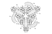
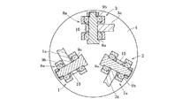
図1および図2は、医療や産業機械などの操作に利用され、スレーブ側リンク機構を有する作業装置とマスター側リンク機構を有する操作装置とを備え、前記操作装置におけるマスター側リンク機構の操作入力により、作業装置におけるスレーブ側リンク機構を動作させるマスタースレーブ方式の遠隔操作システムに適用した実施形態を示す。 FIG. 1 and FIG. 2 are used for operations of medical equipment, industrial machines, and the like, and include an operation device having a slave side link mechanism and an operation device having a master side link mechanism, and an operation input of the master side link mechanism in the operation device. The embodiment applied to the remote operation system of the master slave system which operates the slave side link mechanism in a working device is shown.
この実施形態におけるスレーブ側リンク機構とマスター側リンク機構は、例えば、三次元空間における複雑な加工や物品の取り回し等の作業を高速かつ精密に実行する多関節機械の一部を構成する三組のリンク機構1〜3を具備する。これら三組のリンク機構1〜3のそれぞれは幾何学的に同一形状をなす。このような構造とすることにより、マスター側リンク機構とスレーブ側リンク機構を相似形な構造とすることができる。また、この構造によれば、マスター側リンク機構の操作性を向上させることができ、両リンク機構を広範囲に動作させることが容易となる。 The slave-side link mechanism and the master-side link mechanism in this embodiment are, for example, three sets of parts that constitute part of an articulated machine that performs high-speed and precision operations such as complicated processing and article handling in a three-dimensional space. Link mechanisms 1 to 3 are provided. Each of these three sets of link mechanisms 1 to 3 has the same geometric shape. By adopting such a structure, the master side link mechanism and the slave side link mechanism can have a similar structure. Moreover, according to this structure, the operativity of the master side link mechanism can be improved, and it becomes easy to operate both link mechanisms in a wide range.
図1および図2に示すように、スレーブ側およびマスター側のリンク機構における各リンク機構1〜3は、入力部材4に回動自在に連結された入力側の端部リンク部材1a〜3aと、出力部材5に回動自在に連結された出力側の端部リンク部材1c〜3cと、両端部リンク部材1a〜3a,1c〜3cのそれぞれに回動自在に連結されて両端部リンク部材1a〜3a,1c〜3cを互いに連結する中央リンク部材1b〜3bとで構成され、四つの回転対偶部6a〜8a,6b1,6b2〜8b1,8b2,6c〜8cからなる三節連鎖構造をなす。
As shown in FIGS. 1 and 2, each of the link mechanisms 1 to 3 in the slave-side and master-side link mechanisms includes input side end link members 1 a to 3 a rotatably connected to the
端部リンク部材1a〜3a,1c〜3cは球面リンク構造で、三組のリンク機構1〜3における球面リンク中心は一致しており、また、その中心からの距離も同じである。端部リンク部材1a〜3a,1c〜3cと中央リンク部材1b〜3bとの回転対偶部6b1,6b2〜8b1,8b2の連結軸は、ある交差角をもってもよいし、平行であってもよい。ただし、三組のリンク機構1〜3における中央リンク部材1b〜3bの形状は幾何学的に同一である。
The end link members 1a to 3a and 1c to 3c have a spherical link structure, and the spherical link centers in the three sets of link mechanisms 1 to 3 coincide with each other, and the distances from the centers are also the same. The connecting shafts of the rotating pairs 6b 1 , 6b 2 to 8b 1 , 8b 2 of the end link members 1a to 3a and 1c to 3c and the
リンク機構1〜3において、端部リンク部材1a〜3a,1c〜3cの幾何学的形状が入力側と出力側で等しく、また、中央リンク部材1b〜3bについても入力側と出力側で形状が等しいとき、中央リンク部材1b〜3bの対称面に対して中央リンク部材1b〜3bと入出力部材4,5と連結される端部リンク部材1a〜3a,1c〜3cとの角度位置関係を入力側と出力側で同じにすれば、幾何学的対称性から入力部材4および入力側の端部リンク部材1a〜3aと出力部材5および出力側の端部リンク部材1c〜3cは同じに動き、入力側と出力側は同じ回転角になって等速回転することになる。この等速回転するときの中央リンク部材1b〜3bの対称面を等速二等分面という。
In the link mechanisms 1 to 3, the geometric shapes of the end link members 1a to 3a and 1c to 3c are equal on the input side and the output side, and the shapes of the
このため、入出力部材4,5を共有する同じ幾何学形状のリンク機構1〜3を円周上に複数配置させることにより、複数のリンク機構1〜3が矛盾無く動ける位置として中央リンク部材1b〜3bが等速二等分面上のみの動きに限定され、これにより入力側と出力側は任意の作動角をとっても等速回転が得られる。
For this reason, by arranging a plurality of link mechanisms 1 to 3 having the same geometric shape sharing the input /
この実施形態のリンク機構は、二つ以上の入力側の端部リンク部材1a〜3aの回転対偶部6a〜8aに、サーボモータ等の姿勢制御用アクチュエータを連結し、そのアクチュエータにより、端部リンク部材1a〜3aの回転角位置を制御することで、出力部材5に取り付けられた、例えばツール(図示せず)などの可動部位の姿勢を制御する。
In the link mechanism of this embodiment, an attitude control actuator such as a servo motor is connected to the
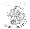
図1に示すリンク機構1〜3の基本的構成は、本出願人が先に提案した特願2003−40086に開示したものと同一であり、入出力部材4,5は、中心軸に貫通孔が形成され、外形を球面状としたドーナツ形状をなすリンクハブである。このリンク機構1〜3の各回転対偶部6a〜8a,6b1,6b2〜8b1,8b2,6c〜8cは、端部リンク部材1a〜3a,1c〜3cを片持ちで支持した構造を具備する。
The basic configuration of the link mechanisms 1 to 3 shown in FIG. 1 is the same as that disclosed in Japanese Patent Application No. 2003-40086 previously proposed by the present applicant, and the input /
一方、図2に示すリンク機構1〜3の基本構成は、本出願人が先に提案した特願2003−388307に開示したものと同一であり、入出力部材4,5は、円盤状をなす。このリンク機構1〜3の各回転対偶部6a〜8a,6b1,6b2〜8b1,8b2,6c〜8cは、端部リンク部材1a〜3a,1c〜3cを両端支持した構造を具備する。
On the other hand, the basic configuration of the link mechanisms 1 to 3 shown in FIG. 2 is the same as that disclosed in the Japanese Patent Application No. 2003-388307 previously proposed by the present applicant, and the input /
図3は、図1に示す片持ち支持のリンク機構における入力部材4と入力側の端部リンク部材1a〜3aの連結部分である回転対偶部6a〜8aを示し、図4は、図2に示す両持ち支持のリンク機構における入力部材4と入力側の端部リンク部材1a〜3aの連結部分である回転対偶部6a〜8aを示す。この回転対偶部6a〜8aは、入力側の端部リンク部材1a〜3aを回転自在に支承する軸10を軸受9a,9bを介して入力部材4に支持した構造を具備する。
FIG. 3 shows rotating
なお、このような軸受構造としたことにより、その連結部分での摩擦抵抗を抑えて回転抵抗の軽減を図ることができ、滑らかな動力伝達を確保できると共に耐久性を向上できる。前述の軸受構造としては、二個のラジアル玉軸受、アンギュラ玉軸受、ローラ軸受、すべり軸受、もしくは一個の複列アンギュラ玉軸受などを使用することが可能である。出力部材5は、図3および図4の入力部材4と同一構造である。軸10の円周方向位置は等間隔でなくてもよいが、入出力部材4,5は同じ円周方向の位置関係とする必要がある。この入出力部材4,5は、三組のリンク機構1〜3で共有され、各軸10に端部リンク部材1a〜3a,1c〜3cが連結される。
By adopting such a bearing structure, it is possible to reduce the rotational resistance by suppressing the frictional resistance at the connecting portion, and to ensure smooth power transmission and improve the durability. As the above-described bearing structure, it is possible to use two radial ball bearings, angular ball bearings, roller bearings, slide bearings, or one double row angular ball bearing. The
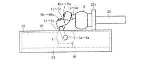
図5は、操作装置におけるマスター側リンク機構を示す。なお、図では、マスター側リンク機構における一つのリンク機構1〜3のみを示している。リンク機構1〜3の入力部材4はスペーサ21を介してベース24上に固定されている。リンク機構1〜3の出力部材5には、操作部材であるスティック25が同軸的に連設されている。従って、ユーザは、マスター側リンク機構のスティック25を把持して動かすことにより、スレーブ側リンク機構を動作させることになる。このマスター側リンク機構の操作時、マスター側リンク機構の出力部材5の姿勢を検知するためには、二つ以上の入力側端部リンク部材1a〜3aの回転角度を検出できるように構成すればよい。
FIG. 5 shows a master side link mechanism in the operating device. In the figure, only one link mechanism 1 to 3 in the master side link mechanism is shown. The
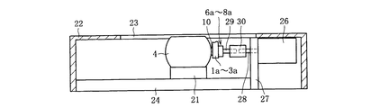
図6は、二つ以上の入力側端部リンク部材1a〜3aの回転角度を検出するための回転角度検出機構26をマスター側リンク機構に付設した一つの設置例を示す。この回転角度検出機構26の設置により、そのマスター側リンク機構の入力側端部リンク部材1a〜3aの回転角度を検知することが可能となり、この回転角度の検知信号はスレーブ側リンク機構の姿勢制御に用いることになる。なお、図ではリンク機構1〜3の入力部材4のみを表記し、他の構成部品を省略している。また、スレーブ側リンク機構に回転角度検出機構を付設する場合も、マスター側リンク機構の設置構造と基本的に同一とすることが可能である。
FIG. 6 shows one installation example in which a rotation
この回転角度検出機構26の設置例では、ベース24に付設された支持フレーム27に回転角度検出機構26を固定している。この回転角度検出機構26の被回転軸28は、入力側端部リンク部材1a〜3aと入力部材4の回転対偶部6a〜8aから延びる回転軸29と同軸になるように配設され、カップリング30を介して回転軸29と連結されている。なお、この回転角度検出機構26としては、インクリメンタル型エンコーダあるいはアブソリュート型エンコーダのいずれであっても使用可能である。また、他の回転角度検出機構としては、二軸方向の傾斜角を検知する二つの傾斜角センサを出力部材5に設置する構造も可能である。
In this installation example of the rotation
回転角度検出機構26を取り付けるための支持フレーム27は、リンク機構1〜3の各構成部品と干渉しないようにリンク機構1〜3から離隔させた位置に設置されている。また、回転角度検出機構26は、ベース24に取り付けられたカバー22によって覆われており、リンク機構1〜3の各構成部品を含む他の部品と当たらないように保護されている。このカバー22は、スティック25の最大径部25c(図5参照)と接触することにより、リンク機構1〜3の折れ角範囲を規制する機能も発揮する。さらに、カバー22の上面には、リンク機構1〜3の動作時に各構成部品と干渉することを回避するために開口部23が形成されている。
The
前述の実施形態では、回転角度検出機構26の被回転軸28と回転対偶部6a〜8aの回転軸29が同軸となるように両者を配置しているが、小型の回転角度検出機構を使用した場合には、その回転角度検出機構を入力部材4の内部に設置することも可能である。また、ギヤ等を介して回転角度検出機構26の回転軸28をシフトするように配置してもよい。このようにすれば、回転角度検出機構26(支持フレーム27)とリンク機構1〜3の各構成部品との干渉を回避することができると共に、マスター側リンク機構を有する操作装置全体のコンパクト化が図れる。
In the above-described embodiment, the
図7は、マスター側リンク機構における入力部材4に回転機構を設置した構造を例示する。つまり、図6に示す入力部材4が固定されたベース24を軸受45を介して基台46に回転可能に設置している。固定された基台46に軸受45の外輪を挿入すると共に、ベース24に軸受45の内輪を挿入してナット47で締め付け固定する。また、この基台46にベース24(入力部材4)の回転角度を検出する回転角度検出機構44を設置している。このようにベース24(入力部材4)の回転角度を回転角度検出機構44により検出することができる。
FIG. 7 illustrates a structure in which a rotation mechanism is installed on the
なお、この例では、入力部材側のベース24に回転自由度を付与しているが、出力部材側で回転自由度を付与する構造も可能である。 In this example, the degree of freedom of rotation is given to the base 24 on the input member side, but a structure in which the degree of freedom of rotation is given on the output member side is also possible.
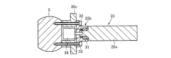
図8は、マスター側リンク機構において、リンク機構1〜3の出力部材5の先端にスティック25を回転可能に設置した構造を例示する。二自由度のリンク機構の場合、姿勢に応じて出力部材5の表面角度が決まってしまうため、このようにマスター側リンク機構の出力部材5にスティック25を回転可能に設置すれば、マスター側リンク機構の操作入力に際して、ユーザの操作性が大幅に向上する。
FIG. 8 illustrates a structure in which a
このスティック回転構造としては、スティック25を把持部25a、軸受部25bおよび最大径部25cに分離し、その軸受部25bに軸受31の外輪を挿入して加締め等により固定すると共に、把持部25aの先端を軸受31の内輪に挿入してナット32で締め付け固定する。そして、軸受部25bを最大径部25cと共に出力部材5にボルト33により共締めする。このような構造としたことにより、出力部材5に対してスティック25の把持部25aが回転可能となる。
In this stick rotating structure, the
図9は、前述のスティック25の最大径部25cに把持部25aの回転角度を検出する回転角度検出機構34を設置した構造を例示する。このようにスティック25の把持部25aの回転角度を回転角度検出機構34により検出することができる。
FIG. 9 illustrates a structure in which a rotation
図7〜図9の実施形態のように入力部材側あるいは出力部材側に回転自由度を付与した構造とすれば、三自由度のマスター側リンク機構を操作することによりスレーブ側リンク機構を三自由度で動作させることができる。なお、これら実施形態では、回転自由度を付与しているが、この回転自由度の代わりに入力部材側あるいは出力部材側に直動機構を設け、その直進移動量を検出するセンサ機構を設けることも可能である。このように直動機構およびそのセンサ機構を設ければ、直進自由度を付与した三自由度のマスター側リンク機構を操作することによりスレーブ側リンク機構を、直進自由度を含む三自由度で動作させることができる。 7 to 9, if the input member side or the output member side is provided with a rotational degree of freedom, the slave side link mechanism can be made free by operating the master side link mechanism having three degrees of freedom. Can be operated in degrees. In these embodiments, a degree of freedom of rotation is given, but instead of this degree of freedom of rotation, a linear motion mechanism is provided on the input member side or output member side, and a sensor mechanism that detects the amount of linear movement is provided. Is also possible. If the linear motion mechanism and its sensor mechanism are provided in this way, the slave side link mechanism can be operated with three degrees of freedom including the straight degree of freedom by operating the master side link mechanism with three degrees of freedom. Can be made.
また、前述の回転機構と直動機構の両方を設置すると共にそれらのセンサ機構を設けることにより、四自由度のマスター側リンク機構を操作することによりスレーブ側リンク機構を四自由度で動作させることも可能である。なお、四自由度機構の場合、直動機構の上部に回転機構を設ければよい。このようにリンク機構1〜3の出力側に自由度機構を追加する構造の場合、リンク機構1〜3の内部空間S(図1および図2参照)に配線を挿通させて引き回すようにすれば、リンク機構1〜3をどれだけ旋回させても配線の捩れ問題が発生することはない。 In addition, by installing both the rotation mechanism and the linear motion mechanism described above and providing their sensor mechanisms, the slave side link mechanism can be operated with four degrees of freedom by operating the master side link mechanism with four degrees of freedom. Is also possible. In the case of a four-degree-of-freedom mechanism, a rotation mechanism may be provided above the linear motion mechanism. In the case of the structure in which the degree of freedom mechanism is added to the output side of the link mechanisms 1 to 3 as described above, if the wiring is inserted through the internal space S of the link mechanisms 1 to 3 (see FIGS. 1 and 2) No matter how much the link mechanisms 1 to 3 are turned, the problem of twisting of the wiring does not occur.
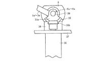
図10は、作業装置におけるスレーブ側リンク機構の一部を示す。このスレーブ側リンク機構は、入力側端部リンク部材1a〜3aと入力部材4の回転対偶部6a〜8aから延びる回転軸39に回転伝達部35を設置し、その回転伝達部35を介してサーボモータ等の姿勢制御用アクチュエータ36を回転軸39に連結した構造を具備する。この回転軸39は、入力側端部リンク部材1a〜3aに対して止めねじ等で回り止めされている。この姿勢制御用アクチュエータ36により回転伝達部35を介して回転対偶部6a〜8aの回転軸39を回転させることによってスレーブ側リンク機構の姿勢を制御する。
FIG. 10 shows a part of the slave side link mechanism in the working device. In the slave side link mechanism, a
なお、このアクチュエータ36は、ベース37に取り付けて二つ以上のリンク機構1〜3に設置されている。また、そのベース37にはスペーサ38を介して入力部材4が固定されている。このスペーサ38は、リンク機構1〜3が最大折れ角をとった状態などでそのリンク機構1〜3の各構成部品がベース37と干渉することを回避すると共に、歯車35aと傘歯車35bからなる回転伝達部35を設置するスペースを確保するためのものである。
The
前述の回転伝達部35は、その回転伝達部35の動作範囲を規制するような形状を有する部品、例えば釣鐘形の歯車35aを回転軸39に同軸的に装着し、その歯車35aと噛合する傘歯車35bを姿勢制御用アクチュエータ36の出力軸に同軸に取り付けた構造としている。なお、この回転伝達部35は、傘歯車などを利用する以外に、他の歯車機構やベルト等で構成することも可能である。
The above-mentioned
図11は、図10の入力側端部リンク部材1a〜3aの回転角度を検出するための回転角度検出機構40をスレーブ側リンク機構に付設した一つの設置例を示す。この回転角度検出機構40の設置により、そのスレーブ側リンク機構の入力側端部リンク部材1a〜3aの回転角度を検知することが可能となり、この回転角度の検知信号はスレーブ側リンク機構の姿勢制御に用いることになる。
FIG. 11 shows one installation example in which a rotation
この回転角度検出機構40の設置例では、ベース37に付設された支持フレーム41に回転角度検出機構40を固定している。この回転角度検出機構40の被回転軸42は、入力側端部リンク部材1a〜3aと入力部材4の回転対偶部6a〜8aから延びる回転軸39と同軸になるように配設され、カップリング43を介して回転軸39と連結されている。
In this installation example of the rotation
なお、この回転角度検出機構41としては、マスター側リンク機構の場合(図6参照)と同様、インクリメンタル型エンコーダあるいはアブソリュート型エンコーダのいずれであっても使用可能である。また、他の回転角度検出機構としては、二軸方向の傾斜角を検知する二つの傾斜角センサを出力部材5に設置する構造も可能である。さらに、回転角度検出機構40を取り付けるための支持フレーム41は、リンク機構1〜3の各構成部品と干渉しないようにリンク機構1〜3から離隔させた位置に設置されている。
As the rotation
このスレーブ側リンク機構においても、前述のマスター側リンク機構と同様、リンク機構1〜3の出力部材5に回転機構や直動機構を設置すると共にそれら回転機構や直動機構のセンサ機構を設けることにより、三自由度機構や四自由度機構が可能である。但し、このスレーブ側リンク機構の自由度とマスター側リンク機構の自由度は一致している必要がある。
Also in this slave side link mechanism, similarly to the master side link mechanism described above, a rotation mechanism and a linear motion mechanism are installed on the
以上の構成からなるマスター側リンク機構を有する操作装置とスレーブ側リンク機構を有する作業装置とで構成された遠隔操作システムの制御について、以下に説明する。この遠隔操作システムの制御方法は、前述した回転角度検出機構26,40(図6および図11参照)の分解能やリンク機構1〜3の中央リンク部材1b〜3bの軸角γによって異なる。
The control of the remote operation system composed of the operation device having the master side link mechanism having the above configuration and the work device having the slave side link mechanism will be described below. The control method of the remote operation system differs depending on the resolution of the rotation
なお、各リンク機構1〜3は、円周方向に沿って等間隔に配置されている必要がある。また、以下では、回転角度検出機構26,40として、インクリメンタル型エンコーダを使用する場合について説明するが、ポテンショメータのような回転角度検出機構を用いる場合には、回転角度検出機構から得られた出力信号をAD変換する必要がある。
In addition, each link mechanism 1-3 needs to be arrange | positioned at equal intervals along the circumferential direction. In the following, the case where an incremental encoder is used as the rotation
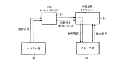
図12は、マスター側リンク機構を有する操作装置51とスレーブ側リンク機構を有する作業装置52において、リンク機構1〜3の軸角γが同一で、かつ、回転角度検出機構26,40等、つまり、インクリメンタル型エンコーダの分解能が異なる場合の制御方法を説明するためのブロック図である。なお、図中で示す二本の線は、マスター側リンク機構とスレーブ側リンク機構のそれぞれに設置された二つのエンコーダから出力される検知信号を意味する。
FIG. 12 shows that in the operating
マスター側リンク機構とスレーブ側リンク機構は同一構造でその軸角γが同一であるため、両リンク機構の原点位置を予め揃えておけば、マスター側のエンコーダから出力される検知信号から求められる偏差信号に、マスター側のエンコーダの分解能に対するスレーブ側のエンコーダの分解能の比率をかければ、スレーブ側リンク機構の指令パルスとすることができる。 Since the master side link mechanism and the slave side link mechanism have the same structure and the same shaft angle γ, if the origin positions of both link mechanisms are aligned in advance, the deviation obtained from the detection signal output from the master side encoder If the ratio of the resolution of the slave side encoder to the resolution of the master side encoder is applied to the signal, the command pulse of the slave side link mechanism can be obtained.
つまり、マスター側リンク機構におけるエンコーダの検知信号をPC53(パルスボード)に取り込み、前回のカウンタ値と現在のカウンタ値を比較することにより偏差信号を求め、この偏差信号に、マスター側リンク機構におけるエンコーダの分解能に対するスレーブ側リンク機構におけるエンコーダの分解能の比率をかけて定数倍すれば、スレーブ側リンク機構の出力部材5の現在位置とマスター側リンク機構の出力部材5の現在位置を比較しなくても、スレーブ側リンク機構の指令パルスとすることができる。
That is, a detection signal of the encoder in the master side link mechanism is taken into the PC 53 (pulse board), a deviation signal is obtained by comparing the previous counter value with the current counter value, and the deviation signal is obtained from the encoder in the master side link mechanism. If the ratio of the resolution of the encoder in the slave side link mechanism to the resolution of the slave side is multiplied by a constant, the current position of the
その指令パルスを制御基板54(ドライバ)に送信すれば、それがスレーブ側リンク機構を姿勢制御するためのアクチュエータへの制御電流となり、マスター側リンク機構と同じ動作をスレーブ側リンク機構でも実行させることができる。但し、エンコーダの分解能の変換機能を持つ制御基板54(ドライバ)では、後述するようにマスター側リンク機構におけるエンコーダの検知信号を制御基板54(ドライバ)に直接的に送信してもよい(図14参照)。但し、スレーブ側リンク機構におけるエンコーダの検知信号をPC53(パルスボード)に読み込み、制御が確実に実行されているか否かを確認し、フィードバック制御を実行してもよい。 If the command pulse is transmitted to the control board 54 (driver), it becomes a control current to the actuator for attitude control of the slave side link mechanism, and the same operation as the master side link mechanism is also executed in the slave side link mechanism. Can do. However, the control board 54 (driver) having the encoder resolution conversion function may directly transmit the encoder detection signal in the master side link mechanism to the control board 54 (driver) as described later (FIG. 14). reference). However, the encoder detection signal in the slave side link mechanism may be read into the PC 53 (pulse board) to check whether the control is being executed reliably, and the feedback control may be executed.
図13は、マスター側リンク機構を有する操作装置51とスレーブ側リンク機構を有する作業装置52において、リンク機構1〜3の軸角γが異なり、かつ、エンコーダの分解能も異なる場合の制御方法を説明するためのブロック図である。
FIG. 13 illustrates a control method when the operating
ここで、図15および図16に示すように折れ角θと旋回角φで規定される出力部材5の姿勢と入力側の端部リンク部材1a〜3aの回転角βnとの関係式(γは中央リンク部材1b〜3bの軸角、δは基準となる端部リンク部材に対する各端部リンク部材の円周方向離間角)、
cos(θ/2)sinβn−sin(θ/2)sin(φ+δn)cosβn+sin(γ/2)=0
となる。つまり、出力部材5の姿勢は、二自由度(折れ角θと旋回角φ)で規定することができ、出力部材5の姿勢(折れ角θと旋回角φ)と入力側の端部リンク部材1a〜3aの回転角βnとの関係を以下の式で規定することができる。
Here, as shown in FIGS. 15 and 16, a relational expression (γ is a relation between the attitude of the
cos (θ / 2) sinβn−sin (θ / 2) sin (φ + δn) cosβn + sin (γ / 2) = 0
It becomes. That is, the attitude of the
なお、下記の関係式におけるパラメータθは、入力部材4に対して出力部材5が垂直方向に傾斜した角度、パラメータφは、入力部材4に対して出力部材5が0°から水平方向に傾斜した角度、パラメータβ1,β2(リンク機構1〜3が三組であるため、そのうちの二つのパラメータで規定可能である)は、入力側の端部リンク部材1a〜3aの回転対偶部6a〜8aにおける回転角、パラメータγは、入力側の端部リンク部材1a〜3aに連結された中央リンク部材1b〜3bの回転対偶部6b1〜8b1と、出力側の端部リンク部材1c〜3cに連結された中央リンク部材1b〜3bの回転対偶部6b2〜8b2とがなす角度である。この関係式は、リンク機構1〜3が三組で、端部リンク部材1a〜3a,1c〜3cの円周方向位置が等間隔の場合である。
cos(θ/2)sinβ1−sin(θ/2)sinφcosβ1+sin(γ/2)=0
cos(θ/2)sinβ2−sin(θ/2)sin(φ+120°)cosβ2+sin(γ/2)=0
cos(θ/2)sinβ3−sin(θ/2)sin(φ+240°)cosβ3+sin(γ/2)=0
The parameter θ in the following relational expression is the angle at which the
cos (θ / 2) sinβ 1 −sin (θ / 2) sinφcosβ 1 + sin (γ / 2) = 0
cos (θ / 2) sinβ 2 −sin (θ / 2) sin (φ + 120 °) cosβ 2 + sin (γ / 2) = 0
cos (θ / 2) sinβ 3 −sin (θ / 2) sin (φ + 240 °) cosβ 3 + sin (γ / 2) = 0
これら二つ以上の方程式を解くことにより、前述の関係式の逆変換でもって出力部材5の姿勢を制御することができる。つまり、出力部材5の姿勢制御は、所定の姿勢を規定する目標値を関係式に入力することにより、その姿勢入力に対する入力側の端部リンク部材1a〜3aの回転角を求めることで実現できる。
By solving these two or more equations, the attitude of the
そのため、マスター側リンク機構とスレーブ側リンク機構で中央リンク部材1b〜3bの軸角γが異なると、マスター側リンク機構とスレーブ側リンク機構が同じ姿勢(折れ角θと旋回角φ)でも、その時の入力側端部リンク部材1a〜3aの回転角度βnは、マスター側リンク機構とスレーブ側リンク機構で異なる。つまり、図12に示すようにマスター側リンク機構におけるエンコーダの検知信号をPC53(パルスボード)に取り込み、単に偏差信号に、マスター側リンク機構におけるエンコーダの分解能に対するスレーブ側リンク機構におけるエンコーダの分解能の比率をかけてスレーブ側リンク機構の指令パルスとすることができない。
Therefore, if the axial angle γ of the
そこで、図13に示すようにマスター側リンク機構におけるエンコーダから得られる二つの検知信号をPC53(パルスボード)に取り込み、前述の関係式による順変換でもってマスター側リンク機構の出力部材5の姿勢(折れ角θと旋回角φ)を求める。
Therefore, as shown in FIG. 13, the two detection signals obtained from the encoder in the master side link mechanism are taken into the PC 53 (pulse board), and the posture of the
スレーブ側リンク機構における出力部材5の姿勢(折れ角θと旋回角φ)がマスター側リンク機構における出力部材5の姿勢(折れ角θと旋回角φ)になるようにスレーブ側リンク機構における二つの入力側端部リンク部材1a〜3aの回転角度β1,β2を前述の関係式による逆変換を用いて求め、スレーブ側リンク機構における現在位置との偏差分を指令パルスとして制御基板54(ドライバ)に送信し、スレーブ側リンク機構におけるアクチュエータの制御電流とする。この時、マスター側リンク機構とスレーブ側リンク機構は、エンコーダの分解能が異なるため、マスター側リンク機構とスレーブ側リンク機構で同じ回転角度β1,β2を動かす場合でも指令パルス数は異なる。
Two positions in the slave side link mechanism are set so that the posture (fold angle θ and turning angle φ) of the
図14は、マスター側リンク機構を有する操作装置51とスレーブ側リンク機構を有する作業装置52において、リンク機構1〜3の軸角γが同一で、かつ、エンコーダの分解能も同一となる場合の制御方法を説明するためのブロック図である。
FIG. 14 shows the control in the case where the shaft angle γ of the link mechanisms 1 to 3 is the same and the resolution of the encoder is the same in the operating
リンク機構1〜3の軸角γが同一で、かつ、エンコーダの分解能も同一であるため、マスター側リンク機構におけるエンコーダの検知信号がそのままスレーブ側リンク機構への指令パルスとなる。前述した図12および図13に示す例では、マスター側リンク機構におけるエンコーダの検知信号がスレーブ側リンク機構の指令パルスと異なるため、PC53(パルスボード)を介してマスター側リンク機構におけるエンコーダの検知信号をスレーブ側リンク機構の指令パルスに変換していたが、図14に示す例では、マスター側リンク機構におけるエンコーダの検知信号をそのままスレーブ側リンク機構への指令パルスとして制御基板54(ドライバ)に送信することができる。そのため、遠隔操作システムの簡易化が図れる。 Since the shaft mechanisms γ of the link mechanisms 1 to 3 are the same and the resolution of the encoder is also the same, the detection signal of the encoder in the master side link mechanism becomes the command pulse to the slave side link mechanism as it is. In the example shown in FIGS. 12 and 13, the encoder detection signal in the master side link mechanism is different from the command pulse in the slave side link mechanism, so the encoder detection signal in the master side link mechanism via the PC 53 (pulse board). 14 is converted into a command pulse for the slave side link mechanism. In the example shown in FIG. 14, the detection signal of the encoder in the master side link mechanism is directly transmitted to the control board 54 (driver) as a command pulse for the slave side link mechanism. can do. Therefore, the remote operation system can be simplified.
但し、スレーブ側リンク機構におけるエンコーダの検知信号をPC53(パルスボード)に読み込み、制御が確実に実行されているか否かを確認し、フィードバック制御を実行してもよい。一般に、スレーブ側リンク機構におけるアクチュエータには減速機構とサーボモータを用い、そのサーボモータのエンコーダで姿勢制御を実行している。より大きなトルクを出すために減速比を大きくとることが好ましく、エンコーダは減速機の下側に取り付けられているため、スレーブ側リンク機構におけるエンコーダの分解能はマスター側リンク機構におけるエンコーダと比較すると大きくなる。 However, the encoder detection signal in the slave side link mechanism may be read into the PC 53 (pulse board) to check whether the control is being executed reliably, and the feedback control may be executed. Generally, a deceleration mechanism and a servo motor are used as actuators in the slave side link mechanism, and attitude control is executed by an encoder of the servo motor. It is preferable to increase the reduction ratio in order to produce a larger torque, and the encoder is attached to the lower side of the reduction gear. Therefore, the resolution of the encoder in the slave side link mechanism is larger than that of the encoder in the master side link mechanism. .
しかしながら、図11に示すようにスレーブ側リンク機構において、入力側端部リンク部材1a〜3aの回転角度を検出する回転角度検出機構40を回転対偶部6a〜8aの回転軸39と同軸配置し、その回転角度検出機構40の分解能をマスター側リンク機構における回転角度検出機構26と同一にし、その回転角度検出機構40によりアクチュエータを制御すれば、図14で説明したような制御方法が可能である。
However, as shown in FIG. 11, in the slave side link mechanism, the rotation
また、二自由度機構のマスター側リンク機構とスレーブ側リンク機構に回転機構や直動機構を付設して、三自由度機構や四自由度機構とした場合には、マスター側リンク機構とスレーブ側リンク機構の回転機構や直動機構は、そのセンサ機構の分解能が同一もしくは定数倍となるため、前述した図12や図13で説明した制御方法を採用すればよい。 In addition, when a rotation mechanism or linear motion mechanism is added to the master side link mechanism and slave side link mechanism of the two degree of freedom mechanism to form a three degree of freedom mechanism or a four degree of freedom mechanism, the master side link mechanism and slave side Since the rotation mechanism and the linear motion mechanism of the link mechanism have the same resolution or a multiple of the sensor mechanism, the control method described with reference to FIGS.
1〜3 リンク機構
1a〜3a,1c〜3c 端部リンク部材
1b〜3b 中央リンク部材
4 入力部材
5 出力部材
6a〜8a 回転対偶部
6b1,6b2〜8b1,8b2 回転対偶部
6c〜8c 回転対偶部
25 操作部材(スティック)
26,40 回転角度検出機構
36 姿勢制御用アクチュエータ
1-3 linkage 1a~3a, 1c~3c
26, 40 Rotation
Claims (8)
前記作業装置または操作装置の少なくともいずれか一方は、入出力側にそれぞれ配された入出力部材に対して回転可能に端部リンク部材を連結し、入力側と出力側のそれぞれの端部リンク部材を中央リンク部材に対して回転可能に連結した四つの回転対偶部からなるリンク機構を三組以上有し、各リンク機構の中央部における横断面に関して入力側と出力側を幾何学的に同一としたことを特徴とする遠隔操作システム。 A remote operation system comprising a work device having a slave side link mechanism and an operation device having a master side link mechanism, and driving the slave side link mechanism in the work device by an operation input of the master side link mechanism in the operation device. ,
At least one of the work device and the operation device is connected to an input / output member disposed on the input / output side so that the end link member is rotatable, and the input side and output side end link members are respectively connected. There are three or more sets of link mechanisms consisting of four rotating pairs that are rotatably connected to the central link member, and the input side and the output side are geometrically identical with respect to the cross section at the center of each link mechanism. A remote control system characterized by that.
cos(θ/2)sinβn−sin(θ/2)sin(φ+δn)cosβn+sin(γ/2)=0
による順変換でもって算出し、それに基づいてマスター側とスレーブ側のリンク機構における出力部材の姿勢が同一となるように前記関係式の逆変換でもってスレーブ側リンク機構の姿勢を制御可能とした請求項1〜5のいずれか一項に記載の遠隔操作システム。 The posture of the output member in the master side link mechanism is a relational expression between the posture of the output member defined by the bending angle θ and the turning angle φ and the rotation angle βn of the end link member on the input side (γ is the central link member Axial angle, δ is the circumferential separation angle of each end link member with respect to the reference end link member),
cos (θ / 2) sinβn−sin (θ / 2) sin (φ + δn) cosβn + sin (γ / 2) = 0
Based on this, the posture of the slave side link mechanism can be controlled by the inverse transformation of the relational expression so that the postures of the output members in the master side and slave side link mechanisms are the same. Item 6. The remote control system according to any one of Items 1 to 5.
Priority Applications (1)
| Application Number | Priority Date | Filing Date | Title |
|---|---|---|---|
| JP2004124678A JP2005305585A (en) | 2004-04-20 | 2004-04-20 | Remote control system |
Applications Claiming Priority (1)
| Application Number | Priority Date | Filing Date | Title |
|---|---|---|---|
| JP2004124678A JP2005305585A (en) | 2004-04-20 | 2004-04-20 | Remote control system |
Publications (1)
| Publication Number | Publication Date |
|---|---|
| JP2005305585A true JP2005305585A (en) | 2005-11-04 |
Family
ID=35434928
Family Applications (1)
| Application Number | Title | Priority Date | Filing Date |
|---|---|---|---|
| JP2004124678A Withdrawn JP2005305585A (en) | 2004-04-20 | 2004-04-20 | Remote control system |
Country Status (1)
| Country | Link |
|---|---|
| JP (1) | JP2005305585A (en) |
Cited By (12)
| Publication number | Priority date | Publication date | Assignee | Title |
|---|---|---|---|---|
| WO2010128638A1 (en) * | 2009-05-08 | 2010-11-11 | Ntn株式会社 | Remote-controlled work robot |
| WO2011145499A1 (en) * | 2010-05-19 | 2011-11-24 | Ntn株式会社 | Link actuation device |
| WO2011148892A1 (en) * | 2010-05-28 | 2011-12-01 | Ntn株式会社 | Remote operation type actuator |
| WO2012043324A1 (en) * | 2010-09-30 | 2012-04-05 | Ntn株式会社 | Remotely operated actuator |
| WO2012049996A1 (en) * | 2010-10-14 | 2012-04-19 | Ntn株式会社 | Link actuating device |
| WO2013042577A1 (en) * | 2011-09-22 | 2013-03-28 | Ntn株式会社 | Link actuating device |
| WO2013065560A1 (en) * | 2011-11-02 | 2013-05-10 | Ntn株式会社 | Method for initially setting position of origin of link actuators, and link actuator |
| WO2013069533A1 (en) * | 2011-11-07 | 2013-05-16 | Ntn株式会社 | Link operation device |
| JP2015055262A (en) * | 2013-09-10 | 2015-03-23 | Ntn株式会社 | Link operation device |
| CN105269557A (en) * | 2012-03-23 | 2016-01-27 | Ntn株式会社 | Link actuation device |
| US11083533B2 (en) | 2016-02-25 | 2021-08-10 | Olympus Corporation | Manipulator system and operating method thereof |
| US11298199B2 (en) | 2016-02-25 | 2022-04-12 | Olympus Corporation | Manipulator system and method for restricting a retreating motion of a manipulator according to a protrusion state of a manipulator joint |
-
2004
- 2004-04-20 JP JP2004124678A patent/JP2005305585A/en not_active Withdrawn
Cited By (29)
| Publication number | Priority date | Publication date | Assignee | Title |
|---|---|---|---|---|
| WO2010128638A1 (en) * | 2009-05-08 | 2010-11-11 | Ntn株式会社 | Remote-controlled work robot |
| US8316961B2 (en) | 2009-05-08 | 2012-11-27 | Ntn Corporation | Remote-controlled work robot |
| US9073204B2 (en) | 2010-05-19 | 2015-07-07 | Ntn Corporation | Link actuation device |
| WO2011145499A1 (en) * | 2010-05-19 | 2011-11-24 | Ntn株式会社 | Link actuation device |
| JP2011240440A (en) * | 2010-05-19 | 2011-12-01 | Ntn Corp | Link actuation device |
| DE112011101684B4 (en) | 2010-05-19 | 2020-06-18 | Ntn Corp. | Link actuator |
| CN102892559A (en) * | 2010-05-19 | 2013-01-23 | Ntn株式会社 | Link actuation device |
| WO2011148892A1 (en) * | 2010-05-28 | 2011-12-01 | Ntn株式会社 | Remote operation type actuator |
| WO2012043324A1 (en) * | 2010-09-30 | 2012-04-05 | Ntn株式会社 | Remotely operated actuator |
| JP2012075498A (en) * | 2010-09-30 | 2012-04-19 | Ntn Corp | Remotely operated actuator |
| US9126339B2 (en) | 2010-09-30 | 2015-09-08 | Ntn Corporation | Remote controlled actuator assembly |
| US9249869B2 (en) | 2010-10-14 | 2016-02-02 | Ntn Corporation | Link actuating device |
| WO2012049996A1 (en) * | 2010-10-14 | 2012-04-19 | Ntn株式会社 | Link actuating device |
| JP2012082937A (en) * | 2010-10-14 | 2012-04-26 | Ntn Corp | Link actuating device |
| CN103827547A (en) * | 2011-09-22 | 2014-05-28 | Ntn株式会社 | Link actuating device |
| JP2013068280A (en) * | 2011-09-22 | 2013-04-18 | Ntn Corp | Link actuating device |
| WO2013042577A1 (en) * | 2011-09-22 | 2013-03-28 | Ntn株式会社 | Link actuating device |
| US9243696B2 (en) | 2011-09-22 | 2016-01-26 | Ntn Corporation | Link actuating device |
| US10661398B2 (en) | 2011-11-02 | 2020-05-26 | Ntn Corporation | Link actuator to initially set position of origin |
| JP2013096525A (en) * | 2011-11-02 | 2013-05-20 | Ntn Corp | Method for initially setting position of origin of link actuation device, and link actuation device |
| WO2013065560A1 (en) * | 2011-11-02 | 2013-05-10 | Ntn株式会社 | Method for initially setting position of origin of link actuators, and link actuator |
| EP2775168A4 (en) * | 2011-11-02 | 2016-07-06 | Ntn Toyo Bearing Co Ltd | Method for initially setting position of origin of link actuators, and link actuator |
| US10022827B2 (en) | 2011-11-02 | 2018-07-17 | Ntn Corporation | Method for initially setting position of origin of link actuators, and link actuator |
| WO2013069533A1 (en) * | 2011-11-07 | 2013-05-16 | Ntn株式会社 | Link operation device |
| US9394979B2 (en) | 2011-11-07 | 2016-07-19 | Ntn Corporation | Link actuating device |
| CN105269557A (en) * | 2012-03-23 | 2016-01-27 | Ntn株式会社 | Link actuation device |
| JP2015055262A (en) * | 2013-09-10 | 2015-03-23 | Ntn株式会社 | Link operation device |
| US11083533B2 (en) | 2016-02-25 | 2021-08-10 | Olympus Corporation | Manipulator system and operating method thereof |
| US11298199B2 (en) | 2016-02-25 | 2022-04-12 | Olympus Corporation | Manipulator system and method for restricting a retreating motion of a manipulator according to a protrusion state of a manipulator joint |
Similar Documents
| Publication | Publication Date | Title |
|---|---|---|
| US5271290A (en) | Actuator assembly | |
| EP1684950B1 (en) | Parallel kinematics mechanism with a concentric spherical joint | |
| KR100299210B1 (en) | Master device having force reflective function | |
| KR101457147B1 (en) | Humanoid robot and shoulder joint assembly thereof | |
| US5673595A (en) | Four degree-of-freedom manipulator | |
| JP2005144627A (en) | Link operating device | |
| JP6502115B2 (en) | Articulated Robot with Link Actuator | |
| CN111601685B (en) | Industrial robot arm | |
| JP2005305585A (en) | Remote control system | |
| US20100206120A1 (en) | Parallel robot provided with wrist section having three degrees of freedom | |
| JP2001293676A (en) | Parallel link robot | |
| JPH03202288A (en) | Industrial robot | |
| GB2115778A (en) | Mechanical actuators | |
| US20110290061A1 (en) | Hybrid serial-parallel linkage based six degrees of freedom robotic manipulator | |
| JP2021049636A (en) | Multi-axis gripper for lab automation robot | |
| JP2519289B2 (en) | Wrist mechanism of robot manipulator | |
| JP2005299828A (en) | Link operating device | |
| US20040013509A1 (en) | Parallel kinematics mechanism with a concentric spherical joint | |
| JP2019198960A (en) | Articulated robot using link operation device | |
| WO2019103068A1 (en) | Operation device | |
| JP2005226777A (en) | Link operating device | |
| JP2005127475A (en) | Link operating device | |
| JPH09290382A (en) | Manipulator capable of making six-freedom degree motion suited for reaction force feedback | |
| JP2014117783A (en) | Hand guide system for robot, and hand guide device | |
| JPH07214482A (en) | Articulated arm mechanism |
Legal Events
| Date | Code | Title | Description |
|---|---|---|---|
| A300 | Withdrawal of application because of no request for examination |
Free format text: JAPANESE INTERMEDIATE CODE: A300 Effective date: 20070703 |