JP2005299828A - Link operating device - Google Patents
Link operating device Download PDFInfo
- Publication number
- JP2005299828A JP2005299828A JP2004118270A JP2004118270A JP2005299828A JP 2005299828 A JP2005299828 A JP 2005299828A JP 2004118270 A JP2004118270 A JP 2004118270A JP 2004118270 A JP2004118270 A JP 2004118270A JP 2005299828 A JP2005299828 A JP 2005299828A
- Authority
- JP
- Japan
- Prior art keywords
- link
- input
- output
- end link
- input side
- Prior art date
- Legal status (The legal status is an assumption and is not a legal conclusion. Google has not performed a legal analysis and makes no representation as to the accuracy of the status listed.)
- Withdrawn
Links
Images


Landscapes
- Manipulator (AREA)
- Transmission Devices (AREA)
Abstract
Description
本発明は、リンク作動装置に関し、例えば、三次元空間における複雑な加工や物品の取り回し等の作業を高速かつ精密に実行するロボット関節などのリンク機構に利用されるリンク作動装置に関する。 The present invention relates to a link operating device, and for example, relates to a link operating device used for a link mechanism such as a robot joint that performs complicated processing and article handling in a three-dimensional space at high speed and with precision.
例えば、三次元空間における複雑な加工や物品の取り回し等の作業を高速かつ精密に実行するリンク作動装置として、パラレルリンク機構を具備した作業装置がある(例えば、特許文献1参照)。 For example, there is a working device equipped with a parallel link mechanism as a link actuating device that performs high-speed and precise operations such as complicated processing and article handling in a three-dimensional space (see, for example, Patent Document 1).
この作業装置は、ベースプレートとトラベリングプレートとの間を接続する複数のリンクを協調させて伸縮させることでベースプレートに対するトラベリングプレートの位置および姿勢を変化させるパラレルリンク機構を具備する。このパラレルリンク機構のトラベリングプレートにツールを取り付け、ワークを保持するテーブルを回転可能に配設することにより、テーブル上のワークに対するツールの位置および姿勢を自由に変えられるようにして、ツールによる三次元空間内での複雑な加工や物品の取り回しを可能にしている。 This working apparatus includes a parallel link mechanism that changes the position and posture of the traveling plate with respect to the base plate by cooperatively expanding and contracting a plurality of links connecting the base plate and the traveling plate. By attaching a tool to the traveling plate of this parallel link mechanism and rotatably arranging a table to hold the workpiece, the position and posture of the tool with respect to the workpiece on the table can be freely changed. It enables complex processing and handling of articles in the space.
前記パラレルリンク機構では、可動部分の質量を軽減することができ、また、各リンクの位置決め誤差がその先端部で平均化されるなど、三次元空間における複雑な加工や物品の取り回し等の作業を高速かつ精密に実行する上で大きな特徴を具備している。
しかしながら、前述したパラレルリンク機構では、各リンクの作動角が小さいため、トラベリングプレートの作動範囲を大きく設定しようとすると、リンク長が長くなることにより、機構全体の寸法が大きくなって装置の大型化を招来するという問題があった。また、機構全体の剛性が低く、トラベリングプレートに搭載されるツールの重量、つまり、トラベリングプレートにおける可搬重量も小さいものに制限されるという問題もあった。 However, in the parallel link mechanism described above, since the operating angle of each link is small, if the operating range of the traveling plate is set to be large, the link length becomes long, which increases the overall size of the mechanism and increases the size of the device. There was a problem of inviting. There is also a problem that the rigidity of the entire mechanism is low and the weight of the tool mounted on the traveling plate, that is, the loadable weight of the traveling plate is limited to a small one.
この問題点を解消するため、本出願人は、コンパクトな構成で、剛性が高く、しかも可搬重量が大きいリンク機構を具備したリンク作動装置を先に提案している(特願2003−40086)。 In order to solve this problem, the present applicant has previously proposed a link actuating device having a link mechanism having a compact structure, high rigidity, and a large transportable weight (Japanese Patent Application No. 2003-40086). .
このリンク作動装置は、入力部材と出力部材のそれぞれに設けたリンクハブに対して回転可能に端部リンク部材を連結し、入力側と出力側のそれぞれの端部リンク部材を中央リンク部材に対して回転可能に連結したリンク機構を三組以上有し、各リンク機構の中央部における横断面に関して入力側と出力側を幾何学的に同一とした構成を具備するものである。各リンク機構は、四つの回転対偶部からなる三節連鎖を構成している。 In this link actuating device, the end link members are rotatably connected to the link hubs provided on the input member and the output member, and the end link members on the input side and the output side are connected to the central link member. And three or more sets of link mechanisms that are rotatably connected to each other, and a configuration in which the input side and the output side are geometrically identical with respect to the cross section at the center of each link mechanism. Each link mechanism constitutes a three-bar chain composed of four rotating pairs.
このリンク作動装置では、リンクハブに軸受外輪を内包すると共に軸受内輪を端部リンク部材と結合させることにより、リンクハブ内に軸受構造を埋設したものであり、リンク機構の内部空間に回転伝達部を配設し、その回転伝達部を介して端部リンク部材の姿勢を制御するアクチュエータを設けたものであり、入力側リンクハブを固定し、回転伝達部を駆動することにより出力側リンクハブを二自由度で動作させるようにしたものである。 In this link actuating device, the bearing outer ring is included in the link hub and the bearing inner ring is coupled to the end link member so that the bearing structure is embedded in the link hub. And an actuator for controlling the posture of the end link member via the rotation transmission portion. The input side link hub is fixed and the rotation transmission portion is driven to fix the output side link hub. It is designed to operate with two degrees of freedom.
このリンク作動装置では、リンク機構をアクチュエータで姿勢制御する場合、リンク機構の各構成部材の動作範囲を規制するリミッタ機構がないと、何等かの原因でアクチュエータのエンコーダ信号が取り込めなくなった場合、アクチュエータが暴走してリンク機構を破損する可能性がある。 In this link actuating device, when the attitude of the link mechanism is controlled by an actuator, if there is no limiter mechanism that regulates the operating range of each component of the link mechanism, the actuator signal cannot be captured for any reason. May run out of control and damage the link mechanism.
また、リンク機構をアクチュエータで姿勢制御する場合、入力側端部リンク部材の回転角度を検出する回転角度検出手段を設ける必要がある。この回転角度検出手段としてアブソリュート型エンコーダを用いれば、イニシャライズ動作が不要となるが、小型で高精度なアブソリュート型エンコーダは、構造が複雑で高価であり、また、小型のリンク作動装置を実現するためには、設置スペースや設置方法も工夫しなければならないという制約がある。 In addition, when the posture of the link mechanism is controlled by an actuator, it is necessary to provide a rotation angle detection means for detecting the rotation angle of the input side end link member. If an absolute encoder is used as the rotation angle detection means, the initialization operation is not required. However, the small and high-precision absolute encoder has a complicated structure and is expensive, and also realizes a small link actuator. However, there is a restriction that the installation space and the installation method must be devised.
さらに、リンク機構をアクチュエータで姿勢制御する上で、リンク機構の入力側端部リンク部材にセンサ類を設置する必要があるが、それらセンサ類やアクチュエータをリンク機構の外部で信号処理する場合、リンク機構の外部へ引き出す配線類が非常に多くなり、それら配線類を引き回しをどのように処理するかが課題として残っている。 Furthermore, when controlling the attitude of the link mechanism with an actuator, it is necessary to install sensors on the input side end link member of the link mechanism. There is an extremely large number of wirings that are drawn out of the mechanism, and how to handle the wirings remains a problem.
そこで、本発明は前述の課題を改善するために提案されたもので、その目的とするところは、リンク機構をアクチュエータで姿勢制御する上で、リンク機構の各構成部材の動作におけるリミッタ機能を持たせ、また、回転角度検出手段の設置や信号処理用配線類の引き回しを容易にし得るリンク作動装置を提供することにある。 Therefore, the present invention has been proposed in order to improve the above-described problems. The object of the present invention is to provide a limiter function in the operation of each component of the link mechanism in controlling the attitude of the link mechanism with an actuator. It is another object of the present invention to provide a link actuating device that can facilitate installation of rotation angle detecting means and routing of signal processing wiring.
前述の目的を達成するための技術的手段として、本発明は、入出力側にそれぞれ配された入出力部材に対して回転可能に端部リンク部材を連結し、入力側と出力側のそれぞれの端部リンク部材を中央リンク部材に対して回転可能に連結した四つの回転対偶部からなるリンク機構を三組以上有し、各リンク機構の中央部における横断面に関して入力側と出力側を幾何学的に同一としたリンク作動装置において、前記入力側端部リンク部材と入力部材を連結する回転対偶部の軸あるいは入力側端部リンク部材のいずれかに設けられた被検出部と、その被検出部と対向する固定部位に設けられた検出部とからなり、入力側端部リンク部材の回転範囲内における位置を検知する位置検出機構を二つ以上のリンク機構に設けたことを特徴とする。 As a technical means for achieving the above-mentioned object, the present invention connects the end link members so as to be rotatable with respect to the input / output members respectively arranged on the input / output side. There are three or more sets of link mechanisms consisting of four rotating pairs that rotatably connect the end link members to the center link member, and the input and output sides of the cross section at the center of each link mechanism are geometrical. In the same link actuating device, the detected portion provided on either the shaft of the rotating pair that connects the input side end link member and the input member or the input side end link member, and its detected And two or more link mechanisms, each of which is provided with a position detection mechanism that detects a position within the rotation range of the input side end link member.
ここで、入出力間に設けられた三組以上のリンク機構のそれぞれは、幾何学的に同一形状を有し、そのリンク機構を三組以上としたのは、二自由度機構とするためである。ここで、「リンク機構の中央部における横断面に関して入力側と出力側を幾何学的に同一にする」とは、中央リンク部材の対称面において入力側と出力側に分断した場合に入力側と出力側の幾何学的形状が同一であることを意味する。 Here, each of the three or more sets of link mechanisms provided between the input and output has the same geometric shape, and the reason why the link mechanisms are set to three or more sets is to provide a two-degree-of-freedom mechanism. is there. Here, “the input side and the output side are geometrically identical with respect to the cross section at the center of the link mechanism” means that the input side and the output side are separated on the symmetry plane of the central link member. It means that the geometric shape on the output side is the same.
また、各リンク機構は、四つの回転対偶部からなる三節連鎖を構成している。入力側と出力側のそれぞれの端部リンク部材は球面リンク構造で、三組以上のリンク機構における球面リンク中心は一致しており、また、その中心からの距離も同じである。端部リンク部材と中央リンク部材との連結部となる回転対偶部の軸は、ある交差角をもってもよいし、平行であってもよい。但し、三組以上のリンク機構における中央リンク部材の形状は幾何学的に同一である。 Each link mechanism forms a three-bar chain composed of four rotating pairs. The end link members on the input side and the output side have a spherical link structure, and the spherical link centers in the three or more sets of link mechanisms coincide with each other, and the distances from the centers are also the same. The axis of the rotating pair that becomes the connecting portion between the end link member and the central link member may have a certain crossing angle or may be parallel. However, the shape of the central link member in the three or more sets of link mechanisms is geometrically the same.
本発明に係るリンク作動装置では、回転対偶部の軸あるいは入力側端部リンク部材のいずれかに設けられた被検出部とその被検出部と対向する固定部位に設けられた検出部からなる位置検出機構により、入力側端部リンク部材の回転範囲内における位置を検知する。つまり、この位置検出機構では、入力側端部リンク部材の一点位置を検知することによりリンク機構の姿勢を制御することが容易となる。なお、被検出部としては、ピンや溝を設けた構造とすることが可能で、また、検出部としては、透過型フォトセンサ等の光電素子を使用することが可能である。 In the link actuating device according to the present invention, a position comprising a detected portion provided on either the shaft of the rotating pair or the input side end link member and a detecting portion provided at a fixed portion facing the detected portion. The position within the rotation range of the input side end link member is detected by the detection mechanism. That is, in this position detection mechanism, it becomes easy to control the attitude of the link mechanism by detecting the position of one point on the input side end link member. Note that the detection part can have a structure with pins and grooves, and the detection part can be a photoelectric element such as a transmissive photosensor.
また、前述の構成において、位置検出機構は、一つの被検出部と二つの検出部で構成するか、あるいは、二つの被検出部と一つの検出部で構成することが可能である。このように構成すれば、位置検出機構を、入力側端部リンク部材の回転限界位置を検知するリミッタ機構として使用することができる。 Further, in the above-described configuration, the position detection mechanism can be configured with one detected unit and two detecting units, or can be configured with two detected units and one detecting unit. If comprised in this way, a position detection mechanism can be used as a limiter mechanism which detects the rotation limit position of an input side edge part link member.
前述の構成における回転対偶部は、入力側端部リンク部材を支持する軸の両端を軸受により回転自在に支持し、それら二つの軸受を共通のハウジングに組み込んだユニット構造とすることが可能である。なお、二つの軸受からなる軸受構造とは、複列アンギュラ玉軸受のような一つの複列構造を有する軸受も含む。このように回転対偶部をユニット構造とすれば、リンク作動装置の組み立てが容易となる。 The rotating pair in the above-described configuration can have a unit structure in which both ends of the shaft supporting the input side end link member are rotatably supported by bearings, and these two bearings are incorporated in a common housing. . In addition, the bearing structure which consists of two bearings also includes the bearing which has one double row structure like a double row angular contact ball bearing. As described above, when the rotating pair portion has a unit structure, the assembly of the link operating device is facilitated.
この回転対偶部に、二つの軸受の軸方向移動を規制するガタ詰め手段を設けた構造とすることが可能である。このようにガタ詰め手段を設ければ、回転対偶部における軸受のガタツキを低減することができてリンク機構の剛性を高めることができる。なお、前述のガタ詰めとは、軸受のガタツキをなくして予圧を付与しない状態を意味し、軸受の予圧調整は、軸受のガタツキをなくすだけではなく、さらに軸受に適正な予圧を付与することを意味する。 It is possible to have a structure in which a backlashing means for restricting the axial movement of the two bearings is provided in the rotating pair portion. If the backlashing means is provided in this way, it is possible to reduce the backlash of the bearing at the rotating pair and to increase the rigidity of the link mechanism. The above-mentioned backlash means a state in which the bearing is not loose and no preload is applied, and the preload adjustment of the bearing not only eliminates the bearing play but also applies an appropriate preload to the bearing. means.
前述の構成において、リンク機構を駆動する姿勢制御用アクチュエータとの回転伝達部と入力側端部リンク部材の間に逆入力フリーなトルクダイオードを配設した構造とすることが可能である。このトルクダイオードは、回転伝達部側を入力側、かつ、端部リンク部材側を出力側とすることが望ましい。このようにトルクダイオードを設置することにより、入力側からの制御も出力側からの逆入力も可能となる。 In the above-described configuration, it is possible to adopt a structure in which a reverse input-free torque diode is disposed between the rotation transmission portion of the attitude control actuator that drives the link mechanism and the input side end link member. In this torque diode, it is desirable that the rotation transmission portion side is an input side and the end link member side is an output side. By installing the torque diode in this way, control from the input side and reverse input from the output side are possible.
また、前述の位置検出機構をトルクダイオードの出力側に設けた構造とすることが可能である。このようにトルクダイオードの出力側に位置検出機構を設ければ、トルクダイオードに基づくリンク機構の姿勢制御に加えて、位置検出機構による入力側端部リンク部材の一点位置を検知することも可能となる。 Further, it is possible to adopt a structure in which the above-described position detection mechanism is provided on the output side of the torque diode. If the position detection mechanism is provided on the output side of the torque diode in this way, it is possible to detect the position of one point of the input side end link member by the position detection mechanism in addition to the attitude control of the link mechanism based on the torque diode. Become.
さらに、トルクダイオードが設置された回転対偶部の出力側に摩擦クラッチを設けた構造とすることが可能である。このように回転対偶部の出力側に摩擦クラッチを設ければ、リンク機構が静止状態にあるとき、出力部材に負荷が付与された場合でも、リンク機構を一定の姿勢に保持することが容易となる。 Furthermore, it is possible to adopt a structure in which a friction clutch is provided on the output side of the rotating pair provided with the torque diode. If a friction clutch is provided on the output side of the rotating pair in this way, it is easy to maintain the link mechanism in a constant posture even when a load is applied to the output member when the link mechanism is in a stationary state. Become.
前述の構成において、トルクダイオードの出力側に入力側端部リンク部材の回転角度を検出する回転角度検出機構を設けた構造とすることが可能である。この回転角度検出機構を、回転対偶部の軸に設けられたエンコーダとすれば、出力部材側からの逆入力に対して、入力側端部リンク部材の回転角度を検知し、折れ角θと旋回角φで規定される出力部材の姿勢と入力側の端部リンク部材の回転角βnとの関係式(γは中央リンク部材の軸角、δは基準となる端部リンク部材に対する各端部リンク部材の円周方向離間角)、
cos(θ/2)sinβn−sin(θ/2)sin(φ+δn)cosβn+sin(γ/2)=0
による逆変換でもって入力部材側に設置された姿勢制御用アクチュエータにより前記出力部材の姿勢を制御することができる。
In the above-described configuration, a rotation angle detection mechanism that detects the rotation angle of the input side end link member can be provided on the output side of the torque diode. If this rotation angle detection mechanism is an encoder provided on the shaft of the rotation pair, the rotation angle of the input side end link member is detected with respect to the reverse input from the output member side, and the bending angle θ and the turning The relational expression between the attitude of the output member defined by the angle φ and the rotation angle βn of the end link member on the input side (γ is the axial angle of the central link member, δ is each end link relative to the reference end link member The circumferential separation angle of the member),
cos (θ / 2) sinβn−sin (θ / 2) sin (φ + δn) cosβn + sin (γ / 2) = 0
The posture of the output member can be controlled by the posture control actuator installed on the input member side by the inverse transformation.
また、回転角度検出機構を、出力部材に設置された二軸方向の傾斜角を検知する二つの傾斜角センサとすれば、出力部材側からの逆入力に対して、入力側端部リンク部材の回転角度を検知し、前記関係式の逆変換でもって入力部材側に設置された姿勢制御用アクチュエータにより前記出力部材の姿勢を制御可能とすることができる。 Further, if the rotation angle detection mechanism is two tilt angle sensors that detect the tilt angles in the biaxial direction installed on the output member, the input side end link member can be controlled against the reverse input from the output member side. The rotation angle is detected, and the posture of the output member can be controlled by the posture control actuator installed on the input member side by the inverse transformation of the relational expression.
ここで、出力部材の姿勢において、「折れ角θ」とは、入力部材の中心軸に対して出力部材が傾斜した垂直角度で、「旋回角φ」とは、入力部材の中心軸に対して出力部材が傾斜した水平角度を意味する。「回転角βn」とは、入力部材に回転自在に連結された端部リンク部材の連結端における回転角を意味する。また、「軸角γ」とは、入力側の端部リンク部材に回転自在に連結された中央リンク部材の連結端軸と、出力側の端部リンク部材に回転自在に連結された中央リンク部材の連結端軸とがなす角度を意味する。「離間角δ」とは、入力側の基準となる端部リンク部材に対する各端部リンク部材の円周方向位置間隔を規定し、端部リンク部材の入力部材との連結端軸のそれぞれがなす角度を意味する。また、「関係式による逆変換」とは、出力部材の姿勢を規定する目標値を関係式に入力することにより、その姿勢入力に対する入力側の端部リンク部材の回転角を求めることを意味する。 Here, in the attitude of the output member, the “fold angle θ” is a vertical angle at which the output member is inclined with respect to the central axis of the input member, and the “swivel angle φ” is the central axis of the input member. It means a horizontal angle at which the output member is inclined. “Rotation angle βn” means the rotation angle at the connecting end of the end link member rotatably connected to the input member. Further, the “axis angle γ” means a connecting end shaft of a central link member rotatably connected to an input side end link member and a central link member rotatably connected to an output side end link member. Means the angle formed by the connecting end axis. The “separation angle δ” defines the circumferential position distance of each end link member relative to the reference end link member on the input side, and is defined by each of the connecting end shafts of the end link member and the input member. Means angle. Further, “inverse transformation using a relational expression” means that the rotation angle of the end link member on the input side with respect to the posture input is obtained by inputting a target value that defines the posture of the output member into the relational expression. .
さらに、位置検出機構として、θmax≦360°/Xnum(リンク機構の最大折れ角:θmax、レゾルバの山数:Xnum)の条件を満足するレゾルバを用いることも可能であり、また、回転角度検出機構として、θmax≦360°/Xnum(リンク機構の最大折れ角:θmax、磁気エンコーダの山数:Xnum)の条件を満足する磁気エンコーダを用いることも可能である。 Furthermore, as a position detection mechanism, it is possible to use a resolver that satisfies the conditions of θmax ≦ 360 ° / Xnum (maximum bending angle of link mechanism: θmax, number of resolver peaks: Xnum), and a rotation angle detection mechanism It is also possible to use a magnetic encoder that satisfies the condition of θmax ≦ 360 ° / Xnum (the maximum bending angle of the link mechanism: θmax, the number of peaks of the magnetic encoder: Xnum).
以上のように、端部リンク部材の回転角度を検知する回転角度検出機構を設ければ、リンク機構の姿勢制御が容易となる。 As described above, if a rotation angle detection mechanism that detects the rotation angle of the end link member is provided, posture control of the link mechanism is facilitated.
前述の構成において、入力部材側に設置されたハウジングの内部に、姿勢制御用アクチュエータを駆動させるための部品を含む電気回路部品を収容した構造とすることが可能である。この電気回路部品は、姿勢制御用アクチュエータで駆動しない従動の入力側端部リンク部材と対応するハウジング内の空きスペースに配置することが望ましい。このようにすれば、ハウジング内のスペースを有効利用することができ、リンク作動装置のコンパクト化が図れる。なお、電気回路部品は、入力側端部リンク部材の回転角度または位置を検知するセンサ信号を処理する基板を含む。 In the above-described configuration, it is possible to adopt a structure in which an electric circuit component including a component for driving the attitude control actuator is accommodated in the housing installed on the input member side. This electric circuit component is desirably arranged in an empty space in the housing corresponding to the driven input side end link member that is not driven by the attitude control actuator. If it does in this way, the space in a housing can be used effectively and the link actuator can be made compact. The electric circuit component includes a substrate that processes a sensor signal for detecting the rotation angle or position of the input side end link member.
前述の構成において、リンク機構を回転させる回転制御用アクチュエータを入力部材側に設け、その入力部材の回転中心と対応するハウジング内のスペースに配置した構造とすることが可能である。このように回転制御用アクチュエータを設置すれば、リンク機構を三自由度で姿勢制御することができる。また、姿勢制御用アクチュエータを駆動するための部品を含む電気回路部品を収容する空きスペースを確保することができる。このようにすれば、ハウジング内のスペースを有効利用することができ、リンク作動装置のコンパクト化が図れる。なお、電気回路部品は、姿勢制御用アクチュエータまたは回転制御用アクチュエータを制御するドライバを含む。 In the above-described configuration, it is possible to provide a structure in which a rotation control actuator for rotating the link mechanism is provided on the input member side and arranged in a space in the housing corresponding to the rotation center of the input member. If the rotation control actuator is installed in this manner, the posture of the link mechanism can be controlled with three degrees of freedom. In addition, it is possible to secure an empty space for housing electrical circuit components including components for driving the attitude control actuator. If it does in this way, the space in a housing can be used effectively and the link actuator can be made compact. The electric circuit component includes a driver that controls the attitude control actuator or the rotation control actuator.
本発明によれば、回転対偶部の軸あるいは入力側端部リンク部材のいずれかに設けられた被検出部とその被検出部と対向する固定部位に設けられた検出部からなる位置検出機構により、入力側端部リンク部材の回転範囲内における一点位置を検知することができるので、リンク機構をアクチュエータで姿勢制御する上で、リンク機構の各構成部材の動作におけるリミッタ機能を持たせることが可能となり、リンク機構の姿勢制御の適正化が容易となる。 According to the present invention, the position detecting mechanism includes the detected portion provided on either the shaft of the rotating pair or the input side end link member and the detecting portion provided at the fixed portion facing the detected portion. Since the position of one point within the rotation range of the input side end link member can be detected, it is possible to provide a limiter function in the operation of each component of the link mechanism when controlling the attitude of the link mechanism with an actuator. Thus, it is easy to optimize the attitude control of the link mechanism.
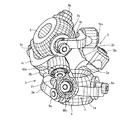
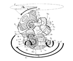
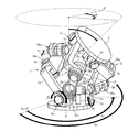
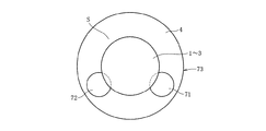
図1および図2に示す実施形態のリンク作動装置は、例えば、三次元空間における複雑な加工や物品の取り回し等の作業を高速かつ精密に実行するロボット関節などのリンク機構などに利用される三組のリンク機構1〜3を具備する。これら三組のリンク機構1〜3のそれぞれは幾何学的に同一形状をなす。
The link actuating device of the embodiment shown in FIG. 1 and FIG. 2 is used for, for example, a link mechanism such as a robot joint that performs high-speed and precise operations such as complicated processing and article handling in a three-dimensional space. A set of
図1および図2に示すように、各リンク機構1〜3は、入力部材4に回動自在に連結された入力側の端部リンク部材1a〜3aと、出力部材5に回動自在に連結された出力側の端部リンク部材1c〜3cと、両端部リンク部材1a〜3a,1c〜3cのそれぞれに回動自在に連結されて両端部リンク部材1a〜3a,1c〜3cを互いに連結する中央リンク部材1b〜3bとで構成され、四つの回転対偶部6a〜8a,6b1,6b2〜8b1,8b2,6c〜8cからなる三節連鎖構造をなす。
As shown in FIGS. 1 and 2, each of the
端部リンク部材1a〜3a,1c〜3cは球面リンク構造で、三組のリンク機構1〜3における球面リンク中心は一致しており、また、その中心からの距離も同じである。端部リンク部材1a〜3a,1c〜3cと中央リンク部材1b〜3bとの回転対偶部6b1,6b2〜8b1,8b2の連結軸は、ある交差角をもってもよいし、平行であってもよい。ただし、三組のリンク機構1〜3における中央リンク部材1b〜3bの形状は幾何学的に同一である。
The end link members 1a to 3a and 1c to 3c have a spherical link structure, and the spherical link centers in the three sets of
リンク機構1〜3において、端部リンク部材1a〜3a,1c〜3cの幾何学的形状が入力側と出力側で等しく、また、中央リンク部材1b〜3bについても入力側と出力側で形状が等しいとき、中央リンク部材1b〜3bの対称面に対して中央リンク部材1b〜3bと入出力部材4,5と連結される端部リンク部材1a〜3a,1c〜3cとの角度位置関係を入力側と出力側で同じにすれば、幾何学的対称性から入力部材4および入力側の端部リンク部材1a〜3aと出力部材5および出力側の端部リンク部材1c〜3cは同じに動き、入力側と出力側は同じ回転角になって等速回転することになる。この等速回転するときの中央リンク部材1b〜3bの対称面を等速二等分面という。
In the
このため、入出力部材4,5を共有する同じ幾何学形状のリンク機構1〜3を円周上に複数配置させることにより、複数のリンク機構1〜3が矛盾無く動ける位置として中央リンク部材1b〜3bが等速二等分面上のみの動きに限定され、これにより入力側と出力側は任意の作動角をとっても等速回転が得られる。
For this reason, by arranging a plurality of
この実施形態のリンク作動装置は、二つ以上の入力側の端部リンク部材1a〜3aの回転対偶部6a〜8aに、モータ等のアクチュエータを連結し、そのアクチュエータにより、端部リンク部材1a〜3aの回転角位置を制御することで、出力部材5に取り付けられた、例えばロボットの腕(図示せず)などの可動部位の姿勢を制御する。
In the link actuating device of this embodiment, an actuator such as a motor is connected to the
図1に示すリンク機構1〜3の基本的構成は、本出願人が先に提案した特願2003−40086に開示したものと同一であり、入出力部材4,5は、中心軸に貫通孔が形成され、外形を球面状としたドーナツ形状をなすリンクハブである。このリンク機構1〜3の各回転対偶部6a〜8a,6b〜8b,6c〜8cは、端部リンク部材1a〜3a,1c〜3cを片持ちで支持する構造を具備する。
The basic configuration of the
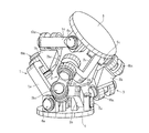
一方、図2に示すリンク機構1〜3の基本構成は、本出願人が先に提案した特願2003−388307に開示したものと同一であり、入出力部材4,5は、円盤状をなす。このリンク機構1〜3の各回転対偶部6a〜8a,6b1,6b2〜8b1,8b2,6c〜8cは、端部リンク部材1a〜3a,1c〜3cを両端支持する構造を具備する。
On the other hand, the basic configuration of the
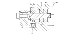
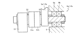
図3は、この実施形態における入力部材4と入力側の端部リンク部材1a〜3aの連結部分である回転対偶部6a〜8aを示す。この回転対偶部6a〜8aは、入力側端部リンク部材1a〜3aを回転自在に支承する軸10を軸受9a,9bを介して入力部材4に支持した構造を具備する。軸10の軸受9a,9bと反対側に位置する軸端部には回転伝達部材11が装着され、その回転伝達部材11としては、傘歯車やウォームなどが使用され、図示しないがリンク機構1〜3の端部リンク部材1a〜3aを駆動する姿勢制御用アクチュエータと連結される回転伝達部の一部を構成する。端部リンク部材1a〜3aおよび回転伝達部材11の軸10に対する回り止めとしては、止めねじやDカットを用いればよい。
FIG. 3 shows rotating
なお、このような軸受構造としたことにより、その連結部分での摩擦抵抗を抑えて回転抵抗の軽減を図ることができ、滑らかな動力伝達を確保できると共に耐久性を向上できる。前述の軸受構造としては、二個のラジアル玉軸受、アンギュラ玉軸受、ローラ軸受、すべり軸受、もしくは一個の複列アンギュラ玉軸受などを使用することが可能である。出力部材5は、図3の入力部材4と同一構造である。軸10の円周方向位置は等間隔でなくてもよいが、入出力部材4,5は同じ円周方向の位置関係とする必要がある。この入出力部材4,5は、三組のリンク機構1〜3で共有され、各軸10に端部リンク部材1a〜3a,1c〜3cが連結される。
By adopting such a bearing structure, it is possible to reduce the rotational resistance by suppressing the frictional resistance at the connecting portion, and to ensure smooth power transmission and improve the durability. As the above-described bearing structure, it is possible to use two radial ball bearings, angular ball bearings, roller bearings, slide bearings, or one double row angular ball bearing. The
図3に示す実施形態は、入力側端部リンク部材1a〜3aと入力部材4を連結する回転対偶部6a〜8aの軸10に設けられた被検出部31と、その被検出部31と対向する固定部位に設けられた検出部32とからなり、入力側端部リンク部材1a〜3aの回転範囲内における位置を検知する位置検出機構33を設けた構造を具備する。この位置検出機構33は、三組のリンク機構1〜3のうち、二つ以上のリンク機構に設置すればよい。入力側端部リンク部材1a〜3aと入力部材4を連結する回転対偶部6a〜8aの軸10に被検出部となるピン31を圧入し、そのピン31と対向する固定部位(例えば、入力部材4の所定部位)に検出部となる透過型フォトセンサ32を配設する。このような構造とすることにより、回転対偶部6a〜8aの軸10が回転すると、ピン31をフォトセンサ32で検知することが可能となる。このように位置検出機構33を設けたことにより、入力側端部リンク部材1a〜3aの一点位置を検知することによりリンク機構1〜3の姿勢を制御することが容易となる。
In the embodiment shown in FIG. 3, the detected
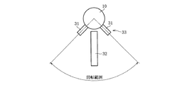
ピン31は、図4に示すように入力側端部リンク部材1a〜3aの回転限界位置と対応する二箇所に設けられている。その結果、入力側端部リンク部材1a〜3aが回転限界位置に達すると、フォトセンサ32からの検出信号に基づいてその位置でリンク機構1〜3の動作を停止させることができ、位置検出機構33がリミッタ機構としての機能を発揮する。このような位置検出機構33のリミッタ機能により、リンク作動装置の暴走を未然に防止することができる。
As shown in FIG. 4, the
なお、この実施形態では、被検出部としてのピン31を二箇所に設け、検出部としての透過型フォトセンサ32を一箇所に設けた場合であるが、ピン31を入力側端部リンク部材1a〜3aの一箇所に設け、透過型フォトセンサ32を入力側端部リンク部材1a〜3aの回転限界位置と対応する二箇所に設けるようにしてもよい。この場合、フォトセンサ32の設置スペースを確保する必要はあるが、二箇所の回転限界位置のうち、どちらの回転限界位置に達したかを判断できるため、その回転限界位置に達した時点でリンク機構1〜3の動作を停止させ、原点位置に復帰させて動作を再開することも可能である。
In this embodiment, the
また、前述の実施形態では、入力側端部リンク部材1a〜3aにピン31を設けた場合について説明したが、これ以外の構造として、図5に示すように入力側端部リンク部材1a〜3aに凹溝31’を設けて被検出部とすることも可能である。この場合、凹溝31’を検知する検出部としては、近接センサ32’を用いることが可能である。この位置検出機構33’についても、二つの凹溝31’に対して一つの近接センサ32’を設けたり、一つの凹溝31’に対して二つの近接センサ32’を設けることは、前述の実施形態と同様である。
Moreover, although the case where the
さらに、回転対偶部6a〜8aの軸10に設置する被検出部として磁石、固定部位に設置される検出部としてホールICのような磁場検出器を用いることも可能である。この場合、軸10の回転により、その軸10に設置された磁石が固定部位のホールICに近づくと、磁場が大きくなることから、ホールICからの検出信号を閾値処理することにより、入力側端部リンク部材1a〜3aの回転限界位置を検出することができる。
Furthermore, it is also possible to use a magnetic field detector such as a Hall IC as a magnet to be detected as a detected part installed on the
なお、図3および図5の実施形態では、位置検出機構33,33’を入力側端部リンク部材1a〜3aと回転伝達部材11との間に配設しているが、入力側端部リンク部材1a〜3aの回転限界位置を検知できるのであれば、その設置場所は任意である。また、この位置検出機構33,33’は、原点付回転センサ付軸受を使用することも可能である。
3 and 5, the
以上の実施形態では、位置検出機構33,33’の被検出部(ピン31や凹溝31’)を回転対偶部6a〜8aの軸10に設けた場合について説明したが、その被検出部41を入力側端部リンク部材1a〜3aに設け、検出部42を入力部材4に設けた構造とすることも可能であり、その実施形態を以下に説明する。なお、以下の実施形態では、二つの被検出部41に対して一つの検出部42を設けたり、一つの被検出部41に対して二つの検出部42を設けた構造とすることは、前述の実施形態と同様である。
In the above embodiment, the case where the detected portions (
図6に示す実施形態の位置検出機構43では、入力側端部リンク部材1a〜3aに被検出部41を設け、その被検出部41と対向する固定部位である入力部材4に検出部42を設けた構造を具備する。この被検出部41としては、前述したようにピン、凹溝、磁石等を用い、検出部42としては、透過型フォトセンサ、近接センサ、ホールIC等を用いればよい。
In the
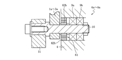
図6に示す実施形態における回転対偶部以外に、図7に示すような回転対偶部6a〜8aの構造にも適用可能である。この回転対偶部6a〜8aは、入力側端部リンク部材1a〜3aを支持する軸10の両端を軸受9a,9bにより回転自在に支持し、それら二つの軸受9a,9bを共通のハウジング12に組み込んだユニット構造を具備する。このように回転対偶部6a〜8aをユニット構造とすれば、リンク作動装置の組み立てが容易となる。
In addition to the rotating pair portion in the embodiment shown in FIG. 6, the present invention can be applied to the structure of the
図7に示す実施形態の位置検出機構43では、入力側端部リンク部材1a〜3aに被検出部41を設け、その被検出部41と対向する固定部位であるハウジング12に検出部42を設けた構造を具備する。この被検出部41としては、前述したようにピン、凹溝、磁石等を用い、検出部42としては、透過型フォトセンサ、近接センサ、ホールIC等を用いればよい。なお、被検出部41として、正弦波に着磁されたエンコーダのようなアブソリュート型エンコーダやレゾルバを設置したユニット構造とすることも可能である。
In the
この回転対偶部6a〜8aでは、軸10の中央部より片方へずれた位置に段差部13を設け、ナット14による締め付けでもって一方の軸受9bを固定し、入力側端部リンク部材1a〜3aと軸受9aとの間にスペーサ15を介在させ、ナット16による締め付けでもって他方の軸受9aを固定すると共に、入力側端部リンク部材1a〜3aの位置決めと軸受予圧を調整している。このようにガタ詰め手段を設ければ、回転対偶部6a〜8aにおける軸受9a,9bのガタツキを低減することができてリンク機構1〜3の剛性を高めることができる。
In the
なお、軸10に段差部13を設ける代わりにスペーサを設けた場合には、ナット14に代えてその軸端に段差部を設けた構造とすることも可能であり、その場合、回転対偶部6a〜8aでの軸受9a,9b、入力側端部リンク部材1a〜3aを軸10の一方向から組み付け可能となる。
In the case where a spacer is provided in place of the stepped
図8に示す実施形態は、リンク機構1〜3を駆動する姿勢制御用アクチュエータとの回転伝達部11と入力側端部リンク部材1a〜3aの間に逆入力フリーなトルクダイオード51a,51bを配設した構造を具備する。このトルクダイオード51a,51bの入力側、つまりトルクダイオード51aは、回転伝達部11の回転軸52に接続され、一方、トルクダイオードの出力側、つまりトルクダイオード51bは、回転対偶部6a〜8aの軸10に接続されている。このようにトルクダイオード51a,51bを設置することにより、姿勢制御用アクチュエータから入力側端部リンク部材1a〜3aの回転角度を制御することができ、また、出力側からの逆入力、つまり、アクチュエータにサーボがかかっていても、リンク機構側からも自由に動かすことができる。
In the embodiment shown in FIG. 8, reverse input-
従って、この回転対偶部6a〜8aの軸10あるいは入力側端部リンク部材1a〜3aに、図3〜図7に示すような位置検出機構33,33’,43を設ければ、入力側端部リンク部材1a〜3aの一定の位置(リンク機構1〜3が直立姿勢になる位置でも回転限界位置でも構わない)を検知することができる。トルクダイオード51a,51bに基づくリンク機構1〜3の姿勢制御に加えて、位置検出機構33,33’,43による入力側端部リンク部材1a〜3aの一点位置を検知することも可能となるので、電源投入時に手動でリンク機構側を適当に動かすだけで、イニシャライズを実行することができる。
Therefore, if
この時、リンク機構1〜3が静止状態であれば、出力部材5に付与される負荷などによりリンク機構1〜3は一定の姿勢を保持することができないため、トルクダイオード51a,51bを設置する部分の回転対偶部6a〜8aに摩擦クラッチを設けることが好ましい。このように回転対偶部6a〜8aの出力側に摩擦クラッチを設ければ、リンク機構1〜3が静止状態にあるとき、出力部材5に負荷が付与された場合でも、リンク機構1〜3を一定の姿勢に保持することが容易となる。
At this time, if the
また、トルクダイオード51a,51bの出力側に位置する回転対偶部6a〜8aの軸10に、入力側端部リンク部材1a〜3aの回転角度を検出する回転角度検出機構、例えばエンコーダ(インクリメンタル型、アブソリュート型)を設置すれば、出力部材側からの逆入力に対して、エンコーダの出力信号で入力側の端部リンク部材1a〜3aの回転角度を検知できるため、図9および図10に示すように折れ角θと旋回角φで規定される出力部材5の姿勢と入力側の端部リンク部材1a〜3aの回転角βnとの関係式(γは中央リンク部材1b〜3bの軸角、δは基準となる端部リンク部材に対する各端部リンク部材の円周方向離間角)、
cos(θ/2)sinβn−sin(θ/2)sin(φ+δn)cosβn+sin(γ/2)=0
による逆変換を利用して入力部材側に設置された姿勢制御用アクチュエータにより出力部材5の姿勢を制御することができる。また、回転角度検出機構を、出力部材5に設置された二軸方向の傾斜角を検知する二つの傾斜角センサとすれば、出力部材側からの逆入力、例えばリンク機構1〜3を手動で動かす場合、入力側の端部リンク部材1a〜3aの回転角度を検知できるため、傾斜角センサの出力信号から前述の関係式の逆変換を利用して、端部リンク部材1a〜3aの回転角度を算出することにより、出力部材5の姿勢を制御することができる。
Further, a rotation angle detecting mechanism for detecting the rotation angle of the input side end link members 1a to 3a, such as an encoder (incremental type,), is provided on the
cos (θ / 2) sinβn−sin (θ / 2) sin (φ + δn) cosβn + sin (γ / 2) = 0
The attitude of the
出力部材5の姿勢は、二自由度(折れ角θと旋回角φ)で規定することができ、出力部材5の姿勢(折れ角θと旋回角φ)と入力側の端部リンク部材の回転角βnとの関係を以下の式で規定することができる。
The posture of the
なお、下記の関係式におけるパラメータθは、入力部材4に対して出力部材5が垂直方向に傾斜した角度、パラメータφは、入力部材4に対して出力部材5が0°から水平方向に傾斜した角度、パラメータβ1,β2(リンク機構が三組であるため、そのうちの二つのパラメータで規定可能である)は、入力側の端部リンク部材1a〜3aの回転対偶部6a〜8aにおける回転角、パラメータγは、入力側の端部リンク部材1a〜3aに連結された中央リンク部材1b〜3bの回転対偶部6b1〜8b1と、出力側の端部リンク部材1c〜3cに連結された中央リンク部材1b〜3bの回転対偶部6b2〜8b2とがなす角度である。この関係式は、リンク機構1〜3が三組で、端部リンク部材1a〜3a,1c〜3cの円周方向位置が等間隔の場合である。
cos(θ/2)sinβ1−sin(θ/2)sinφcosβ1+sin(γ/2)=0
cos(θ/2)sinβ2−sin(θ/2)sin(φ+120°)cosβ2+sin(γ/2)=0
cos(θ/2)sinβ3−sin(θ/2)sin(φ+240°)cosβ3+sin(γ/2)=0
The parameter θ in the following relational expression is the angle at which the
cos (θ / 2) sinβ 1 −sin (θ / 2) sinφcosβ 1 + sin (γ / 2) = 0
cos (θ / 2) sinβ 2 −sin (θ / 2) sin (φ + 120 °) cosβ 2 + sin (γ / 2) = 0
cos (θ / 2) sinβ 3 −sin (θ / 2) sin (φ + 240 °) cosβ 3 + sin (γ / 2) = 0
これら二つ以上の方程式を解くことにより、前述の関係式の逆変換でもって出力部材5の姿勢を制御することができる。つまり、出力部材5の姿勢制御は、所定の姿勢を規定する目標値を関係式に入力することにより、その姿勢入力に対する入力側の端部リンク部材1a〜3aの回転角を求めることで実現できる。
By solving these two or more equations, the attitude of the
前述したように位置検出機構や回転角度検出機構としてアブソリュート型エンコーダを使用した場合、位置検出機構33,33’,43をリミッタとして機能させることが可能となり、また、イニシャライズ動作も不要となる。一般的なアブソリュート型エンコーダとしてはポテンショメータがあるが、その設置方法を工夫する必要があり、回転抵抗も生じるため、高精度を期待することが困難である。そのため、以下のようなアブソリュート型エンコーダを使用すればよい。
As described above, when an absolute encoder is used as the position detection mechanism or the rotation angle detection mechanism, the
前述の回転角度検出機構として、図11に示すように入力側端部リンク部材1a〜3aの回転範囲に合わせたレゾルバ61を用いる。リンク機構1〜3の最大折れ角が90°の場合、3Xまたは4Xのレゾルバ61を使用すればよい。つまり、リンク機構1〜3が取りうる最大折れ角をθmax、レゾルバ61の山数をXnumとすると、θmax≦360°/Xnumの関係が成立すればよい。レゾルバ61の場合、それぞれの山(X)の波形は正弦波となるため、入力側端部リンク部材1a〜3aの回転範囲内で一つの山波形が出るようにロータ62aを回転対偶部6a〜8aの軸10に設け、ステータ62bを入力部材4などの固定部位に設ければ、アブソリュート型エンコーダとして利用できる。このレゾルバ61は、レゾルバ付き回転センサ付き軸受として使用することも可能である。また、レゾルバ61を用いる代わりに、θmax≦360°/Xnumの関係を満足する磁気エンコーダを用いるようにしてもよい。この場合、Xnumは磁気エンコーダの山数、出力波形は正弦波状となる。
As the rotation angle detection mechanism described above, a
以上で説明したリンク機構にアクチュエータや各種センサ類を搭載する場合、以下のような構造を採用すればよい。つまり、図12および図13に示すように入力部材4の下方に位置し、姿勢制御用アクチュエータ71,72を収容したハウジング73の内部の空きスペースSを利用して、姿勢制御用アクチュエータ71,72を駆動させるための部品を含む電気回路部品を収容する。なお、電気回路部品は、入力側端部リンク部材1a〜3aの回転角度または位置を検知するセンサ信号を処理する基板や、姿勢制御用アクチュエータ71,72を制御するドライバを含む。
When an actuator or various sensors are mounted on the link mechanism described above, the following structure may be employed. That is, as shown in FIGS. 12 and 13, the
図12はリンク作動装置を上方から見た簡略図であるが、入力部材4の下方に位置するハウジング73には、駆動リンク部分である二つの入力側端部リンク部材1a〜3aを駆動する姿勢制御用アクチュエータ71,72が配置されている。そのため、従動リンク部分である残り一つの入力側端部リンク部材1a〜3aの下方に位置する空きスペースSを利用して、この空きスペースSに前述の電気回路部品を収容配置する。このようにすれば、ハウジング73内のスペースSを有効利用することができ、リンク作動装置のコンパクト化が図れ、シール性も向上する。また、リンク作動装置から外部へ引き出す配線を電源のみにすることも可能であり、配線が他の部品と接触して断線する可能性もなくなる。
FIG. 12 is a simplified view of the link actuating device as viewed from above, but the
また、リンク作動装置を、リンク機構1〜3を回転させる回転制御用アクチュエータ74を入力部材4側に設けた三自由度機構とした場合、入力部材4の中心軸(回転中心)に回転制御用アクチュエータ74を設置すればよい。このようにすれば、前述した従動の入力側端部リンク部材1a〜3aと対応するハウジング73内の空きスペースSを確保することができる。また、空きスペースSに、回転制御用アクチュエータ74を駆動するための部品を含む電気回路部品を収容することができる。
Further, when the link actuating device is a three-degree-of-freedom mechanism in which a rotation control actuator 74 for rotating the
図13に示す三自由度機構としたリンク作動装置では、入力部材4に回転軸75が接続されており、この回転軸75は、回転制御用アクチュエータ74を設置したベース76(ハウジング73の一部をなす)に軸受77を介して回転自在に支承され、カップリング78を介して回転制御用アクチュエータ74に接続されている。この回転制御用アクチュエータ74により入力部材4が回転する機構となっている。
In the link actuating device having a three-degree-of-freedom mechanism shown in FIG. 13, a rotating
また、二つの姿勢制御用アクチュエータ71,72を取り付けたフレーム79はスペーサ(図示せず)を介して入力部材4に固定されている。これにより、入力部材4とフレーム79は同時に回転することになり、二つの姿勢制御用アクチュエータ71,72はベース76の周りを回転することになる。この場合、姿勢制御用アクチュエータ71,72を駆動するための部品を含む電気回路部品を前述の空きスペースSに配置してフレーム79に取り付ければ、入力部材4と共に電気回路部品も回転するため、回転による配線の絡まりを減少させることができる。なお、回転制御用アクチュエータ74を駆動するための部品を含む電気回路部品については、固定部位に設置すればよい。
The
1〜3 リンク機構
1a〜3a,1c〜3c 端部リンク部材
1b〜3b 中央リンク部材
4 入力部材
5 出力部材
6a〜8a 回転対偶部
6b1,6b2〜8b1,8b2 回転対偶部
6c〜8c 回転対偶部
9a,9b 軸受
10 回転対偶部の軸
31,31’,41 被検出部
32,32’,42 検出部
33,33’,43 位置検出機構
51a,51b トルクダイオード
61 レゾルバ
73 ハウジング
71,72,74 アクチュエータ
1-3 linkage 1a~3a, 1c~3c
Claims (19)
cos(θ/2)sinβn−sin(θ/2)sin(φ+δn)cosβn+sin(γ/2)=0
による逆変換でもって入力部材側に設置された姿勢制御用アクチュエータにより前記出力部材の姿勢を制御可能とした請求項10に記載のリンク作動装置。 The rotation angle detection mechanism is an encoder provided on the shaft of the rotation pair, detects the rotation angle of the input side end link member with respect to the reverse input from the output member side, and the bending angle θ and the turning angle φ The relational expression between the attitude of the output member defined by the above and the rotation angle βn of the end link member on the input side (γ is the axial angle of the central link member, δ is the end link member of each end link member relative to the reference end link member Circumferential separation angle),
cos (θ / 2) sinβn−sin (θ / 2) sin (φ + δn) cosβn + sin (γ / 2) = 0
The link actuating device according to claim 10, wherein the posture of the output member can be controlled by a posture control actuator installed on the input member side by reverse conversion according to the above.
Priority Applications (1)
| Application Number | Priority Date | Filing Date | Title |
|---|---|---|---|
| JP2004118270A JP2005299828A (en) | 2004-04-13 | 2004-04-13 | Link operating device |
Applications Claiming Priority (1)
| Application Number | Priority Date | Filing Date | Title |
|---|---|---|---|
| JP2004118270A JP2005299828A (en) | 2004-04-13 | 2004-04-13 | Link operating device |
Publications (1)
| Publication Number | Publication Date |
|---|---|
| JP2005299828A true JP2005299828A (en) | 2005-10-27 |
Family
ID=35331599
Family Applications (1)
| Application Number | Title | Priority Date | Filing Date |
|---|---|---|---|
| JP2004118270A Withdrawn JP2005299828A (en) | 2004-04-13 | 2004-04-13 | Link operating device |
Country Status (1)
| Country | Link |
|---|---|
| JP (1) | JP2005299828A (en) |
Cited By (15)
| Publication number | Priority date | Publication date | Assignee | Title |
|---|---|---|---|---|
| JP2011183509A (en) * | 2010-03-09 | 2011-09-22 | Jun Kuchii | Rotation angle detecting device, jointed structure and mode taking-in device |
| WO2013047414A1 (en) * | 2011-09-29 | 2013-04-04 | Ntn株式会社 | Link actuating device |
| JP2013076427A (en) * | 2011-09-29 | 2013-04-25 | Ntn Corp | Link actuating device |
| WO2013065675A1 (en) * | 2011-11-04 | 2013-05-10 | Ntn株式会社 | Parallel link mechanism, constant velocity universal joint, and link actuator |
| WO2013069533A1 (en) * | 2011-11-07 | 2013-05-16 | Ntn株式会社 | Link operation device |
| JP2013096547A (en) * | 2011-11-04 | 2013-05-20 | Ntn Corp | Parallel link mechanism, constant velocity universal joint, and link actuation device |
| JP2013121652A (en) * | 2011-11-07 | 2013-06-20 | Ntn Corp | Parallel link mechanism, constant velocity universal joint and link actuator |
| WO2013176075A1 (en) * | 2012-05-22 | 2013-11-28 | Ntn株式会社 | Link actuation device |
| JP2014111290A (en) * | 2012-12-05 | 2014-06-19 | Kawasaki Heavy Ind Ltd | Parallel link robot |
| JP2014119069A (en) * | 2012-12-18 | 2014-06-30 | Ntn Corp | Link actuation device |
| US8831802B2 (en) | 2009-07-10 | 2014-09-09 | Yamaha Hatsudoki Kabushiki Kaisha | Boat propelling system |
| JP2015025530A (en) * | 2013-07-29 | 2015-02-05 | Ntn株式会社 | Link actuator |
| CN105598954A (en) * | 2016-03-24 | 2016-05-25 | 褚宏鹏 | Two-rotation parallel mechanism with large working space |
| JP2016124067A (en) * | 2014-12-26 | 2016-07-11 | 三菱プレシジョン株式会社 | Calibration apparatus and calibration method for parallel link mechanism |
| US9808932B2 (en) | 2013-03-26 | 2017-11-07 | Ntn Corporation | Linking apparatus control device |
-
2004
- 2004-04-13 JP JP2004118270A patent/JP2005299828A/en not_active Withdrawn
Cited By (21)
| Publication number | Priority date | Publication date | Assignee | Title |
|---|---|---|---|---|
| US8831802B2 (en) | 2009-07-10 | 2014-09-09 | Yamaha Hatsudoki Kabushiki Kaisha | Boat propelling system |
| JP2011183509A (en) * | 2010-03-09 | 2011-09-22 | Jun Kuchii | Rotation angle detecting device, jointed structure and mode taking-in device |
| WO2013047414A1 (en) * | 2011-09-29 | 2013-04-04 | Ntn株式会社 | Link actuating device |
| JP2013076427A (en) * | 2011-09-29 | 2013-04-25 | Ntn Corp | Link actuating device |
| US9746037B2 (en) | 2011-09-29 | 2017-08-29 | Ntn Corporation | Link actuating device |
| CN103906947A (en) * | 2011-11-04 | 2014-07-02 | Ntn株式会社 | Parallel linkages, constant velocity joints and link action devices |
| JP2013096547A (en) * | 2011-11-04 | 2013-05-20 | Ntn Corp | Parallel link mechanism, constant velocity universal joint, and link actuation device |
| US9316266B2 (en) | 2011-11-04 | 2016-04-19 | Ntn Corporation | Parallel link mechanism, constant velocity universal joint, and link actuator |
| WO2013065675A1 (en) * | 2011-11-04 | 2013-05-10 | Ntn株式会社 | Parallel link mechanism, constant velocity universal joint, and link actuator |
| CN103906947B (en) * | 2011-11-04 | 2016-11-02 | Ntn株式会社 | Parallel linkages, constant velocity joints and link action devices |
| JP2017110815A (en) * | 2011-11-07 | 2017-06-22 | Ntn株式会社 | Parallel link mechanism, constant velocity universal joint and link operation device |
| WO2013069533A1 (en) * | 2011-11-07 | 2013-05-16 | Ntn株式会社 | Link operation device |
| JP2013121652A (en) * | 2011-11-07 | 2013-06-20 | Ntn Corp | Parallel link mechanism, constant velocity universal joint and link actuator |
| US9394979B2 (en) | 2011-11-07 | 2016-07-19 | Ntn Corporation | Link actuating device |
| WO2013176075A1 (en) * | 2012-05-22 | 2013-11-28 | Ntn株式会社 | Link actuation device |
| JP2014111290A (en) * | 2012-12-05 | 2014-06-19 | Kawasaki Heavy Ind Ltd | Parallel link robot |
| JP2014119069A (en) * | 2012-12-18 | 2014-06-30 | Ntn Corp | Link actuation device |
| US9808932B2 (en) | 2013-03-26 | 2017-11-07 | Ntn Corporation | Linking apparatus control device |
| JP2015025530A (en) * | 2013-07-29 | 2015-02-05 | Ntn株式会社 | Link actuator |
| JP2016124067A (en) * | 2014-12-26 | 2016-07-11 | 三菱プレシジョン株式会社 | Calibration apparatus and calibration method for parallel link mechanism |
| CN105598954A (en) * | 2016-03-24 | 2016-05-25 | 褚宏鹏 | Two-rotation parallel mechanism with large working space |
Similar Documents
| Publication | Publication Date | Title |
|---|---|---|
| US7472622B2 (en) | Linkage system | |
| US8251863B2 (en) | Continuously variable transmission with multiple outputs | |
| JP2005299828A (en) | Link operating device | |
| US11364626B2 (en) | 6-dof parallel robot with a double-gyroscopic component | |
| JP5528207B2 (en) | Link actuator | |
| TWI418452B (en) | A wrist unit for an industrial robot | |
| TWI294820B (en) | Link drive mechanism and industrial robot using the same | |
| US20080028881A1 (en) | Linkage System | |
| JP2002341076A (en) | Angle adjustment table device | |
| JP7022008B2 (en) | Link actuator | |
| JP2012171072A (en) | Robot, robot system, and rotating electrical machine | |
| EP2152477B1 (en) | Robotic manipulator using rotary drives | |
| JPH10118966A (en) | Parallel robot | |
| JP6104701B2 (en) | Link actuator | |
| KR101179816B1 (en) | Joint module for robot and joint system for robot having the same | |
| CN104071569A (en) | Gripping device | |
| JP2005226777A (en) | Link operating device | |
| JP2004009276A (en) | Link operating device | |
| WO2017217415A1 (en) | Joint unit | |
| WO2004073935A1 (en) | Link-actuating device | |
| US9475190B2 (en) | Robot | |
| WO2019065873A1 (en) | Articulated robot and method for operating same | |
| JP2005147333A (en) | Link operating device | |
| JP6352054B2 (en) | Parallel link mechanism and link actuator | |
| JP4476603B2 (en) | Link actuator |
Legal Events
| Date | Code | Title | Description |
|---|---|---|---|
| A300 | Withdrawal of application because of no request for examination |
Free format text: JAPANESE INTERMEDIATE CODE: A300 Effective date: 20070703 |