JP2005299977A - Cooker - Google Patents
Cooker Download PDFInfo
- Publication number
- JP2005299977A JP2005299977A JP2004114020A JP2004114020A JP2005299977A JP 2005299977 A JP2005299977 A JP 2005299977A JP 2004114020 A JP2004114020 A JP 2004114020A JP 2004114020 A JP2004114020 A JP 2004114020A JP 2005299977 A JP2005299977 A JP 2005299977A
- Authority
- JP
- Japan
- Prior art keywords
- light
- heated
- heating chamber
- heating
- color
- Prior art date
- Legal status (The legal status is an assumption and is not a legal conclusion. Google has not performed a legal analysis and makes no representation as to the accuracy of the status listed.)
- Pending
Links
Images

Landscapes
- Electric Ovens (AREA)
- Electric Stoves And Ranges (AREA)
Abstract
【課題】加熱調理器の内部の被加熱物が実際の色と同じ色に見えるようにして、外部から内部の被加熱物の視認性を向上させる。
【解決手段】加熱室2内に蛍光灯や太陽光と同じ色温度が3000〜5000Kの光を照射する。また、被加熱物3を載せるテーブル9を支持する複数の重量センサ10を備えることで被加熱物3の位置を検知できる機能と色温度が3000〜5000Kの光を照射できる照明手段と、その照射方向を移動できる駆動手段を備え被加熱物3の在る位置に光を向けることによって、加熱室2内の被加熱物3の視認性を向上させる。
【選択図】 図1
An object of the present invention is to improve the visibility of an object to be heated from the outside by making the object to be heated inside the heating cooker look the same color as the actual color.
The heating chamber 2 is irradiated with light having a color temperature of 3000 to 5000 K which is the same as that of a fluorescent lamp or sunlight. Moreover, the illumination means which can irradiate the light whose color temperature is 3000-5000K, the function which can detect the position of the to-be-heated material 3 by providing the several weight sensor 10 which supports the table 9 on which the to-be-heated material 3 is mounted, and its irradiation The visibility of the object to be heated 3 in the heating chamber 2 is improved by providing driving means that can move the direction and directing light to the position where the object to be heated 3 exists.
[Selection] Figure 1
Description
本発明は照明手段を搭載した加熱調理器に関するものである。 The present invention relates to a cooking device equipped with illumination means.
電子レンジ等の加熱調理器は加熱にマイクロ波を利用するため、ドアに付けられた窓ガラスから電磁波を外部に漏らさないために、窓ガラス部に電磁波を遮蔽するためのパンチング孔加工を施した金属板が設けられている。そのためドアの窓からは、周囲からの明りが加熱室内に届き難いため加熱室は大変暗く、そのため、加熱室に入れた被加熱物の加熱状態を見えるようにするために、庫内を照らす庫内灯が設けられている。 In order to prevent electromagnetic waves from leaking outside from the window glass attached to the door, heating cookers such as microwave ovens have punched holes to shield the electromagnetic waves from the window glass attached to the door. A metal plate is provided. For this reason, the heating chamber is very dark because it is difficult for the light from the surroundings to reach the heating chamber from the door window. Therefore, in order to see the heating state of the object to be heated in the heating chamber, the chamber is illuminated. An interior light is provided.
従来、家庭用の加熱調理器の庫内灯に使用される光源は一般的に白熱電球が多く使われている。そして、この庫内灯の設置も、ドアの窓同様に電磁波を外部に漏らさないようにパンチング孔加工を施した加熱室の外側に設置されている。 Conventionally, incandescent bulbs are generally used as light sources used for interior lamps of domestic cooking devices. The interior lamp is also installed outside the heating chamber in which punching holes have been processed so as not to leak electromagnetic waves to the outside like the door window.
加熱室を照らす庫内灯の明りもパンチング孔を通して照らすために遮断される光もあり加熱室内は暗く、そのため加熱室を明るくする方法として、特許文献1のように加熱室天面にゆるやかな曲面の反射板を設けて、その反射で加熱室中央部分に光を集めて明るくする手法や、特許文献2に記載のように、光の照射角度を広くして加熱室内に効率よく多くの光を取り入れる方法などがある。 There is also light from the interior lamp that illuminates the heating chamber and light that is blocked to illuminate through the punching hole, and the heating chamber is dark. Therefore, as a method for brightening the heating chamber, a gently curved surface on the top surface of the heating chamber as in Patent Document 1 The reflection plate collects light in the central part of the heating chamber by the reflection, and as described in Patent Document 2, the light irradiation angle is widened so that a large amount of light is efficiently emitted into the heating chamber. There are ways to incorporate it.
しかし、照射方法を変える事によって加熱室内が明るくなったとしても、電球から照射される光の波長は変化しない。 However, even if the heating chamber becomes brighter by changing the irradiation method, the wavelength of light emitted from the light bulb does not change.
そのため、一般的に庫内灯として使用されている白熱電球を使用した加熱調理器において、庫内に載置した被加熱物を外側から見た場合の被加熱物の色は、台所や食卓で見る実際の被加熱物の色とは違って見える場合が多い。 Therefore, in a cooking device that uses an incandescent light bulb that is generally used as an interior light, the color of the object to be heated when viewed from the outside is the kitchen or dining table. In many cases, it looks different from the color of the actual object to be heated.
それは、庫内灯に使用される白熱電球の色温度が低いためである。一般に日中の太陽光の色温度は約6500K、蛍光灯の色温度は白色タイプで約4000Kあるのに比べて白熱電球の色温度は約2800K前後である。色温度が高いと白色から青白い色へと青味が強くなり、そして低いと黄色から赤色になる。庫内灯の白熱電球から放される色は黄色から赤味かかった色をしているため、茶色や黄土色の焼き色やこげなどの色の変化を判別しにくくしている。 This is because the incandescent light bulb used for the interior lamp has a low color temperature. In general, the color temperature of sunlight during the day is about 6500K, and the color temperature of fluorescent lamps is about 4000K for the white type, whereas the color temperature of incandescent bulbs is about 2800K. When the color temperature is high, the bluish color increases from white to pale, and when the color temperature is low, the color changes from yellow to red. The color emitted from the incandescent lamp of the interior light is yellow to reddish, making it difficult to discern changes in colors such as brown or ocher baked or dark.
そのため、クッキーやパンなどのオーブン調理を行う場合、焼き色を見ながら火力や焼き時間を調節するが、現行の白熱電球を使用した加熱調理器では焼き色の判別が難しい場合があり、その時は、ドアを一旦開けて焼き具合を判別しなければならない。 Therefore, when cooking ovens such as cookies and bread, adjust the heating power and baking time while watching the baking color, but it may be difficult to distinguish the baking color with the current cooking device using incandescent light bulb, , You have to open the door and determine how it is baked.
しかし、オーブン調理の途中でドアを開けると庫内が冷えてしまい、調理時間が長くなったり、調理の失敗の原因になるなど問題も多く、調理するのに大変不便である。 However, if the door is opened during cooking in the oven, the inside of the refrigerator is cooled, and there are many problems such as a longer cooking time and a cause of cooking failure, which is very inconvenient to cook.
本発明の請求項1では、加熱室に光を照射する該照明手段により色温度が3000〜5000Kの光を加熱室に照射するものである。 In the first aspect of the present invention, the heating chamber is irradiated with light having a color temperature of 3000 to 5000 K by the illuminating means for irradiating the heating chamber with light.
また、請求項2では、前記照明手段が色温度3000〜5000Kの光を発光する光源である。 According to a second aspect of the present invention, the illumination means is a light source that emits light having a color temperature of 3000 to 5000K.
また、請求項3では、前記照明手段を庫内灯とフィルタにより構成することである。 According to a third aspect of the present invention, the illumination means is composed of an interior lamp and a filter.
さらに、請求項4では、被加熱物を載置するテーブルと、そのテーブルを支持する複数の重量センサを備えた被加熱物の重量と位置を検出できる機能と、色温度3000〜5000Kの光を加熱室に照射する照明手段と、該照明手段の光の方向を制御する駆動手段を備え、被加熱物が載置された位置を検出して、駆動手段により被加熱物の位置に照明手段の光を向けることである。 Further, in claim 4, a table for placing the object to be heated, a function of detecting the weight and position of the object to be heated provided with a plurality of weight sensors for supporting the table, and light having a color temperature of 3000 to 5000K are provided. Illuminating means for irradiating the heating chamber and driving means for controlling the direction of the light of the illuminating means are detected, the position where the object to be heated is placed is detected, and the driving means detects the position of the illuminating means at the position of the object to be heated. To direct light.
本発明によれば、請求項1では、窓越しからでも加熱室の被加熱物が見やすく、色が判別しやすく、調理しやすい加熱調理器を構成できる。 According to the present invention, according to the first aspect, it is possible to configure a heating cooker that makes it easy to see the object to be heated in the heating chamber even through the window, to easily distinguish the color, and to cook easily.
また、請求項2では、庫内灯として取り付けるだけで容易に、見やすく調理しやすい加熱調理器を構成できる。 Moreover, in Claim 2, the heating cooker which can be easily seen and cooked easily can be comprised only by attaching as an interior lamp.
また、請求項3では、安い製造コストで、見やすい加熱調理器を構成できる。 Further, in claim 3, an easy-to-see heating cooker can be configured at a low manufacturing cost.
さらに、請求項4では、加熱室内のどんな位置に被加熱物を置いても該被加熱物を見やすくすることができ、調理がしやすい加熱調理器を構成できる。 Further, according to the fourth aspect of the present invention, it is possible to make the heated object easy to see no matter where the heated object is placed in the heating chamber, and it is possible to configure a cooking device that is easy to cook.
本発明の各実施例を以下に説明する。 Examples of the present invention will be described below.
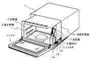
図1は本発明の第一実施例における加熱調理器の斜視断面図であり、加熱室2底面に被加熱物3を載置して加熱調理するターンテーブルレス式オーブンレンジである。 FIG. 1 is a perspective cross-sectional view of a heating cooker according to a first embodiment of the present invention, which is a turntableless microwave oven in which an object to be heated 3 is placed on the bottom surface of a heating chamber 2 for cooking.
本発明による加熱調理器ではキャビネット1の内側に被加熱物3を収納し加熱調理を行う金属壁の加熱室2が設けられ、前面には加熱室2に被加熱物3を出し入れする開閉可能なドア11が設けられている。 The heating cooker according to the present invention is provided with a heating chamber 2 of a metal wall for storing the object to be heated 3 inside the cabinet 1 for cooking, and opening and closing the heating object 2 in and out of the heating chamber 2 can be opened and closed. A door 11 is provided.
加熱室2の下方には加熱手段の一つであるマグネトロン13、マイクロ波を制御するアンテナ(図示せず)とアンテナを回転させるモータ(図示せず)、電子部品14を収納した機械室12を持ち、マグネトロン13から発するマイクロ波を制御することで加熱室2に載置した被加熱物3を加熱する。また、図示していないが、加熱室2上部、下部及び後部等にはオーブン調理をする場合の加熱手段としてヒータが設けられている。
Below the heating chamber 2, there is a
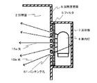
ここで、照明手段である庫内灯4周辺の拡大断面図を図2に示す。 Here, FIG. 2 shows an enlarged cross-sectional view of the vicinity of the interior lamp 4 which is the illumination means.
従来の構成では加熱室壁面6の外側に庫内灯4、反射板7があり、加熱室壁面6に開いたパンチング孔61を透過した光が加熱室2に照射されていた。 In the conventional configuration, the interior lamp 4 and the reflection plate 7 are provided outside the heating chamber wall surface 6, and the light transmitted through the punching holes 61 opened in the heating chamber wall surface 6 is irradiated to the heating chamber 2.
これに対し、本発明の実施例は庫内灯4と加熱室2の間の加熱室壁面6に光を透過しマイクロ波を遮蔽するパンチング孔61にフィルタ5が設けられ、その外側に庫内灯4と反射板7が設けられている構成である。 On the other hand, in the embodiment of the present invention, the filter 5 is provided in the punching hole 61 that transmits light to the heating chamber wall surface 6 between the interior lamp 4 and the heating chamber 2 and shields the microwaves, and the inside of the chamber is outside the chamber. The lamp 4 and the reflection plate 7 are provided.
ここで、フィルタ5は加熱室2に照射される光の色調および光量を調整するもので、庫内灯4から照射された光15aと庫内灯4から照射され反射板7により反射された光15bが、フィルタ5、パンチング孔61を通過し、加熱室2に色温度3000〜5000Kの太陽光に近い白色光を照射するようにする。 Here, the filter 5 adjusts the color tone and light quantity of the light irradiated to the heating chamber 2, and the light 15 a irradiated from the interior lamp 4 and the light irradiated from the interior lamp 4 and reflected by the reflecting plate 7. 15b passes the filter 5 and the punching hole 61, and irradiates the heating chamber 2 with white light close to sunlight having a color temperature of 3000 to 5000K.
ここで、3000〜5000Kの色温度は、本出願人の実調理試験で加熱室2に照射される色温度を変えて調べた結果において、ドア11の外から焼きムラ等が最も忠実に表現されていたときの色温度である。 Here, as for the color temperature of 3000 to 5000K, the unevenness of baking is most faithfully expressed from the outside of the door 11 as a result of examining the color temperature irradiated to the heating chamber 2 in the actual cooking test of the present applicant. It is the color temperature when
色温度3000K以下では被加熱物3の茶色から黄土色の焼き色が判別しにくく、色温度5000K以上では加熱室2が青っぽく暗い色になってしまうため、調理をしやすい加熱室2の色としてはあまり適切ではない。 When the color temperature is 3000K or lower, it is difficult to distinguish the brown to ocher color of the article 3 to be heated. When the color temperature is 5000K or higher, the heating chamber 2 becomes a bluish and dark color. Is not very appropriate.
また、本実施例ではフィルタ5と庫内灯4による構成を示すが、もちろん、フィルタ5を設けない場合でも色温度3000〜5000Kの白色光を照射する光源を用いることで、加熱室2に白色光を照射することができる。 Moreover, although the present Example shows the structure by the filter 5 and the interior lamp 4, of course, even when the filter 5 is not provided, the heating chamber 2 is whitened by using a light source that emits white light having a color temperature of 3000 to 5000K. Light can be irradiated.
この色温度3000〜5000Kの白色光を照射する光源としては、ハロゲン電球や蛍光灯などがある。 Examples of a light source that emits white light having a color temperature of 3000 to 5000 K include a halogen bulb and a fluorescent lamp.
例えば、色温度が3000K以下の白熱電球を庫内灯4に用いた場合、庫内灯4から照射される光は赤〜黄色の光(波長580〜780nm程度)が多く、赤〜黄色がかった光が照射されるが、フィルタ5により可視光の長波長である赤〜黄色の光をカットするか、またはフィルタ5により青〜紫色の光(波長380〜500nm程度)を加えることにより、波長のバランスが良くなり、加熱室2には色温度が3000〜5000Kと高く太陽光に近い白色光を照射することができる。 For example, when an incandescent bulb having a color temperature of 3000 K or less is used for the interior lamp 4, the light emitted from the interior lamp 4 is mostly red to yellow light (wavelength of about 580 to 780 nm), and red to yellowish. Although light is irradiated, the filter 5 cuts red to yellow light, which is a long wavelength of visible light, or blue to purple light (wavelength of about 380 to 500 nm) is added by the filter 5 to reduce the wavelength. The balance is improved, and the heating chamber 2 can be irradiated with white light having a high color temperature of 3000 to 5000 K and close to sunlight.
つまり、フィルタ5の色を変更することにより、加熱室2内に照射する光の色調を容易に変更することができるため、使用状況に応じた照射光を選ぶことが可能である。 That is, by changing the color of the filter 5, the color tone of the light irradiated into the heating chamber 2 can be easily changed, so that it is possible to select the irradiation light according to the use situation.
また、フィルタ5の色はグラデーションなどで色あいに変化をつけることで、多色の光を加熱室内に照射することができる。 Moreover, the color of the filter 5 can change the color tone by gradation or the like, so that multicolor light can be irradiated into the heating chamber.
例えば、明るくなりがちな庫内灯4に近い側は光量を抑え目に、遠い側は明るめにし、庫内灯4の位置に寄らず全面の色ムラを無くして全面の照度が均一になるように光を照射することができる。 For example, the side closer to the interior light 4 that tends to be brighter is reduced in light amount on the side, and the far side is made brighter so that the illumination on the entire surface becomes uniform without any color unevenness regardless of the position of the interior light 4. Can be irradiated with light.
また、フィルタの代わりにレンズやミラーなどを設置することにより光の方向を変えることで、全面まんべんなく明るく光を照射したり、常にテーブルの一部を明るく照射したりすることもできる。 In addition, by changing the direction of light by installing a lens or a mirror instead of a filter, it is possible to irradiate light evenly over the entire surface, or always irradiate part of the table brightly.
さらに、該レンズやミラーに本発明のフィルタ機能を付加してもよい。 Furthermore, the filter function of the present invention may be added to the lens or mirror.
また、既存の庫内灯4の周辺構造にフィルタ5を設置するだけの簡単な構造なので、安い製造コストで容易に加熱調理器に搭載できる構造である。 Moreover, since it is a simple structure which only installs the filter 5 in the surrounding structure of the existing interior lamp 4, it is a structure which can be easily mounted in a heating cooker at a low manufacturing cost.
以下、上記構成における本実施例の加熱調理器の動作について説明する。 Hereinafter, the operation of the cooking device according to the present embodiment having the above-described configuration will be described.
加熱室2に白色光を照射することにより、調理中でも加熱室2内の被加熱物3の色が調理者からよく見え、調理がしやすい。 By irradiating the heating chamber 2 with white light, the color of the article 3 to be heated in the heating chamber 2 can be clearly seen by the cooker during cooking, and cooking is easy.
例えば、調理中にドア11を通して加熱室2内部の被加熱物3の様子を見る場合、色温度3000K以下の一般的な白熱電球の庫内灯4のみでは台所や食卓の蛍光灯の下で見る被加熱物3とは異なり赤〜黄色がかった色合いに見えるが、フィルタを設けて加熱室2内に白色光を照射することで、加熱室2内の被加熱物3の色が、取り出した時の被加熱物3と同じ色合いに見える。 For example, when the state of the object to be heated 3 inside the heating chamber 2 is viewed through the door 11 during cooking, only the interior lamp 4 of a general incandescent bulb having a color temperature of 3000 K or less is viewed under a fluorescent lamp in a kitchen or a table. Unlike the heated object 3, it looks reddish-yellowish, but when the filter is provided and the heating chamber 2 is irradiated with white light, the color of the heated object 3 in the heating chamber 2 is taken out. Appears to be the same color as the object to be heated 3.
特に、クッキーやパンなどのオーブン調理をする場合、従来の構造では調理中にドア11を通して見る焼き色が実際の焼き色と違っているため、調理の途中でいちいちドア11を開けて焼き色を確認する必要があった。しかし、ドア11を一旦開けると加熱室2の温度が下がってしまい、設定温度に戻るのに時間がかかり、結果として調理時間が長くなってしまうことがあった。また、ピザなどの高温で一気に調理する食品の場合、一度加熱室2の温度を下げてしまったことによって、美味しく焼きあがらないことがあった。 In particular, when oven-cooking cookies, bread, etc., the grilling color seen through the door 11 during cooking is different from the actual grilling color in the conventional structure. It was necessary to confirm. However, once the door 11 is opened, the temperature of the heating chamber 2 decreases, and it takes time to return to the set temperature, resulting in a longer cooking time. In addition, in the case of foods that are cooked at a high temperature, such as pizza, the temperature of the heating chamber 2 has been lowered once, so that it may not be deliciously baked.
そこで、本発明の庫内灯構造を持つ加熱調理器を使用することにより、これまでのようにいちいちドア11を開けて調理途中の様子を確認する必要がなく、ドア11の窓を通して外から焼き色を確認しながら調理できるため、調理途中の状況が把握しやすいことから調理が簡単になり、失敗が少なくなる。 Therefore, by using the heating cooker having the interior lamp structure of the present invention, it is not necessary to open the door 11 one by one and confirm the state of cooking in the middle as before, and baked from the outside through the window of the door 11. Since cooking can be performed while checking the color, cooking is easy because the situation during cooking is easy to grasp, and fewer failures occur.
また、レンジ調理においても、加熱室2に照射される光の色が白色光ではない場合に比べて、白色光が照射される場合では加熱室2内の様子が見やすくなるため、実際の野菜の色が見えるため、ゆで具合が確認しやすい上、被加熱物3から発生する蒸気の様子が良く見えるため被加熱物3の加熱状態が把握しやすい。調理の途中でドア11を開けて被加熱物3の確認をせずに追加熱等ができるなど、外部からの被加熱物3の視認性が向上することにより様々なことに便利である。 In addition, in the cooking range, the state of the heating chamber 2 is easier to see when white light is irradiated than when the color of the light irradiated to the heating chamber 2 is not white light. Since the color is visible, it is easy to check the boiled condition, and the state of the steam generated from the heated object 3 can be seen well, so that the heating state of the heated object 3 can be easily grasped. It is convenient for various things by improving the visibility of the object to be heated 3 from the outside, such as opening the door 11 during cooking and performing additional heat without checking the object to be heated 3.
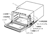
本発明の加熱調理器の第二実施例であるターンテーブルレス式オーブンレンジを図3に示す。 FIG. 3 shows a turntableless type microwave oven as a second embodiment of the cooking device of the present invention.
本実施例は、被加熱物3の置かれた位置を検知して被加熱物3を集中的に明るく照らす方法である。 The present embodiment is a method of illuminating the heated object 3 intensively and brightly by detecting the position where the heated object 3 is placed.
図において、加熱室2の底面に被加熱物3を載置するテーブル9が設置されている。 In the figure, a table 9 on which the object to be heated 3 is placed is installed on the bottom surface of the heating chamber 2.
そのテーブル9の下面は図4に示すように複数個の重量センサ10によって支持されている構成となっている。 The lower surface of the table 9 is supported by a plurality of weight sensors 10 as shown in FIG.
ここで、重量センサ10の数としては、例えば、図4に示す10a、10b、10c、10eによる4点支持でも良いが、安定してテーブル9を支持できる10a、10b、10dの3点支持がより望ましい。 Here, as the number of weight sensors 10, for example, four-point support by 10a, 10b, 10c, and 10e shown in FIG. 4 may be used, but three-point support of 10a, 10b, and 10d that can stably support the table 9 is possible. More desirable.
本発明では、多数の重量センサを用いて、各重量センサの重量検出値の重量比で被加熱物3の位置を検出することができる。そこで、指向性を持った庫内灯4の照射方向を変化させる駆動手段であるアクチュエータ8によって庫内灯4の光を照射する方向を変えることによって、被加熱物3の置かれた位置に応じた最適な照明を行うことができる。 In the present invention, the position of the object to be heated 3 can be detected by using the weight ratio of the weight detection values of the respective weight sensors using a number of weight sensors. Therefore, by changing the direction in which the light of the interior lamp 4 is irradiated by the actuator 8 which is a driving means for changing the irradiation direction of the interior lamp 4 having directivity, the position of the object to be heated 3 is changed. Optimal lighting can be performed.
ここで、アクチュエータ8は小型モータなどを利用することが一般的であるが、庫内灯4の角度を変えることができるものであれば何でも良い。 Here, the actuator 8 generally uses a small motor or the like, but may be anything as long as the angle of the interior lamp 4 can be changed.
また、駆動方向は一軸でも良いが、二軸駆動できることがより望ましい。 Further, the driving direction may be uniaxial, but it is more desirable that it can be driven biaxially.
さらに、庫内灯4付近が熱くなる場合は、該アクチュエータ8に付随してファン等の冷却手段を設け、庫内灯4を効率よく冷却するようにしても良い。 Further, when the vicinity of the interior lamp 4 becomes hot, a cooling means such as a fan may be provided in association with the actuator 8 so that the interior lamp 4 can be efficiently cooled.
また、庫内灯4に指向性を持たせる方法としては、庫内灯4に指向性を持つ光源を使っても良いし、特異な形状の反射板(図示せず)を用いて一定方向を照らすようにしても良いし、またはレンズ等の光の方向を変えることができる物体を加熱室2と庫内灯4の間に設けることで、光の方向を調節しても良い。 Moreover, as a method of giving directivity to the interior lamp 4, a light source having directivity may be used for the interior lamp 4, or a certain direction is set using a reflector (not shown) having a specific shape. The direction of light may be adjusted by providing an object that can change the direction of light, such as a lens, between the heating chamber 2 and the interior lamp 4.
従来の加熱調理器では、加熱室2の明るさにムラがあり、ちょうど被加熱物3を置いた位置が暗くて見にくい場合もあったが、本発明によるレンジを使用することで、被加熱物3を置いた位置に集中して光を照射することができるため、どこに被加熱物3を置いても調理中に明るく見やすい加熱調理器を提供できる。 In the conventional cooking device, the brightness of the heating chamber 2 is uneven, and the position where the heated object 3 is placed is sometimes dark and difficult to see, but by using the range according to the present invention, the heated object Since the light can be radiated in a concentrated manner at the position where 3 is placed, it is possible to provide a heating cooker that is bright and easy to see during cooking no matter where the article 3 is placed.
また、角皿などを使用する場合や、テーブル9で重量を検出できない場合においては、外部から最も見やすい方向に庫内灯4をアクチュエータ8のマニュアル操作で駆動し、角皿に載っている食品の外部からの視認性を良くすることによって、調理しやすい加熱調理器を提供する。 In addition, when a square dish or the like is used, or when the weight cannot be detected by the table 9, the interior lamp 4 is driven by the manual operation of the actuator 8 in the direction that is most easily visible from the outside, and the food on the square dish is Provided is a cooking device that is easy to cook by improving visibility from the outside.
2・・・加熱室
3・・・被加熱物
4・・・庫内灯
5・・・フィルタ
61・・・パンチング孔
8・・・アクチュエータ
9・・・テーブル
10・・・重量センサ
11・・・ドア
2 ... Heating chamber 3 ... Object to be heated 4 ... Interior light 5 ... Filter 61 ... Punching hole 8 ... Actuator 9 ... Table 10 ... Weight sensor 11 ... ·door
Claims (4)
A heating chamber (2) for storing the object to be heated (3), a heating means for heating the object to be heated (3), a table (9) for placing the object to be heated (3), and the table (9) A plurality of weight sensors (10) for supporting the light, illumination means for irradiating the heating chamber (2) with light having a color temperature of 3000 to 5000K, and drive means for controlling the light irradiation direction of the illumination means. The position on the table (9) on which the object to be heated (3) is placed is detected by the weight sensor (10), and the light from the illumination means is directed to the placement position of the object to be heated (3) by the driving means. A cooking device characterized by that.
Priority Applications (1)
| Application Number | Priority Date | Filing Date | Title |
|---|---|---|---|
| JP2004114020A JP2005299977A (en) | 2004-04-08 | 2004-04-08 | Cooker |
Applications Claiming Priority (1)
| Application Number | Priority Date | Filing Date | Title |
|---|---|---|---|
| JP2004114020A JP2005299977A (en) | 2004-04-08 | 2004-04-08 | Cooker |
Publications (1)
| Publication Number | Publication Date |
|---|---|
| JP2005299977A true JP2005299977A (en) | 2005-10-27 |
Family
ID=35331725
Family Applications (1)
| Application Number | Title | Priority Date | Filing Date |
|---|---|---|---|
| JP2004114020A Pending JP2005299977A (en) | 2004-04-08 | 2004-04-08 | Cooker |
Country Status (1)
| Country | Link |
|---|---|
| JP (1) | JP2005299977A (en) |
Cited By (3)
| Publication number | Priority date | Publication date | Assignee | Title |
|---|---|---|---|---|
| JP2011149608A (en) * | 2010-01-21 | 2011-08-04 | Panasonic Corp | Heating cooking apparatus |
| WO2013014940A1 (en) * | 2011-07-26 | 2013-01-31 | パナソニック株式会社 | High-frequency cooker |
| JP2013250019A (en) * | 2012-06-01 | 2013-12-12 | Mitsubishi Electric Corp | Heating cooker |
-
2004
- 2004-04-08 JP JP2004114020A patent/JP2005299977A/en active Pending
Cited By (4)
| Publication number | Priority date | Publication date | Assignee | Title |
|---|---|---|---|---|
| JP2011149608A (en) * | 2010-01-21 | 2011-08-04 | Panasonic Corp | Heating cooking apparatus |
| WO2013014940A1 (en) * | 2011-07-26 | 2013-01-31 | パナソニック株式会社 | High-frequency cooker |
| JP2013024531A (en) * | 2011-07-26 | 2013-02-04 | Panasonic Corp | High-frequency cooker |
| JP2013250019A (en) * | 2012-06-01 | 2013-12-12 | Mitsubishi Electric Corp | Heating cooker |
Similar Documents
| Publication | Publication Date | Title |
|---|---|---|
| JP5607050B2 (en) | Cooker | |
| KR102920403B1 (en) | Cooking apparatus | |
| CN109268773A (en) | Color-changing temperature lighting device for household appliances | |
| KR101847286B1 (en) | Member for inducing air flow and cooking appliance therewith | |
| EP2372251A2 (en) | Household broiling and/or baking oven | |
| JP4627745B2 (en) | Cooker | |
| JP2006017390A (en) | Cooker | |
| KR101705363B1 (en) | A cooking appliance and control method of the same | |
| JP2011179740A (en) | High-frequency cooking device | |
| JP6318369B2 (en) | Cooker | |
| US6892723B2 (en) | Baking oven with a lighting configuration | |
| JP5833458B2 (en) | Cooker | |
| JP2005299977A (en) | Cooker | |
| JP3909518B2 (en) | Induction heating cooker | |
| WO2009084171A1 (en) | Cooking device | |
| US20090104329A1 (en) | Method for heating a meal and cooking appliance which is mounted in an elevated manner | |
| KR100863044B1 (en) | Cooking appliance | |
| JP2005098601A (en) | Cooker | |
| EP1659828A1 (en) | Microwave Oven having an Illuminated Guide Line | |
| KR102881986B1 (en) | Electric Range | |
| JP6530973B2 (en) | High frequency heating cooker | |
| KR20240157943A (en) | Cooking appliance and method for controlling thereof | |
| KR20100096971A (en) | Cooking apparatus | |
| JP6368652B2 (en) | Cooker | |
| JPH0552355A (en) | Cooking device |
Legal Events
| Date | Code | Title | Description |
|---|---|---|---|
| RD04 | Notification of resignation of power of attorney |
Effective date: 20060509 Free format text: JAPANESE INTERMEDIATE CODE: A7424 |