JP2005299945A - Molded body and ceramic heater for forming a ceramic resistance heating element - Google Patents
Molded body and ceramic heater for forming a ceramic resistance heating element Download PDFInfo
- Publication number
- JP2005299945A JP2005299945A JP2004112721A JP2004112721A JP2005299945A JP 2005299945 A JP2005299945 A JP 2005299945A JP 2004112721 A JP2004112721 A JP 2004112721A JP 2004112721 A JP2004112721 A JP 2004112721A JP 2005299945 A JP2005299945 A JP 2005299945A
- Authority
- JP
- Japan
- Prior art keywords
- molded body
- diameter wire
- wire portion
- small
- heating element
- Prior art date
- Legal status (The legal status is an assumption and is not a legal conclusion. Google has not performed a legal analysis and makes no representation as to the accuracy of the status listed.)
- Granted
Links
Images


Landscapes
- Resistance Heating (AREA)
Abstract
【目的】 セラミック抵抗発熱体形成用の成形体であって、成形体自身が大径線部と小径線部とを備えかつその成形体が射出成形によって製造されるもので、同成形体の製造歩留まりの低下を招くことなく、その小径線部の太さを従来よりも格段と細くできるようにする。
【構成】成形体1自身がU字形をなし、そのU字の折返し部2を含む先端寄り部位の直線部3aが小径線部3で、そのU字の両脚部4が大径線部5をなしているもので、その成形体1自身を射出成形後において成形型から突き出すための突き出しピンが、大径線部5の適所P1〜P5とともに小径線部3を突き出し可能に、小径線部3の適所に凸部9を設けた。
【選択図】 図1[Objective] A molded body for forming a ceramic resistance heating element, wherein the molded body itself has a large-diameter wire portion and a small-diameter wire portion, and the molded body is manufactured by injection molding. The thickness of the small-diameter wire portion can be made much thinner than before without causing a decrease in yield.
[Structure] The molded body 1 itself is U-shaped, the straight portion 3a near the tip including the U-shaped folded portion 2 is a small-diameter wire portion 3, and both U-shaped leg portions 4 are large-diameter wire portions 5. The small-diameter wire portion 3 is capable of projecting the small-diameter wire portion 3 together with the appropriate positions P1 to P5 of the large-diameter wire portion 5 by an ejection pin for projecting the molded body 1 itself from the mold after injection molding. Protrusions 9 were provided at appropriate positions.
[Selection] Figure 1
Description
本発明は、ディーゼルエンジンなどの始動促進用に使用されるグロープラグ、或いは各種センサーの早期活性などに使用されるセラミックヒーター及びこれを形成するセラミック抵抗発熱体の形成用の成形体に関する。 The present invention relates to a glow plug used for starting acceleration of a diesel engine or the like, or a ceramic heater used for early activation of various sensors, and a molded body for forming a ceramic resistance heating element forming the ceramic heater.
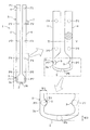
図7は、このようなセラミックヒーターが使用されたグロープラグ100の1例を示したものである。このグロープラグ100に使用されているセラミックヒーター101は、金属筒105内に内挿され、これを筒状の本体103の先端103aに固定して同本体103内に配置されている。同図のセラミックヒーター101は、先端で折り返し状(U字形状)をなす抵抗発熱体11を導電性セラミックからなるものとし、これを絶縁性セラミック(例えば窒化珪素)などの絶縁セラミック基体(支持体)93内に、側面に両端子17,18を露出させる形で埋設したものとされている。そして、一方の端子17は金属筒105に接続され、他方の端子18は中継線99を介してリード用軸部材107に接続され、この軸部材の後端寄り部位107cがガラス111や絶縁ブッシュ113を介して本体103に固定されている。このようなグロープラグ100では、リード用軸部材107に固定された端子部材109に電圧を印加し、電流を、同軸部材107、中継線99、セラミック抵抗発熱体11、及び金属筒105と流すことで、その抵抗発熱体11を発熱する構成とされている。
FIG. 7 shows an example of a
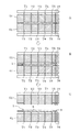
ところで、このようなグロープラグ100に使用されているヒーター101のうち、抵抗発熱体11の先端部分(同図下端部分)のみを局所的に急速加熱したいときにおいては、先端部分に位置するそのU字の折返し部分を含む部位を他の部位より小径線化する(横断面積を小さくする)ことが効果的である。図8は、そのような抵抗発熱体を形成するための焼成前の成形体(未焼成セラミック成形体)1の一例を示したものである。このものは、全体としてはU字形をなし、そのU字の折返し部2を含む先端寄り部位が小径線部3とされており、この小径線部3を除くU字の両脚部4が大径線部5とされている。一方、このような成形体1を、タングステンカーバイト(WC)或いは二珪化モリブデン(MoSi2)を含む導電性セラミックで形成する場合には射出成形によって製造するのが普通である。このような成形体1を射出成形によって製造する場合には、型合せ面(型閉じ面)に、成形体1に対応するU字形状のキャビティー(凹部)が形成された、上下一対の成形型(金型)が使用される。そして、このような成形体の製造においては、図9−Aに示したように、上下の成形型51,61を型閉じしてできるキャビティ内に成形体形成用の素材(生地)を射出し、固化後において、図9−B、図9−Cに示したように、型開きしてその成形体1を取り出すことになる。
By the way, in the
ところで、このような成形においては、成形体1を成形型(内面)51,61から円滑に分離(離型)して取り出すため、その成形型51,61には、適所に成形体1を突き出す突出しピン(円柱状の押し出しピン)T1〜T6が配置されたものが使用される。そして、型開きにおいては図9に示したように、突出しピンT1〜T6をキャビティー側に突き出し、成形体1をキャビティーの底面から若干浮かすことが行われる。このように成形体1をキャビティ内面から確実に分離させ、その取り出しを円滑に行うためには、突き出しピン(以下、単にピンとも言う)T1〜T6は、成形体1の全体に適度に分散して設ける必要があり、したがって、その大径線部5だけでなく小径線部3にも設ける必要がある。図8中に破線で示した円形部位P1〜P6は、成形時にピンT1〜T6の先端が当たる位置を示している。
上記したように、抵抗発熱体の先端部分を小径線化することがヒーターの発熱効率上から要請されているが、そのように小径線化するほど、同抵抗発熱体を形成するための成形体1における小径線部3では、その部位を突き出すための突き出しピンT6の太さも細くする必要がある。すなわち、小径線部3を細くするほど突き出しピンも細くする必要があるが、ピンは細くなるほど変形、破損(座屈や曲がり)を起こしやすい。こうしたピンの変形を防止するため、従来はピンの材質、強度にもよるが、一般的な超硬合金製のピンでは、その太さは直径で約1mm以上、最小でも0.8mm以上あることが要請されていた。このため、従来の成形体1の射出成形においては、その先端部分を小径線化するとしても、0.8mm程度が限界とされていた。したがって、成形体1の先端の小径線部3のうちの直線部3aを図8中の破線S1で示したように、例えば0.4mmと細くする場合には、成形体1における同直線部3aに対応する部位には突き出しピンT6を配置させることはできない。このような場合には、その先端部位には、例えば、U字の折返し部2の中央を図8に示したように太くしておくことで、その中央部位P6にピンT6を配置できるに止まる。
As described above, it is required from the viewpoint of the heat generation efficiency of the heater to reduce the diameter of the tip portion of the resistance heating element. However, as the diameter decreases, the molded body for forming the resistance heating element becomes smaller. In the small-
ところが、図10に示したように、このようなピンの配置とされた成形型51,61で成形体1を成形して型開きする場合には、その小径線部3が、例えば、同図10−Cに示したような段階で、型面と円滑に分離できずに屈曲や変形を生じたり、或いは、その根元などにクラックが発生するなどの問題が頻発していた。すなわち、従来においては、小径線部3の太さを0.4mmのように細くする場合には、製造歩留まりの著しい低下を余儀なくされていた。したがって、従来は、先端部分のみを効率的に急速加熱することのできる抵抗発熱体を効率よく製造することができないという問題があった。
However, as shown in FIG. 10, when the
本発明は、こうした点に鑑みてなされたもので、その目的は、セラミック抵抗発熱体形成用の成形体であって、成形体自身が大径線部と小径線部とを備えかつその成形体が射出成形によって製造されるものにおいて、その成形体の製造歩留まりの低下を招くことなく、その小径線部の太さを従来よりも格段と細くできるようにすることにある。 The present invention has been made in view of these points, and an object thereof is a molded body for forming a ceramic resistance heating element, the molded body itself having a large-diameter wire portion and a small-diameter wire portion, and the molded body. Is manufactured by injection molding so that the thickness of the small-diameter wire portion can be made much thinner than before without causing a decrease in the manufacturing yield of the molded body.
上記の目的を達成するために請求項1に記載の本発明は、セラミック抵抗発熱体形成用の成形体であって、成形体自身が大径線部と小径線部とを備えかつその成形体が射出成形によって製造されるものにおいて、
その成形体自身を射出成形後において成形型から突き出すための突き出しピンが、前記大径線部とともに前記小径線部を突き出し可能に、該小径線部の適所に凸部を設けたことを特徴とするセラミック抵抗発熱体形成用の成形体である。
In order to achieve the above object, the present invention according to
The projecting pin for projecting the molded body itself from the mold after injection molding is characterized in that a convex portion is provided at an appropriate position of the small diameter wire portion so that the small diameter wire portion can be projected together with the large diameter wire portion. This is a molded body for forming a ceramic resistance heating element.
請求項2に記載の本発明は、セラミック抵抗発熱体形成用の成形体であって、成形体自身がU字形をなし、そのU字の底部である先端の折返し部を含む両脚部の先端寄り部位が小径線部で、その小径線部を除く両脚部が大径線部をなし、かつその成形体が射出成形によって製造されるものにおいて、
その成形体自身を射出成形後において成形型から突き出すための突き出しピンが、前記大径線部とともに前記小径線部を突き出し可能に、該小径線部の適所に凸部を設けたことを特徴とするセラミック抵抗発熱体形成用の成形体である。
The present invention according to
The projecting pin for projecting the molded body itself from the mold after injection molding is characterized in that a convex portion is provided at an appropriate position of the small diameter wire portion so that the small diameter wire portion can be projected together with the large diameter wire portion. This is a molded body for forming a ceramic resistance heating element.
請求項3に記載の本発明は、前記凸部を、前記小径線部におけるU字の内側部位に設けたことを特徴とする請求項2に記載のセラミック抵抗発熱体形成用の成形体である。
The present invention according to
請求項4に記載の本発明は、前記成形体は、前記小径線部及び前記大径線部とも、同じ抵抗を有する素材からなることを特徴とする請求項1〜3のいずれか1項に記載のセラミック抵抗発熱体形成用の成形体である。 According to a fourth aspect of the present invention, in the molded product according to any one of the first to third aspects, the molded body is made of a material having the same resistance in both the small diameter wire portion and the large diameter wire portion. It is a molded object for ceramic resistance heating element formation of description.
請求項5に記載の本発明は、前記成形体は、前記小径線部を含む部位が高抵抗素材からなり、その他の部位が低抵抗素材からなる複合体としてなることを特徴とする請求項1〜3のいずれか1項に記載のセラミック抵抗発熱体形成用の成形体である。
The present invention described in
請求項6に記載の本発明は、請求項1〜5のいずれか1項に記載のセラミック抵抗発熱体形成用の成形体を絶縁セラミック基体中に埋設状にして焼成してなることを特徴とするセラミックヒーターである。 A sixth aspect of the present invention is characterized in that the ceramic resistance heating element forming molded body according to any one of the first to fifth aspects is embedded in an insulating ceramic substrate and fired. It is a ceramic heater.
本発明のセラミック抵抗発熱体形成用の成形体では、その成形体自身を射出成形後において成形型(金型)から突き出すための突き出しピン(以下、単にピンとも言う)が、前記大径線部とともに前記小径線部を突き出し可能に、該小径線部の適所に凸部を設けている。すなわち、このような凸部を設けた部位では、その分、単なる小径線部に比べて幅広となる。このため、小径線部自体が細くても、その成形時には、小径線部の部位も大径線部と同様に、強度のある太い突き出しピンにて突き出すことができる。これにより、従来よりも細い小径線部であっても折れや屈曲等のない成形体を製造歩留まりよく製造できる。 In the molded body for forming a ceramic resistance heating element according to the present invention, an ejection pin (hereinafter also simply referred to as a pin) for projecting the molded body itself from a mold (mold) after injection molding is the large-diameter wire portion. In addition, a convex portion is provided at an appropriate position of the small-diameter wire portion so that the small-diameter wire portion can be projected. That is, the portion provided with such a convex portion is wider than that of a simple small-diameter portion. For this reason, even if the small-diameter wire portion itself is thin, the portion of the small-diameter wire portion can be protruded by a strong and thick protruding pin in the same manner as the large-diameter wire portion. Thereby, even if it is a thin wire part thinner than before, a molded object which does not bend or bend can be manufactured with a high manufacturing yield.
このように、本発明によれば、先端又は先端寄り部位が小径線部で、その他が大径線部としてなる、ヒーター用の抵抗発熱体形成用の成形体を射出成形により製造する際において、その成形体の製造歩留まりの低下を招くことなく、その小径線部の太さを従来よりも格段と細くできるという顕著な効果が得られる。そして、その結果、このような本発明に係る成形体を絶縁セラミック基体中に埋設して同時焼成することで、昇温効率が高いセラミックヒーターを低コストで提供できる。 Thus, according to the present invention, the tip or the portion near the tip is a small-diameter wire portion, and the others are large-diameter wire portions, when manufacturing a molded body for forming a resistance heating element for a heater by injection molding. The remarkable effect that the thickness of the small diameter wire portion can be remarkably reduced as compared with the conventional one can be obtained without causing a decrease in the manufacturing yield of the molded body. As a result, a ceramic heater having high temperature rise efficiency can be provided at low cost by embedding such a molded body according to the present invention in an insulating ceramic substrate and simultaneously firing it.
本発明における前記凸部は、小径線部の適所の一部に設けることでよいが、請求項2に記載の形状の成形体においては、請求項3に記載の本発明のように、前記凸部を、前記U字の内側部位に設けるのがよい。というのは、成形体は絶縁セラミック基体内に埋設された状態で焼成されてヒーターをなし、その抵抗発熱体となる。一方、この絶縁セラミック基体は通常、同一太さ(例えば同直径の円柱状)に形成される。このため、その凸部がU字の外側にあると、その凸部の存在する部位における絶縁セラミック基体(絶縁材)の表面の肉厚が部分的に薄くなる。したがって、ヒーターの使用過程での絶縁材の摩耗により、抵抗発熱体が露出して外部に晒されて酸化してしまう危険性がある。これに対して、請求項3に記載のように、U字の内側に凸部が位置するようにすることで、そうした危険性を回避することができる。また、小径線部は、U字を正面からみて、同一太さでU字状に形成された成形体において、そのU字の折返し部を含む先端寄り部位の内側の肉を盗む(除去する)形とすることで形成できる。この場合には、その先端寄り部位の内側に盗んだ肉の分のスペースができるため、凸部を設けるのに適する。
The convex portion in the present invention may be provided at a part of the small diameter wire portion. However, in the molded body having the shape according to
また、本発明における成形体は、請求項4に記載のように、前記小径線部及び前記大径線部とも、同じ抵抗を有する素材から形成したものとすれば、簡易な工程でその製造ができる。しかし、請求項5に記載のように、成形体を、前記小径線部を含む部位が高抵抗素材からなり、その他の部位が低抵抗素材からなる複合体として形成してもよい。このような複合体として形成すれば、小径線部が同一太さでもより急速高温化が図られる。このため、この成形体を絶縁セラミック基体中に埋設状にして焼成してなるセラミックヒーターによれば、より優れた昇温特性のセラミックヒーターを得ることができる。なお、高抵抗素材からなる小径線部を含む部位と、その他の部位が低抵抗素材からなる複合体として形成してなる成形体において、その高抵抗素材と低抵抗素材との境界はセラミックヒーターの用途によって適宜に設定すればよい。
In addition, as described in
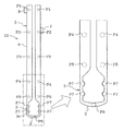
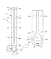
本発明の第1の実施の形態を図1〜図4に基いて詳細に説明する。図中1は、導電性セラミック(例えば、導電材料であるタングステンカーバイト(WC)と窒化珪素(Si3N4)との混合物)を主成分としてなる、セラミック抵抗発熱体形成用の成形体(未焼成の成形体)である。このものは、成形体1自身が概略U字形をなし、そのU字の底部である先端(図1下端)の折返し部2を含む両脚部の先端寄り部位が小径線部3で、その小径線部3を除く両脚部4が大径線部(太い棒状部)5をなしている。両脚部4をなす大径線部5は互いに平行に配置され、それぞれ直線状をなしており、横断面が同一で、例えば直径2mmの円断面(或いは楕円断面)とされている。ただし、大径線部5の各先端(図1下端)は、対向する内側においてテーパーをなして先端に向かうにしたがって先細り状に形成されている。なお、両脚部4は同一長さとされている。そして、その両脚部4の外側に向かって、図2に示したように(図1の側面視)例えば円形でかつ柱状の端子形成用のパッド部7,8が突出形成されている。なお、パッド部7,8は図1において上下方向において異なる高さに形成されている。本形態の成形体1は、図1においてこのパッド部7,8を除いて左右対称形とされ、図1の左右の側面も、図2に示したように対称形とされている。なお、図1中の各大径線部5に破線で付した円形部位P1〜P5は、詳しくは後述するが、この成形体1を射出成形した後、成形型から突き出すための突き出しピン(先端面)T1〜T5が当たる位置である。
A first embodiment of the present invention will be described in detail with reference to FIGS. In the figure,
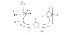
一方、小径線部3は、大径線部5の外側に沿って延びる直線部3aと、両直線部3aの先端を横向きに連結するU字の折返し部(横連結部)2とからなっている。そして、直線部3aは、次に説明する凸部9を除いて大径線部5より小さい直径の横断面円形(同一横断面)とされている。また、折返し部(横連結部)2は、その中央が先端向きに若干凸となす円弧状とされ、大径線部5より小さい直径で、しかも、本形態ではその中央部位が両直線部3aより太くなるように形成されている。このような小径線部3のなすU字の内側空間は大径線部5相互間に挟まれる内側空間よりも広く形成されている。
On the other hand, the small-
さて、このような本形態の成形体1では、小径線部3をなす左右の両直線部3aの中間部位のうち、U字の内側に位置する部位に、その内側に膨らむ形で半(1/2)円弧状の凸部9が膨出状に形成されている。この凸部9は、平面視(図1)においては半円形状を呈しているが、その厚さは小径線部3の直径と同様に設定されている。なお、小径線部3をなす両直線部3aの太さは、例えば0.56mmと細くされ、凸部9は図1においてその円弧の半径R1が0.4mmとされており、本形態では、凸部9のある部位における小径線部3の幅W1は0.9mmとされている。したがって、小径線部3のうち凸部9に対応する部位(図1中の破線の円形部位P7)には、直径0.8mmの円柱状のピンT7の先端面が当接できるように設定されている。なお、折返し部2の中央部位の幅W2は0.8mmとされており、そこに付された破線の円形部位P6には直径0.8mmの円柱状のピンT6の先端面が当接できるように設定されている。また、凸部9における半円形の平面と、その半円弧の周面との稜線部には角ができないように適度の小アールによる面取りが付けられている。
Now, in the molded
しかして、このような成形体1によれば、これを射出成形により製造する場合においては、従来と同様に、図2における中心線PLが型合わせ面となるように、それぞれの型合わせ面に成形体1に対応するU字形状で、凹設、形成されたキャビティを有する一対の成形型を用いることで、これを成形できる。この場合において、各成形型には、大径線部5を突き出すためのその各円形部位P1〜P5及び小径線部3のうちの折返し部2の中央の円形部位P6に加えて、小径線部3のうちの凸部9に対応する円形部位P7にも、突き出しピンの先端を配置させることができる。すなわち、小径線部3のうち、0.4mmとさらに細い両直線部3aにも、その凸部9に対応する部位P7に、強度を保持できる太さ(0.8mm)のピンを配置できる。
Thus, according to such a molded
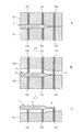
このため、図3−Aに示したように、このような成形型51,61を用いて成形体1を射出成形した後、図3−Bに示したように、上型51のピンT1〜T7を突出させたままで上型51を上昇して型開きし、その後、図3−Cに示したように、ピンT1〜T7とともに上型(図示せず)を上昇し、かつ下型61のピンT1〜T7を突出させることで、成形体1は型から分離されるが、その際には、小径線部3も他の部位と共に突き出される。なお、図3においては、T1〜T3はその図示を省略している。このため、成形体1の取り出しにおいてその小径線部3が折れたり曲がったり、或いはクラックが発生することもない。このように本発明によれば、小径線部3の太さを、配置すべきピンの太さよりも細くしても、その小径線部3の突き出しができるため、小径線部3の細い成形体1を効率よく製造できる。
For this reason, as shown in FIG. 3A, after the molded
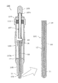
なお、図4は、このようにして形成された成形体1を、例えば円柱状をなす絶縁セラミック基体93中に埋設状にした状態を示している。しかして、その後、仮焼成等の所定の熱処理工程等を経た後で、ホットプレスにて焼成し、外周面を研磨したり、先端(下端)を半球面状に仕上げることで、セラミックヒーターとなる。このセラミックヒーターをなす絶縁セラミック基体93は、窒化珪素質などが例示される。なお、セラミックヒーターにおいては、図示したように端子パッド7,8は、側面にそれぞれ露出している。なお、成形体1は焼成後には抵抗発熱体となるが、その製造過程のプレスにより、横断面は変形したものとなる。
FIG. 4 shows a state in which the formed
また、このようなセラミックヒーターにおいては、その内部の成形体が焼成されてなる抵抗発熱体の凸部9が、U字の内側に位置する部位に設けられている。このため、同ヒーターの絶縁セラミック基体93の外部表面から抵抗発熱体(焼成前の成形体)までのその絶縁セラミック層の肉厚の部分的な減少もない。したがって、セラミックヒーターがグロープラグとして使用される場合のように、絶縁セラミック基体93の表面の摩耗があるような場合でも、セラミック抵抗発熱体が露出する危険性も防止できる。
Moreover, in such a ceramic heater, the
さて次に、上記の実施の形態のものにおいて、小径線部3に凸部9を設けたものと、設けない成形体の各サンプルを射出成形して成形型から取り出し、それぞれの小径線部にクラック等の欠点がないかを確認してみた。すなわち、前記実施の形態の小径線部3に凸部9を有する本発明品の成形体のサンプルと、凸部9がない比較例の成形体のサンプルとを製造した。本発明品では、上記したように小径線部3のうち、凸部9の部位P7が突き出しピンT7で突き出される構成の成形型によって成形したものであり、比較例サンプルでは、これに対応する位置に突き出しピンを配置していない成形型によって成形したものである。なお、本発明品及び比較例とも、小径線部3のうち、折返し部2の中央部位P6には突き出しピンT6を配置して製造した。各成形型はともに1面4個取りのものを用い、25ショットでそれぞれ100個づつ製造した。なお、欠点の確認は、成形後、200℃で50分間乾燥した後、拡大鏡で外観検査を実施して、欠点があるものを不良品としてカウントした。結果は表1に示した通りである。
Now, in the above-described embodiment, each sample of the molded body that is provided with the
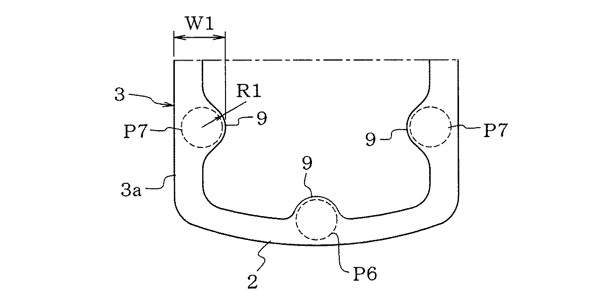
表1に示したように、小径線部3に凸部9のある本発明品では、サンプルのうち1個のものの小径線部3に欠点が見られ、99%の歩留まりであった。これに対して、小径線部3に凸部のない比較例では、30個のサンプルの小径線部3に欠点が見られ、70%の歩留まりであった。この結果は、とりもなおさず本発明の効果を実証するものである。
As shown in Table 1, in the product of the present invention having the
また、前記形態では、セラミック抵抗発熱体形成用の成形体1は、同じ抵抗を有する素材からなるものとしたが、上記もしたように、本発明の成形体1は、前記小径線部3を含む部位が高抵抗素材からなり、その他の部位が低抵抗素材からなる複合体としてもよい。例えば、図1の拡大図中のY−Y線より下を高抵抗素材で、上を低抵抗素材でそれぞれ形成する複合体としてもよい。このようにすれば、小径線部3の太さを前記形態のものと同じとしても、より高温に急速発熱させることができる。なお、このように成形体のうちの小径線部3を含む部位を高抵抗素材からなるものとするには、上記における導電材料であるタングステンカーバイトの比率を適宜に減らした素材でもって、小径線部3を含む部位を形成すればよい。
Moreover, in the said form, although the molded
因みに、このような複合体の成形体の射出成形は、上記の形状のもので、例示すれば次のようである。すなわち、成形体1のうちの大径線部5(成形体1)の部位(図1の拡大図のY−Y線より上の部位)を別途、低抵抗素材からなる生地で射出成形して形成しておく。そして、この大径線部の部分をなす成形体を、上記の形態で説明した成形型におけるキャビティのうち、その大径線部の形成用の部位にインサート(装填)して型閉じする。その後、成形型におけるキャビティのうち、残部(図1の拡大図のY−Y線より下の部位に相当する部位)に、高抵抗素材からなる生地を射出して、成形体として一体化する。このように一体化された成形体1の取出しにおいても、その小径線部3に形成された凸部9の位置に配置された突き出しピンT7により、その突き出しができるため、上記の形態と同様に、小径線部3にクラック等の欠点のない成形体1をうることができる。
Incidentally, the injection molding of such a composite molded body is of the above-described shape, and is exemplified as follows. That is, the part (the part above the YY line in the enlarged view of FIG. 1) of the large-diameter wire portion 5 (molded body 1) of the molded
もっとも、このような複合体の成形体は、前記した方法でなくとも製造できる。例えば、まず、上型を上記した上型(下型と同じもの)51のほか、例えば、型閉じしたとき、図1の拡大図のY−Y線より下の部位に相当するキャビティを無くする(占有する)ように形成された凸部を有する特殊上型を用いて型閉じする。この状態において存在するキャビティ(図1の拡大図のY−Y線より上の部位である大径線部5の形成用の部位)に、低抵抗素材からなる生地を射出する。そして、突き出しすることなく、その特殊上型を取り除き、上記した実施の形態に用いた上型51に代えて型閉じする。この後、成形型におけるキャビティのうち、残部(図1の拡大図のY−Y線より下の部位に相当する部位)に、高抵抗素材からなる生地を射出して、成形体1として一体化する。このようにして一体的に成形された複合体からなる成形体の取り出しにおいても、大径線部5と共に小径線部3をも上記したのと同様にして各ピンで突き出すことで、前記したように小径線部3にクラック等の欠点のない成形体をうることができる。もちろん、高抵抗素材からなる生地を先に射出することとしてもよい。
However, such a molded body of the composite can be manufactured without using the method described above. For example, first, in addition to the upper mold (the same as the lower mold) 51 described above, for example, when the mold is closed, the cavity corresponding to the portion below the YY line in the enlarged view of FIG. 1 is eliminated. The mold is closed using a special upper mold having a convex portion formed so as to be occupied. In this state, a cloth made of a low-resistance material is injected into a cavity (a portion for forming the large-
本発明は、上記した内容のものに限定されるものではなく、その要旨を逸脱しない範囲において、適宜に変更して具体化できる。例えば、小径線部3に設ける凸部9は、小径線部3の太さや長さに応じて、ピンによる突き出し時に折れ等のない円滑な突き出しができるようにすればよい。したがって、図5に示した成形体21のように、凸部9は、小径線部3をなす直線部3aの適所に複数箇所づつ設けてもよい。同図のものでは2箇所であるが、凹凸が連続する形で多数設けることもできる。なお、図5に示した成形体21は、図1の成形体1と、膨らみ部9を各直線部3aに2箇所設けた点が異なるだけのため、同一部位には同一の符号を付し、その説明を省略する。
The present invention is not limited to the contents described above, and can be embodied with appropriate modifications without departing from the spirit of the present invention. For example, the
加えて、上記においては折返し部2をその中央が次第に太くなるように形成した場合を例示したが、図6に示したように、この折返し部2をピンT6の径より小さい一定幅とし、その中央に凸部9を設け、その凸部9に対応する円形部位P6にピンを配置するようにすることもできる。
In addition, in the above, the case where the folded
また、凸部9の形態は、円弧状のものでなくともよい。さらに、凸部9を設ける小径線部3の太さは、成形体1の素材(抵抗、強度)にもよるが、凸部9とあわせることで、ピンで突き出し可能であり、その際において小径線部に折れ等が生じることなく円滑に離型できる太さであればよい。抵抗発熱体として所望とする抵抗、小径線部の長さとの関係で、さらには、凸部の数やピッチとの関係で適宜に設定すればよい。なお、本発明に係る成形体は、これに限定されるものではない。また、小径線部、大径線部の横断面も、射出成形後、型から取り出す際に支障がない各種の形状のものとして具体化できる。
Moreover, the form of the
さらに、本発明に係るセラミック抵抗発熱体形成用の成形体の素材としては、導電材料であるタングステンカーバイトと窒化珪素とを主成分とするもの、或いは、二珪化モリブデン(MoSi2)と窒化珪素とを主成分とするものが代表例として例示できるが、もちろんこれら以外の素材で射出成形する場合にも本発明は適用できる。すなわち、本発明では、導電性のあるセラミック抵抗発熱体形成用の成形体であって、成形体自身が大径線部と小径線部とを備えかつその成形体が射出成形によって製造されるものに広く適用できる。また、本発明の成形体は、グロープラグ用のセラミックヒーターに使用されるものだけでなく、このようなセラミック抵抗発熱体形成用の成形体を絶縁セラミック基体中に埋設して焼成してなる各種のセラミックヒーターに広く適用できる。 Further, as a material of the molded body for forming a ceramic resistance heating element according to the present invention, a material mainly composed of tungsten carbide and silicon nitride, which are conductive materials, or molybdenum disilicide (MoSi 2 ) and silicon nitride. As a representative example, the main component can be exemplified by the above. However, the present invention can also be applied to the case of injection molding using materials other than these. That is, in the present invention, a molded body for forming a conductive ceramic resistance heating element, wherein the molded body itself has a large-diameter wire portion and a small-diameter wire portion, and the molded body is manufactured by injection molding. Widely applicable to. Further, the molded body of the present invention is not only used for a ceramic heater for glow plugs, but also various types of molded ceramic resistance heating element forming bodies embedded in an insulating ceramic substrate and fired. Widely applicable to ceramic heaters.
1 セラミック抵抗発熱体形成用の成形体
2 成形体の先端の折返し部
3 小径線部
4 成形体の脚部
5 大径線部
9 凸部
51,61 成形型
T1〜T7 突き出しピン
DESCRIPTION OF
Claims (6)
その成形体自身を射出成形後において成形型から突き出すための突き出しピンが、前記大径線部とともに前記小径線部を突き出し可能に、該小径線部の適所に凸部を設けたことを特徴とするセラミック抵抗発熱体形成用の成形体。 In a molded body for forming a ceramic resistance heating element, the molded body itself includes a large diameter wire portion and a small diameter wire portion, and the molded body is manufactured by injection molding.
The projecting pin for projecting the molded body itself from the mold after injection molding is characterized in that a convex portion is provided at an appropriate position of the small diameter wire portion so that the small diameter wire portion can be projected together with the large diameter wire portion. A molded body for forming a ceramic resistance heating element.
その成形体自身を射出成形後において成形型から突き出すための突き出しピンが、前記大径線部とともに前記小径線部を突き出し可能に、該小径線部の適所に凸部を設けたことを特徴とするセラミック抵抗発熱体形成用の成形体。 A molded body for forming a ceramic resistance heating element, wherein the molded body itself has a U-shape, and the portions near the distal ends of both legs including the folded portion of the distal end that is the bottom of the U-shape are the small-diameter wire portions. In the case where both legs excluding the part form a large diameter wire part, and the molded body is manufactured by injection molding,
The projecting pin for projecting the molded body itself from the mold after injection molding is characterized in that a convex portion is provided at an appropriate position of the small diameter wire portion so that the small diameter wire portion can be projected together with the large diameter wire portion. A molded body for forming a ceramic resistance heating element.
Priority Applications (6)
| Application Number | Priority Date | Filing Date | Title |
|---|---|---|---|
| JP2004112721A JP4331041B2 (en) | 2004-04-07 | 2004-04-07 | Molded body for forming ceramic resistance heating element, method for producing the same, and ceramic heater |
| EP12196555.2A EP2570726B1 (en) | 2004-04-07 | 2005-04-06 | Ceramic heater, method of producing the same, and glow plug using this ceramic heater |
| PCT/JP2005/006788 WO2005098317A1 (en) | 2004-04-07 | 2005-04-06 | Ceramic heater and manufacturing method thereof, and glow plug using ceramic heater |
| US11/578,102 US7705273B2 (en) | 2004-04-07 | 2005-04-06 | Ceramic heater, method of producing the same, and glow plug using a ceramic heater |
| EP05728784.9A EP1734304B1 (en) | 2004-04-07 | 2005-04-06 | Ceramic heater and manufacturing method thereof, and glow plug using ceramic heater |
| CN2005800120479A CN1942709B (en) | 2004-04-07 | 2005-04-06 | Ceramic heater, manufacturing method thereof, and glow plug using ceramic heater |
Applications Claiming Priority (1)
| Application Number | Priority Date | Filing Date | Title |
|---|---|---|---|
| JP2004112721A JP4331041B2 (en) | 2004-04-07 | 2004-04-07 | Molded body for forming ceramic resistance heating element, method for producing the same, and ceramic heater |
Publications (2)
| Publication Number | Publication Date |
|---|---|
| JP2005299945A true JP2005299945A (en) | 2005-10-27 |
| JP4331041B2 JP4331041B2 (en) | 2009-09-16 |
Family
ID=35331695
Family Applications (1)
| Application Number | Title | Priority Date | Filing Date |
|---|---|---|---|
| JP2004112721A Expired - Lifetime JP4331041B2 (en) | 2004-04-07 | 2004-04-07 | Molded body for forming ceramic resistance heating element, method for producing the same, and ceramic heater |
Country Status (2)
| Country | Link |
|---|---|
| JP (1) | JP4331041B2 (en) |
| CN (1) | CN1942709B (en) |
Cited By (2)
| Publication number | Priority date | Publication date | Assignee | Title |
|---|---|---|---|---|
| KR20110075000A (en) * | 2008-10-28 | 2011-07-05 | 쿄세라 코포레이션 | Ceramic heater |
| JP2015103470A (en) * | 2013-11-27 | 2015-06-04 | 日本特殊陶業株式会社 | Ceramic heater and glow plug |
Families Citing this family (4)
| Publication number | Priority date | Publication date | Assignee | Title |
|---|---|---|---|---|
| US20100288747A1 (en) * | 2007-10-29 | 2010-11-18 | Kyocera Corporation | Ceramic heater and glow plug provided therewith |
| US20130284714A1 (en) * | 2010-10-27 | 2013-10-31 | Takeshi Okamura | Heater and glow plug provided with same |
| CN103781208B (en) * | 2012-10-17 | 2016-04-20 | 昆山渝榕电子有限公司 | The conductive structure of heater |
| CN104961448B (en) * | 2015-05-13 | 2017-01-11 | 谢海涛 | Buchner funnel ceramic material and preparation method thereof |
-
2004
- 2004-04-07 JP JP2004112721A patent/JP4331041B2/en not_active Expired - Lifetime
-
2005
- 2005-04-06 CN CN2005800120479A patent/CN1942709B/en not_active Expired - Fee Related
Cited By (4)
| Publication number | Priority date | Publication date | Assignee | Title |
|---|---|---|---|---|
| KR20110075000A (en) * | 2008-10-28 | 2011-07-05 | 쿄세라 코포레이션 | Ceramic heater |
| KR101598013B1 (en) * | 2008-10-28 | 2016-02-26 | 쿄세라 코포레이션 | Ceramic heater |
| US9288845B2 (en) | 2008-10-28 | 2016-03-15 | Kyocera Corporation | Ceramic heater |
| JP2015103470A (en) * | 2013-11-27 | 2015-06-04 | 日本特殊陶業株式会社 | Ceramic heater and glow plug |
Also Published As
| Publication number | Publication date |
|---|---|
| CN1942709B (en) | 2010-06-09 |
| CN1942709A (en) | 2007-04-04 |
| JP4331041B2 (en) | 2009-09-16 |
Similar Documents
| Publication | Publication Date | Title |
|---|---|---|
| KR101089678B1 (en) | Ceramic heater, and its mold | |
| JP5279447B2 (en) | Ceramic heater | |
| JP4331041B2 (en) | Molded body for forming ceramic resistance heating element, method for producing the same, and ceramic heater | |
| JP5377662B2 (en) | Ceramic heater | |
| JP5261369B2 (en) | Multilayer heating element | |
| JP2010210134A (en) | Ceramic heater and glow plug | |
| CZ20022187A3 (en) | Heating pencil | |
| JP5249356B2 (en) | Glow tube used for sheath type glow plug and method for manufacturing the glow tube | |
| JP3799195B2 (en) | Ceramic heater | |
| JP6370754B2 (en) | Ceramic heater and glow plug | |
| JP5643611B2 (en) | Manufacturing method of ceramic heater and glow plug | |
| JP2005510358A (en) | Long member with material uneven distribution | |
| JP4555641B2 (en) | Glow plug | |
| JP6620032B2 (en) | Method for manufacturing ceramic heater and method for manufacturing glow plug | |
| JP2018190663A (en) | Manufacturing method of ceramic heater and manufacturing method of glow plug | |
| JPH08199205A (en) | Powder compact of connecting rod made of Al sintered alloy | |
| JP2017195078A (en) | Ceramic heater and glow plug | |
| JP6071426B2 (en) | Manufacturing method of ceramic heater | |
| JP2008075823A (en) | Method of manufacturing sintered bearing | |
| JPH05177290A (en) | Forging method and forging die | |
| SK9242002A3 (en) | Pin heater | |
| JP2001121217A (en) | Core rod | |
| JPH07100621B2 (en) | Method for manufacturing β-alumina tube |
Legal Events
| Date | Code | Title | Description |
|---|---|---|---|
| A621 | Written request for application examination |
Free format text: JAPANESE INTERMEDIATE CODE: A621 Effective date: 20060901 |
|
| A131 | Notification of reasons for refusal |
Free format text: JAPANESE INTERMEDIATE CODE: A131 Effective date: 20090303 |
|
| A521 | Request for written amendment filed |
Free format text: JAPANESE INTERMEDIATE CODE: A523 Effective date: 20090430 |
|
| TRDD | Decision of grant or rejection written | ||
| A01 | Written decision to grant a patent or to grant a registration (utility model) |
Free format text: JAPANESE INTERMEDIATE CODE: A01 Effective date: 20090602 |
|
| A01 | Written decision to grant a patent or to grant a registration (utility model) |
Free format text: JAPANESE INTERMEDIATE CODE: A01 |
|
| A61 | First payment of annual fees (during grant procedure) |
Free format text: JAPANESE INTERMEDIATE CODE: A61 Effective date: 20090617 |
|
| R150 | Certificate of patent or registration of utility model |
Free format text: JAPANESE INTERMEDIATE CODE: R150 Ref document number: 4331041 Country of ref document: JP Free format text: JAPANESE INTERMEDIATE CODE: R150 |
|
| FPAY | Renewal fee payment (event date is renewal date of database) |
Free format text: PAYMENT UNTIL: 20120626 Year of fee payment: 3 |
|
| FPAY | Renewal fee payment (event date is renewal date of database) |
Free format text: PAYMENT UNTIL: 20120626 Year of fee payment: 3 |
|
| FPAY | Renewal fee payment (event date is renewal date of database) |
Free format text: PAYMENT UNTIL: 20120626 Year of fee payment: 3 |
|
| FPAY | Renewal fee payment (event date is renewal date of database) |
Free format text: PAYMENT UNTIL: 20130626 Year of fee payment: 4 |
|
| R250 | Receipt of annual fees |
Free format text: JAPANESE INTERMEDIATE CODE: R250 |
|
| FPAY | Renewal fee payment (event date is renewal date of database) |
Free format text: PAYMENT UNTIL: 20130626 Year of fee payment: 4 |
|
| R250 | Receipt of annual fees |
Free format text: JAPANESE INTERMEDIATE CODE: R250 |
|
| R250 | Receipt of annual fees |
Free format text: JAPANESE INTERMEDIATE CODE: R250 |
|
| R250 | Receipt of annual fees |
Free format text: JAPANESE INTERMEDIATE CODE: R250 |
|
| R250 | Receipt of annual fees |
Free format text: JAPANESE INTERMEDIATE CODE: R250 |
|
| R250 | Receipt of annual fees |
Free format text: JAPANESE INTERMEDIATE CODE: R250 |
|
| R250 | Receipt of annual fees |
Free format text: JAPANESE INTERMEDIATE CODE: R250 |
|
| R250 | Receipt of annual fees |
Free format text: JAPANESE INTERMEDIATE CODE: R250 |
|
| R250 | Receipt of annual fees |
Free format text: JAPANESE INTERMEDIATE CODE: R250 |
|
| R250 | Receipt of annual fees |
Free format text: JAPANESE INTERMEDIATE CODE: R250 |
|
| R250 | Receipt of annual fees |
Free format text: JAPANESE INTERMEDIATE CODE: R250 |
|
| S531 | Written request for registration of change of domicile |
Free format text: JAPANESE INTERMEDIATE CODE: R313531 |
|
| R350 | Written notification of registration of transfer |
Free format text: JAPANESE INTERMEDIATE CODE: R350 |
|
| R250 | Receipt of annual fees |
Free format text: JAPANESE INTERMEDIATE CODE: R250 |
|
| EXPY | Cancellation because of completion of term |