JP2005299944A - Snow cooling system - Google Patents
Snow cooling system Download PDFInfo
- Publication number
- JP2005299944A JP2005299944A JP2004112701A JP2004112701A JP2005299944A JP 2005299944 A JP2005299944 A JP 2005299944A JP 2004112701 A JP2004112701 A JP 2004112701A JP 2004112701 A JP2004112701 A JP 2004112701A JP 2005299944 A JP2005299944 A JP 2005299944A
- Authority
- JP
- Japan
- Prior art keywords
- snow
- heat exchange
- cold
- heat
- water
- Prior art date
- Legal status (The legal status is an assumption and is not a legal conclusion. Google has not performed a legal analysis and makes no representation as to the accuracy of the status listed.)
- Pending
Links
Images
Landscapes
- Other Air-Conditioning Systems (AREA)
Abstract
Description
本発明は、雪冷房システムに関するものであり、特に、冬季の降雪を集めて保存し、雪が融解する際の冷熱を利用して、夏季の冷房に用いる雪冷房システムに関するものである。 The present invention relates to a snow cooling system, and more particularly to a snow cooling system used for summer cooling by collecting and storing snowfall in winter and using cold heat when the snow melts.
従来から、建築物の室内温度を冷房及び暖房するための冷暖房機器として種々のものが知られ、特に空気調和装置(エアーコンディショニング装置:エアコン)がオフィス、工場、及び一般家庭の種々の場所で広範に利用されている。 2. Description of the Related Art Conventionally, various types of air-conditioning equipment for cooling and heating the indoor temperature of a building are known, and in particular, air conditioners (air conditioning devices: air conditioners) are widely used in various places in offices, factories, and general households. Has been used.
係るエアコンの原理は、1)液体が気体に変化する(蒸発)時に周囲の物体から熱を吸収する性質、及び2)気体が液体に変化する(凝縮)時に、周囲に熱を放出する性質を利用している。そして、フロンガスなどの冷媒を室内機(蒸発機)によって液体から気体へ変化させ、一方、室外機(凝縮機)で冷媒を気体から液体に変化させることにより、室内に冷気を供給し、室内温度を低下させることができる(冷房)。また、上述と反対の処理を行うことにより、室内機(凝縮機)で冷媒(熱媒)を気体から液体に変化させ、室外機(蒸発機)で液体から気体へ変化させることにより、室内に暖気を供給し、室内温度を上げることができる(暖房)。なお、冷房及び暖房の切換えは、弁の開閉操作によって簡易に行うことができる。 The principle of such an air conditioner is that 1) the property of absorbing heat from surrounding objects when the liquid changes to gas (evaporation), and 2) the property of releasing heat to the surroundings when the gas changes to liquid (condensation). We are using. Then, the refrigerant such as chlorofluorocarbon gas is changed from liquid to gas by the indoor unit (evaporator), while the refrigerant is changed from gas to liquid by the outdoor unit (condenser), thereby supplying cold air to the room, Can be reduced (cooling). Also, by performing the opposite process to the above, the refrigerant (heat medium) is changed from gas to liquid in the indoor unit (condenser), and the liquid is changed from liquid to gas in the outdoor unit (evaporator). Warm air can be supplied to raise the room temperature (heating). Note that switching between cooling and heating can be easily performed by opening and closing a valve.
ところで、日本では古来から天然の氷を切出し、夏季まで保存しておくための氷室と呼ばれる小屋が作られている。この氷室は、果実等を冷やしたり、食物を長期にわたって保存するための、いわば「自然の冷蔵庫」のようなものである。また、四季の変化の激しい日本では、北海道地方や東北地方などの寒冷地域では、冬季の間は積雪の状態が継続し、春になるまで雪が融けないところが多い。そして、この雪を利用して、上述の氷室の場合と同様に、食物等を保存することは古来から行われている。 By the way, in Japan, huts called ice chambers have been made to cut out natural ice from ancient times and store it until summer. This ice chamber is like a “natural refrigerator” for cooling fruits and storing food for a long time. In Japan, where the seasons change drastically, in cold regions such as the Hokkaido and Tohoku regions, the snowy state continues during the winter, and the snow does not melt until spring. And using this snow, food and the like have been preserved since ancient times as in the case of the above ice chamber.
一方、上述の寒冷地域は、冬季の間は積雪が継続し、氷点下を下回る外気温が続くものの、夏季には日中の最高気温が30℃を超えるような平野部とあまり変わらない気温が観測されることがある。そのため、係る寒冷地域においても建築物には、上述した電力で稼働するエアコンなどの冷房機器が設置されていた。ところで、雪は、春になると気温の上昇に伴って徐々に融け始め、雪解け水になる。このとき、固体の雪から液体の水への相転移(融解)が行われ、この際に周囲の熱を吸熱することが知られている。 On the other hand, in the cold regions mentioned above, snow continues during the winter and the outside air temperature below freezing continues, but in summer the temperature is not so different from the plain where the daytime maximum temperature exceeds 30 ° C. May be. For this reason, in such cold regions, cooling equipment such as an air conditioner that operates with the above-described electric power is installed in the building. By the way, snow begins to melt gradually in the spring as the temperature rises, and becomes snowmelt. At this time, it is known that a phase transition (melting) from solid snow to liquid water takes place, and at this time, the surrounding heat is absorbed.
そして、北海道などの一部の地域では、上述の雪の相転移の際に生じる熱を利用して冷房システムを構築するものが開発されている。この冷房システムは、冬季の間に積雪した雪を一カ所に集めて夏季まで保存する貯雪庫と、貯雪庫に貯められた雪が融解した融解水を貯める貯水槽と、貯水槽に貯められた融解水を汲上げる汲上げ用のポンプと、ポンプで汲上げた融解水を一次冷却水として利用し、二次側の循環水との間で熱交換をさせる熱交換器と、冷却された二次側の循環水を利用して冷気を供給する冷水クーラとから構成されている。これにより、自然の力によって生成された雪の融解水を利用して室内の冷房を行うことができる。なお、係る構成の冷房システムにおいて、貯雪庫内に滞留する冷気を用いて室内の冷房を行うより簡易な構成のものもある。 In some areas such as Hokkaido, a system for building a cooling system using heat generated during the above-described snow phase transition has been developed. This cooling system collects snow accumulated during the winter in one place and stores it until the summer, a storage tank that stores the melted water that melts the snow stored in the storage, and a melting tank that stores the melt. A pump for pumping water, a heat exchanger for exchanging heat with the circulating water on the secondary side using the melted water pumped by the pump as primary cooling water, and a cooled secondary It is comprised from the cold water cooler which supplies cold air using the circulating water of the side. Thereby, indoor cooling can be performed using the melted water of snow generated by natural force. In addition, in the cooling system having such a configuration, there is a simpler configuration that cools the room by using the cool air staying in the snow storage.
以上の従来技術は、公然に実施されているものであり、出願人は、この従来技術が記載された文献を、本願出願時においては特に知見していない。 The above prior art is publicly implemented, and the applicant does not particularly know the document describing the prior art at the time of filing this application.
しかしながら、上述したエアコンの場合、冷房効率を高めようとする場合、室内機及び室外機を大型化したり、或いはフロンガスなどの冷媒を相転移させる際に利用するモータの運転効率を上げる必要があった。これにより、エアコンの電力消費量が大幅に増加することとなった。特に、夏季などは、一般家庭や工場等での冷房機器による電力消費量が急騰し、電力会社では電力の供給を一部停止したり、或いは予め各一般家庭等に対して節電を呼びかけることもあった。特に、現在日本国内で発電されている電力は、大別すると水力、火力、及び原子力によって生成されており、なかでも火力発電の占める比率が大きかった。そのため、貴重な石油資源を大量に電力エネルギーのために消費することとになり、地球資源の保護及び省エネルギー化の点から、なるべく電力消費量を抑え、かつ効率的に冷房することが可能なクリーンな冷房システムの開発が期待されていた。 However, in the case of the above-described air conditioner, in order to increase the cooling efficiency, it is necessary to increase the operating efficiency of the motor used when the indoor unit or the outdoor unit is enlarged or the phase transition of the refrigerant such as chlorofluorocarbon gas is performed. . As a result, the power consumption of air conditioners has increased significantly. In particular, in summer, etc., the amount of power consumed by cooling equipment in ordinary households and factories has soared, and electric power companies can suspend part of the power supply or call for power savings to ordinary households in advance. there were. In particular, the electric power currently generated in Japan is generated roughly by hydropower, thermal power, and nuclear power, and the ratio of thermal power generation is particularly large. As a result, a large amount of valuable petroleum resources will be consumed for power energy. From the viewpoint of protecting the earth resources and saving energy, it is possible to reduce power consumption as much as possible and clean the air efficiently. Development of a simple cooling system was expected.
一方、上述した雪を利用した冷房システムでは、下記に述べる問題を生じることがあった。すなわち、係るシステムは、一度貯雪した雪を融解水にした上で、係る融解水を一次側の冷却水として熱交換器に送っていた。ここで、貯雪庫に貯雪された雪の中には、空気中のゴミ等の夾雑物が多く混じっていることがあり、必ずしもきれいなものではなかった。そのため、ポンプで汲上げる際に予め一次冷却水をフィルター等で十分に濾過する必要があった。さらに、これらの夾雑物によって配管や汲上げ用のポンプを詰まらせてしまうことがあった。そのため、ポンプの汲上げ効率が低下したり、或いは頻繁にメンテナンス等を行う必要に迫られていた。これにより、稼働後のメンテナンスコストが増大することが予想された。 On the other hand, the cooling system using snow described above may cause the following problems. In other words, such a system converts snow once stored into melted water, and then sends the melted water to the heat exchanger as primary-side cooling water. Here, the snow stored in the snow storage has a lot of dust and other impurities in the air, which is not always clean. Therefore, it is necessary to sufficiently filter the primary cooling water with a filter or the like in advance when pumping with a pump. Furthermore, these contaminants sometimes clog piping and pumping pumps. For this reason, the pumping efficiency of the pump is reduced, or frequent maintenance or the like is required. This was expected to increase maintenance costs after operation.
そこで、本発明は、上記実情に鑑み、雪の冷熱を利用して室内を冷房することができ、かつ故障の発生頻度やメンテナンスコストを抑制することが可能な雪冷房システムの提供を課題とするものである。 In view of the above circumstances, an object of the present invention is to provide a snow cooling system that can cool the room using the cold heat of snow and can suppress the occurrence frequency and maintenance cost of failures. Is.
上記の課題を解決するため、本発明の雪冷房システムは、「雪を貯める貯雪空間を有する貯雪槽と、前記貯雪槽の槽底部に設けられ、前記雪の冷熱を伝搬可能な冷熱伝搬部と、前記雪が融解した融解水を、前記貯雪槽の前記貯雪空間及び前記冷熱伝搬部の間の伝搬界面から所定深さに貯水し、前記冷熱を前記冷熱伝搬部に伝える貯水部と、前記冷熱伝搬部に埋設され、第一熱交換部及び前記第一交換部と連結し、建築物の室内に導出された第二熱交換部を有し、内部に前記冷熱伝搬部から伝搬した前記冷熱を媒介する冷媒体が充填され、前記冷媒体が循環可能な熱交換パイプと、前記熱交換パイプ内に充填された前記冷媒体を前記第一熱交換部及び前記第二熱交換部の間で循環させる冷媒体循環手段と、前記第二熱交換部と接続し、前記第二熱交換部内の前記冷媒体の熱交換作用を利用して、前記室内に冷気を供給する冷気供給手段と」を具備するものから主に構成されている。 In order to solve the above-described problems, the snow cooling system of the present invention includes a "snow storage tank having a snow storage space for storing snow, a cold heat propagation part provided at the bottom of the snow storage tank and capable of propagating the cold heat of the snow, and A water storage part for storing the melted water in which the snow has melted at a predetermined depth from a propagation interface between the snow storage space of the snow storage tank and the cold heat propagation part, and transferring the cold heat to the cold propagation part, and the cold propagation Embedded in the part, connected to the first heat exchanging part and the first exchanging part, having a second heat exchanging part led out to the interior of the building, and mediating the cold heat propagated from the cold heat propagation part inside A heat exchange pipe that is filled with a refrigerant body that can be circulated and the refrigerant body that is filled in the heat exchange pipe is circulated between the first heat exchange section and the second heat exchange section. Refrigerant circulation means, connected to the second heat exchange unit, the second Using heat exchange action of the cooling medium in the switching section, it is mainly composed of those having a "and cold air supply means for supplying cooling air to the chamber.
ここで、貯雪槽とは、冬季に降雪した雪を集め、雪の冷熱を利用した冷房を実施する夏季まで雪の状態(固体状態)で保存しておくためのものである。そのため、保存時に暖気が侵入したり、或いは貯雪槽の周囲の外気温の変動によって貯雪空間内の雪が融解しないような断熱対策が施される必要がある。一例を挙げると、貯雪槽の周壁をスタイロフォームやウレタンボードなどの断熱性材料で被覆することなどが行われている。さらに、雪の保存時は、貯雪空間内の空気と外気との流通がないように、貯雪空間を外気から完全に遮断した密閉状態にすることが求められる。なお、係る貯雪槽に雪を貯める際には、寒冷地域で一般に利用されている除雪車(ロータリー車)によって、貯雪槽の一部に設けられた開口部から雪を飛散させながら投入する方法などが用いられる。なお、貯雪槽にはなるべく多くの雪を貯雪するために、貯雪した雪に力を加えて圧雪した状態で充填されることが望ましい。これにより、雪の保存期間を延長させ、雪の冷熱を利用した冷房を夏季の間継続して行うことができるようになる。 Here, the snow storage tank is for collecting snow that has fallen in winter and storing it in a snowy state (solid state) until summer in which cooling is performed using the cold heat of the snow. For this reason, it is necessary to take heat insulation measures such that warm air enters during storage or the snow in the snow storage space does not melt due to fluctuations in the outside air temperature around the snow storage tank. For example, a peripheral wall of a snow storage tank is covered with a heat insulating material such as styrofoam or urethane board. Furthermore, when storing snow, it is required that the snow storage space be completely sealed from the outside air so that there is no circulation between the air and the outside air in the snow storage space. In addition, when storing snow in such a snow storage tank, a method of throwing in snow from an opening provided in a part of the snow storage tank by a snowplow (rotary car) generally used in cold regions, etc. Is used. In order to store as much snow as possible in the snow storage tank, it is desirable that the snow storage tank is filled in a state where pressure is applied to the stored snow. Thereby, the preservation | save period of snow is extended and it becomes possible to continue the cooling using the cold of snow during the summer.
一方、冷熱伝搬部とは、貯雪空間に貯められた雪の冷熱(主に雪が融解する際に生じる融解潜熱)を後述の熱交換パイプの第一熱交換部まで伝搬するものであり、冷熱伝搬部の伝搬の際に冷熱の損失が少ないように熱伝達係数の優れた材質で構成されることが望まれる。さらに、貯雪空間に圧雪した状態で充填された雪の重量に耐え、かつ内部に埋設された第一熱交換部に係る重量が加わらないように保護するために強固な素材で形成される必要がある。そのため、例えば、冷熱伝搬部は、貯雪槽の槽底部にコンクリートを流し込んで固めたコンクリート層によって形成したものを例示することができる。これにより、雪の冷熱を良好に第一熱交換部及び冷媒体に伝搬し、かつ雪の重量に対しても十分に耐える強度を提供することができる。なお、係るケースにおける冷熱伝搬部のコンクリートの層厚は、特に限定されないが、例えば、熱交換パイプのパイプ径等を考慮し、5cm以上、20cm以下、さらに好ましくは7cm以上、10cm以下に設定することができる。これにより、コンクリートによる冷熱伝搬部における熱損失を可能な限り抑え、かつ強度を保った状態で冷熱の伝搬が可能となる。 On the other hand, the cold heat propagation part propagates the cold heat of the snow stored in the snow storage space (mainly the latent heat of fusion that occurs when the snow melts) to the first heat exchange part of the heat exchange pipe described later. It is desired to be made of a material having an excellent heat transfer coefficient so that the loss of cold heat is small during the propagation of the part. Furthermore, it is necessary to be formed of a strong material to withstand the weight of the snow filled in the snow storage space in a state of snow pressure, and to protect the weight related to the first heat exchanging portion embedded therein from being added. is there. Therefore, for example, the cold heat propagation part can illustrate what was formed with the concrete layer which poured concrete into the tank bottom part of the snow storage tank, and was hardened. Thereby, the cold heat of snow can be favorably propagated to the first heat exchanging section and the refrigerant body, and strength sufficient to withstand the weight of snow can be provided. In addition, although the layer thickness of the concrete of the cold propagation | transmission part in such a case is not specifically limited, For example, considering the pipe diameter etc. of a heat exchange pipe, it sets to 5 cm or more and 20 cm or less, More preferably, it is set to 7 cm or more and 10 cm or less. be able to. Thereby, the heat loss in the cold heat propagation part made of concrete can be suppressed as much as possible, and the cold heat can be propagated while maintaining the strength.
また、貯水部は、貯雪空間内の雪が溶解して相転移した際に生じる融解水を伝搬界面から所定の深さに保って貯水するものである。ここで、貯雪空間の冷熱は、貯雪空間内の空気を媒介にして冷熱伝搬部に伝搬させることも可能であるが、一般に気体に比して液体が、圧倒的に熱伝達係数が大きいことが知られている。そこで、冷熱伝搬部及び貯雪空間の間の伝搬界面に融解水が当接するように、冷熱伝搬部及び貯雪空間の間に貯水部が形成される。その結果、雪の冷熱を効率的に冷熱伝搬部に伝えることが可能となり、冷熱伝搬部に伝わるまでの冷熱のエネルギー損失をより低く抑えることができる。 In addition, the water storage unit stores molten water generated when the snow in the snow storage space melts and undergoes phase transition while maintaining a predetermined depth from the propagation interface. Here, the cold heat in the snow storage space can be propagated to the cold heat propagation section through the air in the snow storage space, but generally the liquid has an overwhelmingly larger heat transfer coefficient than the gas. Are known. Therefore, a water storage portion is formed between the cold heat propagation portion and the snow storage space so that the molten water contacts the propagation interface between the cold heat propagation portion and the snow storage space. As a result, it is possible to efficiently transmit the cold heat of the snow to the cold heat propagation part, and it is possible to further reduce the energy loss of the cold heat until it is transmitted to the cold heat propagation part.
一方、熱交換パイプは、第一熱交換部が前述の冷熱伝搬部内に埋設された状態で設置され、さらに第一熱交換部と連結された第二熱交換部は、冷房対象となる建築物の室内まで導出されている。さらに、係る熱交換パイプ内には、第一熱交換部によって熱交換した雪の冷熱を媒介する冷媒体が充填されている。ここで、熱交換パイプの素材は、特に限定されないが、冷熱伝搬部または後述の冷気供給手段との熱交換作用を阻害することのない熱伝達係数の高い素材が好適である。しかしながら、設置に係るコスト及び強度等の点を勘案し、通常の水道用配管に利用される塩化ビニル樹脂、ステンレス製、及び亜鉛製など、或いはこれらの素材を複合的に形成された配管を利用することが好ましい。また、熱交換パイプに充填される冷媒体も特に限定されないが、氷点以下でも流動製を損なうことのないポリエチレングリコールなどを主成分とし、かつ熱保持性に優れる不凍液などを使用することが好ましい。雪冷房システムの設置条件によっては、上述した不凍液など以外にも、通常の水を冷媒体として利用することも可能である。これにより、雪冷房システムに要するコストの削減につながる。 On the other hand, the heat exchange pipe is installed in a state where the first heat exchange part is embedded in the aforementioned cold propagation part, and the second heat exchange part connected to the first heat exchange part is a building to be cooled. It is led out to the room. Further, the heat exchange pipe is filled with a refrigerant body that mediates the cold heat of the snow heat-exchanged by the first heat exchange section. Here, the material of the heat exchange pipe is not particularly limited, but a material having a high heat transfer coefficient that does not hinder the heat exchange action with the cold heat propagation section or the cold air supply means described below is suitable. However, taking into account the cost and strength of installation, etc., use polyvinyl chloride resin, stainless steel, zinc, etc., which are used for ordinary water supply pipes, or pipes formed by combining these materials It is preferable to do. Also, the refrigerant body filled in the heat exchange pipe is not particularly limited, but it is preferable to use an antifreeze liquid or the like that has polyethylene glycol or the like as a main component that does not impair fluidity even below the freezing point and has excellent heat retention. Depending on the installation conditions of the snow cooling system, it is also possible to use normal water as the refrigerant other than the above-described antifreeze. This leads to a reduction in costs required for the snow cooling system.
なお、冷熱伝搬部に埋設される第一熱交換部は、冷熱伝搬部を上述のコンクリート層によって形成する場合、熱伝搬層を破壊する必要があり、容易に交換することができない。そのため、特に内部を循環する冷媒体の漏出が生じないように、可能な限りジョイント数が少ない一体成形されたパイプを利用することが好適である。さらに、冷熱伝搬部に伝搬される雪の冷熱を十分に熱交換するために、第一熱交換部は、冷熱伝搬部との接触面積を大きく取る必要があり、冷熱伝搬部内を縦横配設されることがより好適である。一方、熱交換パイプ内に充填された冷媒体を第一熱交換部及び第二熱交換部の間で循環させる冷媒体循環手段は、周知の液体循環ポンプ等を利用することが可能であり、さらに冷気供給手段には、周知の冷房機器として知られるファンコイル(冷水クーラ)をそのまま応用することができる。 In addition, the 1st heat exchange part embed | buried under a cold-heat propagation part needs to destroy a heat-propagation layer, when a cold-heat propagation part is formed with the above-mentioned concrete layer, and cannot be replaced | exchanged easily. For this reason, it is preferable to use an integrally formed pipe with as few joints as possible so that the refrigerant circulating inside does not leak. Furthermore, in order to sufficiently exchange the cold heat of the snow propagated to the cold heat propagation portion, the first heat exchange portion needs to have a large contact area with the cold heat propagation portion, and the cold heat propagation portion is arranged vertically and horizontally. More preferably. On the other hand, the refrigerant body circulation means for circulating the refrigerant body filled in the heat exchange pipe between the first heat exchange part and the second heat exchange part can use a known liquid circulation pump, etc. Furthermore, a fan coil (cold water cooler) known as a known cooling device can be applied to the cold air supply means as it is.
したがって、本発明の雪冷房システムによれば、貯雪槽に貯雪した雪の冷熱が、貯水部の融解水、及び冷熱伝搬部を介して熱交換パイプの第一熱交換部まで伝搬される。そして、第一熱交換部内の冷媒体との間で熱交換が行われる。これにより、冷媒体の温度が低下する。一方、冷媒体は冷媒体循環手段によって第一熱交換部及び第二熱交換部の間を循環している。そのため、第一熱交換部で熱交換を行い、低い温度の冷媒体は循環によって建築物の室内に導出された第二熱交換部に到達する。そして、ここで、再び熱交換作用が行われる。このとき、第二第熱交換部と当接する空気は、冷媒体よりも暖かいものである。そのため、係る第二熱交換部の間では、冷媒体が暖かくなり、一方、第二熱交換部と当接した空気は冷たくなる。そして、冷たくなった空気(冷気)が建築物の室内に送出される。これにより、室内温度を低下させ、雪の冷熱を利用して建築物を冷房することができる。このとき、雪及び雪の融解水が冷媒と直に接することがなく、冷熱伝搬部を介して冷熱が伝搬される。また、融解水を直接ポンプで汲上げて循環させることがないため、雪(若しくは融解水)に含まれる夾雑物が配管内で詰まったり、ポンプの汲上げ効率を低下させることがない。さらに、貯雪空間及び冷熱伝搬部の間に融解水が貯水された貯水部が設けられているため、熱伝達係数の高い液体の水を介して雪の冷熱を伝えることができ、空気を媒介した場合と比して熱の伝達効率を向上させることができる。また、電力の消費は、冷媒体を循環させるポンプと、冷気供給手段として利用されるファンコイルの送風用のモータ等に抑えることができ、クリーンなエネルギーによる冷房システムを構築することができる。 Therefore, according to the snow cooling system of the present invention, the cold heat of the snow stored in the snow storage tank is propagated to the first heat exchange portion of the heat exchange pipe via the molten water of the water storage portion and the cold heat propagation portion. And heat exchange is performed between the refrigerant bodies in the first heat exchange section. Thereby, the temperature of a refrigerant body falls. On the other hand, the refrigerant body circulates between the first heat exchange part and the second heat exchange part by the refrigerant body circulation means. Therefore, heat exchange is performed in the first heat exchange section, and the low-temperature refrigerant body reaches the second heat exchange section led into the room of the building by circulation. And here, the heat exchange action is performed again. At this time, the air in contact with the second second heat exchange unit is warmer than the refrigerant. Therefore, between the said 2nd heat exchange parts, a refrigerant | coolant body becomes warm, on the other hand, the air which contact | abutted with the 2nd heat exchange part becomes cold. And the air (cold air) which became cold is sent out to the room | chamber interior of a building. Thereby, indoor temperature can be reduced and a building can be cooled using the cold of snow. At this time, the snow and the melted water of the snow are not in direct contact with the refrigerant, and the cold heat is propagated through the cold heat propagation portion. In addition, since melted water is not directly pumped up and circulated, impurities contained in snow (or melted water) are not clogged in the pipe, and pumping efficiency of the pump is not reduced. In addition, since a water storage part that stores molten water is provided between the snow storage space and the cold heat propagation part, it is possible to transmit the cold heat of the snow through liquid water with a high heat transfer coefficient, mediated air The heat transfer efficiency can be improved as compared with the case. Further, power consumption can be suppressed to a pump for circulating the refrigerant, a fan coil blowing motor used as a cold air supply means, and the like, and a cooling system using clean energy can be constructed.
さらに、本発明の雪冷房システムは、上記構成に加え、「前記貯雪槽は、前記貯水部によって貯められる前記融解水の上限位置に相当し、前記貯雪槽の槽壁を貫通して形成され、規定貯水量を越えた前記融解水を外部に排出する融解水排出部を」さらに具備するものであっても構わない。 Furthermore, the snow cooling system of the present invention has, in addition to the above-described configuration, “the snow storage tank corresponds to the upper limit position of the molten water stored by the water storage unit, and is formed through the tank wall of the snow storage tank, It may further comprise a “molten water discharge part for discharging the molten water exceeding the specified water storage amount to the outside”.
したがって、本発明の雪冷房システムによれば、貯雪槽の槽壁の一部に、融解水の上限位置に合わせて設定された融解水排出部が設けられている。ここで、貯雪空間内の雪は、時間の経過とともに徐々に水(融解水)に相転移し、貯水部に貯まり始める。そして、係る状態が継続されると次第に融解水の水量が増し、貯雪槽の大部分を融解水が占める事態が想定される。そこで、係る状態を回避する目的で、貯雪槽の槽壁に貫通して設けられ、融解水の一部を外部に排出する融解水排出部が設けられる。このとき、融解水排出部が貯水部に貯められた融解水の上限位置に設定されているため、係る上限位置以上に融解水が貯まった場合には、融解水排出部から速やかに排出されることになる。そのため、貯雪槽の槽底に設けられた貯水部には、常に一定の深さ(水量)の融解水が貯められていることになる。これにより、雪の冷熱を伝搬する伝搬効率を安定させることができる。なお、融解水排出部の設置位置は、特に限定されないが、例えば、貯雪空間及び冷熱伝搬部の間の伝搬界面から20cm以上、40cm以下、さらに好ましくは25cm以上、35cm以下に設定することが好適であり、係る範囲であれば融解水によって冷熱を冷熱伝搬部に伝搬する際の熱損失を少なくすることができる。 Therefore, according to the snow cooling system of the present invention, the molten water discharge part set in accordance with the upper limit position of the molten water is provided in a part of the tank wall of the snow storage tank. Here, the snow in the snow storage space gradually undergoes phase transition to water (melted water) with the passage of time and begins to accumulate in the water storage section. And if the state which concerns is continued, the amount of molten water will increase gradually, and the situation where molten water occupies most of a snow storage tank is assumed. Therefore, for the purpose of avoiding such a state, there is provided a molten water discharge portion that is provided through the wall of the snow storage tank and discharges a part of the molten water to the outside. At this time, since the molten water discharge part is set to the upper limit position of the molten water stored in the water storage part, when the molten water is stored above the upper limit position, it is quickly discharged from the molten water discharge part. It will be. For this reason, the water storage section provided at the bottom of the snow storage tank always stores molten water having a certain depth (water amount). Thereby, the propagation efficiency which propagates the cold heat of snow can be stabilized. In addition, although the installation position of a molten water discharge part is not specifically limited, For example, it is suitable to set to 20 cm or more and 40 cm or less from the propagation interface between a snow storage space and a cold-heat propagation part, More preferably, it is set to 25 cm or more and 35 cm or less. In such a range, it is possible to reduce heat loss when propagating cold heat to the cold propagation portion by the molten water.
さらに、本発明の雪冷房システムは、上記構成に加え、「前記融解水排出部に接続した排水管と、前記排水管の途中に設けられ、前記排水管を通じて前記貯雪空間に外気が侵入することを防ぐ外気侵入防止手段と」をさらに具備するものであっても構わない。 Furthermore, the snow cooling system of the present invention has the above-mentioned configuration, “a drain pipe connected to the molten water discharge section, and a midway of the drain pipe, and outside air enters the snow storage space through the drain pipe. It may further include an outside air intrusion preventing means for preventing
したがって、本発明の雪冷房システムによれば、融解水排出部に接続した排水管と、排水管の管中に設けられた外気侵入防止手段とを有している。ここで、前述したように貯雪空間内に保存された雪は、外気と完全に遮断した状態となっている。しかしながら、貯雪槽に貫設された融解水排出部は、必然的に外部と連通することとなり、係る融解水排出部を通じて暖かい外気が侵入する可能性が高い。これにより、雪の融解速度がより促進され、保存された雪が完全に融解水に相転移し、本発明の雪冷房システムを夏季の間継続して(例えば、9月の終わりごろまで)使用することができないことが想定される。そこで、融解水排出物の間に外気の侵入を防止する外気侵入防止手段が設けられている。なお、外気侵入防止手段の一例として、水道配管などで臭気防止等に利用されるS字形状のトラップを挙げることができる。係るトラップは、S字形状の一部に水を経常的に滞留させ、この水が外気の侵入を防ぐ蓋の機能を果たすものである。これにより、比較的簡易な構成で暖かい外気を防ぐことが可能となる。そのため、貯雪空間内の雪の融解の速度を促進させる要因を排除することができる。 Therefore, according to the snow cooling system of this invention, it has the drain pipe connected to the molten water discharge | emission part, and the external air intrusion prevention means provided in the pipe | tube of a drain pipe. Here, as described above, the snow stored in the snow storage space is completely blocked from the outside air. However, the molten water discharge part penetrating the snow storage tank inevitably communicates with the outside, and there is a high possibility that warm outside air will enter through the molten water discharge part. This further accelerates the melting rate of the snow, completely preserves the stored snow in the melted water, and continues to use the snow cooling system of the present invention during the summer (eg, until the end of September). It is assumed that it cannot be done. Therefore, outside air intrusion prevention means for preventing outside air from entering between the molten water discharges is provided. An example of the outside air intrusion prevention means is an S-shaped trap that is used to prevent odor in a water pipe or the like. Such traps function as a lid that causes water to stay in a part of the S-shape and prevents the intrusion of outside air. This makes it possible to prevent warm outside air with a relatively simple configuration. Therefore, it is possible to eliminate a factor that accelerates the melting speed of the snow in the snow storage space.
さらに、本発明の雪冷房システムは、上記構成に加え、「前記貯雪槽は、少なくとも一部が地表面下に埋設されている」ものであっても構わない。 Furthermore, the snow cooling system of the present invention may be one in which “the snow storage tank is at least partially embedded under the ground surface” in addition to the above configuration.
したがって、本発明の雪冷房システムによれば、雪を貯める貯雪槽の少なくとも一部が地表面から下に埋設されている。すなわち、地表面上は日中及び夜間の寒暖の差が激しい場合が多く、これに比べて地表面下は地表面温度の変化が一日であまりない。また、地表面よりも平均して温度が低くなることが知られている。そのため、貯雪槽の一部を埋設することにより外気温の変化による影響を貯雪空間内の雪が受けにくくなり、より良好な保存状態を保つことができる。すなわち、地表面下を自然の断熱層として利用することができる。また、建築物を新築する際には、係る貯雪槽を地下に設け、さらにその上に住居部を建築したものであってもよい。これにより、本発明の雪冷房システムを備えた建築物を省スペースで建築することができる。 Therefore, according to the snow cooling system of the present invention, at least a part of the snow storage tank for storing snow is buried below the ground surface. That is, there are many cases where the difference in temperature between daytime and nighttime is severe on the ground surface, and compared with this, there is not much change in the ground surface temperature under the ground surface in one day. It is also known that the temperature is lower on average than the ground surface. Therefore, by embedding a part of the snow storage tank, it is difficult for the snow in the snow storage space to be affected by changes in the outside air temperature, and a better preservation state can be maintained. That is, the underground surface can be used as a natural heat insulating layer. Moreover, when constructing a new building, such a snow storage tank may be provided in the basement, and a residential part may be further constructed thereon. Thereby, the building provided with the snow cooling system of the present invention can be constructed in a space-saving manner.
本発明の効果として、冬季の間に積雪した雪を集め、係る雪の冷熱を利用して夏季の室内の冷房を行うことができる。特に、雪の融けた融解水を直接ポンプなどで循環する必要がないため、雪に含まれる夾雑物による配管内の詰まりやポンプの故障などのトラブルを低く抑えることができる。これにより、メンテナンスコストを抑えた雪冷房システムを構築することができる。さらに、雪の融解した融解水を一定の深さに維持し、係る融解水及び冷熱伝搬部を介して冷熱を熱交換パイプに充填された冷媒体に安定して伝えることができる。これにより、熱交換時の熱損失を少なくし、雪の冷熱を効率的に冷房に利用することができる。さらに、融解水排出部に接続された排水管にもトラップ等の外気侵入防止手段が設けられているため、貯雪空間内の雪の融解速度を可能な限り低く抑えることができ、夏季の始期から終期まで継続して本発明の雪冷房システムを使用することができる。 As an effect of the present invention, it is possible to collect snow accumulated during the winter season and cool the indoors in the summer using the cold heat of the snow. In particular, since it is not necessary to circulate the melted water melted with snow directly with a pump or the like, troubles such as clogging in piping due to impurities contained in the snow and pump failure can be kept low. Thereby, it is possible to construct a snow cooling system with reduced maintenance costs. Furthermore, the melted water melted by snow can be maintained at a constant depth, and cold heat can be stably transmitted to the refrigerant body filled in the heat exchange pipe via the melted water and the cold heat propagation unit. Thereby, the heat loss at the time of heat exchange can be reduced, and the cold heat of snow can be utilized efficiently for cooling. Furthermore, since the drain pipe connected to the molten water discharge section is also provided with means to prevent outside air intrusion such as traps, the melting rate of snow in the snow storage space can be kept as low as possible. The snow cooling system of the present invention can be used continuously until the end.
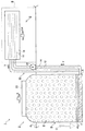
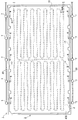
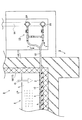
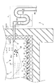
以下、本発明の一実施形態である雪冷房システム1について、図1乃至図4に基づいて説明する。ここで、図1は本実施形態の雪冷房システム1の概略構成を示す説明図であり、図2は第一熱交換部2の配設状態を模式的に示す説明図であり、図3は貯雪槽3、冷熱伝搬部5、及び第一熱交換部2の構成を示す説明図であり、図4は貯水部4、融解水排出部6、及び外気防止トラップ7の構成を示す説明図である。
Hereinafter, the
本実施形態の雪冷房システム1は、図1乃至図4に示すように、冬季の間に雪Sが降雪する寒冷地域に設置されるものであり、積雪した雪Sに貯雪することができる貯雪空間8を有し、夏季まで雪Sの状態で保存するための貯雪槽3と、貯雪槽3の槽底部9にコンクリートを流し込み、固化させることによって敷設され、雪Sの冷熱Cを伝搬可能な冷熱伝搬部5と、雪Sが融解して液体に相転移した融解水Lを、貯雪空間8及び冷熱伝搬部5の間の伝搬界面10から所定の深さに保って貯水し、雪Sの冷熱Cを融解水Lを介して冷熱伝搬部5に伝搬する機能を有する貯水部4と、冷熱伝搬部5との接触面積を最大限に大きくするために、冷熱伝搬部5内を縦横に亘って密集して埋設された第一熱交換部2、及び第一熱交換部2と接続し、冷房対象の建築物Bの室内Rに導出された第二熱交換部11を有し、内部にポリエチレングリコールの不凍液を主成分とする冷媒体12が循環可能に充填された熱交換パイプ13と、熱交換パイプ13の第一熱交換部2及び第二熱交換部11の間をそれぞれ連結する連結パイプ14に介設され、熱交換パイプ13内の冷媒体12をモータ(図示しない)の駆動によって循環させるための循環ポンプ15と、室内Rに導出された第二熱交換部11に取設され、第二熱交換部11との間で熱交換を行い、冷気CAを室内Rに送出する冷気送出装置16とを具備して主に構成されている。なお、冷気送出装置16は、既存の空調設備の一部(例えば、ファンコイルなど)を利用することが可能であり、詳細な説明は省略する。
As shown in FIGS. 1 to 4, the
さらに、詳しく説明すると、貯雪槽3は、貯雪空間8内の雪Sの保存状態を良好とするために、外殻18及び内殻19の二層構造によって形成されている。ここで、外殻18はコンクリートによって形成されており、貯雪槽3の基本骨格をなすものである。一方、内殻19は断熱性素材として利用されるスタイロフォームが外殻18の内表面に覆設されている。さらに、貯雪槽3は、伝搬界面10から約30cmの高さの位置に相当する槽壁17を貫通するようにして設けられた融解水排出部6が複数箇所に設けられている(図2参照)。この融解水排出部6は、貯水部4に規定水量以上の融解水Lが貯まった場合、貯水部4の上限位置LP(伝搬界面10から30cmの位置)を越えた融解水Lを速やかに外部に排出させるものであり、融解水排出部6の外殻18側には管状の排水管20が接続されている。さらに、図4に示すように、排水管20の途中には、暖かな暖気OAの侵入を防止するための外気防止トラップ7が介設されている。また、前述の融解水排出部6には、排水管20内に雪Sに含まれるゴミ等の夾雑物22が侵入し、管内を詰まらせることがないように、大きな夾雑物22を除去するためのメッシュ状のゴミ除去フィルター(図示しない)が設けられている。
More specifically, the
また、本実施形態の雪冷房システム1における冷熱伝搬部5は、内部に第一熱交換部2が埋設された状態で形成されている。係る冷熱伝搬部5は、そのため、予め貯雪槽3の槽底部9から僅かに上方に浮かせるようにして、冷熱伝搬部5との接触面積を大とするように、ほぼ槽底部9の底面を覆うように複数箇所を曲折して配設された第一熱交換部2(図2参照)に対し、コンクリートを流し込み、第一熱交換部2とともにコンクリートを固化させることによって形成されている。なお、本実施形態の雪冷房システム1においては、冷熱伝搬部5の層厚は約7cmに設定されている。
Moreover, the cold heat propagation |
さらに、貯雪槽3及びその下方に存在する冷熱伝搬部5及び第一熱交換部2は、いずれも地表面Gの下に埋設されている。そして、地表面Gから上には、貯雪空間8内に雪Sを投入するための雪投入口23を具備する貯雪槽3の一部と、第一熱交換部2から延設された一対の連結パイプ14とが突出している。なお、貯水部4から外部に排出された融解水Lは、前述の排水管20を通じて、地表面Gの下の既設の排水溝(図示しない)に流されている。したがって、貯雪槽3の上端付近が地表面Gの近傍に位置するため、貯雪槽3の貯雪空間8に雪Sを投入する際には、貯雪槽3の上端部に設けられた雪投入口23から除雪作業車等を利用して比較的簡易に行うことができる。加えて、貯雪槽3の大部分が地表面Gの下に埋設されているため、地表面Gの上に比べ、外気温の変化があまり大きくない。そのため、外気の影響を受けにくく、雪Sの保存状態を良好なものとすることができる。
Furthermore, the
次に、本実施形態の雪冷房システム1の使用の一例について説明する。始めに、冬季の間に積雪した雪Sを除雪作業車(図示しない)等を利用して、貯雪槽3の近傍に集め、さらに貯雪槽3の上端に設けられ、貯雪空間8に連通した雪投入口23から雪Sを投入する(図1における矢印X)。これにより、貯雪空間8に雪Sが大量に貯められる。なお、貯雪槽3の槽底部9は、コンクリートによって強固に固められた冷熱伝搬部5が形成されているため、投入された雪Sの重量に対して十分に耐え得る強度を有しており、内部に縦横無尽に埋設された第一熱交換部2に過大な負荷が加わることはない。さらに、このとき、投入直後の雪Sは、固体の状態を保持しているため、上述の貯水部4には融解水Lが貯水された状態になく、固体の雪Sが直接、冷熱伝搬部5の伝搬界面10に当接した状態にある。しかしながら、雪Sは内部に多量の空気(図示しない)を含んで構成されているため、伝搬界面10と雪Sとが完全に密着した状態にはなく、一部は雪Sの冷熱Cが空気(図示しない)を介して冷熱伝搬部5に伝搬されている。
Next, an example of use of the
そして、貯雪空間8内に雪Sを十分に圧縮した状態で充填が完了すると、雪投入口23が閉塞され、貯雪空間8を外気から完全に遮断した状態が創出される。その後、夏季の冷房を使用する時期が来るまで係る、外気との遮断状態を継続する。ここで、前述したように、貯雪槽3は、大部分が地表面Gの下に埋設されており、かつ二層構造によって断熱性に優れている。そのため、外気の変動による影響をそれほど受けることなく、冬季に貯雪された雪Sをほぼそのままの状態で夏季まで保たせることができる。すなわち、雪Sの個体状態を保持するために、全く電力等のエネルギーを必要としない。加えて、一日の間の外気温の変動が少ない地表面Gの下に大部分の貯雪槽3が埋設されているため、外気の影響が受けにくくなっている。そのため、雪Sの保存状態をさらに良好なものとすることができる。これにより、夏季の間に継続して室内を冷房することが可能な十分な量の雪Sが確保できる。
When the filling of the
しかしながら、貯雪槽3内の雪Sは少しずつではあるが徐々に融解している。そのため、固体の雪Sが融解して液体になった融解水Lは、重力に従って下方に向かって落下しながら流出する。その結果、最終的には、貯雪槽3の槽底部9に敷設された冷熱伝搬部5と貯雪空間8との間の伝搬界面10に到達する。そして、雪Sの融解が進み、多量の融解水Lが生成されると、前述した貯水部4に融解水Lが貯まり始める。その結果、雪S(貯雪空間8)及び冷熱伝搬部5の間に融解水Lによる層が形成される(図1参照)。なお、係る融解水Lからなる貯水部4は、前述したように貯雪槽3の槽壁17を貫通するようにして形成された融解水排出部6によって、予め設定した規定水量以上の融解水Lを外部に速やかに排出することができる。そのため、貯雪空間8内が融解水Lで満たされることがない。なお、融解水排出部6は、前述したように、伝搬界面10から30cmの高さに設けられており、そのため、貯水部4の融解水Lの上限位置LPも伝搬界面10から30cmとなっている。これにより、貯水部4は常に一定の水量を維持することができる。また、融解水排出部6から排出された融解水Lは、S字形状を呈する外気防止トラップ7のU字状のトラップ部(図示しない)に一端貯留される。そして、係るトラップ部に貯留された水量が規定水量を越えると、再び排水管20に導出され、外部に排出される。このとき、トラップ部に貯められた融解水Lによって排水管20と連通した外部から侵入する暖気OAが貯雪空間8に到達することを遮断することができる。その結果、雪Sの貯雪層3内での長期に亘る保存が可能となる。
However, the snow S in the
そして、夏季において冷房を開始する場合、循環ポンプ15及び冷気送出装置16を稼働状態にする。なお、循環ポンプ15等に接続して設けられた制御装置及び温度センサ(いずれも図示しない)を利用して、設定温度以上になると、循環ポンプ15及び冷気送出装置16を自動制御するものであってもよい。
Then, when cooling is started in summer, the circulation pump 15 and the cold
循環ポンプ15の稼働により、熱交換パイプ13の第一熱交換部2、連結パイプ14、及び第二熱交換部11の中に充填された冷媒体12が循環する(図1等における矢印Y参照)。このとき、第一熱交換部2では、貯雪空間8内の雪Sの冷熱Cが、貯水部4の融解水L、及び冷熱伝搬部5を介して冷媒体12に伝えられる。すなわち、冷媒体12を冷却するように熱交換が行われる。なお、第一熱交換部2は、図2に示したように冷熱伝搬部5内を縦横に曲折して配設されているため、温かい冷媒体12が第一熱交換部2の導入部24から導入され、第一熱交換部2内を流れる間に冷熱伝搬部5とほぼ同温度に冷却され、第一熱交換部2の導出部25に至る。そして、冷却された冷媒体12は、循環ポンプ15によって地表面Gの上方に向かって汲上げられ、第二熱交換部11まで送られる。これにより、雪Sの冷熱Cが建築物Bの室内Rにまで伝達されたことになる。その後、第二熱交換部11及び冷気送出装置16の間で再び熱交換が行われ、冷気CAが冷気送出装置16から送風される。一方、冷媒体12は熱交換によって再び温められ、連結パイプ14を介して再び第一熱交換部2の導入部24に送られる。そして、冷媒体12は、第一熱交換部2及び第二熱交換部11における熱交換を繰返し行う。
Due to the operation of the circulation pump 15, the
以上、説明したように、本実施形態の雪冷房システム1によれば、冬季の間に積雪した雪Sを貯雪槽3に一時的に保存し、夏季に係る雪Sの冷熱Cを利用して冷房に利用することができる。特に、雪Sの融解水Lを熱交換器に直接送ることなく、冷熱伝搬部5及び第一熱交換部2の間で熱交換させることができるため、融解水Lをポンプで直接汲み上げ、配管内を送出するものと比べ、雪Sに含まれる夾雑物22による影響を最小限に抑えることができる。さらに、気体よりも熱伝達係数の高い融解水Lを雪S(貯雪空間8)及び冷熱伝搬部4の間に配することにより、雪Sの冷熱Cに係るエネルギーを損なうことなく、効率的に第一熱交換部2にまで伝搬させることができる。加えて、貯雪槽3の大部分を地表面Gの下に埋設するため、外気の変動を受けにくく、夏季の終期まで本実施形態の雪冷房システム1を使用するための十分な量の雪Sを保存することができる。これにより、従来のエアコン等の冷房機器と比して、電力消費量を圧倒的に削減することができ、地球資源問題及び夏季における過剰な電力消費量に係る問題を解消することができる。
As described above, according to the
以上、本発明について好適な実施形態を挙げて説明したが、本発明はこれらの実施形態に限定されるものではなく、以下に示すように、本発明の要旨を逸脱しない範囲において、種々の改良及び設計の変更が可能である。 The present invention has been described with reference to preferred embodiments. However, the present invention is not limited to these embodiments, and various modifications can be made without departing from the spirit of the present invention as described below. And design changes are possible.
すなわち、本実施形態の雪冷房システム1において、図1に示したように、建築物B及び貯雪槽3を隣接させたものを示したが、これに限定されるものではなく、例えば、建築物の新築の際に、始めに貯雪槽3を地下に設け、その上に通常の住宅部分を設けたもの構成の雪冷房システムを構成することができる。これにより、従来と同規模の建築面積であっても、本発明の雪冷房システム1の効果を享受することができる。加えて、本実施形態の雪冷房システム1において、雪投入口23を貯雪槽3の上方に設けたものを示したが、これに限定されるものではなく、貯雪槽3の設置状況及び雪Sの投入状況に合わせて、貯雪槽3の側方などに設けるものであっても構わない。
That is, in the
1 雪冷房システム
2 第一熱交換部
3 貯雪槽
4 貯水部
5 冷熱伝搬部
6 融解水排出部
7 外気防止トラップ(外気侵入防止手段)
8 貯雪空間
9 槽底部
10 伝搬界面
11 第二熱交換部
12 冷媒体
13 熱交換パイプ
15 循環ポンプ(冷媒体循環手段)
16 冷気送出装置(冷気供給手段)
17 槽壁
20 排水管
B 建築物
C 冷熱
CA 冷気
G 地表面
L 融解水
R 室内
S 雪
DESCRIPTION OF
DESCRIPTION OF
16 Cold air delivery device (cold air supply means)
17
Claims (4)
前記貯雪槽の槽底部に設けられ、前記雪の冷熱を伝搬可能な冷熱伝搬部と、
前記雪が融解した融解水を、前記貯雪槽の前記貯雪空間及び前記冷熱伝搬部の間の伝搬界面から所定深さに貯水し、前記冷熱を前記冷熱伝搬部に伝える貯水部と、
前記冷熱伝搬部に埋設され、第一熱交換部及び前記第一交換部と連結し、建築物の室内に導出された第二熱交換部を有し、内部に前記冷熱伝搬部から伝搬した前記冷熱を媒介する冷媒体が充填され、前記冷媒体が循環可能な熱交換パイプと、
前記熱交換パイプ内に充填された前記冷媒体を前記第一熱交換部及び前記第二熱交換部の間で循環させる冷媒体循環手段と、
前記第二熱交換部と接続し、前記第二熱交換部内の前記冷媒体の熱交換作用を利用して、前記室内に冷気を供給する冷気供給手段と
を具備することを特徴とする雪冷房システム。 A snow storage tank having a snow storage space for storing snow;
A cold propagation part provided at the bottom of the snow storage tank and capable of propagating the cold of the snow;
Storing the melted water in which the snow is melted at a predetermined depth from a propagation interface between the snow storage space of the snow storage tank and the cold heat propagation part, and a water storage part for transmitting the cold heat to the cold heat propagation part;
Embedded in the cold heat propagation part, connected to the first heat exchange part and the first exchange part, having a second heat exchange part led out to the interior of the building, and propagated from the cold heat propagation part inside A heat exchanger pipe that is filled with a refrigerant body that mediates cold heat, and through which the refrigerant body can circulate;
Refrigerant body circulation means for circulating the refrigerant body filled in the heat exchange pipe between the first heat exchange section and the second heat exchange section;
A snow cooling system comprising: a cool air supply means that is connected to the second heat exchange section and supplies cool air into the room using a heat exchange action of the refrigerant body in the second heat exchange section. system.
前記貯水部によって貯められる前記融解水の上限位置に相当し、前記貯雪槽の槽壁を貫通して形成され、規定貯水量を越えた前記融解水を外部に排出する融解水排出部をさらに具備することを特徴とする請求項1に記載の雪冷房システム。 The snow storage tank
It further corresponds to the upper limit position of the molten water stored by the water storage section, and further includes a molten water discharge section that is formed through the wall of the snow storage tank and discharges the molten water that exceeds a specified water storage amount to the outside. The snow cooling system according to claim 1, wherein:
前記排水管の途中に設けられ、前記排水管を通じて前記貯雪空間に外気が侵入することを防ぐ外気侵入防止手段と
をさらに具備することを特徴とする請求項2に記載の雪冷房システム。 A drain pipe connected to the molten water discharge part;
The snow cooling system according to claim 2, further comprising an outside air intrusion prevention unit that is provided in the middle of the drain pipe and prevents outside air from entering the snow storage space through the drain pipe.
少なくとも一部が地表面下に埋設されていることを特徴とする請求項1乃至請求項3のいずれか一つに記載の雪冷房システム。 The snow storage tank
The snow cooling system according to any one of claims 1 to 3, wherein at least a part of the snow cooling system is embedded below the ground surface.
Priority Applications (1)
| Application Number | Priority Date | Filing Date | Title |
|---|---|---|---|
| JP2004112701A JP2005299944A (en) | 2004-04-07 | 2004-04-07 | Snow cooling system |
Applications Claiming Priority (1)
| Application Number | Priority Date | Filing Date | Title |
|---|---|---|---|
| JP2004112701A JP2005299944A (en) | 2004-04-07 | 2004-04-07 | Snow cooling system |
Publications (1)
| Publication Number | Publication Date |
|---|---|
| JP2005299944A true JP2005299944A (en) | 2005-10-27 |
Family
ID=35331694
Family Applications (1)
| Application Number | Title | Priority Date | Filing Date |
|---|---|---|---|
| JP2004112701A Pending JP2005299944A (en) | 2004-04-07 | 2004-04-07 | Snow cooling system |
Country Status (1)
| Country | Link |
|---|---|
| JP (1) | JP2005299944A (en) |
Cited By (4)
| Publication number | Priority date | Publication date | Assignee | Title |
|---|---|---|---|---|
| JP2010121854A (en) * | 2008-11-19 | 2010-06-03 | Tsuchiya Tokushu Nokigu Seisakusho:Kk | Device and method for cooling and refrigerating by artificial snow |
| JP2014044009A (en) * | 2012-08-27 | 2014-03-13 | Sekisui Kagaku Hokkaido Kk | Snow cold utilization facility |
| JP2017215062A (en) * | 2016-05-30 | 2017-12-07 | 株式会社土谷特殊農機具製作所 | Indirect heat exchange cold water circulation system |
| JP6460187B1 (en) * | 2017-09-05 | 2019-01-30 | 富士電機株式会社 | Snow and ice use air conditioning system, its snow and ice cooling system |
-
2004
- 2004-04-07 JP JP2004112701A patent/JP2005299944A/en active Pending
Cited By (5)
| Publication number | Priority date | Publication date | Assignee | Title |
|---|---|---|---|---|
| JP2010121854A (en) * | 2008-11-19 | 2010-06-03 | Tsuchiya Tokushu Nokigu Seisakusho:Kk | Device and method for cooling and refrigerating by artificial snow |
| JP2014044009A (en) * | 2012-08-27 | 2014-03-13 | Sekisui Kagaku Hokkaido Kk | Snow cold utilization facility |
| JP2017215062A (en) * | 2016-05-30 | 2017-12-07 | 株式会社土谷特殊農機具製作所 | Indirect heat exchange cold water circulation system |
| JP6460187B1 (en) * | 2017-09-05 | 2019-01-30 | 富士電機株式会社 | Snow and ice use air conditioning system, its snow and ice cooling system |
| JP2019045100A (en) * | 2017-09-05 | 2019-03-22 | 富士電機株式会社 | Air conditioning system using snow ice and snow ice cooler therefor |
Similar Documents
| Publication | Publication Date | Title |
|---|---|---|
| US5944089A (en) | Thermal storage systems for buildings | |
| US20070266722A1 (en) | In-ground geothermal heat pump system | |
| KR20090110904A (en) | Improved Design Architecture for Geothermal Direct Exchange Air Conditioning Systems | |
| JP2015511700A (en) | Heat pump system using latent heat | |
| US4656836A (en) | Pressurized, ice-storing chilled water system | |
| JP6524571B2 (en) | Control method of heat exchange device, heat exchange device, water-cooled heat pump cooling and heating device, water-cooled heat pump device | |
| JP2988905B2 (en) | Soil heat source ice heat storage heat pump device | |
| RU2234755C2 (en) | Plant for using power transformer excess heat | |
| JP2005299944A (en) | Snow cooling system | |
| US20070295489A1 (en) | Non-Intrusive and Extended Use of Water Reservoirs in Buildings as Thermal Storage for Heating, Ventilation and Air Conditioning Systems | |
| JP2007333295A (en) | Heat storage system | |
| JP2011247548A (en) | Snow air conditioning system | |
| CN110986653A (en) | Anti-freezing high-efficiency water chamber and heat exchanger | |
| JP5231353B2 (en) | Refrigeration system for snow and ice cooling | |
| JP2008164251A (en) | Snow cooling device | |
| KR101547875B1 (en) | Cooling-heating system by double pond | |
| JP2007093203A (en) | Waste heat recovery system | |
| KR200430990Y1 (en) | Heat pump type air conditioning system using underground geothermal heat | |
| JP2006029627A (en) | Terrestrial heat exchanging device | |
| US10962261B1 (en) | Earth coupled heat exchanger for a geothermal heat pump | |
| KR100793266B1 (en) | Economic air conditioning system using air heat heat pump | |
| JP2862946B2 (en) | Heat storage type air conditioning cooling method | |
| TWI734197B (en) | Multifunctional water storage circulation system for buildings | |
| William Fraser MSME | Mitigating Climate Change Impacts on Critical Infrastructure through Solar-Powered Thermosiphon Refrigeration Collars | |
| JP2004163002A (en) | Ice storage system |
Legal Events
| Date | Code | Title | Description |
|---|---|---|---|
| A977 | Report on retrieval |
Free format text: JAPANESE INTERMEDIATE CODE: A971007 Effective date: 20060810 |
|
| A131 | Notification of reasons for refusal |
Free format text: JAPANESE INTERMEDIATE CODE: A131 Effective date: 20060822 |
|
| A521 | Written amendment |
Effective date: 20061005 Free format text: JAPANESE INTERMEDIATE CODE: A523 |
|
| A02 | Decision of refusal |
Free format text: JAPANESE INTERMEDIATE CODE: A02 Effective date: 20061219 |