JP2005299941A - Cold transfer device - Google Patents
Cold transfer device Download PDFInfo
- Publication number
- JP2005299941A JP2005299941A JP2004112235A JP2004112235A JP2005299941A JP 2005299941 A JP2005299941 A JP 2005299941A JP 2004112235 A JP2004112235 A JP 2004112235A JP 2004112235 A JP2004112235 A JP 2004112235A JP 2005299941 A JP2005299941 A JP 2005299941A
- Authority
- JP
- Japan
- Prior art keywords
- working fluid
- unit
- cold
- evaporation
- amount
- Prior art date
- Legal status (The legal status is an assumption and is not a legal conclusion. Google has not performed a legal analysis and makes no representation as to the accuracy of the status listed.)
- Pending
Links
Images

Landscapes
- Devices That Are Associated With Refrigeration Equipment (AREA)
Description
本発明は、冷熱移送装置に関し、より詳細には、冷却装置の冷熱発生部で発生した冷熱を所定の冷却部位に移送するようにした冷熱移送装置に関する。 The present invention relates to a cold heat transfer device, and more particularly, to a cold heat transfer device configured to transfer cold heat generated in a cold heat generation unit of a cooling device to a predetermined cooling site.
従来、冷却装置の冷熱発生部で発生した冷熱を所定の冷却部位に移送するようにした冷熱移送装置としては、ヒートパイプの一種であるループ型サーモサイフォンのように、凝縮部と、蒸発部と、液体ラインと、蒸気ラインとからなる装置本体に作動流体を封入し、該作動流体を相変化させながら重力差を利用して循環させるものが知られている。 Conventionally, as a cold heat transfer device that transfers cold generated in a cold heat generation unit of a cooling device to a predetermined cooling site, a condensing unit, an evaporation unit, and a loop type thermosyphon that is a kind of heat pipe It is known that a working fluid is sealed in an apparatus main body composed of a liquid line and a vapor line, and the working fluid is circulated using a difference in gravity while changing the phase.
凝縮部は、冷却装置の冷熱発生部に熱的に接続されている。この凝縮部では、冷熱発生部で発生した冷熱により、内部を流れる作動流体が凝縮することになる。 The condensing part is thermally connected to the cold heat generating part of the cooling device. In this condensing unit, the working fluid flowing inside is condensed by the cold heat generated in the cold heat generating unit.
蒸発部52は、所定の冷却部位に配設されており、図5に示したように、下方から上方に向かって蛇行する態様で形成された作動流体の流路521と、該流路521の外部に形成された熱交換用フィン522とを備えて構成されている。この蒸発部52では、熱交換用フィン522を介して外気から得た熱により流路521を流れる作動流体が蒸発(気化)することになる。換言すると、蒸発部52の周辺領域(所定の冷却部位)の雰囲気は、作動流体が蒸発することによって熱が奪われることになり、冷却されることになる。
As shown in FIG. 5, the
液体ラインは、凝縮部で凝縮した作動流体を蒸発部52へ移動させるためのものである。蒸気ラインは、蒸発部52で蒸発した作動流体を凝縮部へ移動させるためのものである。
The liquid line is for moving the working fluid condensed in the condensing unit to the evaporating
上記冷熱移送装置では、上述のように重力差を利用して作動流体を循環させるものであるため、凝縮部を蒸発部52よりも上方側に配置して凝縮部と蒸発部52との液面の高低差を確保して装置本体を構成している。
In the cold transfer device, as described above, the working fluid is circulated using the difference in gravity, so that the condensing unit is disposed above the
しかしながら、上記冷熱移送装置では、装置本体に封入された作動流体の量(封入量)が蒸発部52における熱負荷に対して少ない場合には、凝縮部で凝縮され、液体ラインを通って流路521の入口521aより蒸発部52に流入した作動流体は、完全な液状態になっていないことがある。つまり、作動流体は、気液二相状態になっていることがある。このような状態の作動流体を蒸発部52に流入させてしまうと、該蒸発部52の最下層を流れる段階、すなわち流路521の一段目を流れる段階で、熱交換用フィン522を介して熱交換が行われて該作動流体は蒸発することになる。
However, in the above-described cold transfer device, when the amount of the working fluid enclosed in the apparatus main body (encapsulated amount) is small relative to the heat load in the
このように蒸発部52の最下層で作動流体が蒸発すると、蒸発した作動流体は上方にある流路521の出口521bに向かって該流路521を流れようとするが、該流路521には既に蒸発した作動流体の存在により出口521bへ流れる際の摩擦抵抗が大きくなっているために、蒸発した作動流体の一部が液体ラインを通って凝縮部に向かって逆流してしまうことがあった。
As described above, when the working fluid evaporates in the lowermost layer of the
逆流した作動流体は、凝縮部で凝縮された作動流体と熱交換して再び凝縮して蒸発部52に流れ、上述の動作を繰り返すことになり、結果的に、作動流体が装置本体をスムーズに循環しなくなってしまう。このように作動流体が装置本体をスムーズに循環しなければ、効率的に冷熱を移送することができず、その結果、冷却装置の冷却効率を低下させてしまうことになる。
The back-flowing working fluid exchanges heat with the working fluid condensed in the condensing unit, condenses again and flows to the
そこで、蒸発部の入口の上流側における液体ラインの所定の個所に、作動流体の逆流を阻止するためのトラップを設けた冷熱移送装置が提案されている(例えば、特許文献1)。 In view of this, a cold transfer device has been proposed in which a trap for preventing the backflow of the working fluid is provided at a predetermined location on the liquid line upstream of the inlet of the evaporation section (for example, Patent Document 1).
ところが、上記特許文献1に提案されている冷熱移送装置では、トラップを乗り越えて作動流体を循環させる必要があるために、作動流体を循環させるために必要なエネルギーの増大、例えば、凝縮部と蒸発部との液面の高低差を拡大させなければならない。換言すると、作動流体を循環させるために必要なエネルギーを増大させなければ、トラップで作動流体を循環させるためのエネルギーの一部が損失してしまい、結果として作動流体がスムーズに循環しなくなってしまう虞れがある。このように作動流体がスムーズに循環しなくなると、効率的に冷熱を移送することが困難になり、その結果、冷却装置の冷却効率を向上させることが困難になってしまう。また、上記特許文献1に提案されている冷熱移送装置では、トラップを作成するための特殊な加工が必要になってしまい、これにより装置全体に要するコストを増大させてしまう。 However, in the cold heat transfer device proposed in Patent Document 1, since it is necessary to circulate the working fluid over the trap, an increase in energy necessary to circulate the working fluid, for example, a condensing unit and evaporation The level difference of the liquid level with the part must be enlarged. In other words, unless the energy required for circulating the working fluid is increased, a part of the energy for circulating the working fluid in the trap is lost, and as a result, the working fluid does not circulate smoothly. There is a fear. If the working fluid does not circulate smoothly in this way, it becomes difficult to efficiently transfer the cold heat, and as a result, it becomes difficult to improve the cooling efficiency of the cooling device. In addition, the cold transfer device proposed in Patent Document 1 requires special processing for creating a trap, which increases the cost required for the entire device.
本発明は、上記実情に鑑みて、装置全体に要するコストを増大させないで、効率的に冷熱を移送させて冷却装置の冷却効率を向上させることができる冷熱移送装置を提供することを目的とする。 In view of the above circumstances, an object of the present invention is to provide a cold transfer device that can efficiently transfer cold and improve the cooling efficiency of the cooling device without increasing the cost required for the entire device. .
上記目的を達成するために、本発明の請求項1に係る冷熱移送装置は、冷却装置の冷熱発生部に熱的に接続させた凝縮部と、所定の冷却部位に配設した蒸発部と、前記凝縮部で凝縮させた作動流体を前記蒸発部まで移動させるための液体ラインと、前記蒸発部で蒸発させた作動流体を前記凝縮部まで移動させるための蒸気ラインとを有して成る装置本体を備え、前記装置本体に封入した作動流体を相変化させながら循環させて、前記冷熱発生部で発生した冷熱を所定の冷却部位に移送するようにした冷熱移送装置において、前記作動流体の封入量を調整して、前記蒸発部の最下層における作動流体を過冷却状態にする封入量調整手段を備えたことを特徴とする。 In order to achieve the above object, a cold heat transfer device according to claim 1 of the present invention includes a condensing unit thermally connected to a cold heat generating unit of the cooling device, an evaporation unit disposed at a predetermined cooling site, An apparatus main body having a liquid line for moving the working fluid condensed in the condensing unit to the evaporation unit and a vapor line for moving the working fluid evaporated in the evaporating unit to the condensing unit A cooling heat transfer device that circulates the working fluid sealed in the device main body while changing the phase thereof, and transfers the cold generated in the cold heat generating unit to a predetermined cooling site. And a sealing amount adjusting means for bringing the working fluid in the lowermost layer of the evaporation section into a supercooled state.
また、本発明の請求項2に係る冷熱移送装置は、スターリング冷凍機の冷却端部に熱的に接続させた凝縮部と、所定の冷却部位に配設した蒸発部と、前記凝縮部で凝縮させた作動流体を前記蒸発部まで移動させるための液体ラインと、前記蒸発部で蒸発させた作動流体を前記凝縮部まで移動させるための蒸気ラインとを有して成る装置本体を備え、前記装置本体に封入した作動流体を相変化させながら循環させて、前記冷却端部で発生した冷熱を所定の冷却部位に移送するようにした冷熱移送装置において、前記作動流体の封入量を調整して、前記蒸発部の最下層における作動流体を過冷却状態にする封入量調整手段を備えたことを特徴とする。 In addition, the cold heat transfer device according to claim 2 of the present invention includes a condensing unit thermally connected to a cooling end of a Stirling refrigerator, an evaporating unit disposed at a predetermined cooling site, and condensation in the condensing unit. An apparatus main body comprising a liquid line for moving the working fluid to the evaporation unit and a vapor line for moving the working fluid evaporated in the evaporation unit to the condensation unit, In the cold heat transfer device that circulates the working fluid sealed in the main body while changing the phase, and transfers the cold generated at the cooling end to a predetermined cooling site, the amount of the working fluid sealed is adjusted, It is characterized in that it is provided with a sealing amount adjusting means for bringing the working fluid in the lowermost layer of the evaporation section into a supercooled state.
また、本発明の請求項3に係る冷熱移送装置は、上記請求項1または上記請求項2において、前記封入量調整手段は、前記蒸発部の最下層における作動流体の温度に基づき前記作動流体の封入量を調整することを特徴とする。 According to a third aspect of the present invention, there is provided the cold heat transfer device according to the first or second aspect, wherein the enclosed amount adjusting means is configured to control the working fluid based on a temperature of the working fluid in a lowermost layer of the evaporation unit. The amount of sealing is adjusted.
本発明の冷熱移送装置によれば、封入量調整手段が、作動流体の封入量を調整して、蒸発部の最下層における作動流体を過冷却状態にするので、蒸発部の最下層で作動流体が蒸発する虞れがない。そのため、蒸発部で蒸発した作動流体が逆流してしまうことがなく、作動流体をスムーズに循環させることができ、これにより、効率的に冷熱発生部で発生した冷熱を移送することができ、冷却装置の冷却効率を向上させることができる。また、従来のように特殊な加工を施す必要がないので、装置全体に要するコストが増大する虞れがないという効果を奏する。 According to the cold heat transfer device of the present invention, the enclosing amount adjusting means adjusts the enclosing amount of the working fluid so that the working fluid in the lowermost layer of the evaporation unit is in a supercooled state. There is no risk of evaporation. Therefore, the working fluid evaporated in the evaporation section does not flow backward, and the working fluid can be circulated smoothly, whereby the cold heat generated in the cold heat generation section can be transferred efficiently, The cooling efficiency of the apparatus can be improved. In addition, since it is not necessary to perform special processing as in the prior art, there is an effect that the cost required for the entire apparatus does not increase.
以下に添付図面を参照して、本発明に係る冷熱移送装置の好適な実施の形態について詳細に説明する。 Exemplary embodiments of a cold transfer device according to the present invention will be described below in detail with reference to the accompanying drawings.
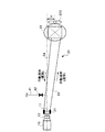
図1は、本発明の実施の形態に係る冷熱移送装置を示した概念図である。以下において、本実施の形態に係る冷熱移送装置は、自動販売機に適用されたスターリング冷凍機(冷却装置)で発生した冷熱を移送するものとして説明する。ここで、スターリング冷凍機について簡単に説明する。 FIG. 1 is a conceptual diagram showing a cold heat transfer device according to an embodiment of the present invention. In the following, the cold heat transfer device according to the present embodiment will be described as transferring cold heat generated by a Stirling refrigerator (cooling device) applied to a vending machine. Here, the Stirling refrigerator will be briefly described.
スターリング冷凍機10は、外部に圧縮機や凝縮器等を備えていない自己冷却型の冷凍機であり、内部の作動ガスを往復圧縮機で圧縮、膨張させることで、冷熱を発生する円筒状の冷却端部(冷熱発生部)11と、高熱を発生する円筒状の放熱端部12とを有している。作動ガスとしては、ヘリウムガス等が用いられており、フロン系ガスを用いないので、スターリング冷凍機10は地球環境に優しいものとして注目されている。このようなスターリング冷凍機10は、自動販売機の下部にある機械室等に載置してある。
The Stirling
図1において、冷熱移送装置は、装置本体20と、封入量調整ユニット(封入量調整手段)30とを備えて構成してある。装置本体20は、内部に作動流体が封入してあり、凝縮部21と、蒸発部22と、液体ライン23と、蒸気ライン24とを備えて構成してある。ここに、作動流体としては、例えば二酸化炭素等のように常温では気体であって、スターリング冷凍機10の冷却端部11で発生した冷熱では凍らない不凍冷媒が用いられている。
In FIG. 1, the cold heat transfer apparatus includes an apparatus
凝縮部21は、スターリング冷凍機10の冷却端部11に熱的に接続してある。より詳細に説明すると、凝縮部21は、スターリング冷凍機10の冷却端部11の周面を覆う態様で配設してある。この凝縮部21では、冷却端部11で発生した冷熱により内部を流れる作動流体が凝縮することになる。
The condensing
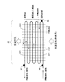
蒸発部22は、所定の冷却部位、例えば自動販売機の商品を収容する収容庫の下部等に配設してある。より詳細に説明すると、蒸発部22は、図2に示したように、下方の入口221aから上方の出口221bに向かって蛇行した態様で形成された作動流体の流路221と、該流路221の外部に形成された熱交換用フィン222とを備えて構成してある。この蒸発部22では、熱交換用フィン222を介して外気から得た熱により流路221を流れる作動流体が蒸発(気化)することになる。換言すると、蒸発部22の周辺領域の雰囲気は、作動流体が蒸発することにより熱が奪われることになり、冷却される。そして、ファン223を利用して冷却された雰囲気(以下、冷気ともいう)を被冷却物に送り込むことにより、被冷却物が冷却されることになる。
The
液体ライン23は、凝縮部21と蒸発部22とを繋ぐものである。この液体ライン23は、凝縮部21で凝縮された作動流体を該凝縮部21から蒸発部22まで移動させるためのものである。蒸気ライン24は、上記液体ライン23とは別個に、凝縮部21と蒸発部22とを繋ぐものである。この蒸気ライン24は、蒸発部22で蒸発した作動流体を該蒸発部22から凝縮部21まで移動させるためのものである。
The
凝縮部21と蒸発部22との配置関係は、凝縮部21が蒸発部22よりも上方に位置するようになっている。これは、凝縮部21と蒸発部22との液面の高低差Hを確保するためである。また、液体ライン23と蒸気ライン24との配置関係は、蒸気ライン24が液体ライン23の上方に位置するようになっている。これは、蒸気ライン24を流れる作動流体の密度の方が、液体ライン23を流れる作動流体の密度よりも小さいためである。
The arrangement relationship between the
封入量調整ユニット30は、装置本体20への作動流体の封入量を調整するものである。より詳細に説明すると、封入量調整ユニット30は、作動流体供給配管41を通じて装置本体20へ封入する作動流体の封入量を調整するものである。この封入量調整ユニット30は、図3に示したように、主制御部31と、温度検出部32と、バルブ制御部33とを備えて構成してある。
The enclosed amount adjusting unit 30 is for adjusting the amount of working fluid enclosed in the apparatus
主制御部31は、例えばROMやRAM等のメモリ34に格納されたプログラムやデータに基づいて封入量調整ユニット30の動作を統括的に制御するものである。温度検出部32は、蒸発部22の複数の個所に取り付けた温度センサ35,36,37を通じてそれぞれの個所を流れる作動流体の温度を検出するものである。ここに、図2に示したように、温度センサ35は、蒸発部22の流路221の入口221a近傍に取り付けてあり、温度センサ36は、流路221の一段目(蒸発部22の最下層)から二段目への折り返した個所(以下、折返し個所ともいう)に取り付けてあり、温度センサ37は、流路221の出口221b近傍に取り付けてある。バルブ制御部33は、作動流体供給配管41に配設したバルブ42の開閉動作を制御するものである。メモリ34には、各温度センサ35,36,37が取り付けられた個所を流れる作動流体の好ましい温度状態に関するデータ(以下、温度データともいう)が格納してある。ここに、各個所における温度データは、蒸発部22の最下層、すなわち流路221の一段目を流れる作動流体が過冷却状態となるように予め実験して求められたものである。具体的には、温度センサ35が検出する温度は−5℃以下、温度センサ36が検出する温度は−3℃以下、温度センサ37が検出する温度は−2℃以下である。つまり、温度センサ35の検出温度≦温度センサ36の検出温度≦温度センサ37の検出温度のような関係になっている。尚、これらの温度は一例であって、これに限られるものではない。
The
以上のような構成を有する冷熱移送装置の動作について説明する。上記装置本体20においては、次のようにしてスターリング冷凍機10の冷却端部11で発生した冷熱を移送することになる。
The operation of the cold transfer device having the above configuration will be described. In the apparatus
スターリング冷凍機10の冷却端部11に熱的に接続している凝縮部21において、蒸気である作動流体(気体状態)が該冷却端部11で発生した冷熱により急激に冷却され、凝縮する。これにより、該作動流体は、凝縮液(液体状態)になる。そうすると、凝縮液になった作動流体は、蒸気のときに比してその密度が大きくなるから、その重力により下方に向かって流れる。そして、凝縮液である作動流体は、液体ライン23を通じて蒸発部22まで流れることになる。
In the condensing
所定の冷却部位に配設してある蒸発部22においては、凝縮液である作動流体は、熱交換用フィン222を介して外気から得た熱により蒸発し、蒸気(気体状態)になる。換言すると、蒸発部22の周辺領域の雰囲気は、作動流体が蒸発することにより熱が奪われて冷却される。その結果、ファン223を利用して冷却された雰囲気を収容庫等に送り込むことにより、該収容庫内の商品を冷却することができる。つまり、スターリング冷凍機10の冷却端部11で発生した冷熱は、所定の冷却部位まで移送されたことになる。
In the evaporating
一方、蒸気になった作動流体は、凝縮液のときに比してその密度が小さくなるため、上方に向かって流路221を流れる。そして、流路221の出口221bから蒸気ライン24を通じて凝縮部21まで流れることになる。このようにして凝縮部21に流れた作動流体は、再び凝縮され、上記の相変化を繰り返すことになる。
On the other hand, the working fluid that has become a vapor has a lower density than that of the condensate, and therefore flows upward through the
このように装置本体20に封入された作動流体を相変化させながら重力差を利用して循環させることにより、スターリング冷凍機10の冷却端部11で発生した冷熱を所定の冷却部位に移送することになる。
In this way, the working fluid sealed in the apparatus
次に、装置本体20の作動流体の封入量の調整について説明する。封入量調整ユニット30の主制御部31は、温度検出部32を通じて各温度センサ35,36,37が取り付けてある個所を流れる作動流体の温度を検出する。
Next, adjustment of the amount of working fluid sealed in the apparatus
主制御部31は、温度検出部32を通じて検出した各温度がメモリ34に格納してある温度データの範囲にある場合には、作動流体の封入量の調整は行わない。一方、温度検出部32を通じて検出した温度のいずれかが、対応する温度データの範囲よりも高い場合には、主制御部31は、バルブ制御部33を通じてバルブ42を開動作させて作動流体供給配管41を開状態にし、該作動流体供給配管41を介して装置本体20に作動流体を供給する。これにより、装置本体20における作動流体の封入量が増大することになる。そして、主制御部31は、温度検出部32を通じて検出した各温度が温度データの範囲を満足した場合には、バルブ制御部33を通じてバルブ42を閉動作させて作動流体供給配管41を閉状態にし、作動流体の供給を停止する。
When the temperatures detected through the
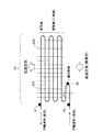
このように封入量調整ユニット30が装置本体20における作動流体の封入量を調整することにより、蒸発部22の最下層である流路221の一段目を流れる作動流体を過冷却状態にすることができる。つまり、蒸発部22の最下層は過冷却域になる。そして、流路221の二段目以上を流れる作動流体は、気液二相状態になり蒸発することができる。つまり、蒸発部22の中間層は蒸発域になり、蒸発部22の最上層は蒸気域になる。
In this way, by adjusting the amount of working fluid enclosed in the apparatus
以上のような構成を有する冷熱移送装置によれば、封入量調整ユニット30が、作動流体の封入量を調整して、蒸発部22の最下層である流路221の一段目を流れる作動流体を過冷却状態にするので、流路221の一段目を流れる作動流体が蒸発する虞れがない。そのため、蒸発部22で蒸発した作動流体が逆流してしまうことがなく、作動流体をスムーズに循環させることができ、これにより、効率的にスターリング冷凍機10の冷却端部11で発生した冷熱を移送することができ、スターリング冷凍機10の冷却効率を向上させることができる。また、従来のように特殊な加工を施す必要がないので、装置全体に要するコストが増大する虞れがない。
According to the cold transfer device having the above-described configuration, the enclosed amount adjusting unit 30 adjusts the enclosed amount of the working fluid so that the working fluid flowing through the first stage of the
また、上記冷熱移送装置によれば、作動流体の封入量を調整して作動流体の逆流を防ぐため、凝縮部21と蒸発部22との液面の高低差Hを拡大させて作動流体を循環させるのに必要なエネルギーを増大させる必要がなく、また、蒸発部22における冷却負荷による影響を受けることもない。
Further, according to the cold transfer device, the working fluid is circulated by expanding the liquid level difference H between the condensing
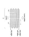
以上、本発明の好適な実施の形態について説明したが、本発明はこれに限定されるものではなく、種々の変更を行うことができる。例えば、図4に示したように、蒸発部22’の最下層である流路221の一段目の距離を短くしても良い。このような構成によれば、流路221の一段目の容積が小さくなる結果、流路221の入口221aから折返し個所にかけての作動流体の過冷却度を小さくすることができる。
The preferred embodiment of the present invention has been described above, but the present invention is not limited to this, and various modifications can be made. For example, as shown in FIG. 4, the first-stage distance of the
また、上記温度センサは、例えば自動販売機では除霜検知用に使用されているものを流用しても良い。これによれば、新たなセンサを必要とせず、コストの増大を防止することができる。 Moreover, you may divert the said temperature sensor used, for example in a vending machine for defrost detection. According to this, it is possible to prevent an increase in cost without requiring a new sensor.
以上のように、本発明に係る冷熱移送装置は、例えばスターリング冷凍機等の冷却装置の冷熱発生部で発生した冷熱を移送するのに有用である。 As described above, the cold heat transfer device according to the present invention is useful for transferring cold heat generated in a cold heat generating part of a cooling device such as a Stirling refrigerator.
10 スターリング冷凍機
11 冷却端部
12 放熱端部
20 装置本体
21 凝縮部
22 蒸発部
221 流路
222 熱交換用フィン
23 液体ライン
24 蒸気ライン
30 封入量調整ユニット
31 主制御部
32 温度検出部
33 バルブ制御部
34 メモリ
35,36,37 温度センサ
DESCRIPTION OF
Claims (3)
所定の冷却部位に配設した蒸発部と、
前記凝縮部で凝縮させた作動流体を前記蒸発部まで移動させるための液体ラインと、
前記蒸発部で蒸発させた作動流体を前記凝縮部まで移動させるための蒸気ラインと
を有して成る装置本体を備え、
前記装置本体に封入した作動流体を相変化させながら循環させて、前記冷熱発生部で発生した冷熱を所定の冷却部位に移送するようにした冷熱移送装置において、
前記作動流体の封入量を調整して、前記蒸発部の最下層における作動流体を過冷却状態にする封入量調整手段を備えたことを特徴とする冷熱移送装置。 A condensing part thermally connected to the cold heat generating part of the cooling device;
An evaporator disposed in a predetermined cooling site;
A liquid line for moving the working fluid condensed in the condensing unit to the evaporation unit;
An apparatus main body having a vapor line for moving the working fluid evaporated in the evaporation section to the condensation section,
In the cold heat transfer device in which the working fluid sealed in the device main body is circulated while changing the phase, and the cold heat generated in the cold heat generating unit is transferred to a predetermined cooling site,
An apparatus for transferring heat according to claim 1, further comprising: an amount-of-sealing adjusting means for adjusting the amount of the working fluid enclosed so that the working fluid in the lowermost layer of the evaporating unit is in a supercooled state.
所定の冷却部位に配設した蒸発部と、
前記凝縮部で凝縮させた作動流体を前記蒸発部まで移動させるための液体ラインと、
前記蒸発部で蒸発させた作動流体を前記凝縮部まで移動させるための蒸気ラインと
を有して成る装置本体を備え、
前記装置本体に封入した作動流体を相変化させながら循環させて、前記冷却端部で発生した冷熱を所定の冷却部位に移送するようにした冷熱移送装置において、
前記作動流体の封入量を調整して、前記蒸発部の最下層における作動流体を過冷却状態にする封入量調整手段を備えたことを特徴とする冷熱移送装置。 A condensing section thermally connected to the cooling end of the Stirling refrigerator,
An evaporator disposed in a predetermined cooling site;
A liquid line for moving the working fluid condensed in the condensing unit to the evaporation unit;
An apparatus main body having a vapor line for moving the working fluid evaporated in the evaporation section to the condensation section,
In the cold transfer device which circulates the working fluid sealed in the device main body while changing the phase, and transfers the cold generated at the cooling end to a predetermined cooling site,
An apparatus for transferring heat according to claim 1, further comprising: an amount-of-sealing adjusting means for adjusting the amount of the working fluid enclosed so that the working fluid in the lowermost layer of the evaporating unit is in a supercooled state.
Priority Applications (1)
| Application Number | Priority Date | Filing Date | Title |
|---|---|---|---|
| JP2004112235A JP2005299941A (en) | 2004-04-06 | 2004-04-06 | Cold transfer device |
Applications Claiming Priority (1)
| Application Number | Priority Date | Filing Date | Title |
|---|---|---|---|
| JP2004112235A JP2005299941A (en) | 2004-04-06 | 2004-04-06 | Cold transfer device |
Publications (1)
| Publication Number | Publication Date |
|---|---|
| JP2005299941A true JP2005299941A (en) | 2005-10-27 |
Family
ID=35331691
Family Applications (1)
| Application Number | Title | Priority Date | Filing Date |
|---|---|---|---|
| JP2004112235A Pending JP2005299941A (en) | 2004-04-06 | 2004-04-06 | Cold transfer device |
Country Status (1)
| Country | Link |
|---|---|
| JP (1) | JP2005299941A (en) |
Cited By (1)
| Publication number | Priority date | Publication date | Assignee | Title |
|---|---|---|---|---|
| WO2019092978A1 (en) * | 2017-11-07 | 2019-05-16 | 株式会社デンソー | Thermo-siphon type temperature adjusting apparatus |
-
2004
- 2004-04-06 JP JP2004112235A patent/JP2005299941A/en active Pending
Cited By (3)
| Publication number | Priority date | Publication date | Assignee | Title |
|---|---|---|---|---|
| WO2019092978A1 (en) * | 2017-11-07 | 2019-05-16 | 株式会社デンソー | Thermo-siphon type temperature adjusting apparatus |
| JP2019086214A (en) * | 2017-11-07 | 2019-06-06 | 株式会社デンソー | Thermo-siphon type temperature controller |
| JP7003582B2 (en) | 2017-11-07 | 2022-01-20 | 株式会社デンソー | Thermosiphon type temperature controller |
Similar Documents
| Publication | Publication Date | Title |
|---|---|---|
| JP4318567B2 (en) | Cooling system | |
| JP6046821B2 (en) | Refrigeration system defrost system and cooling unit | |
| JP2003322457A (en) | Dewfall preventing device of refrigerator | |
| US20060144053A1 (en) | Refrigerator | |
| WO2010001643A1 (en) | Cooling device and method for manufacturing the same | |
| JP2010181052A (en) | Heat pump device | |
| JP5436631B2 (en) | Refrigeration equipment | |
| JP2005326138A (en) | Cooling device and vending machine with it | |
| EP3586074B1 (en) | Refrigerator | |
| JP4945713B2 (en) | Cooling system | |
| US10145600B2 (en) | Refrigerator | |
| JP5219657B2 (en) | Cooling device and manufacturing method thereof | |
| KR20080041552A (en) | Air conditioner and air conditioning method | |
| KR101116138B1 (en) | Cooling system using separated heatpipes | |
| JP2005299941A (en) | Cold transfer device | |
| JP2006336943A (en) | Refrigeration system and cold storage | |
| JP4945712B2 (en) | Thermosiphon | |
| JP2005188813A (en) | Thermosiphon cooling device | |
| JP2007093112A (en) | Cooling storage | |
| JP2015224845A (en) | Refrigeration cycle device | |
| JP2009024884A (en) | Refrigeration cycle equipment and cold storage | |
| JP2012026686A (en) | Load-side device and refrigeration/cold-storage system | |
| JP4182148B2 (en) | accumulator | |
| JP4569545B2 (en) | Showcase | |
| JP4358759B2 (en) | Natural circulation cooling device control method and natural circulation cooling device |