JP2005299919A - Solenoid valve - Google Patents
Solenoid valve Download PDFInfo
- Publication number
- JP2005299919A JP2005299919A JP2004279763A JP2004279763A JP2005299919A JP 2005299919 A JP2005299919 A JP 2005299919A JP 2004279763 A JP2004279763 A JP 2004279763A JP 2004279763 A JP2004279763 A JP 2004279763A JP 2005299919 A JP2005299919 A JP 2005299919A
- Authority
- JP
- Japan
- Prior art keywords
- case
- plunger
- solenoid valve
- fluid
- groove
- Prior art date
- Legal status (The legal status is an assumption and is not a legal conclusion. Google has not performed a legal analysis and makes no representation as to the accuracy of the status listed.)
- Granted
Links
- 239000012530 fluid Substances 0.000 claims description 41
- 238000013016 damping Methods 0.000 claims description 12
- 238000007599 discharging Methods 0.000 abstract description 3
- 238000004891 communication Methods 0.000 description 11
- 230000000694 effects Effects 0.000 description 5
- 239000007788 liquid Substances 0.000 description 3
- 238000000034 method Methods 0.000 description 3
- 230000010349 pulsation Effects 0.000 description 3
- 230000005540 biological transmission Effects 0.000 description 2
- 238000010586 diagram Methods 0.000 description 2
- 230000033001 locomotion Effects 0.000 description 2
- 125000006850 spacer group Chemical group 0.000 description 2
- 230000004907 flux Effects 0.000 description 1
- 230000005484 gravity Effects 0.000 description 1
- 230000009545 invasion Effects 0.000 description 1
- 239000000314 lubricant Substances 0.000 description 1
- 239000000696 magnetic material Substances 0.000 description 1
- 239000000463 material Substances 0.000 description 1
Images
Landscapes
- Magnetically Actuated Valves (AREA)
Abstract
【課題】 プランジャの摺動部等への異物の侵入を抑制しつつも、ケースの加工上の困難性を伴わないようにすることを可能とすることができ、かつプランジャの振動を効果的に減衰することのできるソレノイドバルブを提供する。
【解決手段】 ドレンを排出するための流路を、サイドリング7の外向きフランジ部72におけるケース9の底への当接面側に設けられた溝73と、ケース9の筒状部分に設けられた貫通孔91によって形成し、外部の異物が、プランジャ3と軸受け12との摺動部や、弁体5と軸受け13との摺動部に入り込むことを極力防止するために、溝73の深さを非常に浅く設定する。
【選択図】 図1PROBLEM TO BE SOLVED: To prevent foreign matter from entering a sliding portion of a plunger and the like without causing difficulty in processing a case, and to effectively prevent vibration of the plunger. A solenoid valve that can be damped is provided.
SOLUTION: A flow path for discharging a drain is provided in a groove 73 provided on a contact surface side of the outward flange portion 72 of the side ring 7 to the bottom of the case 9 and a cylindrical portion of the case 9. In order to prevent external foreign matter from entering the sliding portion between the plunger 3 and the bearing 12 and the sliding portion between the valve body 5 and the bearing 13 as much as possible. Set the depth very shallow.
[Selection] Figure 1
Description
本発明は、ソレノイドバルブに関するものである。 The present invention relates to a solenoid valve.
図8は従来例に係るソレノイドバルブの模式的断面図である。この従来例に係るソレノイドバルブ100は、コイル101への通電・非通電に応じて移動するプランジャ102と、プランジャ102と共に移動して、弁を開いたり閉じたりする弁体103とを備える。また、このソレノイドバルブ100は、コイル101への通電時に磁路の一部を形成すると共に、コイル101やプランジャ102を収納する有底筒状のケース104を備える。そして、ケース104の底の部分には、プランジャ102と当該底との間の液体や気体を外部に排出させるためのドレン口104aが設けられている。
FIG. 8 is a schematic cross-sectional view of a solenoid valve according to a conventional example. The
この従来例に係るソレノイドバルブ100は、バルブ側が下方となり、ケース104の底の部分が上方となるように設置して利用される。そのため、外部の異物が、プランジャ102の摺動部などに侵入することを抑制させるためには、ドレン口104aの面積を極力小さくする必要がある。しかし、プレス加工上、ドレン口104aの面積を小さくするには限界がある。
本発明の目的の1つとして、プランジャの摺動部等への異物の侵入を抑制しつつも、ケースの加工上の困難性を伴わないようにすることが挙げられる。 One of the objects of the present invention is to prevent foreign matters from entering the sliding portion of the plunger, while avoiding the difficulty in processing the case.
また、本発明の他の目的の1つとして、プランジャの振動減衰効果を向上させることが挙げられる。 Another object of the present invention is to improve the vibration damping effect of the plunger.
本発明は、上記課題を解決するために以下の手段を採用した。 The present invention employs the following means in order to solve the above problems.
すなわち、本発明のソレノイドバルブは、有底筒状のケースと、
該ケース内に設けられたコイルへの通電時にはセンターポストに磁気的に吸引され、かつコイルへの非通電時にはセンターポストから引き離されるプランジャと、
該プランジャの周囲を取り囲む筒状部、及び前記ケースの底に当接するフランジ部とを有し、該ケースと共に前記コイルへの通電時に磁路の一部を形成する磁性部材と、を備え、
前記プランジャの動作によって弁を開いたり閉じたりすることで、流体の流量及び流体圧力のうちの少なくともいずれか一方を制御するソレノイドバルブにおいて、
前記プランジャの振動を減衰させる緩衝部材を設けると共に、
前記フランジ部のケースの底に対する当接面側に溝を設け、かつ、前記ケースの筒状部分に貫通孔を設けることによって、前記プランジャとケースの底との間の流体をケースの外部に逃がす流路が形成されることを特徴とするものが挙げられる。
That is, the solenoid valve of the present invention has a bottomed cylindrical case,
A plunger that is magnetically attracted to the center post when energized to the coil provided in the case, and is pulled away from the center post when de-energized to the coil;
A cylindrical portion that surrounds the periphery of the plunger, and a flange portion that contacts the bottom of the case, and a magnetic member that forms a part of a magnetic path when energizing the coil together with the case,
In a solenoid valve that controls at least one of a flow rate of fluid and a fluid pressure by opening or closing the valve by the operation of the plunger,
While providing a buffer member for damping the vibration of the plunger,
By providing a groove on the abutting surface side of the flange portion with respect to the bottom of the case and providing a through hole in the cylindrical portion of the case, the fluid between the plunger and the bottom of the case is released to the outside of the case. The thing characterized by forming a flow path is mentioned.
本発明の構成によれば、プランジャとケースの底との間の流体は、磁性部材のフランジ部に設けられた溝を通り、ケースに設けられた貫通孔から、ケースの外部に逃げることになる。従って、外部からの異物がプランジャの摺動部等にどの程度侵入するかを、ケースに設けられた貫通孔の大きさにかかわらず、磁性部材のフランジ部に設けられた溝の大き
さによって、決定付けさせることができる。従って、ケースに設けられた貫通孔の大きさを無理に小さくする必要がないことから、ケースの加工上の困難性が伴ってしまうことを防止できる。また、ケースの底側が上方となるようにソレノイドバルブが使用される場合であっても、ケースに設けられた貫通孔はケースの筒状部分に設けられていることから、異物の当該貫通孔からの侵入そのものを抑制できる。付言するに、一般的に、面積の小さな貫通孔を形成するのに比べて、深さの浅い溝を形成する方が、加工上(特に、プレス加工では)容易である。従って、簡易な加工により深さの浅い溝を形成することで、プランジャの摺動部等への異物の侵入を効果的に抑制することが可能である。
According to the configuration of the present invention, the fluid between the plunger and the bottom of the case passes through the groove provided in the flange portion of the magnetic member and escapes from the through hole provided in the case to the outside of the case. . Therefore, depending on the size of the groove provided in the flange portion of the magnetic member, regardless of the size of the through hole provided in the case, how much foreign matter enters the sliding portion of the plunger, etc. Can be determined. Therefore, since it is not necessary to forcibly reduce the size of the through hole provided in the case, it is possible to prevent the case from being difficult to process. Even when the solenoid valve is used so that the bottom side of the case is upward, the through hole provided in the case is provided in the cylindrical part of the case, so that The invasion itself can be suppressed. In addition, in general, it is easier to form a groove having a shallow depth than in the case of forming a through-hole having a small area (especially in press working). Therefore, by forming a shallow groove by simple processing, it is possible to effectively suppress the entry of foreign matter into the sliding portion of the plunger.
更に、プランジャの振動が、緩衝部材によって減衰されるため、安定した流量制御や流体圧力制御がなされる。そして、本発明においては、上述のように、プランジャとケースの底との間の流体は、磁性部材のフランジ部に設けられた溝を通っていくことから、プランジャとケースの底との間の流体自体もプランジャの振動を減衰させる機能を発揮する。従って、緩衝部材の減衰機能と相俟って、効果的にプランジャの振動を減衰させることが可能となる。 Furthermore, since the vibration of the plunger is damped by the buffer member, stable flow rate control and fluid pressure control are performed. In the present invention, as described above, the fluid between the plunger and the bottom of the case passes through the groove provided in the flange portion of the magnetic member. The fluid itself also functions to attenuate the plunger vibration. Accordingly, in combination with the damping function of the buffer member, the vibration of the plunger can be effectively damped.
また、本発明のソレノイドバルブは、有底筒状のケースと、
該ケース内に設けられたコイルへの通電時にはセンターポストに磁気的に吸引され、かつコイルへの非通電時にはセンターポストから引き離されるプランジャと、
該プランジャの周囲を取り囲む筒状部、及び前記ケースの底に当接するフランジ部とを有し、該ケースと共に前記コイルへの通電時に磁路の一部を形成する磁性部材と、を備え、
前記プランジャの動作によって弁を開いたり閉じたりすることで、流体の流量及び流体圧力のうちの少なくともいずれか一方を制御するソレノイドバルブにおいて、
前記プランジャの振動を減衰させる緩衝部材を設けると共に、
前記ケースの底の前記フランジ部に対する当接面側に溝を設け、かつ、前記ケースの筒状部分に貫通孔を設けることによって、前記プランジャとケースの底との間の流体をケースの外部に逃がす流路が形成されることを特徴とする。
The solenoid valve of the present invention includes a bottomed cylindrical case,
A plunger that is magnetically attracted to the center post when energized to the coil provided in the case, and is pulled away from the center post when de-energized to the coil;
A cylindrical portion that surrounds the periphery of the plunger, and a flange portion that contacts the bottom of the case, and a magnetic member that forms a part of a magnetic path when energizing the coil together with the case,
In a solenoid valve that controls at least one of a flow rate of fluid and a fluid pressure by opening or closing the valve by the operation of the plunger,
While providing a buffer member for damping the vibration of the plunger,
By providing a groove on the abutting surface side of the bottom of the case with respect to the flange portion and providing a through hole in the cylindrical portion of the case, fluid between the plunger and the bottom of the case is placed outside the case. A flow path for escaping is formed.
本発明の構成によれば、プランジャとケースの底との間の流体は、ケースに設けられた溝を通り、ケースに設けられた貫通孔から、ケースの外部に逃げることになる。従って、外部からの異物がプランジャの摺動部等にどの程度侵入するかを、ケースに設けられた貫通孔の大きさにかかわらず、ケースに設けられた溝の大きさによって、決定付けさせることができる。従って、ケースに設けられた貫通孔の大きさを無理に小さくする必要がないことから、ケースの加工上の困難性が伴ってしまうことを防止できる。また、ケースの底側が上方となるようにソレノイドバルブが使用される場合であっても、ケースに設けられた貫通孔はケースの筒状部分に設けられていることから、異物の当該貫通孔からの侵入そのものを抑制できる。付言するに、一般的に、面積の小さな貫通孔を形成するのに比べて、深さの浅い溝を形成する方が、加工上(特に、プレス加工では)容易である。従って、簡易な加工により深さの浅い溝を形成することで、プランジャの摺動部等への異物の侵入を効果的に抑制することが可能である。 According to the configuration of the present invention, the fluid between the plunger and the bottom of the case passes through the groove provided in the case and escapes from the through hole provided in the case to the outside of the case. Therefore, the extent to which foreign matter enters the sliding part of the plunger is determined by the size of the groove provided in the case, regardless of the size of the through-hole provided in the case. Can do. Therefore, since it is not necessary to forcibly reduce the size of the through hole provided in the case, it is possible to prevent the case from being difficult to process. Even when the solenoid valve is used so that the bottom side of the case is upward, the through hole provided in the case is provided in the cylindrical part of the case, so that Intrusion itself can be suppressed. In addition, in general, it is easier to form a groove having a shallow depth than in the case of forming a through-hole having a small area (especially in press working). Therefore, by forming a shallow groove by simple processing, it is possible to effectively suppress the entry of foreign matter into the sliding portion of the plunger.
更に、プランジャの振動が、緩衝部材によって減衰されるため、安定した流量制御や流体圧力制御がなされる。そして、本発明においては、上述のように、プランジャとケースの底との間の流体は、ケースに設けられた溝を通っていくことから、プランジャとケースの底との間の流体自体もプランジャの振動を減衰させる機能を発揮する。従って、緩衝部材の減衰機能と相俟って、効果的にプランジャの振動を減衰させることが可能となる。 Furthermore, since the vibration of the plunger is damped by the buffer member, stable flow rate control and fluid pressure control are performed. In the present invention, as described above, since the fluid between the plunger and the bottom of the case passes through the groove provided in the case, the fluid itself between the plunger and the bottom of the case is also the plunger. Demonstrates the function to damp vibrations. Accordingly, in combination with the damping function of the buffer member, the vibration of the plunger can be effectively damped.
以上説明したように、本発明によれば、プランジャの摺動部等への異物の侵入を抑制し
つつも、ケースの加工上の困難性が伴ってしまうことを防止できる。また、プランジャの振動減衰効果を向上させることができる。
As described above, according to the present invention, it is possible to prevent the case from being difficult to process while suppressing the entry of foreign matter into the sliding portion of the plunger. In addition, the vibration damping effect of the plunger can be improved.
以下に図面を参照して、この発明を実施するための最良の形態を、実施例に基づいて例示的に詳しく説明する。ただし、この実施例に記載されている構成部品の寸法、材質、形状、その相対配置などは、特に特定的な記載がない限りは、この発明の範囲をそれらのみに限定する趣旨のものではない。 The best mode for carrying out the present invention will be exemplarily described in detail below with reference to the drawings. However, the dimensions, materials, shapes, relative arrangements, and the like of the components described in this embodiment are not intended to limit the scope of the present invention only to those unless otherwise specified. .
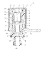
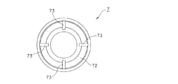
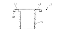
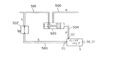
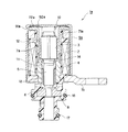
図1〜図4を参照して、本発明の実施例1に係るソレノイドバルブについて説明する。図1は本発明の実施例1に係るソレノイドバルブの模式的断面図(軸心を通るように切断した模式的断面図)である。図2は本発明の実施例1に係るソレノイドバルブの構成部品であるサイドリングの上面図である。図3は本発明の実施例1に係るソレノイドバルブの構成部品であるサイドリングの断面図(軸心を通るように切断した断面図)である。図4は本発明の実施例に係るソレノイドバルブを適用した油圧制御システム図である。
With reference to FIGS. 1-4, the solenoid valve which concerns on Example 1 of this invention is demonstrated. FIG. 1 is a schematic cross-sectional view (schematic cross-sectional view cut along an axis) of a solenoid valve according to
<ソレノイドバルブの全体説明>
本発明の実施例に係るソレノイドバルブ全体について説明する。本実施例に係るソレノイドバルブ1は、通電により磁界を発生するコイル2と、コイル2によって発生した磁界により磁気回路が形成されることでセンターポスト4に磁気的に吸引されるプランジャ3と、プランジャ3に一体的に設けられ、プランジャ3と共に移動する弁体5と、弁体5の弁座6と、プランジャ3の周囲を取り囲むように設けられる磁性部材であるサイドリング7と、ボビン81を一体的に備えたバルブボディ8と、有底筒状のケース9とを備えている。
<Overall description of solenoid valve>
An entire solenoid valve according to an embodiment of the present invention will be described. The
また、ソレノイドバルブ1は、その他にも、コイル2への非通電時に、弁体5を弁座6から離して弁を開いておくために、プランジャ3の位置を規制すると共に、プランジャ3の振動を減衰させる緩衝部材としての機能を発揮する2つのスプリング10,11を備えている。更に、ソレノイドバルブ1は、プランジャ3の軸受け12と、弁体5の軸受け13と、サイドリング7とセンターポスト4との間に設けられ、磁路をプランジャ3側に迂回させるようにして、これらの間で直接磁路が繋がらないようにするスペーサ14と、磁気回路の一部を構成すると共に、ソレノイドバルブ1を所望の取り付け位置に取り付けるためのブラケット15と、流体が所定の流路から漏れないようにするシールリング16,17とを備えている。
In addition, the
プランジャ3,センターポスト4,ブラケット15,ケース9、及びサイドリング7は磁性体により構成されている。そして、コイル2への通電時には、これらによって、列挙した順序、あるいはその逆の順序の磁気回路が形成される。これにより、プランジャ3は、スプリング10,11のばね力に抗してセンターポスト4に磁気的に吸引される。なお、本実施例では、センターポスト4に設けられるプランジャ3が当接するための段差部分41の面積を小さくしており、この部分への異物の付着を抑制させている。
The
また、サイドリング7は、プランジャ3の周囲を取り囲む筒状部71と、筒状部71の端部から外向き方向に延びる外向きフランジ部72とを備えている。そして、外向きフランジ部72は、一面がケース9の底に当接している。これにより、外向きフランジ部72とケース9との間で磁束が漏れないようにしている。
The
また、バルブボディ8は、バルブ先端側が筒状部82により構成されており、この筒状部82における弁座6よりも先端側と他端側に、それぞれ筒の内部に連通する第1連通孔
83及び第2連通孔84が設けられている。また、このバルブボディ8の内部に備えられた弁座6には、貫通孔61が設けられている。そして、上述の弁体5が弁座6に着座すると、貫通孔61が塞がれるため弁が閉じた状態となり、弁体5が弁座6から離れると、貫通孔61と第2連通孔84が通じ、弁が開いた状態となる。
Further, the
<ソレノイドバルブの使用例>
上述のように構成されたソレノイドバルブ1の使用の一例を説明する。このソレノイドバルブ1を利用して、例えば、筒状部82に設けられた第1連通孔83を入口(以下、流入ポートと称する)として、筒状部82の先端の開口部を出口(以下、制御ポートと称する)とし、制御ポートから出る流体の流量、あるいは流体圧力を制御することが可能である。すなわち、コイル2に対する通電量が所定量以上の状態では、弁は閉じられるため、流入ポートから入った流体は全て制御ポートから出て行く。一方、コイル2に対して通電を行っていない状態またはコイル2に対する通電量が所定量以下の状態では、弁が開かれるため、流体の一部は弁座6の貫通孔61を抜けて、第2連通孔84や後述する貫通孔91からソレノイドバルブ1の外部へと流出する。なお、この第2連通孔84と貫通孔91はドレンポートとなる。また、コイル2への通電量に応じてプランジャ3及び弁体5の移動量が変わり、弁の開き具合が変わる。従って、コイル2への通電量により、ドレンポートから流出させる流量を制御できる。以上のことから、制御ポートから出て行く流体の流量、あるいは流体圧力を制御することができる。
<Examples of using solenoid valves>
An example of the use of the
次に、図4を参照して、本実施例に係るソレノイドバルブ1のより具体的な適用例を説明する。図4は、自動車における、オートマチックトランスミッションの油圧制御のシステムを示したものである。
Next, a more specific application example of the
図示のように、ライン圧Lのオイルが供給される第1流路501に減圧弁502が接続されている。そして、この減圧弁502で一定圧に制御されたソレノイド供給圧Sのオイルが第2流路503に供給され、ソレノイドバルブ1の流入ポート(第1連通孔83)に導かれる。
As illustrated, a
そして、ソレノイドバルブ1によってパイロット圧Pに制御されたオイルが、制御ポート(筒状部82の先端の開口部)からスプール弁505に通じる第3流路504に導かれる。このとき、不要なオイルは、ドレンポート(第2連通孔84と貫通孔91)から排出される。
Then, the oil controlled to the pilot pressure P by the
スプール弁505には、上述の第1流路501,第3流路504の他に、更に、不図示のクラッチを切り替えるためのピストン油室に通じる第4流路506が接続されている。そして、基圧であるライン圧Lとソレノイドバルブ1で制御された作動信号圧であるパイロット圧Pによって、スプール弁505において第4流路506に導かれる出力圧Oが制御される。そして、この出力圧Oによって、不図示のピストン油室内の圧力が変わり、クラッチの切り替えが行われる。
In addition to the
<ドレン用の流路>
本実施例に係るソレノイドバルブ1においては、貫通孔61から第2連通孔84に抜けていく流体の量が過剰な場合に流体の一部を逃がすことを目的として、また、弁体5と軸受け13との間の摺動抵抗、及びプランジャ3と軸受け12との間の摺動抵抗を減らすことを目的として(流体が油等の場合には、当該流体が潤滑剤として機能する)、貫通孔61を抜けた流体の一部が、プランジャ3とケース9の底との間の隙間の領域まで流れていく流路が設けられている。この流路は、例えば、プランジャ3と軸受け12のうち少なくとも一方、及び弁体5と軸受け13のうち少なくとも一方に設けられた溝や貫通孔によって構成される。なお、本実施例では、プランジャ3の中心に貫通孔31が設けられ、かつ
プランジャ3と弁体5の接続部分付近に、貫通孔31からセンターポスト4と弁体5との隙間まで通じる連通孔(不図示)が設けられ、更に、軸受け13の内壁面に溝(不図示)が設けられており、これらによって上記の流路が形成されている。
<Flow path for drain>
In the
また、上記の流路を通じて、プランジャ3とケース9の底との間の隙間の領域まで流れてきたドレン(例えば、流量や流体圧力の制御に寄与せずに不要となった液体、及び当該液体に混入していた気体(空気など))をソレノイドバルブ1の外部に排出させるための流路が更に必要である。
In addition, the drain that has flowed through the flow path to the area of the gap between the
そこで、本実施例においては、サイドリング7の外向きフランジ部72におけるケース9の底への当接面側に溝73を設けると共に、ケース9の筒状部分に貫通孔91を設けることによって、ドレン用の流路を形成している。これにより、第2連通孔84と共に貫通孔91は上記のようにドレンポートとして機能する。そして、外部の異物が、プランジャ3と軸受け12との摺動部や、弁体5と軸受け13との摺動部に入り込むことを極力防止するために、溝73の深さを非常に浅く設定している。この溝73は、サイドリング7をプレス加工する際に形成することができ、溝73の深さを浅くすることも一般的に簡単である。なお、このように形成されるドレン用の流路における最低限必要な流路断面積の総計は、溝73の深さの他に、溝73の幅や溝73の個数によっても変えることができる。このことからも、溝73の深さを非常に浅くすることができ、外部からの異物の侵入を効果的に抑制することができる。
Therefore, in this embodiment, by providing the
このように、本実施例では、ドレン用の流路の流路断面積を最低限確保しつつ、プランジャ3の摺動部等への異物の侵入を、サイドリング7の外向きフランジ部72とケース9の底との間の部分で防止する構成を採用した。そのため、ケース9に設ける貫通孔91の面積を無理に小さくする必要がなく、ある程度自由に設定できる。従って、ケース9も簡単にプレス加工により成形することができる。以上のことから、ケース9等の加工上の困難性を伴うことなく、プランジャ3の摺動部等への異物の侵入を効果的に抑制することができる。
Thus, in the present embodiment, the entry of foreign matter into the sliding portion of the
また、本実施例では、ソレノイドバルブ1は、バルブ側が下方となり、ケース9の底の部分が上方となるように設置されて利用される。そして、本実施例においては、ドレン排出用の貫通孔91がケース9の筒状部に設けられているため、重力に従って落ちてくる異物は貫通孔91から入りにくい。従って、貫通孔91からの異物の侵入そのものを抑制することができる。
In this embodiment, the
また、プランジャ3は、流体の流れによって振動する可能性がある。例えば、上述のオートマチックトランスミッションの油圧制御としてソレノイドバルブ1を用いた場合には、油圧の脈動により、プランジャ3が振動する可能性がある。この脈動は、例えば、ポンプ脈動などによって生じるものである。そこで、本実施例では、上記の通り、プランジャ3の振動を、2つのスプリング10,11によって減衰させている。
Further, the
ここで、従来例のように、ケースの底にドレン口を設ける構成の場合には、プランジャとケースの底との間の流体は、ほとんど抵抗なく、ドレン口から外に抜けていく。そのため、プランジャの振動減衰効果はスプリングのみに頼ることになる。これに対して、本実施例では、プランジャ3の振動方向(プランジャ3の往復移動方向である軸方向)に対して垂直な方向に、プランジャ3とケース9の底との間の流体が抜けていく流路を設けている。更に、上記の通り、サイドリング7の外向きフランジ部72に設けた非常に浅い溝73によって、ドレン用の流路の一部を形成している。従って、プランジャ3がケース9の底側に移動する場合には、プランジャ3とケース9の底との間の隙間の領域に溜まった流体の流体圧力が、プランジャ3の移動に対する抵抗力となる。従って、この抵抗力が、ス
プリング10,11と同様に、プランジャ3の振動を減衰させる機能を発揮する。以上のように、ドレン用の流路構成を工夫したことにより、スプリング10,11による減衰効果と相俟って、プランジャ3とケース9の底との間の隙間の領域に溜まった流体の流体圧力によって、効果的にプランジャ3の振動を減衰させることができる。
Here, as in the conventional example, in the case where the drain port is provided at the bottom of the case, the fluid between the plunger and the bottom of the case flows out from the drain port with almost no resistance. Therefore, the vibration damping effect of the plunger depends on only the spring. On the other hand, in this embodiment, the fluid between the
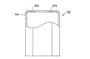
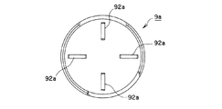
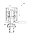
図5〜図7には、本発明の実施例2が示されている。上記実施例1では、サイドリングの外向きフランジ部に溝を設けることによって、ドレン用の流路の一部を形成する場合を示した。これに対して、本実施例では、ケースの底の面に溝を設けることによって、ドレン用の流路の一部を形成する場合を示す。その他の構成および作用については実施例1と同一なので、同一の構成部分については同一の符号を付して、その説明は省略する。 5 to 7 show a second embodiment of the present invention. In the first embodiment, the case where a part of the drain channel is formed by providing a groove in the outward flange portion of the side ring is shown. On the other hand, in this embodiment, a case where a part of the drain flow path is formed by providing a groove on the bottom surface of the case is shown. Since other configurations and operations are the same as those in the first embodiment, the same components are denoted by the same reference numerals and description thereof is omitted.
図5は本発明の実施例2に係るソレノイドバルブの模式的断面図(軸心を通るように切断した模式的断面図)である。図6は本発明の実施例2に係るソレノイドバルブの構成部品であるケースの一部破断断面図(一部を軸心を通るように切断した破断断面図)である。図7は本発明の実施例2に係るソレノイドバルブの構成部品であるケースの底面図である。 FIG. 5 is a schematic cross-sectional view (schematic cross-sectional view cut through the shaft center) of the solenoid valve according to the second embodiment of the present invention. FIG. 6 is a partially cutaway sectional view of a case which is a component part of a solenoid valve according to a second embodiment of the present invention (a cutaway sectional view in which a part is cut through an axis). FIG. 7 is a bottom view of a case which is a component part of the solenoid valve according to the second embodiment of the present invention.
本実施例に係るソレノイドバルブ1aにおいては、ケース9aの底の外向きフランジ部72aに対する当接面側に溝92aを設けると共に、ケース9aの筒状部分に貫通孔91aを設けることによって、ドレン用の流路を形成している。なお、溝92aは、サイドリング7aの外向きフランジ部72aがケース9aの底面に当接した状態でも、サイドリング7aの筒状部71aにおける内側の領域から外側の領域まで流路を確保するように、形成されている。なお、本実施例においてはサイドリング7a側にはドレン用の流路を形成するための溝は設けられていない。ドレン用の流路を形成するための溝に関する構成以外については、本実施例に係るソレノイドバルブ1aと上記実施例1に係るソレノイドバルブ1と同一の構成である。
In the solenoid valve 1a according to the present embodiment, the
以上の構成により、本実施例においても、上記実施例1と同様に、貫通孔91aはドレンポートとして機能する。そして、外部の異物が、プランジャ3と軸受け12との摺動部や、弁体5と軸受け13との摺動部に入り込むことを極力防止するために、溝92aの深さを非常に浅く設定している。この溝92aは、ケース9aをプレス加工する際に形成することができ、溝92aの深さを浅くすることも一般的に簡単である。なお、このように形成されるドレン用の流路における最低限必要な流路断面積の総計は、溝92aの深さの他に、溝92aの幅や溝92aの個数によっても変えることができる。このことからも、溝92aの深さを非常に浅くすることができ、外部からの異物の侵入を効果的に抑制することができる。
With the above configuration, in this embodiment as well, the through
このように、本実施例においても、上記実施例1と同様に、ドレン用の流路の流路断面積を最低限確保しつつ、プランジャ3の摺動部等への異物の侵入を、サイドリング7aの外向きフランジ部72aとケース9aの底との間の部分で防止する構成を採用した。そのため、ケース9aに設ける貫通孔91aの面積を無理に小さくする必要がなく、ある程度自由に設定できる。従って、ケース9aも簡単にプレス加工により成形することができる。以上のことから、ケース9a等の加工上の困難性を伴うことなく、プランジャ3の摺動部等への異物の侵入を効果的に抑制することができる。
Thus, in this embodiment as well, in the same manner as in the first embodiment, it is possible to prevent foreign matter from entering the sliding portion of the
また、本実施例においても、上記実施例1と同様に、ソレノイドバルブ1aは、バルブ側が下方となり、ケース9aの底の部分が上方となるように設置されて利用される。従って、貫通孔91aからの異物の侵入そのものを抑制することができる。
Also in the present embodiment, similarly to the first embodiment, the solenoid valve 1a is installed and used such that the valve side is downward and the bottom portion of the
更に、本実施例においても、上記実施例1と同様に、ドレン用の流路構成を工夫したことにより、スプリング10,11による減衰効果と相俟って、プランジャ3とケース9aの底との間の隙間の領域に溜まった流体の流体圧力によって、効果的にプランジャ3の振動を減衰させることができる。
Further, in the present embodiment as well, in the same way as in the first embodiment, by contriving the drain flow path configuration, the
(その他)
上記実施例1においては、サイドリングの外向きフランジ部側にのみ溝を形成することで、ドレン用の流路を形成する場合を示した。また、上記実施例2においては、ケースの底面側にのみ溝を形成することで、ドレン用の流路を形成する場合を示した。
(Other)
In the said Example 1, the case where the flow path for drains was formed was shown by forming a groove | channel only in the outward flange part side of a side ring. Moreover, in the said Example 2, the case where the flow path for drains was formed by forming a groove | channel only in the bottom face side of a case was shown.
しかしながら、サイドリングの外向きフランジ部側及びケースの底面側の両方に溝を設けて、ドレン用の流路を形成しても良いことは言うまでもない。この場合、両者の溝を重ねて1本の流路を形成しても良いし、両者の溝をそれぞれ独立させて、各々別の流路としても良い。 However, it goes without saying that a channel for draining may be formed by providing grooves on both the outward flange portion side of the side ring and the bottom surface side of the case. In this case, the two grooves may be overlapped to form a single flow path, or the two grooves may be made independent to form separate flow paths.
1 ソレノイドバルブ
2 コイル
3 プランジャ
31 貫通孔
4 センターポスト
41 段差部分
5 弁体
6 弁座
61 貫通孔
7,7a サイドリング
71,71a 筒状部
72,72a 外向きフランジ部
73 溝
8 バルブボディ
81 ボビン
82 筒状部
83 第1連通孔
84 第2連通孔
9,9a ケース
91,91a 貫通孔
92a 溝
10,11 スプリング
12,13 軸受け
14 スペーサ
15 ブラケット
16,17 シールリング
501 第1流路
502 減圧弁
503 第2流路
504 第3流路
505 スプール弁
506 第4流路
DESCRIPTION OF
Claims (2)
該ケース内に設けられたコイルへの通電時にはセンターポストに磁気的に吸引され、かつコイルへの非通電時にはセンターポストから引き離されるプランジャと、
該プランジャの周囲を取り囲む筒状部、及び前記ケースの底に当接するフランジ部とを有し、該ケースと共に前記コイルへの通電時に磁路の一部を形成する磁性部材と、を備え、
前記プランジャの動作によって弁を開いたり閉じたりすることで、流体の流量及び流体圧力のうちの少なくともいずれか一方を制御するソレノイドバルブにおいて、
前記プランジャの振動を減衰させる緩衝部材を設けると共に、
前記フランジ部のケースの底に対する当接面側に溝を設け、かつ、前記ケースの筒状部分に貫通孔を設けることによって、前記プランジャとケースの底との間の流体をケースの外部に逃がす流路が形成されることを特徴とするソレノイドバルブ。 A bottomed cylindrical case,
A plunger that is magnetically attracted to the center post when energized to the coil provided in the case, and is pulled away from the center post when de-energized to the coil;
A cylindrical portion that surrounds the periphery of the plunger, and a flange portion that contacts the bottom of the case, and a magnetic member that forms a part of a magnetic path when energizing the coil together with the case,
In a solenoid valve that controls at least one of a flow rate of fluid and a fluid pressure by opening or closing the valve by the operation of the plunger,
While providing a buffer member for damping the vibration of the plunger,
By providing a groove on the abutting surface side of the flange portion with respect to the bottom of the case and providing a through hole in the cylindrical portion of the case, the fluid between the plunger and the bottom of the case is released to the outside of the case. A solenoid valve characterized in that a flow path is formed.
該ケース内に設けられたコイルへの通電時にはセンターポストに磁気的に吸引され、かつコイルへの非通電時にはセンターポストから引き離されるプランジャと、
該プランジャの周囲を取り囲む筒状部、及び前記ケースの底に当接するフランジ部とを有し、該ケースと共に前記コイルへの通電時に磁路の一部を形成する磁性部材と、を備え、
前記プランジャの動作によって弁を開いたり閉じたりすることで、流体の流量及び流体圧力のうちの少なくともいずれか一方を制御するソレノイドバルブにおいて、
前記プランジャの振動を減衰させる緩衝部材を設けると共に、
前記ケースの底の前記フランジ部に対する当接面側に溝を設け、かつ、前記ケースの筒状部分に貫通孔を設けることによって、前記プランジャとケースの底との間の流体をケースの外部に逃がす流路が形成されることを特徴とするソレノイドバルブ。 A bottomed cylindrical case,
A plunger that is magnetically attracted to the center post when energized to the coil provided in the case, and is pulled away from the center post when de-energized to the coil;
A cylindrical portion that surrounds the periphery of the plunger, and a flange portion that contacts the bottom of the case, and a magnetic member that forms a part of a magnetic path when energizing the coil together with the case,
In a solenoid valve that controls at least one of a flow rate of fluid and a fluid pressure by opening or closing the valve by the operation of the plunger,
While providing a buffer member for damping the vibration of the plunger,
By providing a groove on the abutting surface side of the bottom of the case with respect to the flange portion and providing a through hole in the cylindrical portion of the case, fluid between the plunger and the bottom of the case is placed outside the case. A solenoid valve characterized in that a flow passage for escape is formed.
Priority Applications (1)
| Application Number | Priority Date | Filing Date | Title |
|---|---|---|---|
| JP2004279763A JP4543857B2 (en) | 2004-03-16 | 2004-09-27 | Solenoid valve |
Applications Claiming Priority (2)
| Application Number | Priority Date | Filing Date | Title |
|---|---|---|---|
| JP2004074631 | 2004-03-16 | ||
| JP2004279763A JP4543857B2 (en) | 2004-03-16 | 2004-09-27 | Solenoid valve |
Publications (2)
| Publication Number | Publication Date |
|---|---|
| JP2005299919A true JP2005299919A (en) | 2005-10-27 |
| JP4543857B2 JP4543857B2 (en) | 2010-09-15 |
Family
ID=35331678
Family Applications (1)
| Application Number | Title | Priority Date | Filing Date |
|---|---|---|---|
| JP2004279763A Expired - Lifetime JP4543857B2 (en) | 2004-03-16 | 2004-09-27 | Solenoid valve |
Country Status (1)
| Country | Link |
|---|---|
| JP (1) | JP4543857B2 (en) |
Cited By (6)
| Publication number | Priority date | Publication date | Assignee | Title |
|---|---|---|---|---|
| WO2008117714A1 (en) | 2007-03-23 | 2008-10-02 | Eagle Industry Co., Ltd. | Solenoid valve and method for manufacturing the same |
| JP2011009381A (en) * | 2009-06-24 | 2011-01-13 | Keihin Corp | Linear solenoid and valve device using the same |
| JP2011077355A (en) * | 2009-09-30 | 2011-04-14 | Keihin Corp | Linear solenoid and valve device using the same |
| JP2015060953A (en) * | 2013-09-19 | 2015-03-30 | 株式会社デンソー | Linear solenoid |
| US9263931B2 (en) | 2013-09-19 | 2016-02-16 | Denso Corporation | Linear solenoid and manufacturing method of the same |
| US9349515B2 (en) | 2013-09-19 | 2016-05-24 | Denso Corporation | Linear solenoid |
Citations (12)
| Publication number | Priority date | Publication date | Assignee | Title |
|---|---|---|---|---|
| JPS629771U (en) * | 1985-07-03 | 1987-01-21 | ||
| JPS6318686U (en) * | 1986-07-23 | 1988-02-06 | ||
| JPS6328807U (en) * | 1986-08-08 | 1988-02-25 | ||
| JPH0620966U (en) * | 1992-06-23 | 1994-03-18 | 株式会社ユニシアジェックス | Pressure control valve |
| JPH0728273U (en) * | 1993-10-28 | 1995-05-23 | エヌオーケー株式会社 | solenoid |
| JPH11210919A (en) * | 1998-01-27 | 1999-08-06 | Denso Corp | Spool valve type hydraulic control valve |
| JP2002310322A (en) * | 2001-04-17 | 2002-10-23 | Denso Corp | Solenoid valve device |
| JP2003207066A (en) * | 2002-01-16 | 2003-07-25 | Nidec Tosok Corp | Solenoid valve |
| JP2003329164A (en) * | 2002-03-05 | 2003-11-19 | Denso Corp | Solenoid valve |
| JP2004197859A (en) * | 2002-12-19 | 2004-07-15 | Nok Corp | Solenoid valve and its manufacturing method |
| JP2004263856A (en) * | 2003-02-13 | 2004-09-24 | Toyoda Mach Works Ltd | Solenoid valve |
| JP2005282631A (en) * | 2004-03-29 | 2005-10-13 | Nidec Tosok Corp | Solenoid valve structure |
-
2004
- 2004-09-27 JP JP2004279763A patent/JP4543857B2/en not_active Expired - Lifetime
Patent Citations (12)
| Publication number | Priority date | Publication date | Assignee | Title |
|---|---|---|---|---|
| JPS629771U (en) * | 1985-07-03 | 1987-01-21 | ||
| JPS6318686U (en) * | 1986-07-23 | 1988-02-06 | ||
| JPS6328807U (en) * | 1986-08-08 | 1988-02-25 | ||
| JPH0620966U (en) * | 1992-06-23 | 1994-03-18 | 株式会社ユニシアジェックス | Pressure control valve |
| JPH0728273U (en) * | 1993-10-28 | 1995-05-23 | エヌオーケー株式会社 | solenoid |
| JPH11210919A (en) * | 1998-01-27 | 1999-08-06 | Denso Corp | Spool valve type hydraulic control valve |
| JP2002310322A (en) * | 2001-04-17 | 2002-10-23 | Denso Corp | Solenoid valve device |
| JP2003207066A (en) * | 2002-01-16 | 2003-07-25 | Nidec Tosok Corp | Solenoid valve |
| JP2003329164A (en) * | 2002-03-05 | 2003-11-19 | Denso Corp | Solenoid valve |
| JP2004197859A (en) * | 2002-12-19 | 2004-07-15 | Nok Corp | Solenoid valve and its manufacturing method |
| JP2004263856A (en) * | 2003-02-13 | 2004-09-24 | Toyoda Mach Works Ltd | Solenoid valve |
| JP2005282631A (en) * | 2004-03-29 | 2005-10-13 | Nidec Tosok Corp | Solenoid valve structure |
Cited By (7)
| Publication number | Priority date | Publication date | Assignee | Title |
|---|---|---|---|---|
| WO2008117714A1 (en) | 2007-03-23 | 2008-10-02 | Eagle Industry Co., Ltd. | Solenoid valve and method for manufacturing the same |
| JP2011009381A (en) * | 2009-06-24 | 2011-01-13 | Keihin Corp | Linear solenoid and valve device using the same |
| JP2011077355A (en) * | 2009-09-30 | 2011-04-14 | Keihin Corp | Linear solenoid and valve device using the same |
| US8556232B2 (en) | 2009-09-30 | 2013-10-15 | Keihin Corporation | Linear solenoid and valve device using the same |
| JP2015060953A (en) * | 2013-09-19 | 2015-03-30 | 株式会社デンソー | Linear solenoid |
| US9263931B2 (en) | 2013-09-19 | 2016-02-16 | Denso Corporation | Linear solenoid and manufacturing method of the same |
| US9349515B2 (en) | 2013-09-19 | 2016-05-24 | Denso Corporation | Linear solenoid |
Also Published As
| Publication number | Publication date |
|---|---|
| JP4543857B2 (en) | 2010-09-15 |
Similar Documents
| Publication | Publication Date | Title |
|---|---|---|
| JP5615286B2 (en) | Solenoid valve | |
| KR101638892B1 (en) | A control valve | |
| US8678341B2 (en) | Normally closed solenoid valve | |
| JP4244805B2 (en) | solenoid valve | |
| JP2004504566A (en) | Proportional pressure control valve | |
| JP4562885B2 (en) | Bidirectional pilot type electromagnetic flow path on-off valve and bidirectional piping | |
| CN102428306B (en) | Flow rate control valve | |
| JP2010116979A (en) | Backflow preventive device | |
| JPS6141090A (en) | Solenoid valve | |
| JP4543857B2 (en) | Solenoid valve | |
| JP2009008221A (en) | Valve device | |
| JP2015222108A (en) | Cylinder device | |
| US6708725B2 (en) | Valve, particularly solenoid valve | |
| JP2002272080A (en) | Solenoid-type actuator with shaft | |
| JP2005513390A (en) | Solenoid valves, especially for automatic transmissions | |
| JP4457740B2 (en) | Solenoid valve | |
| JP5453175B2 (en) | Pilot operated solenoid valve | |
| WO2006132120A1 (en) | Pilot solenoid valve | |
| JP4470538B2 (en) | Solenoid valve | |
| CN107289172B (en) | Electromagnetic valve | |
| KR20070005145A (en) | Solenoid valve | |
| JP4110894B2 (en) | Solenoid valve | |
| JPH09269079A (en) | Solenoid valve | |
| JPH0626780Y2 (en) | Low noise electromagnetic poppet valve | |
| JPS627909Y2 (en) |
Legal Events
| Date | Code | Title | Description |
|---|---|---|---|
| A621 | Written request for application examination |
Free format text: JAPANESE INTERMEDIATE CODE: A621 Effective date: 20070615 |
|
| A977 | Report on retrieval |
Free format text: JAPANESE INTERMEDIATE CODE: A971007 Effective date: 20091027 |
|
| A131 | Notification of reasons for refusal |
Free format text: JAPANESE INTERMEDIATE CODE: A131 Effective date: 20091110 |
|
| A521 | Request for written amendment filed |
Free format text: JAPANESE INTERMEDIATE CODE: A523 Effective date: 20091224 |
|
| TRDD | Decision of grant or rejection written | ||
| A01 | Written decision to grant a patent or to grant a registration (utility model) |
Free format text: JAPANESE INTERMEDIATE CODE: A01 Effective date: 20100608 |
|
| A01 | Written decision to grant a patent or to grant a registration (utility model) |
Free format text: JAPANESE INTERMEDIATE CODE: A01 |
|
| A61 | First payment of annual fees (during grant procedure) |
Free format text: JAPANESE INTERMEDIATE CODE: A61 Effective date: 20100621 |
|
| FPAY | Renewal fee payment (event date is renewal date of database) |
Free format text: PAYMENT UNTIL: 20130709 Year of fee payment: 3 |
|
| R150 | Certificate of patent or registration of utility model |
Ref document number: 4543857 Country of ref document: JP Free format text: JAPANESE INTERMEDIATE CODE: R150 Free format text: JAPANESE INTERMEDIATE CODE: R150 |
|
| FPAY | Renewal fee payment (event date is renewal date of database) |
Free format text: PAYMENT UNTIL: 20130709 Year of fee payment: 3 |
|
| S111 | Request for change of ownership or part of ownership |
Free format text: JAPANESE INTERMEDIATE CODE: R313113 |
|
| FPAY | Renewal fee payment (event date is renewal date of database) |
Free format text: PAYMENT UNTIL: 20130709 Year of fee payment: 3 |
|
| R350 | Written notification of registration of transfer |
Free format text: JAPANESE INTERMEDIATE CODE: R350 |
|
| R250 | Receipt of annual fees |
Free format text: JAPANESE INTERMEDIATE CODE: R250 |
|
| R250 | Receipt of annual fees |
Free format text: JAPANESE INTERMEDIATE CODE: R250 |
|
| R250 | Receipt of annual fees |
Free format text: JAPANESE INTERMEDIATE CODE: R250 |
|
| R250 | Receipt of annual fees |
Free format text: JAPANESE INTERMEDIATE CODE: R250 |
|
| R250 | Receipt of annual fees |
Free format text: JAPANESE INTERMEDIATE CODE: R250 |
|
| R250 | Receipt of annual fees |
Free format text: JAPANESE INTERMEDIATE CODE: R250 |
|
| R250 | Receipt of annual fees |
Free format text: JAPANESE INTERMEDIATE CODE: R250 |
|
| R250 | Receipt of annual fees |
Free format text: JAPANESE INTERMEDIATE CODE: R250 |
|
| R250 | Receipt of annual fees |
Free format text: JAPANESE INTERMEDIATE CODE: R250 |
|
| R250 | Receipt of annual fees |
Free format text: JAPANESE INTERMEDIATE CODE: R250 |
|
| R250 | Receipt of annual fees |
Free format text: JAPANESE INTERMEDIATE CODE: R250 |
|
| EXPY | Cancellation because of completion of term |
