JP2005299909A - Isolation pulley - Google Patents
Isolation pulley Download PDFInfo
- Publication number
- JP2005299909A JP2005299909A JP2004144202A JP2004144202A JP2005299909A JP 2005299909 A JP2005299909 A JP 2005299909A JP 2004144202 A JP2004144202 A JP 2004144202A JP 2004144202 A JP2004144202 A JP 2004144202A JP 2005299909 A JP2005299909 A JP 2005299909A
- Authority
- JP
- Japan
- Prior art keywords
- elastic body
- thrust bearing
- cover
- pressing
- pulley
- Prior art date
- Legal status (The legal status is an assumption and is not a legal conclusion. Google has not performed a legal analysis and makes no representation as to the accuracy of the status listed.)
- Granted
Links
Images
Landscapes
- Pulleys (AREA)
Abstract
【課題】 プレッシャーリング(押圧部材)の押圧部とプーリ部のカバー部との配設されたスラストベアリングの位置ずれを防止することができるアイソレーションプーリを提供することを目的とする。
【解決手段】 慣性質量体20を有するダンパ部1と、
外周部にプーリ溝53が形成され、前記外周部から中心方向に延出するカバー部52を有するプーリ部50と、
前記ダンパ部1と前記カバー部52との間に配設された弾性体60と、
前記カバー部52と対向する押圧部72を有し、前記カバー部52を軸方向に押圧して前記弾性体60に軸方向の予圧縮を付与する押圧部材70と、
前記押圧部72と前記カバー部52との間に配設されたスラストベアリング80と、
を備えたアイソレーションプーリ101において、
前記スラストベアリング80と前記カバー部52との間に、前記スラストベアリング80の径方向の位置ずれを防止する位置ずれ防止手段90を設けたことを特徴とする。
【選択図】 図1PROBLEM TO BE SOLVED: To provide an isolation pulley capable of preventing displacement of a thrust bearing in which a pressing part of a pressure ring (pressing member) and a cover part of a pulley part are arranged.
A damper portion 1 having an inertial mass body 20;
A pulley portion 50 having a pulley groove 53 formed on the outer peripheral portion and having a cover portion 52 extending in the center direction from the outer peripheral portion;
An elastic body 60 disposed between the damper part 1 and the cover part 52;
A pressing member 70 that has a pressing portion 72 facing the cover portion 52, presses the cover portion 52 in the axial direction, and applies axial pre-compression to the elastic body 60;
A thrust bearing 80 disposed between the pressing portion 72 and the cover portion 52;
In an isolation pulley 101 with
Between the thrust bearing 80 and the cover portion 52, a displacement prevention means 90 for preventing the displacement of the thrust bearing 80 in the radial direction is provided.
[Selection] Figure 1
Description
本発明は、エンジンのクランクシャフトに装着され、クランクシャフトのトルクを各種の補機へ伝達する際に、エンジン低回転時のトルク変動によって発生するクランクシャフトの回転変動を吸収するとともに、クランクシャフトの捩り振動を低減するアイソレーションプーリに関するものである。 The present invention is mounted on a crankshaft of an engine and absorbs crankshaft rotation fluctuations caused by torque fluctuations at low engine speed when transmitting the crankshaft torque to various auxiliary machines. The present invention relates to an isolation pulley that reduces torsional vibration.
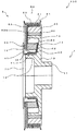
本出願人の先の提案に係るアイソレーションプーリを図3の断面図に基づいて説明する。
図3に示すように、アイソレーションプーリ100は、エンジンのクランクシャフトに装着され、クランクシャフトの捩り振動を低減するダンパ部1と、補機駆動用のプーリを有し、クランクシャフトの回転変動を吸収するアイソレータ部2とを備えている。The isolation pulley according to the applicant's previous proposal will be described based on the cross-sectional view of FIG.
As shown in FIG. 3, the
ダンパ部1は、ハブ10、慣性質量体20及び環状弾性体30から構成されている。
ハブ10は、中心部にエンジンのクランクシャフト(不図示)に取付けられる取付部11と、この取付部11の周縁部近傍から軸方向に延出し、中心軸と同軸状の外周面12を有する内部円筒部13と、この内部円筒部13の端部から放射方向に延出する立上がり部14と、この立上がり部14の周縁部から軸方向に延出し、中心軸と同軸状の外周面を有する外部円筒部15とから構成されている。The
The
慣性質量体20は、円筒状の形状を有し、ハブ10の外部円筒部15と同軸状に配置されており、また、慣性質量体20の内周面とハブ10の外部円筒部15の外周面との間には、加硫ゴム等の環状弾性体30が圧入されている。 The
一方、アイソレータ部2は、アイレーションリング40、プーリ部50及び環状弾性体60から構成されている。
アイレーションリング40は、全体形状がリング状をなし、中心軸と同軸状に配置される円筒状の嵌合部41と、この嵌合部41の端部から放射方向に延出する支持部42とを有しており、嵌合部41には、後述するプレッシャーリングの嵌合部が圧入されて同軸状に嵌合し、嵌合部41の内周面には、プレッシャーリングの嵌合部の外周面が面接合しており、また、支持部42には、ゴム状の環状弾性体60の一端面が接着されている。On the other hand, the
The
プーリ部50は、慣性質量体20と同軸状に配置されており、慣性質量体20の外周面を覆う円筒部51と、慣性質量体20の端面を覆うとともに、環状弾性体60の他端面が固着されるカバー部52とを有する円筒状をなしている。
円筒部51の外周面には、補機駆動用の無端ベルト(不図示)が掛け回されるプーリ溝53,53,…が軸方向に複数本形成されており、また、カバー部52の裏面52bとアイレーションリング40の支持部42との間には、加硫ゴム等からなり、ハブ10側に固定されるアイレーションリング40とプーリ部50との間で捩り変形を受けることによってクランクシャフトの回転変動を吸収する環状弾性体60が軸方向に予圧縮された状態で装着されている。The
On the outer peripheral surface of the cylindrical portion 51, a plurality of pulley grooves 53, 53,... Around which an endless belt (not shown) for driving auxiliary equipment is wound are formed in the axial direction. A crankshaft is formed between the
プレッシャーリング(押圧部材)70は、環状弾性体60に軸方向の予圧縮を付与するためのもので、全体形状がリング状をなし、中心軸と同軸状に配置される円筒状の嵌合部71と、この嵌合部71の端部から放射方向に延出する押圧部72とを有している。
そして、嵌合部71は、アイレーションリング40の嵌合部41に圧入されて同軸状に嵌合し、嵌合部71の外周面は、嵌合部41の内周面に面接合しており、また、嵌合部71は、ハブ10の内部円筒部13の外周面12に面接合しており、この嵌合によって、ダンパ部1とアイソレータ部2とが組付けられて一体化されている。The pressure ring (pressing member) 70 is for applying pre-compression in the axial direction to the annular
The
プレッシャーリング70の押圧部72とプーリ部50のカバー部52との間には、ダンパ部1とアイソレータ部2とがねじれ方向に相対変位する際の押圧部72とカバー部52との摺動抵抗を低減するために、樹脂等からなるスラストベアリング80が配設されている。そして、プレッシャーリング70の押圧部72は、スラストベアリング80を介してプーリ部50のカバー部52を環状弾性体60側へ押圧し、これにより、環状弾性体60に軸方向に予圧縮が付与されている。
また、慣性質量体20の外周面と円筒部51の内周面との間には、樹脂等からなるジャーナルベアリング81が設けられている。Between the pressing part 72 of the
A journal bearing 81 made of resin or the like is provided between the outer peripheral surface of the
しかしながら、プレッシャーリング(押圧部材)の押圧部とプーリ部のカバー部との間に配設されたスラストベアリングは、その表面の摩擦係数は極めて小さいため、上述した従来のアイソレーションプーリにあっては、エンジンが高速回転領域に入り、アイソレーションプーリが高速回転すると、スラストベアリングが遠心力によって径方向に位置ずれを起こす場合があるといった問題点があった。 However, the thrust bearing disposed between the pressing portion of the pressure ring (pressing member) and the cover portion of the pulley portion has a very small coefficient of friction on the surface thereof. When the engine enters the high-speed rotation region and the isolation pulley rotates at a high speed, the thrust bearing may be displaced in the radial direction due to centrifugal force.
そこで、本発明は、上述した課題を解決するために成されたものであり、プレッシャーリング(押圧部材)の押圧部とプーリ部のカバー部との間に配設されたスラストベアリングの位置ずれを防止することができるアイソレーションプーリを提供することを目的とする。 Therefore, the present invention has been made to solve the above-described problems, and it is possible to reduce the displacement of the thrust bearing disposed between the pressing portion of the pressure ring (pressing member) and the cover portion of the pulley portion. An object of the present invention is to provide an isolation pulley that can be prevented.
前記課題を解決するため、請求項1に記載の発明は、慣性質量体を有するダンパ部と、
外周部にプーリ溝が形成され、前記外周部から中心方向に延出するカバー部を有するプーリ部と、
前記ダンパ部と前記カバー部との間に配設された弾性体と、
前記カバー部と対向する押圧部を有し、前記カバー部を軸方向に押圧して前記弾性体に軸方向の予圧縮を付与する押圧部材と、
前記押圧部と前記カバー部との間に配設されたスラストベアリングと、
を備えたアイソレーションプーリにおいて、
前記スラストベアリングと前記カバー部との間に、前記スラストベアリングの径方向の位置ずれを防止する位置ずれ防止手段を設けたことを特徴とする。In order to solve the above-described problem, the invention according to
Pulley grooves formed on the outer peripheral portion, and having a cover portion extending in the center direction from the outer peripheral portion;
An elastic body disposed between the damper portion and the cover portion;
A pressing member that has a pressing part facing the cover part, presses the cover part in the axial direction, and applies axial pre-compression to the elastic body;
A thrust bearing disposed between the pressing portion and the cover portion;
In an isolation pulley with
A misalignment prevention means for preventing misalignment of the thrust bearing in the radial direction is provided between the thrust bearing and the cover portion.
また、請求項2に記載の発明は、請求項1に記載の発明において、前記位置ずれ防止手段は、前記スラストベアリングとの密接面を有する薄肉状のゴム状弾性体からなることを特徴とする。 According to a second aspect of the present invention, in the first aspect of the present invention, the misalignment prevention means comprises a thin rubber-like elastic body having a close contact surface with the thrust bearing. .
また、請求項3に記載の発明は、請求項2に記載の発明において、前記薄肉状のゴム状弾性体は、前記密接面がリング状であることを特徴とする。 According to a third aspect of the present invention, in the second aspect of the present invention, the thin rubber-like elastic body is characterized in that the contact surface has a ring shape.
また、請求項4に記載の発明は、請求項2又は3に記載の発明において、前記薄肉状のゴム状弾性体は、前記カバー部の表面に固着されていることを特徴とする。 The invention according to
また、請求項5に記載の発明は、請求項4に記載の発明において、前記薄肉状のゴム状弾性体は、前記カバー部に前記弾性体と同時に加硫接着されていることを特徴とする。 The invention according to
また、請求項6に記載の発明は、請求項2乃至5のいずれか一に記載の発明において、前記薄肉状のゴム状弾性体には、前記スラストベアリングを組み付ける際の位置合わせ部が設けられていることを特徴とする。 According to a sixth aspect of the present invention, in the invention according to any one of the second to fifth aspects, the thin rubber-like elastic body is provided with an alignment portion for assembling the thrust bearing. It is characterized by.
また、請求項7に記載の発明は、請求項6に記載の発明において、前記位置合わせ部は、前記スラストベアリングの外周側に全周にわたって設けられていることを特徴とする。 The invention according to
また、請求項8に記載の発明は、慣性質量体を有するダンパ部と、
外周部にプーリ溝が形成され、前記外周部から中心方向に延出するカバー部を有するプーリ部と、
前記ダンパ部と前記カバー部との間に配設された弾性体と、
前記カバー部と対向する押圧部を有し、前記カバー部を軸方向に押圧して前記弾性体に軸方向の予圧縮を付与する押圧部材と、
前記押圧部と前記カバー部との間に配設されたスラストベアリングと、
を備えたアイソレーションプーリにおいて、
前記スラストベアリングと前記押圧部との間に、前記スラストベアリングの径方向の位置ずれを防止する位置ずれ防止手段を設けたことを特徴とする。The invention according to
Pulley grooves formed on the outer peripheral portion, and having a cover portion extending in the center direction from the outer peripheral portion;
An elastic body disposed between the damper portion and the cover portion;
A pressing member that has a pressing part facing the cover part, presses the cover part in the axial direction, and applies axial pre-compression to the elastic body;
A thrust bearing disposed between the pressing portion and the cover portion;
In an isolation pulley with
A misalignment prevention means for preventing misalignment in the radial direction of the thrust bearing is provided between the thrust bearing and the pressing portion.
また、請求項9に記載の発明は、請求項8に記載の発明において、前記位置ずれ防止手段は、前記スラストベアリングとの密接面を有する薄肉状のゴム状弾性体がらなることを特徴とする。 The invention according to
また、請求項10に記載の発明は、請求項9に記載の発明において、前記薄肉状のゴム状弾性体は、前記密接面がリング状であることを特徴とする。 According to a tenth aspect of the present invention, in the invention according to the ninth aspect, the thin rubber-like elastic body is characterized in that the contact surface has a ring shape.
さらに、請求項11に記載の発明は、請求項9又は10に記載の発明において、前記薄肉状のゴム状弾性体は、前記押圧部に固定されていることを特徴とする。 Furthermore, an invention described in claim 11 is the invention described in
そして、請求項12に記載の発明は、請求項9乃至11のいずれか一に記載の発明において、前記薄肉状のゴム状弾性体には、前記押圧部の外縁部と前記カバー部との隙間を塞ぐカバーが設けられていることを特徴とする。 A twelfth aspect of the present invention is the invention according to any one of the ninth to eleventh aspects, wherein the thin rubber-like elastic body includes a gap between an outer edge portion of the pressing portion and the cover portion. A cover is provided to close the door.
請求項1に記載の発明によれば、スラストベアリングとプーリ部のカバー部との間に、スラストベアリングの径方向の位置ずれを防止する位置ずれ防止手段を設けたため、エンジンが高速回転領域に入り、アイソレーションプーリが高速回転しても、スラストベアリングが遠心力によって径方向に位置ずれを起こすことがない。 According to the first aspect of the present invention, since the displacement preventing means for preventing the radial displacement of the thrust bearing is provided between the thrust bearing and the cover portion of the pulley portion, the engine enters the high speed rotation region. Even if the isolation pulley rotates at a high speed, the thrust bearing does not cause radial displacement due to centrifugal force.
また、請求項2に記載の発明によれば、位置ずれ防止手段がスラストベアリングとの密接面を有する薄肉状のゴム状弾性体からなるため、スラストベアリングの位置ずれ防止効果に加え、押圧部材の押圧部とプーリ部のカバー部との平行度の精度が若干低い場合であっても、押圧部をプーリ部のカバー部側に押し込めば、スラストベアリングを介して薄肉状のゴム状弾性体が圧縮弾性変形するため、押圧部又はカバー部とスラストベアリングとの平行出しが容易に可能となる。
また、スラストベアリングとプーリ部のカバー部との間にゴム状弾性体が介在するため、スラストベアリングと押圧部材の押圧部との密着性が向上する。According to the second aspect of the present invention, since the displacement prevention means is made of a thin rubber-like elastic body having a close contact surface with the thrust bearing, in addition to the displacement prevention effect of the thrust bearing, Even if the accuracy of the parallelism between the pressing part and the cover part of the pulley part is slightly low, if the pressing part is pushed into the cover part side of the pulley part, the thin rubber-like elastic body is compressed via the thrust bearing. Due to the elastic deformation, the pressing part or the cover part and the thrust bearing can be easily parallelized.
Further, since the rubber-like elastic body is interposed between the thrust bearing and the cover portion of the pulley portion, the adhesion between the thrust bearing and the pressing portion of the pressing member is improved.
また、請求項3に記載の発明によれば、薄肉状のゴム状弾性体は、スラストベアリングとの密接面がリング状であり、プーリ部のカバー部のスラストベアリングとの当たり面は、薄肉状のゴム状弾性体で覆われるため、カバー部の表面の表面粗さ度合を緩和することができる。 According to the invention described in
また、請求項4に記載の発明によれば、薄肉状のゴム状弾性体は、プーリ部のカバー部の表面に固着されているため、スラストベアリングを組み付ける際に、薄肉状のゴム状弾性体に位置ずれ等が生じることがなく、スラストベアリングの組み付けが容易となる。 According to the invention described in
また、請求項5に記載の発明によれば、薄肉状のゴム状弾性体は、プーリ部のカバー部に弾性体と同時に加硫接着されているため、次の効果が得られる。
すなわち、従来、カバー部の裏面に弾性体を加硫接着する工程でカバー部の表面にゴムバリが付着する場合があり、このような場合には、ゴムバリの除去作業が必要であったが、請求項5に記載の発明によれば、カバー部の表面に薄肉状のゴム状弾性体を加硫接着する構成としたため、従来のようなゴムバリが付着することがなく、その除去作業も不要となる。According to the invention described in
That is, conventionally, a rubber burr may adhere to the surface of the cover part in the process of vulcanizing and bonding the elastic body to the back surface of the cover part. In such a case, a work for removing the rubber burr has been required. According to the invention described in
また、請求項6に記載の発明によれば、薄肉状のゴム状弾性体には、スラストベアリングを組み付ける際の位置合わせ部が設けられているため、カバー部の表面のスラストベアリングを組み付ける際の位置合わせが容易になる。 According to the invention described in
また、請求項7に記載の発明によれば、薄肉状のゴム状弾性体に設けられた位置合わせ部は、スラストベアリングの外周側に全周にわたって設けられていため、プーリ部のカバー部とスラストベアリングとの隙間にダスト等が侵入するのを防止することができる。 According to the seventh aspect of the present invention, since the alignment portion provided in the thin rubber-like elastic body is provided on the outer peripheral side of the thrust bearing over the entire circumference, the cover portion of the pulley portion and the thrust portion are provided. It is possible to prevent dust and the like from entering the gap with the bearing.
また、請求項8に記載の発明によれば、スラストベアリングと押圧部材の押圧部との間に、スラストベアリングの径方向の位置ずれを防止する位置ずれ防止手段を設けたため、エンジンが高速回転領域に入り、アイソレーションプーリが高速回転しても、スラストベアリングが遠心力によって径方向に位置ずれを起こすことがない。 According to the invention described in
また、請求項9に記載の発明によれば、位置ずれ防止手段がスラストベアリングとの密接面を有する薄肉状のゴム状弾性体からなるため、スラストベアリングの位置ずれ防止効果に加え、押圧部材の押圧部とプーリ部のカバー部との平行度の精度が若干低い場合であっても、押圧部をプーリ部のカバー部側に押し込めば、薄肉状のゴム状弾性体が圧縮弾性変形するため、押圧部又はカバー部とスラストベアリングとの平行出しが容易に可能となる。
また、スラストベアリングと押圧部材の押圧部との間にゴム状弾性体が介在するため、スラストベアリングとプーリ部のカバー部との密着性が向上する。According to the ninth aspect of the invention, since the displacement prevention means is made of a thin rubber-like elastic body having a close contact surface with the thrust bearing, in addition to the effect of preventing the displacement of the thrust bearing, Even if the accuracy of the parallelism between the pressing part and the cover part of the pulley part is slightly low, if the pressing part is pushed into the cover part side of the pulley part, the thin rubber-like elastic body will be compressed and elastically deformed. The pressing part or the cover part and the thrust bearing can be easily parallelized.
Moreover, since the rubber-like elastic body is interposed between the thrust bearing and the pressing portion of the pressing member, the adhesion between the thrust bearing and the cover portion of the pulley portion is improved.
また、請求項10に記載の発明によれば、薄肉状のゴム状弾性体は、スラストベアリングとの密接面がリング状であり、押圧部材の押圧部のスラストベアリングとの当たり面は、薄肉状のゴム状弾性体で覆われるため、押圧部の裏面の表面粗さ度合を緩和することができる。 According to the invention of
さらに、請求項11に記載の発明によれば、薄肉状のゴム状弾性体は、押圧部材の押圧部に固定されているため、押圧部材の組み付けの際に、薄肉状のゴム状弾性体に位置ずれ等が生じることがなく、押圧部材の組み付けが容易となる。 Furthermore, according to the invention described in claim 11, since the thin rubber elastic body is fixed to the pressing portion of the pressing member, the thin rubber elastic body is attached to the thin rubber elastic body when the pressing member is assembled. Misalignment or the like does not occur, and the pressing member can be easily assembled.
そして、請求項12に記載の発明によれば、薄肉状のゴム状弾性体には、押圧部材の押圧部の外縁部とプーリ部のカバー部との隙間を塞ぐカバーが設けられているため、押圧部材の押圧部とスラストベアリングとの隙間にダスト等が侵入するのを防止することができる。 According to the invention of
以下、本発明の実施の形態を添付図面に基づいて説明する。
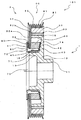
図1は本発明の第1の実施の形態に係るアイソレーションプーリの断面図である。尚、図1において、図3と同一の構成には同一の符合を付してその説明を省略する。Hereinafter, embodiments of the present invention will be described with reference to the accompanying drawings.
FIG. 1 is a cross-sectional view of an isolation pulley according to a first embodiment of the present invention. In FIG. 1, the same components as those in FIG. 3 are denoted by the same reference numerals, and the description thereof is omitted.
図1に示すように、本実施の形態に係るアイソレーションプーリ101にあっては、プーリ部50のカバー部52の表面52aとスラストベアリング80との間に、その摩擦力でスラストベアリング80の径方向の位置ずれを防止する薄肉状のゴム状弾性体(位置ずれを防止手段)90が設けられている。 As shown in FIG. 1, in the
このゴム状弾性体90は、スラストベアリング80との密接面91が中心軸(図中の1点破線)を略中心としたリング状をなしており、カバー部52に環状弾性体60と同時に加硫接着されている。また、ゴム状弾性体90の一部は、カバー部52の開口部を介して環状弾性体60の一部と一体化されている。
ゴム状弾性体90において、スラストベアリング80の外周側には、スラストベアリング80を組み付ける際に位置決めとなる段差状の位置合わせ部92が設けられている。The rubber-like
In the rubber-like
スラストベアリング80は、押圧部72からの押圧力を受けてゴム状弾性体90の密接面91に密接してプーリ部2と一体になって回転するが、スラストベアリング80の押圧部72側の摺動面が押圧部72の裏面と低摩擦で摺動するため、ダンパ部1とアイソレータ部2とのねじれ方向の相対変位は、従来のアイソレーションプーリと同様に何ら支障なく行われる。 The
このように、アイソレーションプーリ101によれば、スラストベアリング80とカバー部52との間に、スラストベアリング80の径方向の位置ずれを防止するゴム状弾性体90を設けたため、エンジンが高速回転領域に入り、アイソレーションプーリ101が高速回転しても、ゴム状弾性体90の密接面91の摩擦力により、スラストベアリング80が遠心力によって径方向に位置ずれを起こすことがない。 As described above, according to the
また、カバー部52の表面52aにゴム状弾性体90を設けたため、押圧部材70の押圧部72とプーリ部2のカバー部52との平行度の精度が若干低い場合であっても、押圧部72をカバー部52側に押し込めば、スラストベアリング80を介してゴム状弾性体90が圧縮弾性変形するため、押圧部72又はカバー部52とスラストベアリング80との平行出しが容易に可能となる。また、スラストベアリング80とカバー部52との間にゴム状弾性体90が介在するため、押圧部材70の押圧部72とプーリ部50のカバー部52との密着性が向上する。 Further, since the rubber-like
また、ゴム状弾性体90は、スラストベアリング80との密接面91がリング状であり、カバー部52のスラストベアリング80との当たり面は、ゴム状弾性体90で覆われるため、カバー部52の表面52aに面粗さがあっても、スラストベアリング80が磨耗や損傷を受けることがなく、カバー部52の表面52aの表面粗さ度合を緩和することができる。 Further, the rubber-like
また、ゴム状弾性体90は、カバー部52の表面52aに加硫接着されているため、スラストベアリング80を組み付ける際に、ゴム状弾性体90に位置ずれ等が生じることがなく、スラストベアリング80の組み付けが容易となる。 Further, since the rubber-like
また、ゴム状弾性体90は、カバー部52に環状弾性体60と同時に加硫接着されているため、次の効果が得られる。
すなわち、従来、カバー部52の裏面52bに環状弾性体60を加硫接着する工程でカバー部52の表面52aにゴムバリが付着する場合があり、このような場合には、ゴムバリの除去作業が必要であったが、本実施の形態に係るアイソレーションプーリ101によれば、カバー部52の表面52aにゴム状弾性体90を加硫接着する構成としたため、従来のようなゴムバリが付着することがなく、その除去作業も不要となる。Further, since the rubber-like
That is, conventionally, rubber burrs may adhere to the surface 52a of the
また、ゴム状弾性体90には、スラストベアリング80を組み付ける際の位置合わせ部92が設けられているため、カバー部52の表面52aのスラストベアリング80を組み付ける際の位置合わせが容易になる。 Further, since the rubber-like
また、ゴム状弾性体90に設けられた段差状の位置合わせ部92は、スラストベアリング80の外周側に全周にわたって設けられていため、カバー部52とスラストベアリング80との隙間にダスト等が侵入するのを防止することができる。 Further, the step-like alignment portion 92 provided in the rubber-like
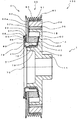
次に本発明の第2の実施の形態を図2に基づいて説明する。
図2は第2の実施の形態に係るアイソレーションプーリの断面図である。尚、図2において、図3と同一の構成には同一の符合を付してその説明を省略する。
図2に示すように、本実施の形態に係るアイソレーションプーリ102にあっては、押圧部材70の押圧部72とスラストベアリング80との間に、その摩擦力でスラストベアリング80の径方向の位置ずれを防止する薄肉状のゴム状弾性体(位置ずれを防止手段)95が設けられている。Next, a second embodiment of the present invention will be described with reference to FIG.
FIG. 2 is a cross-sectional view of an isolation pulley according to the second embodiment. In FIG. 2, the same components as those in FIG.
As shown in FIG. 2, in the isolation pulley 102 according to the present embodiment, the radial position of the thrust bearing 80 between the pressing portion 72 of the pressing
このゴム状弾性体95は、スラストベアリング80との密接面96が中心軸(図中の1点破線)を略中心としたリング状をなしており、その嵌合部97が押圧部72の外縁に嵌合した状態で、押圧部72に固定されている。
また、ゴム状弾性体95において、スラストベアリング80の外周側には、スラストベアリング80の位置合わせを容易にするための段差状の位置合わせ部98が設けられている。
また、位置合わせ部98の外縁側には、その先端部がカバー部52の表面52aに密接摺動するカバー99が周方向にわたって設けられている。The rubber-like elastic body 95 has a ring shape in which the contact surface 96 with the
In the rubber-like elastic body 95, a step-
Further, on the outer edge side of the
スラストベアリング80は、押圧部72からの押圧力を受けてゴム状弾性体95の密接面96に密接してダンパ部1と一体になって回転するが、スラストベアリング80のカバー部52側の摺動面がカバー部52の表面52aと低摩擦で摺動するため、ダンパ部1とアイソレータ部2とのねじれ方向の相対変位は、従来のアイソレーションプーリと同様に何らの支障もなく行われる。 The
このように、アイソレーションプーリ102によれば、スラストベアリング80と押圧部材70の押圧部72との間に、スラストベアリング80の径方向の位置ずれを防止するゴム状弾性体95を設けたため、エンジンが高速回転領域に入り、アイソレーションプーリ102が高速回転しても、スラストベアリング80が遠心力によって径方向に位置ずれを起こすことがない。 Thus, according to the isolation pulley 102, the rubber-like elastic body 95 that prevents the radial displacement of the
また、押圧部材70の押圧部72にゴム状弾性体95を設けたため、押圧部材70の押圧部72とプーリ部2のカバー部52との平行度の精度が若干低い場合であっても、押圧部70をプーリ部2のカバー部52側に押し込めば、ゴム状弾性体95が圧縮弾性変形するため、押圧部72又はカバー部52とスラストベアリング80との平行出しが容易に可能となる。 Further, since the rubber-like elastic body 95 is provided in the pressing portion 72 of the pressing
また、ゴム状弾性体95は、スラストベアリング80との密接面96がリング状であり、押圧部72のスラストベアリング80との当たり面は、ゴム状弾性体95で覆われるため、押圧部72の裏面に面粗さがあっても、スラストベアリング80が磨耗や損傷を受けることがなく、押圧部72の裏面の表面粗さ度合を緩和することができる。
また、スラストベアリング80と押圧部材70の押圧部72との間にゴム状弾性体95が介在するため、スラストベアリング80とプーリ部50のカバー部52との密着性が向上する。The rubber-like elastic body 95 has a ring-shaped contact surface 96 with the
Further, since the rubber-like elastic body 95 is interposed between the
また、ゴム状弾性体95は、押圧部72に固定されているため、スラストベアリング80を組み付ける際に、ゴム状弾性体95に位置ずれ等が生じることがなく、スラストベアリング80の組み付けが容易となる。 In addition, since the rubber-like elastic body 95 is fixed to the pressing portion 72, when the
また、ゴム状弾性体95には、スラストベアリング80を組み付ける際の位置合わせ部98が設けられているため、スラストベアリング80を組み付ける際の位置合わせが容易になる。 Further, since the rubber-like elastic body 95 is provided with the
また、ゴム状弾性体95に設けられた段差状の位置合わせ部98は、スラストベアリング80の外周側に全周にわたって設けられていため、押圧部72とスラストベアリング80との隙間にダスト等が侵入するのを防止することができる。
また、位置合わせ部98の外縁側には、その先端部がカバー部52の表面52aに密接摺動するカバー99が周方向にわたって設けられているため、カバー部52とスラストベアリング80との隙間にダスト等が侵入するのを防止することができる。Further, the step-
Further, since a cover 99 whose tip end is in close contact with the surface 52a of the
尚、上述した第1及び第2の実施の形態にあっては、環状弾性体60を軸方向に予圧縮するためのプレッシャーリング70の嵌合部71が、ハブ10の内部円筒部13に嵌合してダンパ部1とアイソレータ部2とが組付けられて一体化するものを例示したが、本発明は、上記の嵌合タイプに限定されるものではなく、例えば、プレッシャーリングの一部をハブ側に溶接等によって固着して、ダンパ部1とアイソレータ部2とをねじれ方向に相対変位可能に一体化するタイプのものにあっても適用可能である。 In the first and second embodiments described above, the
また、ゴム状弾性体90(95)に設けた位置合わせ部92(98)は必ずしも必須の構成ではなく、また、第2の実施の形態におけるカバー99も必ずしも必須の構成ではない。
さらに、第2の実施の形態にあっては、ゴム状弾性体95は、嵌合部97が押圧部72の外縁に嵌合した状態で、押圧部72に固定されているものを例示したが、このような嵌合部97を設けずに、ゴム状弾性体95が押圧部72に加硫接着等により固着したものであってもよい。Further, the alignment portion 92 (98) provided on the rubber-like elastic body 90 (95) is not necessarily an essential configuration, and the cover 99 in the second embodiment is not necessarily an essential configuration.
Furthermore, in the second embodiment, the rubber-like elastic body 95 is illustrated as being fixed to the pressing portion 72 in a state where the
101,102 アイソレーションプーリ
1 ダンパ部
2 アイソレータ部
20 慣性質量体
50 プーリ部
52 カバー部
53 プーリ溝
60 環状弾性体
70 プレッシャーリング(押圧部材)
72 押圧部
80 スラストベアリング
90,95 ゴム状弾性体(位置ずれ防止手段)
91,96 密接面
92,98 位置合わせ部
99 カバーDESCRIPTION OF SYMBOLS 101,102
72
91, 96
Claims (12)
外周部にプーリ溝が形成され、前記外周部から中心方向に延出するカバー部を有するプーリ部と、
前記ダンパ部と前記カバー部との間に配設された弾性体と、
前記カバー部と対向する押圧部を有し、前記カバー部を軸方向に押圧して前記弾性体に軸方向の予圧縮を付与する押圧部材と、
前記押圧部と前記カバー部との間に配設されたスラストベアリングと、
を備えたアイソレーションプーリにおいて、
前記スラストベアリングと前記カバー部との間に、前記スラストベアリングの径方向の位置ずれを防止する位置ずれ防止手段を設けたことを特徴とするアイソレーションプーリ。A damper portion having an inertial mass;
Pulley groove formed on the outer peripheral part, and having a cover part extending in the center direction from the outer peripheral part,
An elastic body disposed between the damper portion and the cover portion;
A pressing member that has a pressing part facing the cover part, presses the cover part in the axial direction, and applies axial pre-compression to the elastic body;
A thrust bearing disposed between the pressing portion and the cover portion;
In an isolation pulley with
An isolation pulley comprising a displacement prevention means for preventing a displacement of the thrust bearing in a radial direction between the thrust bearing and the cover portion.
外周部にプーリ溝が形成され、前記外周部から中心方向に延出するカバー部を有するプーリ部と、
前記ダンパ部と前記カバー部との間に配設された弾性体と、
前記カバー部と対向する押圧部を有し、前記カバー部を軸方向に押圧して前記弾性体に軸方向の予圧縮を付与する押圧部材と、
前記押圧部と前記カバー部との間に配設されたスラストベアリングと、
を備えたアイソレーションプーリにおいて、
前記スラストベアリングと前記押圧部との間に、前記スラストベアリングの径方向の位置ずれを防止する位置ずれ防止手段を設けたことを特徴とするアイソレーションプーリ。A damper portion having an inertial mass;
Pulley groove formed on the outer peripheral part, and having a cover part extending in the center direction from the outer peripheral part,
An elastic body disposed between the damper portion and the cover portion;
A pressing member that has a pressing part facing the cover part, presses the cover part in the axial direction, and applies axial pre-compression to the elastic body;
A thrust bearing disposed between the pressing portion and the cover portion;
In an isolation pulley with
An isolation pulley comprising a displacement prevention means for preventing a displacement of the thrust bearing in the radial direction between the thrust bearing and the pressing portion.
Priority Applications (1)
| Application Number | Priority Date | Filing Date | Title |
|---|---|---|---|
| JP2004144202A JP4389106B2 (en) | 2004-04-12 | 2004-04-12 | Isolation pulley |
Applications Claiming Priority (1)
| Application Number | Priority Date | Filing Date | Title |
|---|---|---|---|
| JP2004144202A JP4389106B2 (en) | 2004-04-12 | 2004-04-12 | Isolation pulley |
Publications (2)
| Publication Number | Publication Date |
|---|---|
| JP2005299909A true JP2005299909A (en) | 2005-10-27 |
| JP4389106B2 JP4389106B2 (en) | 2009-12-24 |
Family
ID=35331672
Family Applications (1)
| Application Number | Title | Priority Date | Filing Date |
|---|---|---|---|
| JP2004144202A Expired - Fee Related JP4389106B2 (en) | 2004-04-12 | 2004-04-12 | Isolation pulley |
Country Status (1)
| Country | Link |
|---|---|
| JP (1) | JP4389106B2 (en) |
Cited By (7)
| Publication number | Priority date | Publication date | Assignee | Title |
|---|---|---|---|---|
| JP2007132360A (en) * | 2005-11-08 | 2007-05-31 | Fukoku Co Ltd | Pulley with damper and manufacturing method thereof |
| JP2008057553A (en) * | 2006-08-29 | 2008-03-13 | Fukoku Co Ltd | Pulley with damper |
| JP2010077996A (en) * | 2008-09-24 | 2010-04-08 | Fukoku Co Ltd | Pulley with damper |
| JP2011033073A (en) * | 2009-07-30 | 2011-02-17 | Fukoku Co Ltd | Pulley with damper |
| US8038554B2 (en) * | 2003-07-11 | 2011-10-18 | Fukoku Co., Ltd. | Isolation damper pulley and method of producing the same |
| JP2014211225A (en) * | 2013-04-22 | 2014-11-13 | Nok株式会社 | Torque fluctuation absorbing damper |
| WO2018095473A1 (en) * | 2016-11-23 | 2018-05-31 | Schaeffler Technologies AG & Co. KG | Torque transmission device and method for producing a torque transmission device |
-
2004
- 2004-04-12 JP JP2004144202A patent/JP4389106B2/en not_active Expired - Fee Related
Cited By (7)
| Publication number | Priority date | Publication date | Assignee | Title |
|---|---|---|---|---|
| US8038554B2 (en) * | 2003-07-11 | 2011-10-18 | Fukoku Co., Ltd. | Isolation damper pulley and method of producing the same |
| JP2007132360A (en) * | 2005-11-08 | 2007-05-31 | Fukoku Co Ltd | Pulley with damper and manufacturing method thereof |
| JP2008057553A (en) * | 2006-08-29 | 2008-03-13 | Fukoku Co Ltd | Pulley with damper |
| JP2010077996A (en) * | 2008-09-24 | 2010-04-08 | Fukoku Co Ltd | Pulley with damper |
| JP2011033073A (en) * | 2009-07-30 | 2011-02-17 | Fukoku Co Ltd | Pulley with damper |
| JP2014211225A (en) * | 2013-04-22 | 2014-11-13 | Nok株式会社 | Torque fluctuation absorbing damper |
| WO2018095473A1 (en) * | 2016-11-23 | 2018-05-31 | Schaeffler Technologies AG & Co. KG | Torque transmission device and method for producing a torque transmission device |
Also Published As
| Publication number | Publication date |
|---|---|
| JP4389106B2 (en) | 2009-12-24 |
Similar Documents
| Publication | Publication Date | Title |
|---|---|---|
| JP4391990B2 (en) | Isolation damper pulley and manufacturing method thereof | |
| US5370581A (en) | Torsion damping device, especially for a motor vehicle | |
| JP4389106B2 (en) | Isolation pulley | |
| JPH0642588A (en) | Tortion damper for automobile | |
| JP2013036530A (en) | Rotation variation absorbing crank pulley | |
| JP4232620B2 (en) | Isolation pulley | |
| JP2007278417A (en) | Damper and isolation damper pulley | |
| JP5945496B2 (en) | Pulley with damper | |
| JP5594464B2 (en) | Torque fluctuation absorbing damper | |
| JP3531685B2 (en) | Torque fluctuation absorption damper | |
| JP4732983B2 (en) | Pulley with damper | |
| JP4314561B2 (en) | Isolation damper pulley | |
| JP5039467B2 (en) | Pulley with damper | |
| JP4904781B2 (en) | Pulley with damper and manufacturing method thereof | |
| JP3994278B2 (en) | Torque fluctuation absorbing damper | |
| JP4632792B2 (en) | Pulley with damper function | |
| JPH1182630A (en) | Torque transmission device | |
| JP4479903B2 (en) | Torque fluctuation absorbing damper | |
| JP6607080B2 (en) | Pulley | |
| JP7821064B2 (en) | shaft structure | |
| JP2002295588A (en) | Torsional damper | |
| JP2006194265A (en) | Torque fluctuation absorbing damper | |
| JP5409169B2 (en) | Pulley with damper | |
| JP6280345B2 (en) | Rotation fluctuation absorbing damper | |
| JP4862538B2 (en) | Damper pulley |
Legal Events
| Date | Code | Title | Description |
|---|---|---|---|
| A621 | Written request for application examination |
Free format text: JAPANESE INTERMEDIATE CODE: A621 Effective date: 20061208 |
|
| A977 | Report on retrieval |
Free format text: JAPANESE INTERMEDIATE CODE: A971007 Effective date: 20081201 |
|
| A131 | Notification of reasons for refusal |
Free format text: JAPANESE INTERMEDIATE CODE: A131 Effective date: 20090512 |
|
| A521 | Written amendment |
Free format text: JAPANESE INTERMEDIATE CODE: A523 Effective date: 20090707 |
|
| TRDD | Decision of grant or rejection written | ||
| A01 | Written decision to grant a patent or to grant a registration (utility model) |
Free format text: JAPANESE INTERMEDIATE CODE: A01 Effective date: 20090825 |
|
| A01 | Written decision to grant a patent or to grant a registration (utility model) |
Free format text: JAPANESE INTERMEDIATE CODE: A01 |
|
| A61 | First payment of annual fees (during grant procedure) |
Free format text: JAPANESE INTERMEDIATE CODE: A61 Effective date: 20090918 |
|
| FPAY | Renewal fee payment (event date is renewal date of database) |
Free format text: PAYMENT UNTIL: 20121016 Year of fee payment: 3 |
|
| R150 | Certificate of patent or registration of utility model |
Ref document number: 4389106 Country of ref document: JP Free format text: JAPANESE INTERMEDIATE CODE: R150 Free format text: JAPANESE INTERMEDIATE CODE: R150 |
|
| FPAY | Renewal fee payment (event date is renewal date of database) |
Free format text: PAYMENT UNTIL: 20151016 Year of fee payment: 6 |
|
| R250 | Receipt of annual fees |
Free format text: JAPANESE INTERMEDIATE CODE: R250 |
|
| R250 | Receipt of annual fees |
Free format text: JAPANESE INTERMEDIATE CODE: R250 |
|
| R250 | Receipt of annual fees |
Free format text: JAPANESE INTERMEDIATE CODE: R250 |
|
| R250 | Receipt of annual fees |
Free format text: JAPANESE INTERMEDIATE CODE: R250 |
|
| R250 | Receipt of annual fees |
Free format text: JAPANESE INTERMEDIATE CODE: R250 |
|
| LAPS | Cancellation because of no payment of annual fees |