JP4391990B2 - Isolation damper pulley and manufacturing method thereof - Google Patents
Isolation damper pulley and manufacturing method thereof Download PDFInfo
- Publication number
- JP4391990B2 JP4391990B2 JP2005511591A JP2005511591A JP4391990B2 JP 4391990 B2 JP4391990 B2 JP 4391990B2 JP 2005511591 A JP2005511591 A JP 2005511591A JP 2005511591 A JP2005511591 A JP 2005511591A JP 4391990 B2 JP4391990 B2 JP 4391990B2
- Authority
- JP
- Japan
- Prior art keywords
- fitting portion
- fitting
- pulley
- fitted
- axial direction
- Prior art date
- Legal status (The legal status is an assumption and is not a legal conclusion. Google has not performed a legal analysis and makes no representation as to the accuracy of the status listed.)
- Expired - Fee Related
Links
- 238000002955 isolation Methods 0.000 title claims abstract description 115
- 238000004519 manufacturing process Methods 0.000 title claims description 10
- 238000003825 pressing Methods 0.000 claims abstract description 55
- 230000006835 compression Effects 0.000 claims abstract description 8
- 238000007906 compression Methods 0.000 claims abstract description 8
- 230000002093 peripheral effect Effects 0.000 claims description 34
- 238000000926 separation method Methods 0.000 claims description 16
- 238000000034 method Methods 0.000 claims description 15
- 238000003466 welding Methods 0.000 description 9
- 239000002184 metal Substances 0.000 description 6
- 239000000463 material Substances 0.000 description 4
- 239000004636 vulcanized rubber Substances 0.000 description 4
- 230000004323 axial length Effects 0.000 description 2
- 230000000903 blocking effect Effects 0.000 description 2
- 239000013013 elastic material Substances 0.000 description 2
- 238000005516 engineering process Methods 0.000 description 2
- 238000005304 joining Methods 0.000 description 2
- 238000002360 preparation method Methods 0.000 description 2
- 239000011347 resin Substances 0.000 description 2
- 229920005989 resin Polymers 0.000 description 2
- 238000005452 bending Methods 0.000 description 1
- 230000005540 biological transmission Effects 0.000 description 1
- 238000005266 casting Methods 0.000 description 1
- 238000005520 cutting process Methods 0.000 description 1
- 230000000694 effects Effects 0.000 description 1
- 238000005096 rolling process Methods 0.000 description 1
Images


Classifications
-
- F—MECHANICAL ENGINEERING; LIGHTING; HEATING; WEAPONS; BLASTING
- F16—ENGINEERING ELEMENTS AND UNITS; GENERAL MEASURES FOR PRODUCING AND MAINTAINING EFFECTIVE FUNCTIONING OF MACHINES OR INSTALLATIONS; THERMAL INSULATION IN GENERAL
- F16F—SPRINGS; SHOCK-ABSORBERS; MEANS FOR DAMPING VIBRATION
- F16F15/00—Suppression of vibrations in systems; Means or arrangements for avoiding or reducing out-of-balance forces, e.g. due to motion
- F16F15/10—Suppression of vibrations in rotating systems by making use of members moving with the system
- F16F15/12—Suppression of vibrations in rotating systems by making use of members moving with the system using elastic members or friction-damping members, e.g. between a rotating shaft and a gyratory mass mounted thereon
- F16F15/121—Suppression of vibrations in rotating systems by making use of members moving with the system using elastic members or friction-damping members, e.g. between a rotating shaft and a gyratory mass mounted thereon using springs as elastic members, e.g. metallic springs
- F16F15/124—Elastomeric springs
- F16F15/126—Elastomeric springs consisting of at least one annular element surrounding the axis of rotation
-
- F—MECHANICAL ENGINEERING; LIGHTING; HEATING; WEAPONS; BLASTING
- F16—ENGINEERING ELEMENTS AND UNITS; GENERAL MEASURES FOR PRODUCING AND MAINTAINING EFFECTIVE FUNCTIONING OF MACHINES OR INSTALLATIONS; THERMAL INSULATION IN GENERAL
- F16F—SPRINGS; SHOCK-ABSORBERS; MEANS FOR DAMPING VIBRATION
- F16F15/00—Suppression of vibrations in systems; Means or arrangements for avoiding or reducing out-of-balance forces, e.g. due to motion
- F16F15/10—Suppression of vibrations in rotating systems by making use of members moving with the system
- F16F15/14—Suppression of vibrations in rotating systems by making use of members moving with the system using masses freely rotating with the system, i.e. uninvolved in transmitting driveline torque, e.g. rotative dynamic dampers
- F16F15/1407—Suppression of vibrations in rotating systems by making use of members moving with the system using masses freely rotating with the system, i.e. uninvolved in transmitting driveline torque, e.g. rotative dynamic dampers the rotation being limited with respect to the driving means
- F16F15/1414—Masses driven by elastic elements
- F16F15/1435—Elastomeric springs, i.e. made of plastic or rubber
- F16F15/1442—Elastomeric springs, i.e. made of plastic or rubber with a single mass
-
- F—MECHANICAL ENGINEERING; LIGHTING; HEATING; WEAPONS; BLASTING
- F16—ENGINEERING ELEMENTS AND UNITS; GENERAL MEASURES FOR PRODUCING AND MAINTAINING EFFECTIVE FUNCTIONING OF MACHINES OR INSTALLATIONS; THERMAL INSULATION IN GENERAL
- F16H—GEARING
- F16H55/00—Elements with teeth or friction surfaces for conveying motion; Worms, pulleys or sheaves for gearing mechanisms
- F16H55/32—Friction members
- F16H55/36—Pulleys
- F16H2055/366—Pulleys with means providing resilience or vibration damping
Landscapes
- Engineering & Computer Science (AREA)
- General Engineering & Computer Science (AREA)
- Mechanical Engineering (AREA)
- Physics & Mathematics (AREA)
- Acoustics & Sound (AREA)
- Aviation & Aerospace Engineering (AREA)
- Pulleys (AREA)
- Forging (AREA)
- Extrusion Moulding Of Plastics Or The Like (AREA)
Abstract
Description
【0001】
【技術分野】
本発明は、エンジンのクランクシャフトに装着され、クランクシャフトのトルクを無端ベルトを介して各種の補機へ伝達するアイソレーション・ダンパプーリの技術に関し、主としてアイドリング回転時のようにエンジン低回転時におけるエンジンのトルク変動によって発生するクランクシャフトの速度変動を遮断するとともに、クランクシャフトの捩り振動を低減するアイソレーション・ダンパプーリの技術に関するものである。
【0002】
【背景技術】
アイソレーション・ダンパプーリは、たとえば、特開2001−159448号公報に記載されるように、クランクシャフトに装着されるダンパ部とこのダンパ部に組み付けられるアイソレーションプーリ部とを有している。ダンパ部はクランクシャフトに装着されるハブと、このハブの円筒部に環状弾性体を介して取り付けられる環状質量体とを有している。アイソレーションプーリ部は外周面にプーリ溝が形成された円筒部およびこの円筒部の一端部から中心方向に延出するカバー部からなるプーリ部と、カバー部に一端部が固定される環状弾性体とを有しており、環状弾性体の他端部は支持部材を介してハブに固定されるようになっている。
【0003】
【発明の開示】
【0004】
【発明が解決しようとする課題】
図5は、従来のアイソレーション・ダンパプーリの一部を示す断面図であり、このアイソレーション・ダンパプーリは、ダンパ部41とアイソレーションプーリ部42とを有している。ダンパ部41は、クランクシャフトに装着されるハブ43と、ハブ43の外周に環状弾性体44を介して固定される環状質量体45とを備え、クランクシャフトの捩り振動を低減する機能を有するものである。ハブ43は、一般に板金をプレス加工することにより成形されており、中央部にクランクシャフトの先端部が貫通する貫通孔46が形成された円盤部47と、この円盤部47の周縁部から軸方向に延出する円筒部48とから構成されている。環状質量体45は小径部45aおよび大径部45bを有し全体的に環状となっており、この環状質量体45の内周面とハブ43の円筒部48の外周面との間には、加硫ゴム等からなる環状弾性体44が圧入されている。
【0005】
一方、アイソレーションプーリ部42は、プーリ部51と支持部材52とこれらの間に固定される環状弾性体53とを備え、主にエンジンのアイドル回転等のようにエンジン低回転時のクランクシャフトのトルク変動によって発生するクランクシャフトの速度変動を遮断する機能を有するものである。支持部材52は一般に板金をプレス加工することにより成形されており、中央部にクランクシャフトの先端が貫通する貫通孔54を有し、この貫通孔54から放射方向に延出してハブ43の円盤部47に面接合する円盤部55と、この円盤部55から段部を介してさらに放射方向に延出して環状弾性体53の一端面に固定される支持部56とから構成されている。
【0006】
プーリ部51は、環状質量体45の小径部45aと同軸状に配置されて小径部45aの外周面を覆う円筒部57と、環状質量体45の小径部45aの端面を覆うカバー部58とを有し円筒状をなしている。円筒部57の外周面には、補機駆動用の無端ベルト(不図示)が掛け渡される環状のプーリ溝59が軸方向に所定の間隔毎に複数本形成されており、カバー部58の内面と支持部材52の支持部56との間には、加硫ゴム等からなる環状弾性体53が固定されている。この環状弾性体53は、支持部材52とプーリ部51との間で捩り変形することによってクランクシャフトの速度変動を吸収する。
【0007】
アイソレーションプーリ部42には押圧部材61が取り付けられるようになっており、この押圧部材61は一般に板金をプレス加工することにより成形されており、全体的に略円筒形状をなし、中央部にクランクシャフトの先端部が貫通する貫通孔62を有し、この貫通孔62から放射方向に延出して支持部材52の円盤部55に面接合する円盤部63と、この円盤部63の周縁部から軸方向に延出する円筒部64と、この円筒部64の端部から放射方向に延出して環状弾性体53を予圧縮させる押圧部65とから構成されている。
【0008】
環状質量体45の小径部45aの外周面とプーリ部51の円筒部57の内周面との間には、ジャーナルベアリング66が装着され、プーリ部51のカバー部58と押圧部材61の押圧部65との間には、スラストベアリング67が装着されており、これらのベアリングはいずれも樹脂で構成されている。
【0009】
このような従来のアイソレーション・ダンパプーリを製造する際におけるダンパ部41、アイソレーションプーリ部42および押圧部材61の組立手順の一例を説明すると以下の通りである。まず、それぞれの貫通孔46,54および62の軸心を一致させながら円盤部47,55および63を相互に軸方向に当接させると同時に、押圧部65でカバー部58の表面を軸方向に押圧して環状弾性体44を予圧縮させる。次いで、円盤部47,円盤部55および円盤部63が確実に面接合するように複数箇所スポット溶接してダンパ部41,アイソレーションプーリ部42および押圧部材61を一体化する。これにより、アイソレーション・ダンパプーリの組立が完成する。
【0010】
アイソレーション・ダンパプーリは、クランクシャフト(不図示)の先端部にダンパ部41側から装着され、ハブ43の円盤部47の端面47aがクランクシャフトの軸方向位置についての位置合わせの基準面となり、この端面47aがクランクシャフトに設けられたフランジ等の位置決め部に当接してアイソレーション・ダンパプーリのクランクシャフトに対する軸方向の位置決めがなされることになる。この端面47aと各プーリ溝59との軸方向の長さ、例えば、端面47aと中央の溝59aの底部との軸方向の離間長L1が所定の公差内に収まるように、ダンパ部41とアイソレーションプーリ部42とが組み付けられている。これは、予め位置決めされて取り付けられた補機側プーリのプーリ溝(不図示)とクランクシャフトに装着されたアイソレーション・ダンパプーリのプーリ溝59との軸方向の位置を一致させることにより、両プーリ間に掛け渡される補機駆動用の無端ベルトに軸方向(幅方向)成分の力が加わるのを可及的に防止し、円滑なトルク伝達を可能にするとともに、無端ベルトの長寿命化を図るためである。
【0011】
しかしながら、上述した従来のアイソレーション・ダンパプーリにあっては、ダンパ部41の円盤部47、アイソレーションプーリ部42の円盤部55および押圧部材の円盤部63が軸方向に面接合して一体化されるため、上述した離間長L1は、円盤部47および円盤部55の厚さTと、押圧部材61の円筒部64の長さL2と、スラストベアリング67の厚さによって決定される。
【0012】
このため、離間長L1を所定の公差の範囲内に収めるためには、円盤部47および円盤部55の厚さを高い精度で加工する必要があるとともに、円筒部64の長さL2も高い精度で加工する必要があり、さらにスラストベアリング67の厚さも高い精度で加工する必要がある。特に、板金を用いてプレス加工によりハブ43、支持部材52および押圧部材61を成形する場合には、ハブ43の円盤部47および支持部材52の円盤部55の厚さTと、押圧部材61の円筒部64の長さL2とを高い精度で加工する必要があるといった問題点がある。
【0013】
一方、ダンパ部41とアイソレーションプーリ部42との組み付け後に、上述した離間長L1が所定の公差を超えた場合には、円盤部47の端面47a側を切削して円盤部47を薄肉化し、切削後の端面と中央の溝59aの底面との軸方向の離間長L1が所定の公差内に収まるように修正しなければならず、このため、組み付け後の修正作業が非常に煩雑となるという問題点がある。
【0014】
さらに、ダンパ部、アイソレーションプーリ部および押圧部材が溶接によって組み付けられているため、溶接に起因する作業の煩雑さや各部材を構成する材料選択の自由度の点で改善の余地があった。
【0015】
本発明の目的は、ダンパ部に対してアイソレーションプーリ部のプーリ溝の組み付け位置を軸方向に調整可能なアイソレーション・ダンパプーリを提供することにある。
【0016】
本発明の他の目的は、支持部材の厚さや押圧部材の筒状部長さの精度を高くすることなく、ダンパ部とプーリ溝との軸方向の長さ寸法を所定の公差の範囲内に収めることができるアイソレーション・ダンパプーリを提供することにある。
【0017】
本発明の他の目的は、支持部材の支持部の屈曲位置や押圧部材の円筒部の長さの精度を高めることなく、弾性体に軸方向に所定の予圧縮を付与することができるアイソレーション・ダンパプーリを提供することにある。
【0018】
本発明の他の目的は、ダンパ部とアイソレーションプーリ部と押圧部材とを溶接により接合することなく、溶接に起因する組み付け作業の煩雑さを解消するとともに、各部材の材料選択の自由度を高めることができるアイソレーション・ダンパプーリを提供することにある。
【0020】
【課題を解決するための手段】
本発明のアイソレーション・ダンパプーリは、エンジンのクランクシャフトに装着されるアイソレーション・ダンパプーリであって、前記クランクシャフトへの取付孔を有するハブと、当該ハブに前記取付孔の中心軸と同軸状に設けられた第1の嵌合部と、前記ハブに設けられた外側円筒部に第1の弾性体を介して装着される環状質量体とを備えるダンパ手段と、外周部にプーリ溝が形成され前記環状質量体の外側に配置される円筒部と、当該円筒部の軸方向一端部から中心方向に延出するカバー部とを備えるプーリ部と、一端が前記ダンパ手段側に固定され、他端が前記プーリ部側に固定され、軸方向に予圧縮された第2の弾性体と、前記第1の嵌合部に軸方向に圧入されて前記第1の嵌合部と同軸状の第3の嵌合部を有し、前記プーリ部を軸方向に押圧し、前記第2の弾性体に軸方向の予圧縮を付与する押圧手段とを備え、当該押圧手段の前記第1の嵌合部に対する固定位置が軸方向に調整可能であることを特徴とする。
【0021】
本発明のアイソレーション・ダンパプーリは、前記中心軸と同軸状の第2の嵌合部が設けられ、前記第2の弾性体の軸方向の他端部を支持する支持手段を有し、前記第2の嵌合部と前記第3の嵌合部は、軸方向に相互に圧入されて同軸状に嵌合するとともに、前記第2の嵌合部および前記第3の嵌合部のうち内側の嵌合部が前記第1の嵌合部に軸方向に圧入されて同軸状に嵌合することを特徴とする。
【0022】
本発明のアイソレーション・ダンパプーリは、前記第1の嵌合部、前記第2の嵌合部および前記第3の嵌合部は、円筒状であることを特徴とする。
【0023】
本発明のアイソレーション・ダンパプーリは、前記第3の嵌合部の外周面が前記第2の嵌合部の内周面に嵌合し、前記第3の嵌合部の内周面が前記第1の嵌合部の外周面に嵌合することを特徴とする。
【0024】
本発明のアイソレーション・ダンパプーリは、前記中心軸と同軸状の第2の嵌合部が設けられ、前記第2の弾性体の軸方向の他端部を支持する支持手段を有し、前記第2の嵌合部と前記第3の嵌合部は、相互に嵌合することなく、前記第1の嵌合部に軸方向に圧入されて前記第1の嵌合部に嵌合することを特徴とする。
【0025】
本発明のアイソレーション・ダンパプーリの製造方法は、エンジンのクランクシャフトに装着されるアイソレーション・ダンパプーリの製造方法であって、前記クランクシャフトへの取付孔を有するハブと、当該ハブに前記取付孔の中心軸と同軸状に設けられた第1の嵌合部と、前記ハブに設けられた外側円筒部に第1の弾性体を介して装着される環状質量体とを備えるダンパ手段を準備する工程と、外周部にプーリ溝が形成され前記環状質量体の外側に配置される円筒部と、当該円筒部の軸方向一端部から中心方向に延出し第2の弾性体の軸方向の一端部を支持するカバー部と、前記第1の嵌合部と同軸状の第2の嵌合部が設けられ前記第2の弾性体の軸方向の他端部を支持する支持手段とを有するプーリ手段を準備する工程と、前記カバー部に対向する押圧部と前記中心軸と同軸状の第3の嵌合部を有する押圧手段の当該第3の嵌合部を前記第2の嵌合部に軸方向に圧入し、前記支持手段と前記押圧手段とで前記第2の弾性体に軸方向に所定の予圧縮を付与した状態で前記第2の嵌合部と前記第3の嵌合部とを同軸状に嵌合する工程と、前記第2の嵌合部と前記第3の嵌合部のうち内側の嵌合部を前記第1の嵌合部に軸方向に圧入し、前記ダンパ手段の端面と前記プーリ溝との軸方向の離間長が所定長となった位置に、前記内側の嵌合部を前記第1の嵌合部に同軸状に嵌合する工程とを有することを特徴とする。
【0026】
本発明のアイソレーション・ダンパプーリの製造方法は、エンジンのクランクシャフトに装着されるアイソレーション・ダンパプーリの製造方法であって、前記クランクシャフトへの取付孔を有するハブと、当該ハブに前記取付孔の中心軸と同軸状に設けられた第1の嵌合部と、前記ハブに設けられた外側円筒部に第1の弾性体を介して装着される環状質量体とを備えるダンパ手段を準備する工程と、外周部にプーリ溝が形成され前記環状質量体の外側に配置される円筒部と、当該円筒部の軸方向一端部から中心方向に延出し第2の弾性体の軸方向の一端部を支持するカバー部と、前記第1の嵌合部と同軸状の第2の嵌合部が設けられ前記第2の弾性体の軸方向の他端部を支持する支持手段とを有するプーリ手段を準備する工程と、前記第2の嵌合部を前記第1の嵌合部に軸方向に圧入し、前記第2の嵌合部を前記第1の嵌合部に同軸状に嵌合する工程と、前記カバー部に対向する押圧部と前記中心軸と同軸状の第3の嵌合部を有する押圧手段を前記第1の嵌合部に軸方向に圧入し、前記支持手段と前記押圧手段とで前記第2の弾性体に軸方向に所定の予圧縮を付与するとともに、前記ダンパ手段の端面と前記プーリ溝との軸方向の離間長が所定長となった位置に前記第3の嵌合部を前記第1の嵌合部に同軸状に嵌合する工程とを有することを特徴とする。
【0027】
【発明の効果】
上述した本発明にあっては、第2の嵌合部と第3の嵌合部は軸方向に相互に圧入されて同軸状に嵌合し、前記第2の嵌合部と前記第3の嵌合部のうち内側の嵌合部を第1の嵌合部に軸方向に圧入して嵌合することにより、ダンパ部とアイソレーションプーリとが組み立てられるので、ダンパ部に対するアイソレーションプーリ部の組み付け位置を調整することができる。これにより、支持部材の厚さや押圧部材のプレス加工精度を高めることなく、ダンパ部の端面とプーリ溝との軸方向の寸法を所定の公差の範囲内に収めることができる。
【0028】
支持部材の第2の嵌合部と押圧部材の第3の嵌合部とを軸方向に相互に圧入して両者を同軸状に嵌合するので、これらの組み付けの際に、支持部材と押圧部材との軸方向の離間長を調整することができる。これにより、支持部材や押圧部材のプレス加工精度を高めることなく、弾性体に軸方向の所定の予圧縮を付与することができる。
【0029】
第2の嵌合部と第3の嵌合部は軸方向に相互に圧入されて同軸状に嵌合し、前記第2の嵌合部と前記第3の嵌合部のうち内側の嵌合部を第1の嵌合部に軸方向に圧入して嵌合することにより、ダンパ部とアイソレーションプーリとが組み立てられるので、ダンパ部とアイソレーションプーリ部とを、径方向の位置合わせを行うことなく、組み立てることができる。
【0030】
ダンパ部とアイソレーションプーリ部と押圧部材とが嵌合によって組み立てられるので、これらは溶接することなく組み立てられ、溶接に起因する組立作業の繁雑さが解消されるとともに、各部材の材料選択の自由度が高められる。
【0031】
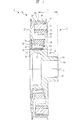
【発明を実施するための最良の形態】
図1に示すように、本発明のアイソレーション・ダンパプーリは、ダンパ部1とアイソレーションプーリ部2とを備えており、ダンパ部1はダンパ手段を構成し、アイソレーションプーリ部2はプーリ手段を構成している。ダンパ部1は、ハブ10、環状質量体11および環状弾性体12を備え、クランクシャフトの捩り振動を低減する機能を有する。
【0032】
ハブ10は、クランクシャフト(不図示)が組み込まれる貫通孔13を有するボス部14と、このボス部14から放射方向に延出する円盤部15と、この円盤部15の周縁部から軸方向に延出し、ボス部14の中心軸Oに同軸状の外側円筒部16とを有し、円盤部15には中心軸Oと同軸状の外周面17を有する内側円筒部18が円盤部15から外側円筒部16に平行に軸方向に延出して第1の嵌合部として設けられており、外側円筒部16と内側円筒部18との間には環状のスペースが形成される。図示する実施の形態にあっては、ハブ10は鋳造によりこれを構成する上記各部が一体に成形されている。
【0033】
環状質量体11は、ハブ10の外側円筒部16の外側に同軸状に配置されている。環状弾性体12は加硫ゴム等の弾性材料により成形され、環状質量体11の内周面とハブ10の外側円筒部16の外周面との間に圧入されている。
【0034】
一方、アイソレーションプーリ部2は、プーリ部21とアイソレーションリング(支持手段)22とこれらの間に固定される環状弾性体23とを備えており、主にエンジンのアイドル回転時等のようにエンジン低回転時のエンジンのトルク変動によって発生するクランクシャフトの速度変動を遮断する機能を有する。
【0035】
プーリ部21は、環状質量体11の外周面を覆う円筒部24と、環状質量体11の端面を覆うカバー部25とを有し、全体的に円筒形状となっており、円筒部24が環状質量体11と同軸状となってダンパ部1に組み付けられる。円筒部24の外周面には、補機駆動用の無端ベルト(不図示)が掛け渡される環状のプーリ溝26が軸方向に所定の間隔で複数本形成されている。
【0036】
アイソレーションリング22は、中心軸Oと同軸状となって内側円筒部(第1の嵌合部)18の外側に配置される円筒状の嵌合部(第2の嵌合部)27と、この嵌合部27の端部から放射方向に延出する支持部28とを有しており、全体的にリング状となっている。アイソレーションリング22は、本実施の形態にあっては、板金を用いてプレス加工により成形される。
【0037】
環状弾性体23は、加硫ゴム等の弾性材料により構成され、軸方向の一端がプーリ部21のカバー部25の径方向内方部の内面に固定され、他端がアイソレーションリング22の支持部28の内面に固定されており、環状弾性体23はプーリ部21とアイソレーションリング22の間で捩り変形することによってクランクシャフトの速度変動を吸収する。
【0038】
アイソレーションプーリ部2がダンパ部1に装着された状態のもとで、環状弾性体23に圧縮力を加えるために、内側円筒部18の外側にはプレッシャーリング31が押圧手段として配置される。このプレッシャーリング31は中心軸Oと同軸状となって嵌合部27に嵌合される円筒形状の嵌合部(第3の嵌合部)32と、この嵌合部32の端部から放射方向に延出する押圧部33とを備えており、全体的にリング状となっている。このプレッシャーリング31は板金を用いてプレス加工により成形される。
【0039】
嵌合部32はアイソレーションリング22の嵌合部27に圧入されて同軸状に嵌合し、嵌合部32の外周面は嵌合部27の内周面に面接合している。嵌合部32はハブ10の内側円筒部18に圧入されて同軸状に嵌合し、嵌合部32の内周面は内側円筒部18の外周面17に面接合している。これらの内側円筒部18,嵌合部27,嵌合部32が相互に嵌合することによって、ダンパ部1とアイソレーションプーリ部2とが組み立てられ、環状弾性体23は軸方向に予圧縮された状態となる。押圧部33とカバー部25との間にはスラストベアリング34が配置され、押圧部33はスラストベアリング34を介してプーリ部21のカバー部25を押圧し、これにより、環状弾性体23に予圧縮が付与される。環状質量体11の外周面と円筒部24の内周面との間には、ジャーナルベアリング35が設けられている。これらのベアリング34,35は樹脂により成形されている。
【0040】
上述したアイソレーションリング22の嵌合部27とプレッシャーリング31の嵌合部32との嵌合位置は軸方向に調整可能となっているので、アイソレーション・ダンパプーリの組立の際に、支持部28と押圧部33との離間長を軸方向に調整することができる。これにより、プレッシャーリング31をアイソレーションリング22へ組み付ける際に、環状弾性体23に軸方向に所定の予圧縮を付与することができる。プレッシャーリング31の嵌合部32とハブ10の内側円筒部18との軸方向の位置も調整可能となっているので、アイソレーション・ダンパプーリの組立の際に、ダンパ部1とアイソレーションプーリ部2との軸方向の相対位置を調整することができる。これにより、ダンパ部1の取付部端面14aと軸方向中央のプーリ溝26aとの軸方向の離間長Lを調整することができる。したがって、環状弾性体23に加えられる予圧縮を許容範囲内に保持しつつ、アイソレーションプーリ部2のダンパ部1に対する軸方向位置、つまり離間長Lを所定の公差の範囲内に収めることができるので、プーリ部21,アイソレーションリング22およびプレッシャーリング31を高い精度で加工することが不要となる。
【0041】
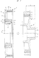
次に、図2および図3に基づいて本実施の形態であるアイソレーション・ダンパプーリの製造方法の一例について説明する。
【0042】
まず、アイソレーションプーリ部2の組立工程を図2に基づいて説明すると、プーリ部21のカバー部25の内面とアイソレーションリング22の支持部28の内面との間には、環状弾性体23が予め加硫接着されており、図2に示すようにプーリ部21は予め準備工程において製造されている。プーリ部21のカバー部25とプレッシャーリング31の押圧部33との間にスラストベアリング34を介在させた状態の下で、プレッシャーリング31の嵌合部32をアイソレーションリング22の嵌合部27を軸方向に圧入して両方の嵌合部27,32を嵌合させることにより、プレッシャーリング31がアイソレーションプーリ部2に組み付けられる。次いで、プーリ部21の開口側端部から円筒部24の内周面にジャーナルベアリング35が装着され、アイソレーションプーリ部2の組立が完了する。
【0043】
両方の嵌合部27,32を嵌合させる際に、アイソレーションリング22とプレッシャーリング31との離間長(支持部28と押圧部33との離間長)が所定の寸法となるように、位置決め治具を用いてアイソレーションプーリ部2の軸方向長さを調整するようにしても良い。
【0044】
ダンパ部1は、図3に示すように、ハブ10の外側円筒部16の外側に環状弾性体12を介して環状質量体11を組み付けることにより、予め準備工程において製造されている。
【0045】
次に、ダンパ部1とアイソレーションプーリ部2の組み付け工程を図3に基づいて説明する。所定箇所に一時的に固定されたダンパ部1に対し、油圧アクチュエータ(不図示)を用いてアイソレーションプーリ部2をスライドさせ、油圧アクチュエータの押圧力によってプレッシャーリング31の嵌合部32をハブ10の内側円筒部18に軸方向に圧入する。これにより、内側円筒部18と嵌合部32は嵌合し、ダンパ部1とアイソレーションプーリ部2とが組み付けられる。
【0046】
ダンパ部1とアイソレーションプーリ部2との組み付けの際には、端面14aから軸方向に長さLだけ離間した位置にレーザー光を照射し、アイソレーションプーリ部2がダンパ部1に軸方向に押されて、レーザー光の照射位置が中央のプーリ溝26aの底部とが一致した時に、油圧アクチュエータの押圧力を解除すると、ダンパ部1の取付部の端面14aとプーリ溝との軸方向の離間長が所定の公差の範囲内に確実に収められる。
【0047】
以上のように、本実施の形態に係るアイソレーション・ダンパプーリによれば、アイソレーションリング22の嵌合部27にプレッシャーリング31の嵌合部32を軸方向に圧入して両者を嵌合させ、その後、プレッシャーリング31の嵌合部32をハブ10の内側円筒部18に軸方向に圧入して両者を嵌合させれば、ダンパ部1に対してアイソレーションプーリ部2のプーリ溝26の組み付け位置が軸方向に調整可能であり、このため、アイソレーションリングの厚さやプレッシャーリング31の加工に高い精度を要求することなく、ダンパ部1の端面14aとプーリ溝26の底部との軸方向の離間長L1を所定の公差の範囲内に収めることができる。また、組み付けの際の溶接が不要となり、溶接に起因する組立作業の繁雑さが解消されるとともに各部材の材料選択の自由度が高められる。
【0048】
アイソレーションリングの嵌合部にプレッシャーリングの嵌合部を軸方向に圧入して両者を嵌合するので、組み付けの際に、アイソレーションリングとプレッシャーリングとの離間長を軸方向に調整することができ、アイソレーションリングやプレッシャーリング31のプレス加工に高い精度が要求されず、環状弾性体23に軸方向に所定の予圧縮を付与することができる。
【0049】
ダンパ部1の内側円筒部18は中心軸Oに同軸状に設けられており、この内側円筒部18にアイソレーションプーリ部2のプレッシャーリング31の嵌合部32が嵌合するため、ダンパ部1とアイソレーションプーリ部2との径方向の位置合わせが不要となり、両者の組み付けを容易に行うことができる。
【0050】
上述した実施の形態にあっては、プレッシャーリング31の嵌合部32の先端がハブ10の方向を指向し、アイソレーションリング22の嵌合部27の先端がプレッシャーリング31の方向を指向しているが、嵌合部32の先端と嵌合部27の先端が双方ともハブ10の方向を指向するようにしても良い。
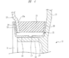
【0051】
図4は本発明の他の実施の形態であるアイソレーション・ダンパプーリの一部を示す断面図である。上述した実施の形態にあっては、プレッシャーリング31の嵌合部32とアイソレーションリング22の嵌合部27とが相互に嵌合しているのに対し、図4に示す場合には、両方の嵌合部27,32が内側円筒部18に軸方向に別々の位置で嵌合している。図4に示すアイソレーション・ダンパプーリを製造するには、まず、アイソレーションリング22の嵌合部27を内側円筒部18に軸方向に支持部28の外面がハブ10の円盤部15に当接するまで圧入して嵌合部27を直接内側円筒部18に嵌合させる。次いで、プレッシャーリング31の嵌合部32を内側円筒部18に軸方向に圧入し、プレッシャーリング31とアイソレーションリング22とで環状弾性体23に所定の予圧縮を付与するとともに、ダンパ部1の端面14aとプーリ溝26との軸方向の長さが所定長となる位置に嵌合部32を内側円筒部18に直接嵌合させる。このように、アイソレーションプーリ部2をダンパ部1に組み付けた後に、プレッシャーリング31をダンパ部1に組み付けてこれを組み付ける際に環状弾性体23に予圧縮を加えながらプーリ溝26のダンパ部1に対する軸方向位置を設定するようにしても良い。
【0052】
プレッシャーリング31の嵌合部32をアイソレーションリング22の嵌合部27の外側に嵌合する場合には、アイソレーションリング22の嵌合部27を内側円筒部18に嵌合させた後に、プレッシャーリング31の嵌合部32をアイソレーションリング22の嵌合部27の外側に嵌合させて環状弾性体23に予圧縮を加えながらプーリ溝26のダンパ部1に対する軸方向位置を設定するようにしても良い。
【0053】
【産業上の利用可能性】
本発明のアイソレーション・ダンパプーリは、エンジンのクランクシャフトの回転トルクを無端ベルトを介して種々の補機に伝達するために適用することができる。
【図面の簡単な説明】
【図1】本発明の一実施の形態であるアイソレーション・ダンパプーリを示す断面図である。
【図2】図1に示したアイソレーションプーリ部の組立工程を示す断面図である。
【図3】図1に示したダンパ部とアイソレーションプーリ部の組立工程を示す断面図である。
【図4】他の実施の形態であるアイソレーション・ダンパプーリの一部を示す断面図である。
【図5】従来のアイソレーション・ダンパプーリの一部を示す断面図である。
【符号の説明】
1 ダンパ部
10 ハブ
11 環状質量体
12 環状弾性体
15 円盤部
16 外側円筒部
18 内側円筒部
21 プーリ部
23 環状弾性体
24 円筒部
25 カバー部
26 プーリ溝
27 嵌合部
28 支持部
31 プレッシャーリング
32 嵌合部
33 押圧部[0001]
【Technical field】
The present invention relates to a technology of an isolation damper pulley that is attached to a crankshaft of an engine and transmits the torque of the crankshaft to various auxiliary machines via an endless belt, and mainly relates to an engine at a low engine speed such as at idling rotation. The present invention relates to a technology of an isolation damper pulley that cuts off the crankshaft speed fluctuation caused by the torque fluctuation and reduces the torsional vibration of the crankshaft.
[0002]
[Background]
For example, as described in Japanese Patent Application Laid-Open No. 2001-159448, the isolation damper pulley includes a damper portion attached to the crankshaft and an isolation pulley portion assembled to the damper portion. The damper portion has a hub mounted on the crankshaft and an annular mass body attached to the cylindrical portion of the hub via an annular elastic body. The isolation pulley portion includes a cylindrical portion having a pulley groove formed on the outer peripheral surface, a pulley portion including a cover portion extending in the center direction from one end portion of the cylindrical portion, and an annular elastic body having one end portion fixed to the cover portion. The other end of the annular elastic body is fixed to the hub via a support member.
[0003]
DISCLOSURE OF THE INVENTION
[0004]
[Problems to be solved by the invention]
FIG. 5 is a cross-sectional view showing a part of a conventional isolation damper pulley, and this isolation damper pulley has a
[0005]
On the other hand, the
[0006]
The pulley portion 51 includes a
[0007]
A pressing
[0008]
A journal bearing 66 is mounted between the outer peripheral surface of the
[0009]
An example of the assembly procedure of the
[0010]
The isolation damper pulley is attached to the tip of the crankshaft (not shown) from the
[0011]
However, in the conventional isolation damper pulley described above, the
[0012]
For this reason, in order to keep the separation length L1 within a predetermined tolerance range, it is necessary to process the thickness of the
[0013]
On the other hand, after the assembly of the
[0014]
Furthermore, since the damper portion, the isolation pulley portion, and the pressing member are assembled by welding, there is room for improvement in terms of the complexity of work caused by welding and the degree of freedom in selecting the material that constitutes each member.
[0015]
The objective of this invention is providing the isolation damper pulley which can adjust the assembly position of the pulley groove of an isolation pulley part with respect to a damper part to an axial direction.
[0016]
Another object of the present invention is to keep the axial length of the damper portion and the pulley groove within a predetermined tolerance range without increasing the accuracy of the thickness of the support member and the length of the cylindrical portion of the pressing member. An object of the present invention is to provide an isolation damper pulley that can be used.
[0017]
Another object of the present invention is an isolation that can impart predetermined precompression to the elastic body in the axial direction without increasing the accuracy of the bending position of the support portion of the support member and the length of the cylindrical portion of the pressing member.・ To provide a damper pulley.
[0018]
Another object of the present invention is to eliminate the complexity of assembling work caused by welding without joining the damper part, the isolation pulley part, and the pressing member by welding, and to increase the freedom of material selection for each member. An object of the present invention is to provide an isolation damper pulley that can be enhanced.
[0020]
[Means for Solving the Problems]
The isolation damper pulley of the present invention is an isolation damper pulley that is mounted on a crankshaft of an engine, and a hub having a mounting hole for the crankshaft, A first fitting portion provided coaxially with the central axis of the mounting hole in the hub; A damper means comprising an annular mass body mounted on an outer cylindrical portion provided on the hub via a first elastic body, and a cylinder disposed on the outer side of the annular mass body with a pulley groove formed on the outer periphery. And a pulley portion including a cover portion extending in the center direction from one axial end portion of the cylindrical portion, one end is fixed to the damper means side, and the other end is fixed to the pulley portion side. A second elastic body pre-compressed to A third fitting portion that is axially press-fitted into the first fitting portion and coaxial with the first fitting portion; Pressing means for pressing the pulley part in the axial direction and applying axial pre-compression to the second elastic body; The fixing position of the pressing means with respect to the first fitting portion can be adjusted in the axial direction. It is characterized by that.
[0021]
The isolation damper pulley of the present invention , Second fitting portion coaxial with the central axis Is provided, Support means for supporting the other axial end of the second elastic body Have The second fitting portion and the third fitting portion are press-fitted to each other in the axial direction and fitted coaxially, and among the second fitting portion and the third fitting portion An inner fitting portion is axially press-fitted into the first fitting portion and is fitted coaxially.
[0022]
The isolation damper pulley of the present invention is characterized in that the first fitting portion, the second fitting portion, and the third fitting portion are cylindrical.
[0023]
In the isolation damper pulley of the present invention, the outer peripheral surface of the third fitting portion is fitted to the inner peripheral surface of the second fitting portion, and the inner peripheral surface of the third fitting portion is the first It fits on the outer peripheral surface of 1 fitting part.
[0024]
The isolation damper pulley of the present invention A second fitting portion coaxial with the central axis is provided, and has a supporting means for supporting the other end portion in the axial direction of the second elastic body, The second fitting portion and the third fitting portion are fitted into the first fitting portion by being press-fitted in the first fitting portion in an axial direction without being fitted to each other. It is characterized by that.
[0025]
An isolation damper pulley manufacturing method of the present invention is an isolation damper pulley manufacturing method for mounting on an engine crankshaft, the hub having a mounting hole for the crankshaft, and the hub including the mounting hole. A step of preparing a damper means comprising a first fitting portion provided coaxially with a central axis and an annular mass body mounted on the outer cylindrical portion provided on the hub via a first elastic body. And a pulley groove is formed in the outer peripheral portion and is arranged outside the annular mass body. Cylinder Department and the concerned Cylinder A cover portion extending in the center direction from one axial end portion of the portion and supporting one axial end portion of the second elastic body, and a second fitting portion coaxial with the first fitting portion. And supporting means for supporting the other axial end of the second elastic body. Rupu A second fitting portion of the pressing means having a step of preparing a roller means, a pressing portion facing the cover portion, and a third fitting portion coaxial with the central axis. The second fitting portion and the third fitting in a state in which a predetermined precompression is applied to the second elastic body in the axial direction by the support means and the pressing means. A step of coaxially fitting a portion, and an inner fitting portion of the second fitting portion and the third fitting portion are axially press-fitted into the first fitting portion, And a step of fitting the inner fitting portion coaxially with the first fitting portion at a position where the axial separation distance between the end surface of the damper means and the pulley groove is a predetermined length. It is characterized by.
[0026]
An isolation damper pulley manufacturing method of the present invention is an isolation damper pulley manufacturing method for mounting on an engine crankshaft, the hub having a mounting hole for the crankshaft, and the hub including the mounting hole. A step of preparing a damper means comprising a first fitting portion provided coaxially with a central axis and an annular mass body mounted on the outer cylindrical portion provided on the hub via a first elastic body. And a pulley groove is formed in the outer peripheral portion and is arranged outside the annular mass body. Cylinder Department and the concerned Cylinder A cover portion extending in the center direction from one axial end portion of the portion and supporting one axial end portion of the second elastic body, and a second fitting portion coaxial with the first fitting portion. And supporting means for supporting the other axial end of the second elastic body. Rupu A step of preparing a rolling means, and press-fitting the second fitting portion into the first fitting portion in the axial direction, and coaxially inserting the second fitting portion into the first fitting portion. A step of fitting, a pressing portion having a pressing portion facing the cover portion, and a third fitting portion coaxial with the central axis, and press-fitted into the first fitting portion in the axial direction; And the pressing means apply a predetermined pre-compression to the second elastic body in the axial direction, and the axial separation distance between the end surface of the damper means and the pulley groove is a predetermined length. And a step of coaxially fitting a third fitting portion to the first fitting portion.
[0027]
【The invention's effect】
In the above-described present invention, the second fitting portion and the third fitting portion are press-fitted in the axial direction and fitted coaxially, and the second fitting portion and the third fitting portion are fitted together. Since the damper portion and the isolation pulley are assembled by press-fitting the inner fitting portion of the fitting portion into the first fitting portion in the axial direction, the isolation pulley portion with respect to the damper portion is assembled. The assembly position can be adjusted. As a result, the axial dimension between the end face of the damper portion and the pulley groove can be kept within a predetermined tolerance range without increasing the thickness of the support member and the pressing accuracy of the pressing member.
[0028]
Since the second fitting portion of the support member and the third fitting portion of the pressing member are press-fitted in the axial direction and are fitted together coaxially, the supporting member and the pressing member are pressed when they are assembled. The axial separation distance from the member can be adjusted. Thereby, predetermined | prescribed compression of an axial direction can be provided to an elastic body, without raising the press work precision of a supporting member or a press member.
[0029]
The second fitting portion and the third fitting portion are press-fitted in the axial direction and fitted coaxially, and the inner fitting of the second fitting portion and the third fitting portion is performed. Since the damper part and the isolation pulley part are assembled by press-fitting the part into the first fitting part in the axial direction, the damper part and the isolation pulley part are aligned in the radial direction. It can be assembled without any problems.
[0030]
Since the damper, isolation pulley, and pressing member are assembled by fitting, they are assembled without welding, eliminating the complexity of assembly work caused by welding, and freedom of material selection for each member The degree is increased.
[0031]
BEST MODE FOR CARRYING OUT THE INVENTION
As shown in FIG. 1, the isolation damper pulley of the present invention includes a damper portion 1 and an
[0032]
The
[0033]
The annular
[0034]
On the other hand, the
[0035]
The
[0036]
The
[0037]
The annular
[0038]
In order to apply a compressive force to the annular
[0039]
The
[0040]
Since the fitting position of the
[0041]
Next, an example of a method for manufacturing the isolation damper pulley according to the present embodiment will be described with reference to FIGS.
[0042]
First, the assembly process of the
[0043]
Positioning is performed so that the separation length between the
[0044]
As shown in FIG. 3, the damper portion 1 is manufactured in advance in a preparation step by assembling the annular
[0045]
Next, the assembly process of the damper part 1 and the
[0046]
When the damper part 1 and the
[0047]
As described above, according to the isolation damper pulley according to the present embodiment, the
[0048]
Since the fitting part of the pressure ring is press-fitted in the axial direction into the fitting part of the isolation ring to fit them together, the separation length between the isolation ring and the pressure ring must be adjusted in the axial direction during assembly. Therefore, high precision is not required for the pressing of the isolation ring or the
[0049]
The inner
[0050]
In the embodiment described above, the distal end of the
[0051]
FIG. 4 is a cross-sectional view showing a part of an isolation damper pulley according to another embodiment of the present invention. In the embodiment described above, the
[0052]
When fitting the
[0053]
[Industrial applicability]
The isolation damper pulley of the present invention can be applied to transmit the rotational torque of the crankshaft of an engine to various auxiliary machines via an endless belt.
[Brief description of the drawings]
FIG. 1 is a cross-sectional view showing an isolation damper pulley according to an embodiment of the present invention.
FIG. 2 is a cross-sectional view showing an assembly process of the isolation pulley portion shown in FIG. 1;
3 is a cross-sectional view showing an assembly process of the damper portion and the isolation pulley portion shown in FIG. 1. FIG.
FIG. 4 is a cross-sectional view showing a part of an isolation damper pulley according to another embodiment.
FIG. 5 is a cross-sectional view showing a part of a conventional isolation damper pulley.
[Explanation of symbols]
1 Damper section
10 Hub
11 Annular mass
12 Annular elastic body
15 Disc part
16 Outer cylindrical part
18 Inner cylinder
21 Pulley
23 Annular elastic body
24 Cylindrical part
25 Cover part
26 Pulley groove
27 Fitting part
28 Supporting part
31 Pressure ring
32 Fitting part
33 Pressing part
Claims (7)
前記クランクシャフトへの取付孔を有するハブと、当該ハブに前記取付孔の中心軸と同軸状に設けられた第1の嵌合部と、前記ハブに設けられた外側円筒部に第1の弾性体を介して装着される環状質量体とを備えるダンパ手段と、
外周部にプーリ溝が形成され前記環状質量体の外側に配置される円筒部と、当該円筒部の軸方向一端部から中心方向に延出するカバー部とを備えるプーリ部と、
一端が前記ダンパ手段側に固定され、他端が前記プーリ部側に固定され、軸方向に予圧縮された第2の弾性体と、
前記第1の嵌合部に軸方向に圧入されて前記第1の嵌合部と同軸状の第3の嵌合部を有し、前記プーリ部を軸方向に押圧し、前記第2の弾性体に軸方向の予圧縮を付与する押圧手段とを備え、
当該押圧手段の前記第1の嵌合部に対する固定位置が軸方向に調整可能であることを特徴とするアイソレーション・ダンパプーリ。An isolation damper pulley mounted on the engine crankshaft,
A hub having a mounting hole for the crankshaft, a first fitting portion provided coaxially with the central axis of the mounting hole in the hub, and an outer cylindrical portion provided in the hub have a first elasticity. A damper means comprising an annular mass mounted through the body;
A pulley part including a cylindrical part formed on the outer periphery of the annular mass body and disposed outside the annular mass body, and a cover part extending in the center direction from one axial end of the cylindrical part;
A second elastic body having one end fixed to the damper means side and the other end fixed to the pulley portion side and pre-compressed in the axial direction;
The second fitting portion has a third fitting portion that is press-fitted in the first fitting portion in the axial direction and is coaxial with the first fitting portion , presses the pulley portion in the axial direction, and the second elasticity Pressing means for applying axial pre-compression to the body,
An isolation damper pulley characterized in that the fixing position of the pressing means with respect to the first fitting portion can be adjusted in the axial direction .
前記クランクシャフトへの取付孔を有するハブと、当該ハブに前記取付孔の中心軸と同軸状に設けられた第1の嵌合部と、前記ハブに設けられた外側円筒部に第1の弾性体を介して装着される環状質量体とを備えるダンパ手段を準備する工程と、
外周部にプーリ溝が形成され前記環状質量体の外側に配置される円筒部と、当該円筒部の軸方向一端部から中心方向に延出し第2の弾性体の軸方向の一端部を支持するカバー部と、前記第1の嵌合部と同軸状の第2の嵌合部が設けられ前記第2の弾性体の軸方向の他端部を支持する支持手段とを有するプーリ手段を準備する工程と、
前記カバー部に対向する押圧部と前記中心軸と同軸状の第3の嵌合部を有する押圧手段の当該第3の嵌合部を前記第2の嵌合部に軸方向に圧入し、前記支持手段と前記押圧手段とで前記第2の弾性体に軸方向に所定の予圧縮を付与した状態で前記第2の嵌合部と前記第3の嵌合部とを同軸状に嵌合する工程と、
前記第2の嵌合部と前記第3の嵌合部のうち内側の嵌合部を前記第1の嵌合部に軸方向に圧入し、前記ダンパ手段の端面と前記プーリ溝との軸方向の離間長が所定長となった位置に、前記内側の嵌合部を前記第1の嵌合部に同軸状に嵌合する工程とを有することを特徴とするアイソレーション・ダンパプーリの製造方法。A method for manufacturing an isolation damper pulley to be mounted on an engine crankshaft,
A hub having a mounting hole for the crankshaft, a first fitting portion provided coaxially with the central axis of the mounting hole in the hub, and an outer cylindrical portion provided in the hub have a first elasticity. Providing damper means comprising an annular mass mounted through the body;
A pulley groove is formed on the outer peripheral portion and is arranged outside the annular mass body, and extends from the axial end of the cylindrical portion toward the center to support the axial end of the second elastic body. A pulley means having a cover part and a support means provided with a second fitting part coaxial with the first fitting part and supporting the other end part in the axial direction of the second elastic body is prepared. Process,
The third fitting portion of the pressing means having a pressing portion facing the cover portion and a third fitting portion coaxial with the central axis is press-fitted in the axial direction into the second fitting portion, and The second fitting portion and the third fitting portion are coaxially fitted in a state where a predetermined precompression is applied to the second elastic body in the axial direction by the support means and the pressing means. Process,
The inner fitting portion of the second fitting portion and the third fitting portion is press-fitted in the first fitting portion in the axial direction, and the axial direction between the end surface of the damper means and the pulley groove And a step of coaxially fitting the inner fitting portion to the first fitting portion at a position where the separation length of the first and second engagement portions becomes a predetermined length.
前記クランクシャフトへの取付孔を有するハブと、当該ハブに前記取付孔の中心軸と同軸状に設けられた第1の嵌合部と、前記ハブに設けられた外側円筒部に第1の弾性体を介して装着される環状質量体とを備えるダンパ手段を準備する工程と、
外周部にプーリ溝が形成され前記環状質量体の外側に配置される円筒部と、当該円筒部の軸方向一端部から中心方向に延出し第2の弾性体の軸方向の一端部を支持するカバー部と、前記第1の嵌合部と同軸状の第2の嵌合部が設けられ前記第2の弾性体の軸方向の他端部を支持する支持手段とを有するプーリ手段を準備する工程と、
前記第2の嵌合部を前記第1の嵌合部に軸方向に圧入し、前記第2の嵌合部を前記第1の嵌合部に同軸状に嵌合する工程と、
前記カバー部に対向する押圧部と前記中心軸と同軸状の第3の嵌合部を有する押圧手段を前記第1の嵌合部に軸方向に圧入し、前記支持手段と前記押圧手段とで前記第2の弾性体に軸方向に所定の予圧縮を付与するとともに、前記ダンパ手段の端面と前記プーリ溝との軸方向の離間長が所定長となった位置に前記第3の嵌合部を前記第1の嵌合部に同軸状に嵌合する工程とを有することを特徴とするアイソレーション・ダンパプーリの製造方法。A method for manufacturing an isolation damper pulley to be mounted on an engine crankshaft,
A hub having a mounting hole for the crankshaft, a first fitting portion provided coaxially with the central axis of the mounting hole in the hub, and an outer cylindrical portion provided in the hub have a first elasticity. Providing damper means comprising an annular mass mounted through the body;
A pulley groove is formed on the outer peripheral portion and is arranged outside the annular mass body, and extends from the axial end of the cylindrical portion toward the center to support the axial end of the second elastic body. A pulley means having a cover part and a support means provided with a second fitting part coaxial with the first fitting part and supporting the other end part in the axial direction of the second elastic body is prepared. Process,
Press-fitting the second fitting portion into the first fitting portion in the axial direction, and fitting the second fitting portion coaxially with the first fitting portion;
A pressing means having a pressing part facing the cover part and a third fitting part coaxial with the central axis is press-fitted in the first fitting part in the axial direction, and the supporting means and the pressing means A predetermined pre-compression is applied to the second elastic body in the axial direction, and the third fitting portion is located at a position where the axial separation length between the end surface of the damper means and the pulley groove is a predetermined length. And a step of fitting the first fitting portion coaxially with the first fitting portion.
Applications Claiming Priority (3)
| Application Number | Priority Date | Filing Date | Title |
|---|---|---|---|
| JP2003293972 | 2003-07-11 | ||
| JP2003293972 | 2003-07-11 | ||
| PCT/JP2004/010156 WO2005005865A1 (en) | 2003-07-11 | 2004-07-09 | Isolation damper pulley and method of producing the same |
Publications (2)
| Publication Number | Publication Date |
|---|---|
| JPWO2005005865A1 JPWO2005005865A1 (en) | 2006-08-24 |
| JP4391990B2 true JP4391990B2 (en) | 2009-12-24 |
Family
ID=34056208
Family Applications (1)
| Application Number | Title | Priority Date | Filing Date |
|---|---|---|---|
| JP2005511591A Expired - Fee Related JP4391990B2 (en) | 2003-07-11 | 2004-07-09 | Isolation damper pulley and manufacturing method thereof |
Country Status (10)
| Country | Link |
|---|---|
| US (1) | US8038554B2 (en) |
| EP (1) | EP1645783B1 (en) |
| JP (1) | JP4391990B2 (en) |
| KR (1) | KR100838427B1 (en) |
| CN (1) | CN100455850C (en) |
| AT (1) | ATE386896T1 (en) |
| DE (1) | DE602004011941T2 (en) |
| ES (1) | ES2297446T3 (en) |
| PL (1) | PL1645783T3 (en) |
| WO (1) | WO2005005865A1 (en) |
Families Citing this family (45)
| Publication number | Priority date | Publication date | Assignee | Title |
|---|---|---|---|---|
| JP4572739B2 (en) * | 2005-05-20 | 2010-11-04 | 株式会社ジェイテクト | Rotation fluctuation absorbing damper pulley |
| JP4766372B2 (en) * | 2005-06-23 | 2011-09-07 | 株式会社フコク | Pulley with damper and manufacturing method thereof |
| JP4716012B2 (en) * | 2005-10-14 | 2011-07-06 | Nok株式会社 | Torque fluctuation absorbing damper |
| DE102006016202B3 (en) * | 2006-04-06 | 2007-07-05 | Carl Freudenberg Kg | Belt pulley, has integrated torsional vibration damper, hub ring and flywheel rim surrounding hub ring with first radial distance, whereas first spring body is arranged in first formed crack over first space |
| JP2007278417A (en) * | 2006-04-07 | 2007-10-25 | Fukoku Co Ltd | Damper and isolation damper pulley |
| KR100780993B1 (en) | 2006-11-07 | 2007-11-30 | 지엠대우오토앤테크놀로지주식회사 | A damper pulley device |
| WO2008058499A2 (en) * | 2006-11-15 | 2008-05-22 | Luk Lamellen Und Kupplungsbau Beteiligungs Kg | Drive wheel with at least one drive disc and a rotational vibration damping device |
| JP4435810B2 (en) * | 2007-06-26 | 2010-03-24 | 三ツ星ベルト株式会社 | Pulley structure and accessory drive system using the same |
| US7682255B2 (en) * | 2007-06-29 | 2010-03-23 | Harley-Davidson Motor Company Group, LLC | Compensator assembly for a motorcycle primary drive |
| DE102007033336A1 (en) * | 2007-07-16 | 2009-01-29 | Voith Turbo Hochelastische Kupplungen Gmbh & Co. Kg | Torsionally flexible coupling |
| EP2103828B1 (en) * | 2008-03-20 | 2012-10-17 | IPROTEC Maschinen- und Edelstahlprodukte GmbH | Coupling |
| JP5757456B2 (en) * | 2011-03-24 | 2015-07-29 | Nok株式会社 | Drive system dynamic damper |
| US9382994B2 (en) * | 2012-05-08 | 2016-07-05 | Halla Climate Control Corp. | Pulley assembly of compressor and method of manufacturing the same |
| CN102720799A (en) * | 2012-06-18 | 2012-10-10 | 湖北广奥减振器制造有限公司 | Two-stage rubber vibration absorber |
| US10060502B2 (en) | 2012-10-12 | 2018-08-28 | Litens Automotive Partnership | Isolator for use with engine that is assisted or started by an MGU or a motor through an endless drive member |
| DE102013202690B4 (en) | 2013-02-20 | 2022-01-05 | Bayerische Motoren Werke Aktiengesellschaft | Torsional vibration damper |
| US9273773B2 (en) * | 2013-03-15 | 2016-03-01 | Magna Powertrain, Inc. | One-piece inertia ring and method of manufacturing the one-piece inertia ring |
| CN105393024B (en) | 2013-05-23 | 2018-04-03 | 利滕斯汽车合伙公司 | Reduce the isolator with double-acting spring system of noise |
| JP6182978B2 (en) * | 2013-05-24 | 2017-08-23 | 株式会社ジェイテクト | Damper pulley manufacturing method and damper pulley manufacturing apparatus |
| US10267405B2 (en) | 2013-07-24 | 2019-04-23 | Litens Automotive Partnership | Isolator with improved damping structure |
| CN105452711B (en) | 2013-07-25 | 2017-12-08 | 利滕斯汽车合伙公司 | Spring assembly for isolator |
| JP6280345B2 (en) * | 2013-11-01 | 2018-02-14 | Nok株式会社 | Rotation fluctuation absorbing damper |
| CN105765253B (en) | 2013-11-10 | 2019-06-14 | 利滕斯汽车合伙公司 | Vibration isolator with dual spring |
| CN106068400B (en) * | 2014-03-05 | 2018-10-09 | 戴科知识产权控股有限责任公司 | Torque-vibration damper |
| KR20170016371A (en) * | 2014-06-09 | 2017-02-13 | 데이코 아이피 홀딩스 엘엘시 | Torsional vibration damper with an interlocked isolator |
| US10030757B2 (en) * | 2014-07-01 | 2018-07-24 | Dayco Ip Holdings, Llc | Torsional vibration damper with an interlocked isolator |
| KR20170051418A (en) * | 2014-09-02 | 2017-05-11 | 데이코 아이피 홀딩스 엘엘시 | Apparatus for a drive system having a cartridge housing one or more elastomer members |
| US10151379B2 (en) * | 2014-10-14 | 2018-12-11 | Dayco Ip Holdings, Llc | Torsional vibration dampers |
| US9982747B2 (en) * | 2015-04-22 | 2018-05-29 | Ford Global Technologies, Llc | Damper hub assembly and method of forming the same |
| KR101724880B1 (en) | 2015-07-24 | 2017-04-10 | 현대자동차주식회사 | Torque transferring apparatus |
| JP2017180529A (en) * | 2016-03-28 | 2017-10-05 | トヨタ自動車株式会社 | Manufacturing method of pulley |
| DE102016216274B4 (en) * | 2016-08-30 | 2018-08-02 | Schaeffler Technologies AG & Co. KG | Pulley decoupler with double hub |
| US20190085934A1 (en) * | 2017-09-21 | 2019-03-21 | Optimized Solutions, LLC | Torsional vibration damper with low elastomer content |
| JP6811702B2 (en) * | 2017-12-19 | 2021-01-13 | Nok株式会社 | Tortional damper |
| FR3078759B1 (en) * | 2018-03-06 | 2020-02-28 | Aktiebolaget Skf | PULLEY DEVICE FOR TENSIONER OR ROLLER |
| KR102441083B1 (en) | 2018-03-08 | 2022-09-06 | 현대자동차주식회사 | Damper pulley for crankshaft |
| DE102018112162B4 (en) * | 2018-05-22 | 2021-03-25 | Schaeffler Technologies AG & Co. KG | Pulley decoupler with molded belt track, slide bearing and axial friction ring |
| CN112673188B (en) * | 2018-09-10 | 2023-09-29 | 利滕斯汽车合伙公司 | Combined isolation and torsional vibration damping device |
| JP7080147B2 (en) * | 2018-09-25 | 2022-06-03 | Nok株式会社 | Rotation fluctuation absorption damper |
| WO2020089566A1 (en) * | 2018-11-02 | 2020-05-07 | Colford Terence | Torsional vibration isolator for attenuating crankshaft vibration |
| DE102020127092A1 (en) * | 2020-09-08 | 2022-03-10 | Schaeffler Technologies AG & Co. KG | Pulley decoupler with a support plate of a vibration absorber connected to a hub component |
| US11796046B2 (en) * | 2021-01-08 | 2023-10-24 | American Axle & Manufacturing, Inc. | Isolated drive assembly with an isolator assembly and a torque limiter for limiting the transmission of torque through an elastomeric element of the isolator assembly |
| KR102578513B1 (en) | 2021-07-15 | 2023-09-20 | 주식회사 피엔디티 | Damper pulley with improved vibration damping |
| CN114396454A (en) * | 2021-12-09 | 2022-04-26 | 东风汽车集团股份有限公司 | Torsional vibration damper and gasoline engine with variable compression ratio |
| CN114700720B (en) * | 2022-04-28 | 2023-04-21 | 中山市敬德智能化科技有限公司 | Roller assembly equipment |
Family Cites Families (15)
| Publication number | Priority date | Publication date | Assignee | Title |
|---|---|---|---|---|
| JPH01116253A (en) | 1987-10-28 | 1989-05-09 | Mitsubishi Motors Corp | Throttle control device |
| JPH01116253U (en) * | 1988-01-29 | 1989-08-04 | ||
| JP3674636B2 (en) * | 1994-02-18 | 2005-07-20 | Nok株式会社 | damper |
| DE4430393C5 (en) * | 1994-08-26 | 2011-06-30 | Carl Freudenberg KG, 69469 | Torsionally flexible coupling with integrated torsional vibration damper |
| FR2730782B1 (en) | 1995-02-17 | 1997-04-25 | Dampers | DRIVE DEVICE COMPRISING A TORSIONAL VIBRATION DAMPER |
| JP2001159448A (en) * | 1999-11-30 | 2001-06-12 | Fukoku Co Ltd | Isolation damper pulley |
| GB2374654A (en) * | 2001-04-04 | 2002-10-23 | Metaldyne Internat | Torsional vibration damper |
| GB2382395A (en) * | 2001-11-21 | 2003-05-28 | Metaldyne Internat | A device for isolating fluctuations in the drive torque of a rotary drive shaft |
| ITTO20020622A1 (en) * | 2002-07-16 | 2004-01-16 | Dayco Europe Srl | INTEGRATED PULLEY-TORSIONAL DAMPER GROUP |
| ITTO20020621A1 (en) * | 2002-07-16 | 2004-01-16 | Dayco Europe Srl | INTEGRATED PULLEY-TORSIONAL DAMPER GROUP |
| JP2004108528A (en) * | 2002-09-20 | 2004-04-08 | Nok Corp | Torque fluctuation absorption damper |
| JP2004162768A (en) * | 2002-11-12 | 2004-06-10 | Nok Corp | Torque fluctuation absorbing damper |
| JP4232620B2 (en) * | 2003-10-31 | 2009-03-04 | 株式会社フコク | Isolation pulley |
| JP4389106B2 (en) * | 2004-04-12 | 2009-12-24 | 株式会社フコク | Isolation pulley |
| JP4572739B2 (en) * | 2005-05-20 | 2010-11-04 | 株式会社ジェイテクト | Rotation fluctuation absorbing damper pulley |
-
2004
- 2004-07-09 JP JP2005511591A patent/JP4391990B2/en not_active Expired - Fee Related
- 2004-07-09 DE DE602004011941T patent/DE602004011941T2/en not_active Expired - Lifetime
- 2004-07-09 KR KR1020067000655A patent/KR100838427B1/en active IP Right Grant
- 2004-07-09 PL PL04747622T patent/PL1645783T3/en unknown
- 2004-07-09 ES ES04747622T patent/ES2297446T3/en not_active Expired - Lifetime
- 2004-07-09 EP EP04747622A patent/EP1645783B1/en not_active Expired - Lifetime
- 2004-07-09 WO PCT/JP2004/010156 patent/WO2005005865A1/en active IP Right Grant
- 2004-07-09 US US10/564,231 patent/US8038554B2/en not_active Expired - Fee Related
- 2004-07-09 AT AT04747622T patent/ATE386896T1/en not_active IP Right Cessation
- 2004-07-09 CN CNB2004800198163A patent/CN100455850C/en not_active Expired - Fee Related
Also Published As
| Publication number | Publication date |
|---|---|
| JPWO2005005865A1 (en) | 2006-08-24 |
| CN100455850C (en) | 2009-01-28 |
| DE602004011941D1 (en) | 2008-04-03 |
| DE602004011941T2 (en) | 2009-02-19 |
| US20060172832A1 (en) | 2006-08-03 |
| ES2297446T3 (en) | 2008-05-01 |
| US8038554B2 (en) | 2011-10-18 |
| PL1645783T3 (en) | 2008-07-31 |
| WO2005005865A1 (en) | 2005-01-20 |
| KR20060039435A (en) | 2006-05-08 |
| CN1823239A (en) | 2006-08-23 |
| EP1645783A4 (en) | 2006-08-02 |
| ATE386896T1 (en) | 2008-03-15 |
| KR100838427B1 (en) | 2008-06-16 |
| EP1645783B1 (en) | 2008-02-20 |
| EP1645783A1 (en) | 2006-04-12 |
Similar Documents
| Publication | Publication Date | Title |
|---|---|---|
| JP4391990B2 (en) | Isolation damper pulley and manufacturing method thereof | |
| JP2005537445A (en) | Integrated pulley and torsional damper assembly | |
| KR100266111B1 (en) | A torsion damping device for motor vehicle | |
| US20080167150A1 (en) | Tensioning roller device | |
| JPH0783282A (en) | Ring-shaped mechanical section and manufacture thereof | |
| JP2574648B2 (en) | Torsional vibration damper | |
| JP4632792B2 (en) | Pulley with damper function | |
| JP4389106B2 (en) | Isolation pulley | |
| EP1382886B1 (en) | An integrated pulley-torsional damper assembly | |
| JP4904781B2 (en) | Pulley with damper and manufacturing method thereof | |
| JP4766372B2 (en) | Pulley with damper and manufacturing method thereof | |
| JP2008057553A (en) | Pulley with damper | |
| JP3732259B2 (en) | 2-mass type flywheel | |
| KR20120104453A (en) | Method of manufacturing isolation damper pulley | |
| JP2022015855A (en) | Torsional damper and method of manufacturing the same | |
| JP3722795B2 (en) | Vehicle drive plate | |
| JP5409169B2 (en) | Pulley with damper | |
| JPH056434Y2 (en) | ||
| JP2024024194A (en) | shaft structure | |
| JPH0854044A (en) | Two mass type flywheel for internal combustion engine | |
| JPH0227694Y2 (en) | ||
| JP4279809B2 (en) | Vehicle drive plate | |
| JP5180015B2 (en) | Pulley with damper | |
| JPH08121537A (en) | Torsional damper | |
| JPS62215144A (en) | Manufacture of damper pulley |
Legal Events
| Date | Code | Title | Description |
|---|---|---|---|
| A521 | Request for written amendment filed |
Free format text: JAPANESE INTERMEDIATE CODE: A523 Effective date: 20090213 |
|
| A131 | Notification of reasons for refusal |
Free format text: JAPANESE INTERMEDIATE CODE: A131 Effective date: 20090623 |
|
| A521 | Request for written amendment filed |
Free format text: JAPANESE INTERMEDIATE CODE: A523 Effective date: 20090824 |
|
| TRDD | Decision of grant or rejection written | ||
| A01 | Written decision to grant a patent or to grant a registration (utility model) |
Free format text: JAPANESE INTERMEDIATE CODE: A01 Effective date: 20090929 |
|
| A01 | Written decision to grant a patent or to grant a registration (utility model) |
Free format text: JAPANESE INTERMEDIATE CODE: A01 |
|
| A61 | First payment of annual fees (during grant procedure) |
Free format text: JAPANESE INTERMEDIATE CODE: A61 Effective date: 20091008 |
|
| FPAY | Renewal fee payment (event date is renewal date of database) |
Free format text: PAYMENT UNTIL: 20121016 Year of fee payment: 3 |
|
| R150 | Certificate of patent or registration of utility model |
Ref document number: 4391990 Country of ref document: JP Free format text: JAPANESE INTERMEDIATE CODE: R150 Free format text: JAPANESE INTERMEDIATE CODE: R150 |
|
| FPAY | Renewal fee payment (event date is renewal date of database) |
Free format text: PAYMENT UNTIL: 20121016 Year of fee payment: 3 |
|
| FPAY | Renewal fee payment (event date is renewal date of database) |
Free format text: PAYMENT UNTIL: 20151016 Year of fee payment: 6 |
|
| R250 | Receipt of annual fees |
Free format text: JAPANESE INTERMEDIATE CODE: R250 |
|
| R250 | Receipt of annual fees |
Free format text: JAPANESE INTERMEDIATE CODE: R250 |
|
| R250 | Receipt of annual fees |
Free format text: JAPANESE INTERMEDIATE CODE: R250 |
|
| R250 | Receipt of annual fees |
Free format text: JAPANESE INTERMEDIATE CODE: R250 |
|
| R250 | Receipt of annual fees |
Free format text: JAPANESE INTERMEDIATE CODE: R250 |
|
| R250 | Receipt of annual fees |
Free format text: JAPANESE INTERMEDIATE CODE: R250 |
|
| R250 | Receipt of annual fees |
Free format text: JAPANESE INTERMEDIATE CODE: R250 |
|
| R250 | Receipt of annual fees |
Free format text: JAPANESE INTERMEDIATE CODE: R250 |
|
| R250 | Receipt of annual fees |
Free format text: JAPANESE INTERMEDIATE CODE: R250 |
|
| LAPS | Cancellation because of no payment of annual fees |