JP2005299839A - Clip seating structure - Google Patents
Clip seating structure Download PDFInfo
- Publication number
- JP2005299839A JP2005299839A JP2004118683A JP2004118683A JP2005299839A JP 2005299839 A JP2005299839 A JP 2005299839A JP 2004118683 A JP2004118683 A JP 2004118683A JP 2004118683 A JP2004118683 A JP 2004118683A JP 2005299839 A JP2005299839 A JP 2005299839A
- Authority
- JP
- Japan
- Prior art keywords
- clip
- vertical wall
- seating
- clip seating
- kicking plate
- Prior art date
- Legal status (The legal status is an assumption and is not a legal conclusion. Google has not performed a legal analysis and makes no representation as to the accuracy of the status listed.)
- Pending
Links
- 238000000465 moulding Methods 0.000 description 5
- 238000004904 shortening Methods 0.000 description 2
- 238000009751 slip forming Methods 0.000 description 2
- 230000008602 contraction Effects 0.000 description 1
- 239000000463 material Substances 0.000 description 1
- NJPPVKZQTLUDBO-UHFFFAOYSA-N novaluron Chemical compound C1=C(Cl)C(OC(F)(F)C(OC(F)(F)F)F)=CC=C1NC(=O)NC(=O)C1=C(F)C=CC=C1F NJPPVKZQTLUDBO-UHFFFAOYSA-N 0.000 description 1
- 238000004080 punching Methods 0.000 description 1
- 229920003002 synthetic resin Polymers 0.000 description 1
- 239000000057 synthetic resin Substances 0.000 description 1
- 238000003466 welding Methods 0.000 description 1
Images


Landscapes
- Connection Of Plates (AREA)
- Insertion Pins And Rivets (AREA)
- Vehicle Interior And Exterior Ornaments, Soundproofing, And Insulation (AREA)
Abstract
Description
本発明は、自動車のキッキングプレート、センターピラートリム、リヤピラートリム或いはドアトリム等の内装部品を車体に装着するためのクリップを着座装着させるためのクリップ着座構造に関する。 The present invention relates to a clip seating structure for seating and mounting a clip for mounting an interior part such as a kicking plate, a center pillar trim, a rear pillar trim or a door trim of an automobile to a vehicle body.
従来、自動車におけるたとえばサイドシルを覆うために、内装部品としてキッキングプレートが用いられており、このキッキングプレート1は、図6および図7に示すように、裏面側が開放した断面コ字状を呈して構成しており、やはり裏面側に一体の縦壁2を設け、縦壁2にキッキングプレート1の裏面に沿うようにクリップ着座部3が連続形成されており、クリップ着座部3には、先端側が開口する開口狭窄部4aとなったクリップ係止孔4が形成されている。
2. Description of the Related Art Conventionally, a kicking plate is used as an interior part to cover, for example, a side sill in an automobile. The
クリップ座3にクリップ5を装着するには、クリップ5の軸部5aを開口狭窄部4aからクリップ係止孔4に挿入し、軸部5aに互いに離間した状態で形成された一対の係合フランジ部5b、5cの間にクリップ着座部3を挟合し、両係合フランジ部5b、5cがクリップ着座部3に係合することによって、クリップ5をクリップ着座部3に装着するようにしており、クリップ係止孔4は、クリップ5の軸部5aよりも大きく構成されて、クリップ5をクリップ着座部3において軸部5aとクリップ係止孔4の大きさの差分移動可能とすることができ、キッキングプレート1をサイドシルに取り付けた後のキッキングプレートの熱収縮を吸収するようにしている。(特許文献1乃至特許文献4参照)。
そして、キッキングプレート1は、通常合成樹脂材を成形型を用いて成形することによって形成した成形品であり、クリップ着座部3がアンダーカットになっているために、上下成形型の他に、図7の一点差線で示すようなスライド駒6を用いて成形することになる。
The
しかしながら、キッキングプレート1の裏面側において、クリップ着座部3を形成するスライド型6のスライド方向(図7の矢印方向)に、例えば、突起7が存在するような場合、成形後にスライド駒6を矢印方向にスライドさせて型抜きするためのスライド量を確保できず、スライド駒6の使用ができないことになる。
However, on the back surface side of the
そこで、図8に示すように、クリップ着座部3における縦壁2から先端部までの全長を短くして、スライド駒6のスライド量を確保することも考えられるが、この場合、クリップ着座部3におけるクリップ5の係合フランジ部5b、5cの係合スペースが少なく、装着後のクリップ5がクリップ係止孔4内を移動することによるキッキングプレート1の熱収縮を吸収できず好ましくない。
Therefore, as shown in FIG. 8, it is conceivable to shorten the total length from the
以上の点に鑑み、スライド駒を使用せずしかもクリップ5の係合フランジ部5b、5cにおけるクリップ着座部3の係合スペースを十分確保するために、図9に示すものが考えられることになる。
In view of the above points, the one shown in FIG. 9 can be considered in order to ensure a sufficient engagement space for the
すなわち、図9に示すものは、縦壁2と一体成形されたクリップ着座部3をキッキングプレート1とは別体のもので構成しており、クリップ着座部3が、キッキングプレート1の裏面側にその成形時に一体に形成しておいた一対の取付けボス8,8に縦壁2の下端に一体形成した台座部9を振動溶着等で溶融して加締め付けることによって、キッキングプレート1に装着するように構成したものである。
That is, the one shown in FIG. 9 includes a
このように構成することによって、キッキングプレート1の裏面側にはアンダーカット形状を持ったクリップ着座部3が存在しないために、スライド駒6の問題は解消され、しかも、別体のクリップ着座部3によって、クリップ5の係合フランジ部5b、5cの係合スペースを十分確保することができことになる。
With this configuration, the
反面、クリップ座3は、取付けボス8,8の上に装着するために、高さ方向に高くなってしまい、キッキングプレート1を車体に取付けようとしても、キッキングプレート1と車体との隙間が小さいために取付けることができず、その結果として、クリップ5による止め点廃止ということになって、車体に対する固定力が弱くなってしまい、しかも、縦壁2および台座部9を有する別体のクリップ着座部3を成形するための別の成形型が必要となって、型費増加の要因となってしまう。
On the other hand, since the
そこで、本発明は、かかる点に鑑み、内装部品において、近接する突起が存在したとしても、スライド駒を用いてクリップ着座部が内装部品と一体に形成でき、しかも、クリップのクリップ座への係合スペースを充分確保可能なクリップ着座構造を提供することを目的としている。 Therefore, in view of such points, the present invention can form the clip seating part integrally with the interior part using the slide piece even if there are adjacent projections in the interior part, and the clip can be engaged with the clip seat. An object of the present invention is to provide a clip seating structure that can secure a sufficient space.
本発明に係るクリップ着座構造は、内装部品の裏面に縦壁部を介してクリップ着座部を形成し、クリップ着座部にクリップを係着保持するクリップ係止孔を形成し、クリップ係止孔にクリップの軸部を挿入して、軸部に形成した一対の係合フランジ部によりクリップ着座部の内外両面を挟合することによってクリップをクリップ着座部に装着するように構成する場合、縦壁部に、一対の係合フランジ部のうちクリップ着座部の内壁側に位置する係合フランジ部を挿入して縦壁部の内壁側より外壁側に延在させる逃がし部を形成したことを特徴とするものである。 In the clip seating structure according to the present invention, the clip seating portion is formed on the back surface of the interior part through the vertical wall portion, the clip latching hole for latching and holding the clip is formed in the clip seating portion, When the clip shaft is inserted and the clip is mounted on the clip seating portion by sandwiching the inner and outer surfaces of the clip seating portion with a pair of engaging flange portions formed on the shaft portion, the vertical wall portion In addition, the engagement flange portion located on the inner wall side of the clip seating portion is inserted into the pair of engagement flange portions to form a relief portion extending from the inner wall side of the vertical wall portion to the outer wall side. Is.
上記のように構成する本発明によれば、たとえ、クリップ着座部の全長を短く設定したとしても、係合フランジ部を逃がし部に挿入して縦壁部の内壁より外壁部側に突出させることによって、クリップ着座部への係合フランジ部の係合スペースが十分確保でき、クリップを軸部とクリップ取付け孔の大きさの差分移動可能にすることができて、内装部品の熱収縮を吸収することができ、しかも、クリップ着座部の全長を短くすることによって、スライド駒のスライド量も十分確保することができる。 According to the present invention configured as described above, even if the overall length of the clip seating portion is set short, the engagement flange portion is inserted into the escape portion and protruded from the inner wall of the vertical wall portion to the outer wall portion side. By this, a sufficient engagement space of the engagement flange portion to the clip seating portion can be secured, the clip can be moved in a differential manner between the size of the shaft portion and the clip mounting hole, and the heat shrinkage of the interior part is absorbed. In addition, the sliding amount of the slide piece can be sufficiently secured by shortening the entire length of the clip seating portion.
以下、図1乃至図8を用いて、本発明を実施するための第1の実施の形態について説明する。 Hereinafter, a first embodiment for carrying out the present invention will be described with reference to FIGS. 1 to 8.
図1は本発明に係る第1の実施の形態を採用した自動車における車室前側部の一部を描画した斜視図、図2は図1におけるキッキングプレートのクリップ着座部付近をクリップを取り付けた状態において拡大して描画した斜視図、図3は図2のA−A断面図である。 FIG. 1 is a perspective view illustrating a part of a front side portion of a passenger compartment in an automobile adopting the first embodiment of the present invention, and FIG. 2 is a state in which a clip is attached in the vicinity of a clip seating portion of a kicking plate in FIG. FIG. 3 is an AA cross-sectional view of FIG. 2.
図1によれば、車両である自動車10におけるサイドシル10aは、裏面側が開放されて断面略コ字状を呈して形成された内装部品であるキッキングプレート11にて覆われており、キッキングプレート11の前端部から計器盤21の側方にかけて立ち上げ形成されたダッシュサイド部22の車室23側に、ダッシュサイド部22を覆うダッシュサイドトリム24が取付けてある。
According to FIG. 1, a
そして、ダッシュサイドトリム24はやはり断面コ字状を呈して形成されており、ダッシュサイドトリム24の端部内側にキッキングプレート11の突出取付け部(不図示)を嵌合することによって、ダッシュサイドトリム24の端部及びキッキングプレート11の端部同士を突き合わせて、ダッシュサイドトリム24とキッキングプレート11とを車体パネルに取付け、サイドシル12の美装構造を採っている。
The
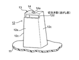
図2および図3に示すように、キッキングプレート11の裏面に、断面略コ字状の縦壁12を一体に設け、縦壁部12の先端側には、キッキングプレート11の裏面に沿うように一体のクリップ着座部13が形成されている。
As shown in FIGS. 2 and 3, a
クリップ着座部13には、縦壁部12の開口部側に開放されたクリップ係合孔14が形成されており、クリップ係合孔14の縦壁12の開口側先端部は、開口狭窄部14aに形成されている。
The
縦壁部12の背面壁12aには、キッキングプレート11の裏面に沿う方向を長手方向にした長溝12bが形成されている。
A
長溝12bは、クリップ係合孔14に開口狭窄部14a側からクリップ15の軸部15aを挿入して、クリップ15をクリップ着座部13に装着する場合、クリップ15の一対の係合フランジ部15b、15cのうちクリップ着座部13の内壁側に位置する係合フランジ部15bが挿入されて、縦壁部12の内壁側より外壁側に延在させる逃がし部を形成することになる。
When the
したがって、係合フランジ部15bは、長溝12b内において、縦壁部12の背面壁12aの板厚内に収まり、背面壁12aより外部部は突出していない。
Therefore, the
但し、このような構成に限定されるものでなく、図4に示すように、係合フランジ部15bが縦壁簿の背面壁12aより外方に突出させてもよい。
However, it is not limited to such a configuration, and as shown in FIG. 4, the
このように構成することによって、たとえクリップ着座部13における縦壁12から先端部までの全長を短く形成しても、係合フランジ部15bが長溝12b内に挿入されて逃すことができるので、係合フランジ15cと同様にクリップ15の軸部15aは縦壁12側にずれることになり、両係合フランジ15b、15cにおけるクリップ着座部への係合スペースを広くとることができ、結果的に、クリップ15を軸部15aとクリップ取付け孔の大きさの差分移動可能にすることができ、キッキングプレート11の熱収縮を吸収することができるとともに、スライド駒6のスライド量を確保することができ、たとえ、クリップ着座部13を形成するためのスライド駒のスライド線上に突起などが存在していたとしても、クリップ着座部13をキッキングプレート11に一体に形成することができ、止め点廃止などの処置をとる必要もないことになる。
With such a configuration, even if the entire length from the
さらに、クリップ着座部13は、縦壁部12の背面壁12aに長溝12bが設けられたとしても、縦壁12をコ字状に形成して、背面壁12aとともに両側面壁12cが連続して形成した3方壁に支持されていることになって、高荷重により支えられていることになる。
Furthermore, even if the
なお、クリップ15の軸部15aには、係合フランジ部15cより車体側の取付け孔(不図示)に係合するクリップ部15d側に、車体に弾接着座する舌片部15eがさらに形成されている。
The
図5は本発明のさらに別の実施の形態を示しており、図5によれば、上記実施の形態における長溝12bに代えて、縦壁部12とクリップ着座部13とがなす角部を切り欠いて形成した切欠き部12dにより、クリップ15のフランジ部12bの逃がし部を形成したものであり、上記実施の形態と同様の効果を発揮するものである。
FIG. 5 shows still another embodiment of the present invention. According to FIG. 5, a corner formed by the
なお、上記実施の形態においては、内装部品としてキッキングプレートを例に説明したが、本発明は、これに限定されるものではなく、例えばセンターピラートリム、リヤトリム、ラゲージサイドトリム或いはドアトリム等その他の内装部品に施用することができる。 In the above embodiment, the kicking plate has been described as an example of the interior part. However, the present invention is not limited to this, and other interior parts such as a center pillar trim, a rear trim, a luggage side trim, or a door trim, for example. Can be applied.
以上説明したように、本発明は、たとえ、クリップ着座部の全長を短く設定したとしても、係合フランジ部を逃がし部に挿入して縦壁部の内壁より外壁部側に延在させることによって、クリップ着座部への係合フランジ部の係合スペースが十分確保でき、クリップを軸部とクリップ取付け孔の大きさの差分移動可能にすることができて、内装部品の熱収縮を吸収することができ、しかも、クリップ着座部の全長を短くすることによって、スライド駒のスライド量も十分確保することができるために、自動車のキッキングプレート、センターピラートリム、リヤピラートリム或いはドアトリム等の内装部品を車体に装着するためのクリップを着座装着させるためのクリップ着座構造等に好適である。 As described above, even if the overall length of the clip seating portion is set to be short, the present invention inserts the engaging flange portion into the escape portion and extends from the inner wall of the vertical wall portion to the outer wall portion side. It is possible to secure a sufficient engagement space of the engagement flange portion to the clip seating portion, to enable the differential movement of the size of the shaft portion and the clip mounting hole, and to absorb the heat shrinkage of the interior part In addition, by shortening the overall length of the clip seating part, the sliding amount of the slide piece can be secured sufficiently. It is suitable for a clip seating structure or the like for seating and mounting a clip for doing so.
11 キッキングプレート(内装部品)
12 縦壁部
12a 背面壁
12b 長溝(逃がし部)
12d 切欠き部(逃がし部)
13 クリップ着座部
14 クリップ係合孔
15 クリップ
15a 軸部
15b、15c 係合フランジ部
11 Kicking plate (interior parts)
12
12d Notch (Relief)
13
Claims (1)
A clip seating portion is formed on the back surface of the interior part through a vertical wall portion, a clip locking hole for engaging and holding the clip is formed in the clip seating portion, and the shaft portion of the clip is inserted into the clip locking hole. A clip seating structure configured to attach the clip to the clip seating portion by sandwiching the inner and outer surfaces of the clip seating portion by a pair of engaging flange portions formed on the shaft portion; An escape portion for inserting an engagement flange portion positioned on the inner wall side of the clip seating portion of the pair of engagement flange portions into the vertical wall portion and extending from the inner wall side of the vertical wall portion to the outer wall side. A clip seating structure characterized by being formed.
Priority Applications (1)
| Application Number | Priority Date | Filing Date | Title |
|---|---|---|---|
| JP2004118683A JP2005299839A (en) | 2004-04-14 | 2004-04-14 | Clip seating structure |
Applications Claiming Priority (1)
| Application Number | Priority Date | Filing Date | Title |
|---|---|---|---|
| JP2004118683A JP2005299839A (en) | 2004-04-14 | 2004-04-14 | Clip seating structure |
Publications (1)
| Publication Number | Publication Date |
|---|---|
| JP2005299839A true JP2005299839A (en) | 2005-10-27 |
Family
ID=35331607
Family Applications (1)
| Application Number | Title | Priority Date | Filing Date |
|---|---|---|---|
| JP2004118683A Pending JP2005299839A (en) | 2004-04-14 | 2004-04-14 | Clip seating structure |
Country Status (1)
| Country | Link |
|---|---|
| JP (1) | JP2005299839A (en) |
Cited By (2)
| Publication number | Priority date | Publication date | Assignee | Title |
|---|---|---|---|---|
| US10894517B2 (en) | 2019-05-03 | 2021-01-19 | Ford Global Technologies, Llc | Doghouse retainer, door assembly incorporating that doghouse retainer and method of adjusting a gap between a first component and a second component |
| US12172586B2 (en) | 2022-05-17 | 2024-12-24 | Ford Global Technologies, Llc | Vehicle trim assembly with interchangeable attachment features |
-
2004
- 2004-04-14 JP JP2004118683A patent/JP2005299839A/en active Pending
Cited By (2)
| Publication number | Priority date | Publication date | Assignee | Title |
|---|---|---|---|---|
| US10894517B2 (en) | 2019-05-03 | 2021-01-19 | Ford Global Technologies, Llc | Doghouse retainer, door assembly incorporating that doghouse retainer and method of adjusting a gap between a first component and a second component |
| US12172586B2 (en) | 2022-05-17 | 2024-12-24 | Ford Global Technologies, Llc | Vehicle trim assembly with interchangeable attachment features |
Similar Documents
| Publication | Publication Date | Title |
|---|---|---|
| JP2551386Y2 (en) | Mounting structure for automotive molding | |
| JP2007504032A (en) | Vehicle body panel with integral clip | |
| JP2005113953A (en) | Cable clamp | |
| JP2018090135A (en) | Body structure | |
| JP2005299839A (en) | Clip seating structure | |
| JP5331612B2 (en) | Metal clip mounting structure | |
| JP3711856B2 (en) | Decoration member mounting structure | |
| JP2021084561A (en) | Vehicle front part structure | |
| JP2008012953A (en) | Interior part for automobile | |
| JP2014218220A (en) | Door trim for vehicle | |
| JP4462974B2 (en) | Pillar garnish assembly structure | |
| JP2008032040A (en) | Clip and mounting structure using clip | |
| JP3325515B2 (en) | Mounting structure between members and pocket structure of automotive door trim using this mounting structure | |
| JP7272169B2 (en) | Body side structure | |
| JP2009154772A (en) | Glass run | |
| JP2006044589A (en) | Coupling structure for interior component | |
| JP2006336748A (en) | Resin molding mounting structure | |
| JP2000081013A (en) | Clip mounting seat of interior trim part for vehicle | |
| JP2004345441A (en) | Vehicle overhead console structure | |
| JP7161705B2 (en) | vehicle garnish | |
| JP3983442B2 (en) | Automotive door trim structure | |
| JP4234641B2 (en) | Mounting structure for vehicle parts | |
| JP7234786B2 (en) | Mounting structure of vehicle exterior member | |
| JP2558661Y2 (en) | Glove box tray mounting structure | |
| JP4080834B2 (en) | Mounting structure for resin parts for vehicles |
Legal Events
| Date | Code | Title | Description |
|---|---|---|---|
| A621 | Written request for application examination |
Free format text: JAPANESE INTERMEDIATE CODE: A621 Effective date: 20070405 |
|
| A977 | Report on retrieval |
Effective date: 20090731 Free format text: JAPANESE INTERMEDIATE CODE: A971007 |
|
| A131 | Notification of reasons for refusal |
Effective date: 20091104 Free format text: JAPANESE INTERMEDIATE CODE: A131 |
|
| A02 | Decision of refusal |
Effective date: 20100302 Free format text: JAPANESE INTERMEDIATE CODE: A02 |