JP2005299830A - Torque converter - Google Patents
Torque converter Download PDFInfo
- Publication number
- JP2005299830A JP2005299830A JP2004118278A JP2004118278A JP2005299830A JP 2005299830 A JP2005299830 A JP 2005299830A JP 2004118278 A JP2004118278 A JP 2004118278A JP 2004118278 A JP2004118278 A JP 2004118278A JP 2005299830 A JP2005299830 A JP 2005299830A
- Authority
- JP
- Japan
- Prior art keywords
- hub
- stator
- impeller
- pump
- torque converter
- Prior art date
- Legal status (The legal status is an assumption and is not a legal conclusion. Google has not performed a legal analysis and makes no representation as to the accuracy of the status listed.)
- Granted
Links
Images
Classifications
-
- F—MECHANICAL ENGINEERING; LIGHTING; HEATING; WEAPONS; BLASTING
- F16—ENGINEERING ELEMENTS AND UNITS; GENERAL MEASURES FOR PRODUCING AND MAINTAINING EFFECTIVE FUNCTIONING OF MACHINES OR INSTALLATIONS; THERMAL INSULATION IN GENERAL
- F16H—GEARING
- F16H41/00—Rotary fluid gearing of the hydrokinetic type
- F16H41/24—Details
- F16H2041/246—Details relating to one way clutch of the stator
Landscapes
- Control Of Fluid Gearings (AREA)
Abstract
Description
本発明は,車両や産業機械に使用されるトルクコンバータに関し,特に,入力軸に結合されるポンプ羽根車と,このポンプ羽根車に対置されて出力軸が結合されるタービン羽根車と,それらポンプ羽根車及びタービン羽根車の内周部間に配置されるステータ羽根車とを備え,このステータ羽根車のハブ(以下,ステータハブという。)と,その中心部に配置されるステータ軸との間に介装されるフリーホイールが,ステータハブに結合されるアウタレース,ステータ軸に結合されるインナレース,その両レース間に介装される環状配列の一方向クラッチ素子群及び,この一方向クラッチ素子群を保持するケージより構成され,ポンプ羽根車のハブ(以下,ポンプハブという。)とタービン羽根車のハブ(以下,タービンハブという。)との間で一対のスラストニードルベアリングを介してステータ羽根車の軸方向移動を規制するようにしたトルクコンバータの改良に関する。 The present invention relates to a torque converter used in a vehicle or an industrial machine, and in particular, a pump impeller coupled to an input shaft, a turbine impeller opposed to the pump impeller and coupled to an output shaft, and the pumps. A stator impeller disposed between the inner peripheral portions of the impeller and the turbine impeller, and between a hub of the stator impeller (hereinafter referred to as a stator hub) and a stator shaft disposed at the center thereof. An interlaced freewheel includes an outer race coupled to the stator hub, an inner race coupled to the stator shaft, a one-way clutch element group arranged annularly between the two races, and the one-way clutch element group. It is made up of a cage that holds the space between the pump impeller hub (hereinafter referred to as the pump hub) and the turbine impeller hub (hereinafter referred to as the turbine hub). An improvement of the torque converter so as to restrict the axial movement of the stator impeller via a pair of thrust needle bearing.
かゝるトルクコンバータは,例えば特開2003−343690号公報に開示されているように,既に知られている。 Such a torque converter is already known as disclosed in, for example, Japanese Patent Laid-Open No. 2003-343690.
従来のかゝるトルクコンバータでは,フリーホイールのアウタレース及びケージの一端を支承する端壁をステータハブに一体に形成する一方,ステータハブ内には,アウタレースの外端面に当接すると共に,ケージの他端部を外側方から押さえるべくアウタレースの内周面に嵌合する端板を配設し,前記端壁とポンプハブとの間,並びに前記端板とステータハブとの間に前記一対のスラストニードルベアリングを介装している。したがって,前記一対のスラストニードルベアリングは,フリーホイールのアウタレース及びケージを軸方向で保持する,ステータハブの端壁及び端板の両外側に配置されることになるから,これらスラストニードルベアリングの両外側に配置されるポンプハブ及びタービンハブの間隔が広がってしまい,これがトルクコンバータ全体の軸方向寸法の短縮化の障害となっている。 In the conventional torque converter, an end wall for supporting one end of the freewheel outer race and the cage is formed integrally with the stator hub, while the stator hub contacts the outer end surface of the outer race and the other end of the cage. An end plate fitted to the inner peripheral surface of the outer race is disposed to be pressed from the outside, and the pair of thrust needle bearings are interposed between the end wall and the pump hub and between the end plate and the stator hub. ing. Accordingly, the pair of thrust needle bearings are disposed on both outer sides of the end wall and the end plate of the stator hub that hold the outer race and the cage of the free wheel in the axial direction. The distance between the pump hub and the turbine hub to be arranged widens, which is an obstacle to shortening the axial dimension of the entire torque converter.
本発明は,かゝる事情に鑑みてなされたもので,ポンプハブ及びタービンハブの間隔を狭めることができて,軸方向寸法の短縮化を可能にした前記トルクコンバータを提供することを目的とする。 The present invention has been made in view of such circumstances, and an object of the present invention is to provide the torque converter capable of reducing the distance between the pump hub and the turbine hub and shortening the axial dimension. .
上記目的を達成するために,本発明は,入力軸に結合されるポンプ羽根車と,このポンプ羽根車に対置されて出力軸が結合されるタービン羽根車と,それらポンプ羽根車及びタービン羽根車の内周部間に配置されるステータ羽根車とを備え,このステータ羽根車のハブ(以下,ステータハブという。)と,その中心部に配置されるステータ軸との間に介装されるフリーホイールが,ステータハブに結合されるアウタレース,ステータ軸に結合されるインナレース,その両レース間に介装される環状配列の一方向クラッチ素子群及び,この一方向クラッチ素子群を保持するケージより構成され,ポンプ羽根車のハブ(以下,ポンプハブという。)とタービン羽根車のハブ(以下,タービンハブという。)との間で一対のスラストニードルベアリングを介してステータ羽根車の軸方向移動を規制するようにしたトルクコンバータにおいて,前記フリーホイールのアウタレースを,その軸方向両端面が露出するようにしてステータハブの内周に固着し,このアウタレースと,ポンプハブ及びタービンハブ間に前記一対のスラストニードルベアリングを,それぞれのニードルローラ群がアウタレースの両端面に接するように介装し,これらスラストニードルベアリングの内周側に,ポンプハブ及びタービンハブにそれぞれ当接して前記ケージの軸方向移動を規制する一対の端板を配設したことを第1の特徴とするトルクコンバータ。 To achieve the above object, the present invention provides a pump impeller coupled to an input shaft, a turbine impeller coupled to the pump impeller and coupled to an output shaft, and the pump impeller and turbine impeller. A free wheel that is interposed between a hub of the stator impeller (hereinafter referred to as a stator hub) and a stator shaft that is disposed in the center of the stator impeller. Is composed of an outer race coupled to the stator hub, an inner race coupled to the stator shaft, a one-way clutch element group arranged in an annular arrangement between the both races, and a cage for holding the one-way clutch element group. , A pair of thrust needle bearings between a hub of a pump impeller (hereinafter referred to as a pump hub) and a hub of a turbine impeller (hereinafter referred to as a turbine hub). In the torque converter that regulates the axial movement of the stator impeller via the hub, the outer race of the free wheel is fixed to the inner periphery of the stator hub so that both end faces in the axial direction are exposed. The pair of thrust needle bearings are interposed between the pump hub and the turbine hub so that the respective needle roller groups are in contact with both end faces of the outer race, and the pump hub and the turbine hub are respectively disposed on the inner peripheral side of the thrust needle bearing. A torque converter characterized in that a pair of end plates that contact and regulate axial movement of the cage is provided.
尚,前記入力軸は,後述する本発明の実施例中のクランク軸に対応し,一方向クラッチ素子はスプラグ17に対応する。
The input shaft corresponds to a crankshaft in an embodiment of the present invention described later, and the one-way clutch element corresponds to a
また本発明は,第1の特徴に加えて,ステータハブの内周面に雌スプラインと,この雌スプラインの一端に隣接する環状の支持壁とを形成する一方,前記アウタレースには,前記環状の支持壁の内周面に嵌合する同心位置決め部と,前記雌スプラインに嵌合して前記支持壁の内端面に当接する雄スプラインとを形成し,前記支持壁と協働して前記雄スプラインの軸方向移動を規制する係止部材をステータハブに設けたことを第2の特徴とする。 According to the present invention, in addition to the first feature, a female spline and an annular support wall adjacent to one end of the female spline are formed on the inner peripheral surface of the stator hub, while the outer race has the annular support. A concentric positioning portion fitted to the inner peripheral surface of the wall and a male spline fitted to the female spline and abutted against the inner end surface of the support wall; and in cooperation with the support wall, A second feature is that a locking member for restricting movement in the axial direction is provided on the stator hub.
さらに本発明は,第1又は第2の特徴に加えて,前記各端板には,それのポンプハブ又はタービンハブに支承される外端面で半径方向に延びる複数のオイル溝を設けたことを第3の特徴とする。 Further, in addition to the first or second feature, the present invention is characterized in that each end plate is provided with a plurality of oil grooves extending radially in the outer end surface supported by the pump hub or the turbine hub. Three features.
さらにまた本発明は,第3の特徴に加えて,前記各端板には,前記オイル溝を前記アウタレース内に連通する複数のオイル孔とを設けたことを第4の特徴とする。 Furthermore, in addition to the third feature, the present invention has a fourth feature in which each end plate is provided with a plurality of oil holes that communicate the oil groove with the outer race.
本発明の第1の特徴によれば,各一対のスラストニードルベアリング及び端板が,互いに半径方向に同心配置されることになり,ポンプハブ及びタービンハブの間隔を充分に狭めて,トルクコンバータ全体の軸方向寸法の短縮化を図ることができる。 According to the first aspect of the present invention, each pair of thrust needle bearings and end plates are arranged concentrically in the radial direction, and the distance between the pump hub and the turbine hub is sufficiently narrowed, so that the entire torque converter is The axial dimension can be shortened.
また本発明の第2の特徴によれば,アウタレースのステータハブに対する同心精度を確保しつゝ,両者の結合を簡単,確実に行うことができ,組立性が良好であり,しかもアウタレースの両端面を,前記スラストニードルベアリングに支承させるべく露出させることができる。 In addition, according to the second feature of the present invention, the concentric accuracy of the outer race with respect to the stator hub can be ensured, the two can be connected easily and reliably, the assemblability is good, and both end faces of the outer race are secured. , And can be exposed to be supported by the thrust needle bearing.
さらに本発明の第3の特徴によれば,作動オイルがオイル溝及びスラストニードルベアリングを通してトルクコンバータの循環回路に出入りすることになり,スラストニードルベアリングのみならず,端板とポンプハブ及びタービンハブとの各当接面をも良好に潤滑することができる。 Further, according to the third feature of the present invention, the working oil enters and exits the circulation circuit of the torque converter through the oil groove and the thrust needle bearing, and not only the thrust needle bearing but also the end plate, the pump hub, and the turbine hub. Each contact surface can be well lubricated.
さらにまた本発明の第4の特徴によれば,オイル溝を通る作動オイルの一部がオイル孔からアウタレース内に流入して,プラグ17,17…群などフリーホイール11内部を確実に潤滑することができる。
Furthermore, according to the fourth feature of the present invention, a part of the working oil passing through the oil groove flows into the outer race from the oil hole, and the inside of the
本発明の実施の形態を,添付図面に示す本発明の実施例に基づいて以下に説明する。 DESCRIPTION OF THE PREFERRED EMBODIMENTS Embodiments of the present invention will be described below based on examples of the present invention shown in the accompanying drawings.
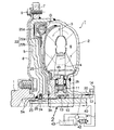
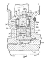
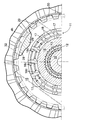
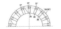
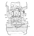
図1は本発明の第1実施例に係るトルクコンバータの縦断側面図,図2は図1の2部拡大図,図3は図2の3−3線断面図,図4は図2におけるフリーホイールの端板の外側端面図,図5は本発明の第2実施例を示す,図2との対応図である。
1 is a longitudinal side view of a torque converter according to a first embodiment of the present invention, FIG. 2 is an enlarged view of
先ず,本発明の第1実施例の説明より始める。図1において,トルクコンバータTは,ポンプ羽根車2と,それと対置されるタービン羽根車3と,それらの内周部間に配置されるステータ羽根車4とを備え,これら羽根車2,3,4間には作動オイルによる動力伝達のための循環回路6が画成される。
First, the description starts with the description of the first embodiment of the present invention. In FIG. 1, the torque converter T includes a
ポンプ羽根車2には,タービン羽根車3の外側面を覆うサイドカバー5が溶接により一体的に連設される。サイドカバー5の外周面には,始動用のリングギヤ7が嵌合して溶接されており,このリングギヤ7に,クランク軸1に結合した駆動板8がボルト9で固着される。タービン羽根車3のハブ3h(以下,タービンハブ3hという。)とサイドカバー5との間にスラストニードルベアリング26が介裝される。
A
トルクコンバータTの中心部にクランク軸1と同軸上に並ぶ出力軸10が配置され,この出力軸10は,タービンハブ3hにスプライン嵌合されると共に,サイドカバー5中心部の支持筒5aに軸受ブッシュ23を介して回転自在に支承される。出力軸10は図示しない多段変速機の主軸となる。
An
出力軸10の外周には,ステータ羽根車4のハブ4h(以下,ステータハブ4hという。)をフリーホイール11を介して支承する中空円筒状のステータ軸12が配置され,これら出力軸10及びステータ軸12間には,それらの相対回転を許容するラジアルニードルベアリング13が介裝される。ステータ軸12の外端部はミッションケース14に回転不能に支持される。
A hollow
図2及び図3に明示するように,フリーホイール11は,ステータハブ4hの内周面に圧入により結合されるアウタレース15と,ステータ軸12の外周にスプライン結合されるインナレース16と,これらレース15,16間に介裝される環状配列のスプラグ17,17…群と,このスプラグ17,17…群を保持する環状配列の保持窓18c,18c…群を有する環状のケージ18とからなっている。
As clearly shown in FIGS. 2 and 3, the
ステータ羽根車4は,Al合金等の軽合金製であり,そのステータハブ4hの内周面に鋼鉄製のアウタレース15が次のように取り付けられる。
The stator impeller 4 is made of a light alloy such as an Al alloy, and a steel
即ち,ステータハブ4hの内周には雌スプライン27と,この雌スプライン27の一端に隣接する環状の支持壁28とが形成される。また,アウタレース15には,前記環状の支持壁28の内周面に嵌合する同心位置決め部29と,前記雌スプライン27に嵌合して前記支持壁28の内端面に当接する雄スプライン30とが形成され,支持壁28と協働して雄スプライン30を軸方向に挟持するサークリップ32がステータハブ4hに係止される。こうして,ステータハブ4hの内周に取り付けられたアウタレース15は,軸方向両端面を露出させている。
That is, a
一方,インナレース16の軸方向両端部には,スプラグ17,17…群との接触部より小径の支持部16a,16aが形成され,これら支持部16a,16aには,前記ケージ18を挟んでその軸方向移動を規制する一対の環状の端板35,35′がそれぞれ回転可能に嵌合され,またこれら端板35,35′の外周には,一対のスラストニードルベアリング34,34′が配設される。一側のスラストニードルベアリング34及び端板35には,ポンプ羽根車2のハブ2h(以下,ポンプハブ2hという。)の内端面が,また他側のスラストニードルベアリング34′及び端板35′にはタービンハブ3hの内端面がそれぞれ対向配置され,これによってポンプハブ2h及びタービンハブ3hは,ステータハブ4hと固着したアウタレース15を一対のスラストニードルベアリング34,34′を介して軸方向に支承すると共に,一対の端板35,35′の軸方向移動を規制する。
On the other hand, support
上記スラストニードルベアリング34,34′は,何れも放射状配列のニードルローラ34a,34a…群と,これらニードルローラ35a,35a…群を保持するニードルケージ34aと,このニードルケージ34aの内周面に嵌合してニードルローラ34a,34a…群の外側面に接する硬質のスラスト板34cとからなっており,ニードルローラ34a,34a…群は,アウタレース15の対応する端面に転動可能に接し,スラスト板34cは,対応するポンプハブ2h又はタービンハブ3hの内端面に当接して軸方向移動が規制されるようになっている。而して,両スラストニードルベアリング34,34′は,ポンプハブ2h及びタービンハブ3h間でアウタレース15を軸方向定位置に保持し,また両端板35,35′は,ポンプハブ2h及びタービンハブ3h間でインナレース16及びケージ18を軸方向定位置に保持する。
The
図2及び図4に示すように,各端板35,35′の,ポンプハブ2h又はタービンハブ3hとの対向面には,放射状配置の複数のオイル溝36,36…が形成され,またこれらオイル溝36,36…をアウタレース15内に連通する複数のオイル孔37,37…が各端板35,35′に穿設される。
As shown in FIGS. 2 and 4, a plurality of radially arranged
再び図1において,ステータ軸12の外周には,ポンプ羽根車2に結合した補機駆動軸20が相対回転可能に配置され,この補機駆動軸20によって,トルクコンバータTに作動オイルを供給するオイルポンプ21が駆動されるようになっている。
Referring again to FIG. 1, an auxiliary
タービン羽根車3及びサイドカバー5には,前記循環回路6と外周部で連通するクラッチ室22画成され,このクラッチ室22には,タービン羽根車3及びサイドカバー5間を直結し得るロックアップクラッチLが設けられる。即ち,ロックアップクラッチLの主体をなすクラッチピストン25が,クラッチ室22をタービン羽根車3側の内側室22aとサイドカバー5側の外側室22bとに区画するようにクラッチ室22に配置される。クラッチピストン25は,その一端面に備えた摩擦ライニング25aをサイドカバー5内側壁に圧接させる接続位置と,その内壁から離間する非接続位置との間を軸方向に移動し得るように,タービンハブ3hの外周面に摺動可能に支承される。
The
またクラッチ室22には,クラッチピストン25及びタービン羽根車3間を緩衝的に連結する公知のトルクダンパDが配設される。
The
出力軸10の中心部には,横孔24及びスラストニードルベアリング26を介してクラッチ室22の外側室22bに連通する第1油路40が設けられる。また補機駆動軸20とステータ軸12との間には,前記オイル溝36,36…及びオイル孔37,37…を介して循環回路6の内周部に連通する第2油路41が画成され,これら第1油路40及び第2油路41は,ロックアップ制御弁42により,オイルポンプ21の吐出側とオイル溜め43とに交互に接続されるようになっている。
A
次に,この実施例の作用について説明する。 Next, the operation of this embodiment will be described.
エンジンのアイドリングないし極低速運転域では,ロックアップ制御弁42は,図1に示すように,第1油路40をオイルポンプ21の吐出側に接続する一方,第2油路41をオイル溜め43に接続するように,図示しない電子制御ユニットにより制御される。したがって,エンジンのクランク軸1の出力トルクが駆動板8,サイドカバー5,ポンプ羽根車2へと伝達して,それを回転駆動し,更にオイルポンプ21をも駆動すると,オイルポンプ21の吐出作動オイルがロックアップ制御弁42から第1油路40,横孔24及びスラストニードルベアリング26,クラッチ室22の外側室22b,内側室22aを順次経て循環回路6に流入し,該回路6を満たした後,スラストニードルベアリング34,34′及びオイル溝36,36…を経て第2油路41に移り,ロックアップ制御弁42からオイル溜め43に還流する。
In the engine idling or extremely low speed operation region, the
その間,スラストニードルベアリング34,34′は,それらを通過する作動オイルによって潤滑され,またオイル溝36,36…を通過する作動オイルによって端板35,35′とポンプハブ2h及びタービンハブ3hとの当接面が潤滑され,さらにオイル溝36,36…を通過する作動オイルの一部がオイル孔37,37…を通してアウタレース15内に流入することにより,プラグ17,17…群などフリーホイール11内部が潤滑される。
Meanwhile, the
而して,クラッチ室22では,上記のような作動オイルの流れにより外側室22bの方が内側室22aよりも高圧となり,その圧力差によりクラッチピストン25がサイドカバー5の内壁から引き離される方向へ押圧されるので,ロックアップクラッチLは非接続状態となっており,ポンプ羽根車2及びタービン羽根車3の相対回転を許容している。したがって,クランク軸1からポンプ羽根車2が回転駆動されると,循環回路5を満たしている作動オイルが矢印のように循環回路5を循環することにより,ポンプ羽根車3の回転トルクをタービン羽根車4に伝達し,出力軸10を駆動する。
Thus, in the
このとき,ポンプ羽根車2及びタービン羽根車3間でトルクの増幅作用が生じていれば,それに伴う反力がステータ羽根車4に負担され,ステータ羽根車4は,フリーホイール11のロック作用により,即ちスプラグ17,17…群がアウタレース15及びインナレース16の相対回転を阻止するように両レース15,16間にロックされることにより,ステータ軸12に連結,固定される。
At this time, if a torque amplifying action is generated between the
トルク増幅作用を終えると,ステータ羽根車4は,これが受けるトルク方向の反転により,フリーホイール11が空転すること,即ちスプラグ17,17…群が両レース15,16の相対回転を許容することでポンプ羽根車2及びタービン羽根車3と共に同一方向へ回転するようになる。
When the torque amplifying operation is finished, the stator impeller 4 is rotated by the reversal of the torque direction received by the stator impeller 4, that is, the
トルクコンバータTがこのようなカップリング状態となったところで,電子制御ユニットによりロックアップ制御弁42を切換える。その結果,オイルポンプ21の吐出作動オイルは,先刻とは反対に,ロックアップ制御弁42から第2油路41を経て循環回路6に流入して,該回路6を満たした後,クラッチ室22の内側室22aに移って,該内側室22aをも満たす。一方,クラッチ室22の外側室22bは,第1油路40及びロックアップ制御弁42を介してオイル溜め43に開放されるので,クラッチ室22では,内側室22aの方が外側室22bよりも高圧となり,クラッチピストン25は,その圧力差によりサイドカバー5側に押圧され,摩擦ライニング25aをサイドカバー5の内側壁に圧接させ,ロックアップクラッチLは接続状態となる。すると,クランク軸1からポンプ羽根車2に伝達した回転トルクは,サイドカバー5からクラッチピストン25,トルクダンパDを介してタービン羽根車3に機械的に伝達することになるから,ポンプ羽根車2及びタービン羽根車4は直結の状態となり,クランク軸1の出力トルクを出力軸10に効率良く伝達することができ,燃費の低減を図ることができる。
When the torque converter T enters such a coupling state, the
ところで,このようなトルクコンバータTにおいて,フリーホイール11のアウタレース15を,その両端面が露出するようにしてタービンハブ3hに固着し,このアウタレース15と,ポンプハブ2h及びタービンハブ3h間に一対のスラストニードルベアリング34,34′を,それぞれのニードルローラ34a,34a…群がアウタレース15の両端面に接するように介装し,これらスラストニードルベアリング34,34′の内周側に,ポンプハブ2h及びタービンハブ3hにそれぞれ当接してフリーホイール11のケージ18の軸方向移動を規制する一対の端板35,35′を配設したので,各一対のスラストニードルベアリング34,34′及び端板35,35′は,互いに半径方向に同心配置されることになり,ポンプハブ2h及びタービンハブ3hの間隔を充分に狭めて,トルクコンバータT全体の軸方向寸法の短縮化を図ることができる。
By the way, in such a torque converter T, the
またアウタレース15のステータハブ4hへの固着構造は,ステータハブ4hの内周面に雌スプライン27と,この雌スプライン27の一端に隣接する環状の支持壁28とを形成する一方,前記アウタレース15には,前記環状の支持壁28の内周面に嵌合する同心位置決め部29と,前記雌スプライン27に嵌合して前記支持壁28の内端面に当接する雄スプライン30とを形成し,前記支持壁28と協働して雄スプライン30を挟持するサークリップ32をステータハブ4hに係止して構成されるので,アウタレース15のステータハブ4hに対する同心精度を確保しつゝ,両者の結合を簡単,確実に行うことができ,組立性が良好であり,しかもアウタレース15の両端面を,前記スラストニードルベアリング34,34′に支承させるべく露出させることができる。
The
またアウタレース15と,ポンプハブ2h及びタービンハブ3hとの各間に介装される一対のスラストニードルベアリング34,34′の半径方向内側に,フリーホイール11の一対の端板35,35′を配設し,これら端板35,35′の,ポンプハブ2h及びタービンハブ3hとの対向面に放射状の複数のオイル溝36,36…を形成したことにより,作動オイルがオイル溝36,36…及びスラストニードルベアリング34,34′を通してトルクコンバータTの循環回路6に出入りすることになり,スラストニードルベアリング34,34′の良好な潤滑状態を得ることができる他,端板35,35′とポンプハブ2h及びタービンハブ3hとの当接面をも良好に潤滑することができる。
A pair of
しかも端板35,35′には,上記オイル溝36,36…をアウタレース15内に連通する複数のオイル孔37,37…を設けたので,オイル溝36,36…を通る作動オイルの一部がオイル孔37,37…からアウタレース15内に流入して,プラグ17,17…群などフリーホイール11内部を確実に潤滑することができる。
In addition, since the
次に,図5に示す本発明の第2実施例について説明する。 Next, a second embodiment of the present invention shown in FIG. 5 will be described.
この第2実施例は,スラストニードルベアリング34,34′からスラスト板を取り去り,ニードルローラ34a,34a…群の外側面をもポンプハブ2h及びタービンハブ3hに直接接触させるようにしたものであり,その他の構成は,前実施例を同様の構成であるので,図中,前実施例と対応する部分については同一の符号を付して,その説明を省略する。
In the second embodiment, the thrust plate is removed from the
この第2実施例によれば,スラストニードルベアリング34,34′からスラスト板を取り去った分,ポンプハブ2h及びタービンハブ3hの間隔を狭めることができて,トルクコンバータTの軸方向寸法の更なる短縮化を図ることができる。
According to the second embodiment, the distance between the
本発明は上記実施例に限定されるものではなく,その要旨を逸脱しない範囲で種々の設計変更が可能である。 The present invention is not limited to the above embodiment, and various design changes can be made without departing from the scope of the invention.
T・・・・・・トルクコンバータ
1・・・・・・入力軸(エンジンのクランク軸)
2・・・・・・ポンプ羽根車
3・・・・・・タービン羽根車
4・・・・・・ステータ羽根車
10・・・・・出力軸
11・・・・・フリーホイール
12・・・・・ステータ軸
15・・・・・アウタレース
16・・・・・インナレース
17・・・・・一方向クラッチ素子(スプラグ)
18・・・・・ケージ
27・・・・・雌スプライン
28・・・・・支持壁
29・・・・・同心位置決め部
30・・・・・雄スプライン
32・・・・・係止部材(サークリップ)
34,34′・・・スラストニードルベアリング
35,35′・・・端板
T ... Torque converter 1 ... Input shaft (engine crankshaft)
2 ...
18 ...
34, 34 '...
Claims (4)
前記フリーホイール(11)のアウタレース(15)を,その軸方向両端面が露出するようにしてステータハブ(4h)の内周に固着し,このアウタレース(15)と,ポンプハブ(2h)及びタービンハブ(3h)間に前記一対のスラストニードルベアリング(34,34′)を,それぞれのニードルローラ(34a)群がアウタレース(15)の両端面に接するように介装し,これらスラストニードルベアリング(34,34′)の内周側に,ポンプハブ(2h)及びタービンハブ(3h)にそれぞれ当接して前記ケージ(18)の軸方向移動を規制する一対の端板(35,35′)を配設したことを特徴とするトルクコンバータ。 A pump impeller (2) coupled to the input shaft (1), a turbine impeller (3) coupled to the pump impeller (2) and coupled to the output shaft (10), and the pump impeller ( 2) and a stator impeller (4) disposed between the inner peripheral portions of the turbine impeller (3), a hub of the stator impeller (4) (hereinafter referred to as a stator hub) (4h), An outer race (15) coupled to the stator hub (4h), an inner race coupled to the stator shaft (12), and a free wheel (11) interposed between the stator shaft (12) disposed in the center. (16), a ring-shaped one-way clutch element (17, 17 ...) group interposed between the races (15, 16), and a cage for holding the one-way clutch element (17, 17 ...) group (18) A stator between a hub of the impeller (2) (hereinafter referred to as a pump hub) and a hub of the turbine impeller (3) (hereinafter referred to as a turbine hub) via a pair of thrust needle bearings (34, 34 '). In the torque converter designed to regulate the axial movement of the impeller (4),
The outer race (15) of the free wheel (11) is fixed to the inner periphery of the stator hub (4h) so that both end faces in the axial direction are exposed. The outer race (15), the pump hub (2h) and the turbine hub ( 3h), the pair of thrust needle bearings (34, 34 ') are interposed so that the respective needle rollers (34a) are in contact with both end faces of the outer race (15). And a pair of end plates (35, 35 ') that abut against the pump hub (2h) and the turbine hub (3h) to restrict the axial movement of the cage (18). Torque converter characterized by
ステータハブ(4h)の内周には,雌スプライン(27)と,この雌スプライン(27)の一端に隣接する環状の支持壁(28)とを形成する一方,前記アウタレース(15)には,前記環状の支持壁(28)の内周面に嵌合する同心位置決め部(29)と,前記雌スプライン(27)に嵌合して前記支持壁(28)の内端面に当接する雄スプライン(30)とを形成し,前記支持壁(28)と協働して前記前記雌スプライン(27)の軸方向移動を規制する係止部材(32)をステータハブ(4h)に設けたことを特徴とするトルクコンバータ。 The torque converter according to claim 1,
On the inner periphery of the stator hub (4h), a female spline (27) and an annular support wall (28) adjacent to one end of the female spline (27) are formed, while the outer race (15) A concentric positioning portion (29) fitted to the inner peripheral surface of the annular support wall (28), and a male spline (30) fitted to the female spline (27) and abutted against the inner end surface of the support wall (28) And a locking member (32) for restricting the axial movement of the female spline (27) in cooperation with the support wall (28) is provided on the stator hub (4h). Torque converter.
前記各端板(35,35′)には,それのポンプハブ(2h)又はタービンハブ(3h)に支承される外端面で半径方向に延びる複数のオイル溝(36,36…)を設けたことを特徴とするトルクコンバータ。 The torque converter according to claim 1 or 2,
Each of the end plates (35, 35 ') is provided with a plurality of oil grooves (36, 36 ...) extending in the radial direction at the outer end surface supported by the pump hub (2h) or turbine hub (3h) thereof. Torque converter characterized by
前記各端板(35,35′)には,前記オイル溝(36,36…)を前記アウタレース(15)内に連通する複数のオイル孔(37)とを設けたことを特徴とするトルクコンバータ。 The torque converter according to claim 3,
A torque converter characterized in that each end plate (35, 35 ') is provided with a plurality of oil holes (37) communicating the oil grooves (36, 36 ...) into the outer race (15). .
Priority Applications (1)
| Application Number | Priority Date | Filing Date | Title |
|---|---|---|---|
| JP2004118278A JP4537752B2 (en) | 2004-04-13 | 2004-04-13 | Torque converter |
Applications Claiming Priority (1)
| Application Number | Priority Date | Filing Date | Title |
|---|---|---|---|
| JP2004118278A JP4537752B2 (en) | 2004-04-13 | 2004-04-13 | Torque converter |
Publications (2)
| Publication Number | Publication Date |
|---|---|
| JP2005299830A true JP2005299830A (en) | 2005-10-27 |
| JP4537752B2 JP4537752B2 (en) | 2010-09-08 |
Family
ID=35331600
Family Applications (1)
| Application Number | Title | Priority Date | Filing Date |
|---|---|---|---|
| JP2004118278A Expired - Lifetime JP4537752B2 (en) | 2004-04-13 | 2004-04-13 | Torque converter |
Country Status (1)
| Country | Link |
|---|---|
| JP (1) | JP4537752B2 (en) |
Cited By (4)
| Publication number | Priority date | Publication date | Assignee | Title |
|---|---|---|---|---|
| JP2007315496A (en) * | 2006-05-25 | 2007-12-06 | Yutaka Giken Co Ltd | Outboard motor |
| EP1903258A3 (en) * | 2006-09-25 | 2010-04-14 | Mazda Motor Corporation | Torque converter |
| WO2010125640A1 (en) * | 2009-04-28 | 2010-11-04 | トヨタ自動車株式会社 | Oil path structure for chain-driven oil pump |
| KR101417352B1 (en) * | 2012-10-05 | 2014-07-08 | 현대 파워텍 주식회사 | Hydraulic pressure oil passage structure for automatic transmission |
Citations (4)
| Publication number | Priority date | Publication date | Assignee | Title |
|---|---|---|---|---|
| JPS628434U (en) * | 1985-06-28 | 1987-01-19 | ||
| JPS6282453U (en) * | 1985-11-12 | 1987-05-26 | ||
| JPH0960707A (en) * | 1995-08-23 | 1997-03-04 | Toyota Motor Corp | Torque converter with lockup mechanism |
| JP2002005260A (en) * | 2000-06-19 | 2002-01-09 | Aisin Aw Co Ltd | Torque converter |
-
2004
- 2004-04-13 JP JP2004118278A patent/JP4537752B2/en not_active Expired - Lifetime
Patent Citations (4)
| Publication number | Priority date | Publication date | Assignee | Title |
|---|---|---|---|---|
| JPS628434U (en) * | 1985-06-28 | 1987-01-19 | ||
| JPS6282453U (en) * | 1985-11-12 | 1987-05-26 | ||
| JPH0960707A (en) * | 1995-08-23 | 1997-03-04 | Toyota Motor Corp | Torque converter with lockup mechanism |
| JP2002005260A (en) * | 2000-06-19 | 2002-01-09 | Aisin Aw Co Ltd | Torque converter |
Cited By (8)
| Publication number | Priority date | Publication date | Assignee | Title |
|---|---|---|---|---|
| JP2007315496A (en) * | 2006-05-25 | 2007-12-06 | Yutaka Giken Co Ltd | Outboard motor |
| EP1903258A3 (en) * | 2006-09-25 | 2010-04-14 | Mazda Motor Corporation | Torque converter |
| US7866454B2 (en) | 2006-09-25 | 2011-01-11 | Mazda Motor Corporation | Torque converter |
| WO2010125640A1 (en) * | 2009-04-28 | 2010-11-04 | トヨタ自動車株式会社 | Oil path structure for chain-driven oil pump |
| JP5012912B2 (en) * | 2009-04-28 | 2012-08-29 | トヨタ自動車株式会社 | Oil path structure of chain drive type oil pump |
| US9003926B2 (en) | 2009-04-28 | 2015-04-14 | Toyota Jidosha Kabushiki Kaisha | Oil passage structure of chain-drive oil pump |
| US9273769B2 (en) | 2009-04-28 | 2016-03-01 | Toyota Jidosha Kabushiki Kaisha | Automatic transmission device for automobile |
| KR101417352B1 (en) * | 2012-10-05 | 2014-07-08 | 현대 파워텍 주식회사 | Hydraulic pressure oil passage structure for automatic transmission |
Also Published As
| Publication number | Publication date |
|---|---|
| JP4537752B2 (en) | 2010-09-08 |
Similar Documents
| Publication | Publication Date | Title |
|---|---|---|
| US7036306B2 (en) | One-way clutch | |
| JP3878796B2 (en) | Bearing structure | |
| JP2009243597A (en) | Starting device | |
| JP2007016833A (en) | Fluid transmission device | |
| CN101140027A (en) | Stator supports for torque converters | |
| US6547051B2 (en) | Lock-up clutch of fluid transmission device | |
| JP2001241530A (en) | Torque converter | |
| US5928104A (en) | Supporting structure for one-way clutch | |
| JP4929947B2 (en) | Torque converter | |
| JP4537752B2 (en) | Torque converter | |
| JP4788545B2 (en) | Torque converter | |
| JP5123887B2 (en) | Fluid transmission device with lock-up clutch | |
| JP4537625B2 (en) | Fluid transmission device with lock-up clutch | |
| JP4021244B2 (en) | Torque converter | |
| JP4944459B2 (en) | Lock-up clutch for fluid transmission | |
| JP5123892B2 (en) | Torque converter | |
| JP2004156676A (en) | Power transmission for small vehicle | |
| JP4414205B2 (en) | Power transmission device for vehicle | |
| JP2527399Y2 (en) | Suspension of torque converter | |
| JP4980981B2 (en) | Stator support device in torque converter | |
| JP4282973B2 (en) | Power transmission device for small vehicles | |
| JP4167473B2 (en) | Torque converter | |
| JP2005133731A (en) | Torque converter | |
| JP4414203B2 (en) | Power transmission device for vehicle | |
| JP4537871B2 (en) | Fluid transmission device |
Legal Events
| Date | Code | Title | Description |
|---|---|---|---|
| A621 | Written request for application examination |
Free format text: JAPANESE INTERMEDIATE CODE: A621 Effective date: 20070208 |
|
| A977 | Report on retrieval |
Free format text: JAPANESE INTERMEDIATE CODE: A971007 Effective date: 20091022 |
|
| A131 | Notification of reasons for refusal |
Free format text: JAPANESE INTERMEDIATE CODE: A131 Effective date: 20091028 |
|
| A521 | Request for written amendment filed |
Free format text: JAPANESE INTERMEDIATE CODE: A523 Effective date: 20091228 |
|
| TRDD | Decision of grant or rejection written | ||
| A01 | Written decision to grant a patent or to grant a registration (utility model) |
Free format text: JAPANESE INTERMEDIATE CODE: A01 Effective date: 20100609 |
|
| A01 | Written decision to grant a patent or to grant a registration (utility model) |
Free format text: JAPANESE INTERMEDIATE CODE: A01 |
|
| A61 | First payment of annual fees (during grant procedure) |
Free format text: JAPANESE INTERMEDIATE CODE: A61 Effective date: 20100618 |
|
| FPAY | Renewal fee payment (event date is renewal date of database) |
Free format text: PAYMENT UNTIL: 20130625 Year of fee payment: 3 |
|
| R150 | Certificate of patent or registration of utility model |
Ref document number: 4537752 Country of ref document: JP Free format text: JAPANESE INTERMEDIATE CODE: R150 Free format text: JAPANESE INTERMEDIATE CODE: R150 |
|
| FPAY | Renewal fee payment (event date is renewal date of database) |
Free format text: PAYMENT UNTIL: 20130625 Year of fee payment: 3 |
|
| FPAY | Renewal fee payment (event date is renewal date of database) |
Free format text: PAYMENT UNTIL: 20140625 Year of fee payment: 4 |
|
| R250 | Receipt of annual fees |
Free format text: JAPANESE INTERMEDIATE CODE: R250 |
|
| R250 | Receipt of annual fees |
Free format text: JAPANESE INTERMEDIATE CODE: R250 |
|
| R250 | Receipt of annual fees |
Free format text: JAPANESE INTERMEDIATE CODE: R250 |
|
| R250 | Receipt of annual fees |
Free format text: JAPANESE INTERMEDIATE CODE: R250 |
|
| R250 | Receipt of annual fees |
Free format text: JAPANESE INTERMEDIATE CODE: R250 |
|
| R250 | Receipt of annual fees |
Free format text: JAPANESE INTERMEDIATE CODE: R250 |
|
| R250 | Receipt of annual fees |
Free format text: JAPANESE INTERMEDIATE CODE: R250 |
|
| R250 | Receipt of annual fees |
Free format text: JAPANESE INTERMEDIATE CODE: R250 |
|
| R250 | Receipt of annual fees |
Free format text: JAPANESE INTERMEDIATE CODE: R250 |
|
| R250 | Receipt of annual fees |
Free format text: JAPANESE INTERMEDIATE CODE: R250 |
|
| R250 | Receipt of annual fees |
Free format text: JAPANESE INTERMEDIATE CODE: R250 |
|
| EXPY | Cancellation because of completion of term |