JP2005299818A - Hydraulic pressing device - Google Patents
Hydraulic pressing device Download PDFInfo
- Publication number
- JP2005299818A JP2005299818A JP2004117842A JP2004117842A JP2005299818A JP 2005299818 A JP2005299818 A JP 2005299818A JP 2004117842 A JP2004117842 A JP 2004117842A JP 2004117842 A JP2004117842 A JP 2004117842A JP 2005299818 A JP2005299818 A JP 2005299818A
- Authority
- JP
- Japan
- Prior art keywords
- piston
- diameter chamber
- pressure
- hydraulic
- pump
- Prior art date
- Legal status (The legal status is an assumption and is not a legal conclusion. Google has not performed a legal analysis and makes no representation as to the accuracy of the status listed.)
- Pending
Links
- 239000007788 liquid Substances 0.000 claims abstract description 22
- 239000012530 fluid Substances 0.000 claims abstract description 11
- 238000003780 insertion Methods 0.000 description 23
- 230000037431 insertion Effects 0.000 description 23
- 239000003921 oil Substances 0.000 description 4
- 238000012856 packing Methods 0.000 description 4
- 239000010720 hydraulic oil Substances 0.000 description 3
- 230000008602 contraction Effects 0.000 description 2
- -1 and in many cases Substances 0.000 description 1
- 230000000694 effects Effects 0.000 description 1
- 230000004043 responsiveness Effects 0.000 description 1
Images
Landscapes
- Actuator (AREA)
- Fluid-Pressure Circuits (AREA)
Abstract
【課題】 公知の超磁歪ポンプは吐出量が微小流量であるため、超磁歪ポンプのストローク時間や出力(圧力)等に限界があり、それによる規制を受けるので使用する用途が限定されると言う問題点を解消し、充分に長いストロークを高速移動可能で大きな押付力を得ることのできる液圧式押付装置を提供する。
【解決手段】 リザーバタンクからの作動液をピストンとシリンダとからなる押付手段に管路を介して加圧供給する給液ポンプを備えた液圧式押圧装置において、前記給液ポンプからの作動圧液を蓄圧する蓄圧手段を管路内に備え、前記押付手段は、前記ピストンが減縮待機位置から第1伸長位置に摺動する際に前記管路に連通される小径室と、前記ピストンが第1伸長位置から最大伸長位置に摺動する際に前記管路に連通される大径室と、前記小径室から大径室への連通路を切換える切換え手段とを備えたもの。
【選択図】 図1PROBLEM TO BE SOLVED: There is a limit to the stroke time or output (pressure) of a giant magnetostrictive pump because the discharge amount of a known giant magnetostrictive pump is a minute flow rate, and the usage is limited because it is restricted by that. Provided is a hydraulic pressing device that solves the problems, can move a sufficiently long stroke at high speed and can obtain a large pressing force.
SOLUTION: In a hydraulic pressing device provided with a liquid supply pump for supplying hydraulic fluid from a reservoir tank to a pressing means comprising a piston and a cylinder through a pipe line, the hydraulic pressure fluid from the liquid supply pump is provided. A pressure accumulating means for accumulating pressure is provided in the pipe, and the pressing means includes a small-diameter chamber that communicates with the pipe when the piston slides from the reduction standby position to the first extension position, and the piston has the first A large-diameter chamber communicated with the pipe line when sliding from the extended position to the maximum extended position, and switching means for switching the communication path from the small-diameter chamber to the large-diameter chamber.
[Selection] Figure 1
Description
本発明は超磁歪ポンプ等の微小流量の給液ポンプであっても押圧開始位置までの素早い動きと押圧開始位置からの大きな押付力とを発揮する液圧式押付装置に関するものである。 The present invention relates to a hydraulic pressing device that exhibits a quick movement to a pressing start position and a large pressing force from the pressing start position even for a minute flow rate liquid supply pump such as a giant magnetostrictive pump.
近年、油圧発生源として組み込まれるポンプの電動化や小型化が必要不可欠になってきていることから、ピストン式のポンプ部の改良のみで、作動開始初期には、低圧・大吐出量の特性を発揮すると共に、作動開始後に吐出圧が一定以上になると、高圧・小吐出量の特性を発揮することができ、ブレーキ装置における圧力発生源として理想的な出力特性を安価に実現することのできるピストンポンプとして、超磁歪素子を駆動源に用いたものが提案されている(特許文献1参照)。 In recent years, the electrification and downsizing of pumps incorporated as hydraulic pressure sources have become indispensable, so the characteristics of low pressure and large discharge amount can be improved at the beginning of operation only by improving the piston type pump unit. A piston that can exhibit high pressure and small discharge characteristics when the discharge pressure reaches a certain level after the start of operation, and can realize ideal output characteristics at low cost as a pressure source in a brake device. A pump using a giant magnetostrictive element as a drive source has been proposed (see Patent Document 1).
ところで、従来の液圧式押付装置は、ストロークが短く、従って液圧発生源としての超磁歪ポンプそのものの能力においてもある程度のスペックはクリアされていた。しかし、押付装置の用途や取付け位置が仕様変更になった場合には超磁歪ポンプでは対応できなくなる。また、ストローク量や応答性(所要時間)に制限があるので使用分野の範囲も狭くなる。 By the way, the conventional hydraulic pressing device has a short stroke, and therefore, some specs have been cleared even in the capability of the giant magnetostrictive pump itself as a hydraulic pressure generation source. However, if the application or mounting position of the pressing device is changed, the giant magnetostrictive pump cannot handle it. In addition, since the stroke amount and responsiveness (required time) are limited, the range of fields of use is narrowed.
本発明は、公知の超磁歪ポンプを液圧発生源に用いた場合の上述の問題点、即ち、超磁歪ポンプは吐出量が微小流量であるため、超磁歪ポンプのストローク時間や出力(圧力)等に限界があり、それによる規制を受けるので使用する用途が限定されると言う問題点を解消し、充分に長いストロークを高速移動可能で大きな押付力を得ることのできる液圧式押付装置を提供しようとするものである。 The present invention has the above-described problem when a known giant magnetostrictive pump is used as a hydraulic pressure generation source, that is, the giant magnetostrictive pump has a very small discharge amount, and therefore the stroke time and output (pressure) of the giant magnetostrictive pump. Provide a hydraulic pressing device that can move a sufficiently long stroke at high speed and obtain a large pressing force. It is something to try.
請求項1に記載された発明に係る液圧式押付装置は、リザーバタンクからの作動液をピストンとシリンダとからなる押付手段に管路を介して加圧供給する給液ポンプを備えた液圧式押圧装置において、
前記給液ポンプからの作動圧液を蓄圧する蓄圧手段を管路内に備え、
前記押付手段は、前記ピストンが減縮待機位置から第1伸長位置に摺動する際に前記管路に連通される小径室と、前記ピストンが第1伸長位置から最大伸長位置に摺動する際に前記管路に連通される大径室と、前記小径室から大径室への連通路を切換える切換え手段とを備えたことを特徴とするものである。
The hydraulic pressing device according to the first aspect of the present invention includes a hydraulic pressing device including a liquid supply pump that supplies hydraulic fluid from a reservoir tank to a pressing means including a piston and a cylinder through a pipeline. In the device
A pressure accumulating means for accumulating the working pressure liquid from the liquid feed pump is provided in the pipe line,
The pressing means includes a small-diameter chamber communicated with the pipe line when the piston slides from the reduction standby position to the first extension position, and when the piston slides from the first extension position to the maximum extension position. A large-diameter chamber communicated with the pipe line, and switching means for switching a communication path from the small-diameter chamber to the large-diameter chamber are provided.
請求項2に記載された発明に係る液圧式押付装置は、請求項1に記載の押付手段は、前記ピストンが減縮待機位置に摺動する際に前記管路に連通される差圧室を更に備えたことを特徴とするものである。 The hydraulic pressing device according to a second aspect of the present invention is the hydraulic pressing device according to the first aspect, wherein the pressing means further includes a differential pressure chamber communicated with the pipe line when the piston slides to the reduction standby position. It is characterized by having.
請求項3に記載された発明に係る液圧式押付装置は、請求項1又は2に記載の給液ポンプが超磁歪ポンプであることを特徴とするものである。
The hydraulic pressing device according to the invention described in claim 3 is characterized in that the liquid supply pump according to
本発明は以上説明した通り、超磁歪ポンプ等の微小流量の給液ポンプであっても待機位置から押圧開始位置までの比較的大きなストロークを素早く移動し且つ押圧開始位置からは大きな押圧力を発揮する液圧式押付装置を得ることができる。これにより吐出量が微小液量である超磁歪ポンプの用途を従来のように制限することがなく、各種の産業機械及び車両搭載機器へ拡大することができるという効果がある。 As described above, the present invention quickly moves a relatively large stroke from the standby position to the pressing start position and exerts a large pressing force from the pressing start position even with a minute flow rate feed pump such as a giant magnetostrictive pump. A hydraulic pressing device can be obtained. As a result, there is an effect that the application of the giant magnetostrictive pump whose discharge amount is a minute liquid amount is not limited as in the prior art and can be expanded to various industrial machines and on-vehicle equipment.
本発明においては、リザーバタンクからの作動液をピストンとシリンダとからなる押付手段に管路を介して加圧供給する給液ポンプを備えた液圧式押圧装置において、前記給液ポンプからの作動圧液を蓄圧する蓄圧手段を管路内に備え、前記押付手段は、前記ピストンが減縮待機位置から第1伸長位置に摺動する際に前記管路に連通される小径室と、前記ピストンが第1伸長位置から最大伸長位置に摺動する際に前記管路に連通される大径室と、前記小径室から大径室への連通路を切換える切換え手段とを備えたものであるため、超磁歪ポンプ等の微小流量の給液ポンプであっても押圧開始位置までの素早い動きと押圧開始位置からの大きな押付力とを発揮する液圧式押付装置を得ることができる。 In the present invention, in a hydraulic press device having a feed pump that pressurizes and supplies hydraulic fluid from a reservoir tank to a pressing means comprising a piston and a cylinder via a conduit, the hydraulic pressure from the feed pump A pressure accumulating means for accumulating liquid is provided in the pipe line, and the pressing means includes a small-diameter chamber communicated with the pipe line when the piston slides from the reduction standby position to the first extension position, and the piston Since it has a large-diameter chamber that communicates with the pipe line when sliding from the one extension position to the maximum extension position, and a switching means that switches the communication path from the small-diameter chamber to the large-diameter chamber, Even a minute flow rate liquid supply pump such as a magnetostrictive pump can provide a hydraulic pressing device that exhibits quick movement to the pressing start position and a large pressing force from the pressing start position.
本発明の給液ポンプとしては、微小流量の給液ポンプの使用を目的としている。特に、超磁歪ポンプを用いることにより、従来は微小流量であっても高い動力を得られるブレーキ等の使用にしか用いられなかった超磁歪ポンプであっても押付装置に応用することができ、産業機械、車両分野への用途拡大を図ることができる。 The liquid feed pump of the present invention is intended to use a liquid feed pump with a minute flow rate. In particular, by using a giant magnetostrictive pump, even a giant magnetostrictive pump that has been conventionally used only for the use of a brake or the like that can obtain high power even at a minute flow rate can be applied to a pressing device. Applications can be expanded to machinery and vehicle fields.
本発明の作動液及び作動圧液としては、非圧縮性流体であれば良く、多くの場合、油を用いて、油圧系を構成する。 The hydraulic fluid and hydraulic fluid of the present invention may be any incompressible fluid, and in many cases, oil is used to constitute a hydraulic system.
本発明のリザーバタンクとしては、作動液を貯留し、給液ポンプに連通する管路を備えたものであればよい。好ましくは数十〜数百kPaの圧力を予め与えておく。これにより、給液ポンプへの給液やピストン及びシリンダで形成された大径室が負圧になった場合にリザーバタンクに連通された戻り管路を利用して大径室内に作動液を供給することが可能となる。 As the reservoir tank of the present invention, any reservoir tank may be used as long as it stores a working fluid and has a pipe line communicating with a liquid supply pump. Preferably, a pressure of several tens to several hundred kPa is applied in advance. As a result, when the large-diameter chamber formed by the liquid supply pump and the piston and cylinder becomes negative pressure, the hydraulic fluid is supplied into the large-diameter chamber using the return pipe connected to the reservoir tank. It becomes possible to do.
本発明の蓄圧手段としては、給液ポンプからの作動圧液を蓄圧するものであればよい。例えば、アキュムレータとして液圧回路中に配されるものが使用可能である。 The pressure accumulating means of the present invention may be anything that accumulates the working pressure fluid from the feed pump. For example, an accumulator arranged in a hydraulic circuit can be used.
本発明のピストンとシリンダとからなる押付手段としては、ピストンを減縮待機位置から第1伸長位置に摺動する際に前記管路に連通される小径室と、前記ピストンを第1伸長位置から最大伸長位置に摺動する際に前記管路に連通される大径室と、前記小径室から大径室への連通路を切換える切換え手段とを備えたものであればよい。これにより、ピストン摺動の初期時には小径室に連通させることによりピストンを素早く移動することができ、予め定められた長さ以上の押付け力を必要とする際には、大径室に連通させることにより大きな推力が得られる。 The pressing means comprising the piston and the cylinder according to the present invention includes a small-diameter chamber communicated with the pipe line when the piston slides from the reduction standby position to the first extension position, and the piston from the first extension position to the maximum. What is necessary is just to have a large-diameter chamber communicated with the pipe line when sliding to the extended position and a switching means for switching the communication path from the small-diameter chamber to the large-diameter chamber. As a result, the piston can be moved quickly by communicating with the small-diameter chamber at the initial stage of the piston sliding, and when a pressing force exceeding a predetermined length is required, it is communicated with the large-diameter chamber. A greater thrust can be obtained.
好ましい態様としては、ピストンの略中央部に挿通孔とシリンダにこの挿通孔に挿通される挿通片とを備え、挿通片を介して挿通孔内部と給液ポンプ及び蓄圧手段を備えた管路とを連通する管路を備える。即ち、挿通孔と挿通片とで構成される部屋が小径室となる。挿通片に沿ってピストンが摺動し、予め定められた長さLになった際に、ピストンの挿通孔とピストンの後端とを連絡する経路を挿通片に形成させておくことにより、この経路が切換え手段となり、ピストンの挿通孔と後端とシリンダとで構成される部屋が大径室となる。 As a preferred embodiment, the piston is provided with an insertion hole in the substantially central portion of the piston and an insertion piece inserted into the cylinder through the insertion hole, and a pipe line provided with the inside of the insertion hole, the liquid supply pump, and the pressure accumulating means through the insertion piece. A conduit that communicates with each other is provided. That is, a room constituted by the insertion hole and the insertion piece is a small-diameter chamber. When the piston slides along the insertion piece and reaches a predetermined length L, a path connecting the piston insertion hole and the rear end of the piston is formed in the insertion piece. The path serves as a switching means, and a chamber composed of the piston insertion hole, the rear end, and the cylinder is a large-diameter chamber.
本発明の押付手段としては、好ましくは、ピストンを減縮待機位置に摺動する際に、給液ポンプ及び蓄圧手段を備えた管路に連通される差圧室を更に備える。このようなピストンとシリンダとで構成される押付装置では、従来はバネを対向させ荷重によりピストンを待機させていたが、ピストンが伸び方向に進む時、バネ荷重が負荷荷重として嵩上げされてしまい、また、縮み方向にも同様なことが挙げられ能力ロスとなっていた。本発明では、ピストンを減縮待機位置に摺動する際に、給液ポンプ及び蓄圧手段を備えた管路に連通される差圧室を更に備えることにより、蓄圧手段の作動圧液を使用するため、実質的にパッキン揺動抵抗と経路抵抗のみのロスとなり、極めてロスの少ない液圧回路を構成することができる。 The pressing means of the present invention preferably further includes a differential pressure chamber communicated with a pipe line provided with a liquid supply pump and a pressure accumulating means when the piston is slid to the reduction standby position. In such a pressing device composed of a piston and a cylinder, conventionally, the spring is made to face and the piston is made to wait by the load, but when the piston advances in the extending direction, the spring load is raised as a load load, Moreover, the same thing was mentioned also in the shrinkage | contraction direction, and it was a capability loss. In the present invention, when the piston is slid to the reduction standby position, the working pressure liquid of the pressure accumulating means is used by further providing a differential pressure chamber communicated with the pipe line provided with the liquid supply pump and the pressure accumulating means. As a result, only the packing rocking resistance and the path resistance are lost, and a hydraulic circuit with very little loss can be configured.
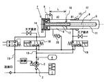
図1は本発明の液圧式押付装置の一実施例の液圧回路構成を示す説明図である。図に示す通り、Ps(=300kPa)に作動油が加圧されたリザーバタンク1は逆止弁2を介して給液ポンプとしての超磁歪ポンプ3に連通される。超磁歪ポンプ3は作動油を加圧しての作動圧油として蓄圧手段であるアキュムレータ4を配した高圧管路13内に供給する。今、高圧管路13内の作動圧油の圧力がP(=4MPa=4000kPa)に加圧されているとする。
FIG. 1 is an explanatory view showing a hydraulic circuit configuration of an embodiment of the hydraulic pressing device according to the present invention. As shown in the figure, the reservoir tank 1 in which the hydraulic oil is pressurized to Ps (= 300 kPa) is communicated with a giant magnetostrictive pump 3 as a feed pump via a
一方、ピストン5とシリンダ6とからなる押付手段7は、ピストン5が伸長する際に高圧管路に連通される小径室8及び大径室9と、ピストン5が減縮する際と減縮待機位置にある場合に連通される差圧室10とを備える。具体的には、ピストン5の略中央部に挿通孔11とシリンダ6にこの挿通孔11に挿通される挿通片12とを備え、挿通片12を介して挿通孔11内部と高圧管路13又は戻り管路15とを連通する管路14を備え、挿通片12に沿ってピストン5が摺動し、予め定められた長さLになった際に、ピストン5の挿通孔11とピストン5の後端側部屋とを連絡するブリード穴16を挿通片12に備える。
On the other hand, the pressing means 7 composed of the
即ち、挿通孔11と挿通片12とで構成される部屋が小径室8となり、ピストン5の後端側部屋が大径室9となり、ブリード穴16による小径室8と大径室9との連通動作が切換え手段となる。また、シリンダ6内壁とシリンダ6先端部のパッキン17とピストン5の側壁とで囲まれた部屋が差圧室10となる。
That is, the chamber constituted by the
図1はピストン5が減縮して減縮待機位置に摺動する場合の2つの切換え電磁弁18,19の切換え位置を示している。即ち、高圧管路13は差圧室10に連通され、小径室8及び大径室9は管路14から戻り管路15に連通している。小径室の面積をA1、大径室の面積をA2、差圧室の面積B1とすると、B1×P>A2×Psとなり、ピストン5は縮む。尚、戻り経路15中に絞り等を入れておけば急激なピストン5の減縮にブレーキがかけられる。
FIG. 1 shows the switching positions of the two switching
切換え電磁弁18,19の各ソレノイドに通電し、切換え弁を切り替えると差圧室10は戻り管路15に連通しリザーバタンク圧Psとなる。また、アキュムレータ4に蓄圧されていた油圧(P=4MPa=4000kPa)を保持する高圧管路13は小径室8に連通される。この時、P×A1>Ps×B1より、ピストン5は伸長する。この場合は、小径室8の面積A1が小さいため、高速で伸長する。尚、この動作時には、大径室9内部は負圧になるが、チェック弁20を介して戻り管路15に連通させてリザーバタンク圧Ps利用して負圧を防止する。
When the solenoids of the switching
小径部8のブリード穴16が空くまでピストン5がストローク(L)すると、ポンプ吐出圧がピストン面積全面の大径室9に作用し始める。この時の押付力はP×A2と高荷重の出力となり、所定の押付力が得られる。即ち、ブリード穴16が閉じている間は高速・低出力であるが、ブリード穴16が開くと低速・高出力に特性が切り換わる。
When the
以上のように、本実施例では、差圧室10を設けアキュムレータ4に圧力をためると同時に差圧室10にアキュムレータ4の圧力を作用させピストンを待機させているため、従来はバネを対向させ荷重によりピストンを待機させていたが、ピストンが伸長方向に進むときバネ荷重が負荷荷重として嵩上げされてしまう能力ロスが低減され、実質的にパッキン揺動抵抗と経路抵抗のみとなる。 As described above, in this embodiment, the differential pressure chamber 10 is provided to accumulate pressure on the accumulator 4, and simultaneously the pressure of the accumulator 4 is applied to the differential pressure chamber 10 to wait for the piston. Although the piston was made to wait by the load, the loss of ability of the spring load to be raised as the load load when the piston proceeds in the extending direction is reduced, and only the packing swing resistance and the path resistance are substantially provided.
また、アキュムレータ4を使用して圧力を保持することにより、通電されたコイルの磁界による超磁歪素子の伸縮によりポンプ作用を行っているため長時間運転することは期待できない超磁歪ポンプについても、圧力センサーと併用して蓄圧器(アキュムレータ、ACC)を使用することにより、より長時間の使用が可能となる。 In addition, the pressure is maintained by using the accumulator 4, and the pump action is performed by the expansion and contraction of the giant magnetostrictive element by the magnetic field of the energized coil. By using a pressure accumulator (accumulator, ACC) in combination with a sensor, it can be used for a longer time.
更に、ロッド作動時には小径室8を使用し、押付ける目的となる筐体に作用する場合には大径室9を使用することにより、微小流量しか発生しない超磁歪ポンプの利用範囲を大幅に広げることができる。また、通電する電源周波数により、吐出量が決定し低周波数の場合吐出量は少ないが大推力を発生することができることを利用して、ピストンを作動させる時には比較的推力を必要とせず大流量が出せるように高周波数を作用させ、磁歪ポンプの吐出能力を最大限発揮させることも可能である。逆に、推力を作用させるときには磁歪ポンプの推力を出させる低周波数によりポンプを運転させ、更に油圧力を小径室から大径室に連通させて大推力を発生させることも可能である。 Further, by using the small-diameter chamber 8 when the rod is operated and using the large-diameter chamber 9 when acting on the casing to be pressed, the range of use of the giant magnetostrictive pump that generates only a minute flow rate is greatly expanded. be able to. Also, by utilizing the fact that the discharge amount is determined by the power supply frequency to be energized and the discharge amount is small but a large thrust can be generated when the frequency is low, a large flow rate can be obtained without relatively requiring a thrust when operating the piston. It is also possible to exert a high frequency so that it can be discharged and to maximize the discharge capacity of the magnetostrictive pump. Conversely, when thrust is applied, it is possible to operate the pump at a low frequency that generates the thrust of the magnetostrictive pump, and to generate a large thrust by communicating the oil pressure from the small diameter chamber to the large diameter chamber.
1…リザーバタンク、
2…逆止弁、
3…超磁歪ポンプ、
4…アキュムレータ、
5…ピストン、
6…シリンダ、
7…押付手段、
8…小径室、
9…大径室、
10…差圧室、
11…挿通孔、
12…挿通片、
13…高圧管路、
14…管路、
15…戻り管路、
16…ブリード穴、
17…パッキン、
18…切換え電磁弁、
19…切換え電磁弁、
20…チェック弁、
1 ... reservoir tank,
2 ... Check valve,
3 ... Giant magnetostrictive pump,
4 ... Accumulator,
5 ... Piston,
6 ... cylinder,
7 ... Pressing means,
8 ... Small diameter chamber,
9 ... Large diameter chamber,
10 ... differential pressure chamber,
11 ... insertion hole,
12 ... Insertion piece,
13 ... High-pressure line,
14 ... pipeline,
15 ... return line,
16: Bleed hole,
17 ... Packing,
18 ... Switching solenoid valve,
19 ... Switching solenoid valve,
20 ... Check valve,
Claims (3)
前記給液ポンプからの作動圧液を蓄圧する蓄圧手段を管路内に備え、
前記押付手段は、前記ピストンが減縮待機位置から第1伸長位置に摺動する際に前記管路に連通される小径室と、前記ピストンが第1伸長位置から最大伸長位置に摺動する際に前記管路に連通される大径室と、前記小径室から大径室への連通路を切換える切換え手段とを備えたことを特徴とする液圧式押付装置。 In a hydraulic pressing device provided with a liquid supply pump that pressurizes and supplies hydraulic fluid from a reservoir tank to a pressing means composed of a piston and a cylinder via a pipe line,
A pressure accumulating means for accumulating the working pressure liquid from the liquid feed pump is provided in the pipe line,
The pressing means includes a small-diameter chamber communicated with the pipe line when the piston slides from the reduction standby position to the first extension position, and when the piston slides from the first extension position to the maximum extension position. A hydraulic pressing device, comprising: a large-diameter chamber communicated with the pipe line; and switching means for switching a communication path from the small-diameter chamber to the large-diameter chamber.
The hydraulic pressing device according to claim 1, wherein the liquid supply pump is a giant magnetostrictive pump.
Priority Applications (1)
| Application Number | Priority Date | Filing Date | Title |
|---|---|---|---|
| JP2004117842A JP2005299818A (en) | 2004-04-13 | 2004-04-13 | Hydraulic pressing device |
Applications Claiming Priority (1)
| Application Number | Priority Date | Filing Date | Title |
|---|---|---|---|
| JP2004117842A JP2005299818A (en) | 2004-04-13 | 2004-04-13 | Hydraulic pressing device |
Publications (1)
| Publication Number | Publication Date |
|---|---|
| JP2005299818A true JP2005299818A (en) | 2005-10-27 |
Family
ID=35331591
Family Applications (1)
| Application Number | Title | Priority Date | Filing Date |
|---|---|---|---|
| JP2004117842A Pending JP2005299818A (en) | 2004-04-13 | 2004-04-13 | Hydraulic pressing device |
Country Status (1)
| Country | Link |
|---|---|
| JP (1) | JP2005299818A (en) |
Cited By (2)
| Publication number | Priority date | Publication date | Assignee | Title |
|---|---|---|---|---|
| US8297924B2 (en) | 2007-06-11 | 2012-10-30 | Mitsubishi Heavy Industries, Ltd. | Actuation system, helicopter using the same, and controlling method therefor |
| CN111396527A (en) * | 2020-03-31 | 2020-07-10 | 潍坊新力蒙水产技术有限公司 | Liquid pressure transmission device |
-
2004
- 2004-04-13 JP JP2004117842A patent/JP2005299818A/en active Pending
Cited By (2)
| Publication number | Priority date | Publication date | Assignee | Title |
|---|---|---|---|---|
| US8297924B2 (en) | 2007-06-11 | 2012-10-30 | Mitsubishi Heavy Industries, Ltd. | Actuation system, helicopter using the same, and controlling method therefor |
| CN111396527A (en) * | 2020-03-31 | 2020-07-10 | 潍坊新力蒙水产技术有限公司 | Liquid pressure transmission device |
Similar Documents
| Publication | Publication Date | Title |
|---|---|---|
| KR102218113B1 (en) | Reversible hydraulic pressure converter with tubular valves | |
| KR910012555A (en) | Electro-hydraulic valve actuator | |
| MY153675A (en) | Variable valve actuator with a pneumatic booster | |
| DE602007005469D1 (en) | Actuation system for a servo-controlled mechanical transmission with oil leak recovery | |
| CN117098921A (en) | fluid circuit | |
| JP5819979B2 (en) | Storage module for hydraulic storage energy spring mechanism | |
| RU2679516C1 (en) | Double-acting hydraulic pressure amplifier | |
| JP2014532843A (en) | Hydraulic pressure booster cylinder | |
| JP6164528B2 (en) | Hydraulic drive device | |
| JP2005299818A (en) | Hydraulic pressing device | |
| CN112105848B (en) | Actuator and control and lubricant supply system for a motor vehicle | |
| CN117580737A (en) | aircraft braking system | |
| JP2007126974A (en) | Electromagnetic pump | |
| JP2002174201A (en) | Clamping device and booster cylinder used therefor | |
| JP7650611B2 (en) | Fluid Circuit | |
| JPWO2019049434A1 (en) | Fluid circuit for air cylinder | |
| JP3874608B2 (en) | Booster cylinder device | |
| KR102858701B1 (en) | Lubrication pump unit | |
| CN111852964B (en) | Hydraulic actuator arrangement | |
| EP2796727B1 (en) | Dew condensation preventing valve | |
| CN207687219U (en) | Start and stop for automatic transmission pump | |
| JP2001027175A (en) | Electrically-driven pump | |
| JP6077342B2 (en) | Fluid pressure control device | |
| JP2001012402A (en) | Hydraulic pressure control device | |
| JPH0222188Y2 (en) |
Legal Events
| Date | Code | Title | Description |
|---|---|---|---|
| A621 | Written request for application examination |
Free format text: JAPANESE INTERMEDIATE CODE: A621 Effective date: 20070220 |
|
| A977 | Report on retrieval |
Free format text: JAPANESE INTERMEDIATE CODE: A971007 Effective date: 20090105 |
|
| A131 | Notification of reasons for refusal |
Free format text: JAPANESE INTERMEDIATE CODE: A131 Effective date: 20090408 |
|
| A02 | Decision of refusal |
Free format text: JAPANESE INTERMEDIATE CODE: A02 Effective date: 20090805 |