JP2005299816A - Locking nut - Google Patents
Locking nut Download PDFInfo
- Publication number
- JP2005299816A JP2005299816A JP2004117807A JP2004117807A JP2005299816A JP 2005299816 A JP2005299816 A JP 2005299816A JP 2004117807 A JP2004117807 A JP 2004117807A JP 2004117807 A JP2004117807 A JP 2004117807A JP 2005299816 A JP2005299816 A JP 2005299816A
- Authority
- JP
- Japan
- Prior art keywords
- nut
- bolt
- head
- locking nut
- flange portion
- Prior art date
- Legal status (The legal status is an assumption and is not a legal conclusion. Google has not performed a legal analysis and makes no representation as to the accuracy of the status listed.)
- Granted
Links
Images
Landscapes
- Bolts, Nuts, And Washers (AREA)
Abstract
【目的】 ナットに偏心的な荷重がかからないようにしてボルトに曲げ荷重を作用させることが出来、しかも、冷間圧造加工が可能で、強力にゆるみ止め効果を発揮する。
【構成】 頭部1と、該頭部に一体に形成され、頭部より大径をなすフランジ部2を備えたゆるみ止めナットにおいて、フランジ部に凹部3を形成し、該フランジ部の底面2aを、一縁部Aからこれに対向する他縁部Bに向けてテーパー状に形成し、凹部底面3aを、頭部の上面5に対し平行面をなすように形成する。
【選択図】 図1[Purpose] It is possible to apply a bending load to the bolt so that an eccentric load is not applied to the nut, and it is possible to perform cold heading and exerts a strong anti-loosening effect.
[Structure] In a locking nut having a head portion 1 and a flange portion 2 formed integrally with the head portion and having a diameter larger than that of the head portion, a concave portion 3 is formed in the flange portion, and a bottom surface 2a of the flange portion Are formed in a tapered shape from one edge A toward the other edge B opposite to this, and the concave bottom surface 3a is formed so as to be parallel to the top surface 5 of the head.
[Selection] Figure 1
Description
本発明はゆるみ止めナットに係わり、特に、ボルト部材に挿通した被取付物をナット締めによって固定取り付けした際、振動や繰り返し荷重によって、ゆるみが可及的に発生しにくくしたゆるみ止めナットに関する。 The present invention relates to a locking nut, and more particularly to a locking nut in which loosening is less likely to occur due to vibration or repeated load when an object to be attached inserted through a bolt member is fixed by nut tightening.
ナットは被取付物に挿通されたボルトにネジ結合して被取付物間を締結する。かかるボルトとナットで締結された被取付物に振動や繰り返し荷重がかかるとゆるみが発生する。このため、従来技術としてゆるみが発生しないように工夫したゆるみ止めナットが種々提案されている(たとえば、特許文献1の図1〜図3および段落0021〜0024参照)。
この従来技術のゆるみ止めナットは、ナット本体に設けたフランジ部の径方向一方側に肉厚が薄く形成された弾性変形部を設け、他方側に剛性部を設けておき、ナット本体をボルトとネジ結合させたときに生じる締付け荷重により弾性変形部を弾性変形させてナットを傾斜し、ボルトを弾性変形部側に傾斜させる。すなわち、従来技術のゆるみ止めナットは、ナットの傾斜によって、ボルトがねじ穴から横方向の曲げ荷重を受けて弾性変形部側に弾性域内で曲がるようにして、ナットの雌ねじ部とボルトの雄ネジ部とを強く密着させると共に剛性部側締め付け面にボルトの曲げ荷重を付加させて、ナットとボルトとの緩み止め効果を向上させる。
In this prior art locking nut, an elastically deformable portion having a thin thickness is provided on one radial side of a flange portion provided on the nut body, a rigid portion is provided on the other side, and the nut body is a bolt. The elastic deformation portion is elastically deformed by a tightening load generated when the screws are coupled, and the nut is inclined, and the bolt is inclined toward the elastic deformation portion. That is, in the prior art locking nut, the bolt is subjected to a lateral bending load from the screw hole by the inclination of the nut so that it bends in the elastic region toward the elastic deformation portion, and the internal thread portion of the nut and the external thread of the bolt. The bolts are tightly adhered to each other and a bending load of the bolt is added to the rigid portion side tightening surface to improve the effect of preventing the nut and bolt from loosening.
従来技術のゆるみ止めナットは、ボルトに曲げを発生させることによりナットの雌ねじ部とボルトの雄ねじ部とを強く密着させることができ、このため強力にナットとボルトのゆるみ止め効果を発揮させることができる。しかし、一方で、ボルトに曲げを生じさせたナットの弾性変形部分が支持力を十分に発揮せず、ナットに偏心的な荷重がかかった状態になる、という問題があった。
また、一般にナットの加工方法においては、加工コスト、品質の面から、冷間圧造加工が有利であり、市場の主流となっている。しかし、従来技術のゆるみ止めナットでは、ナットに薄肉の弾性変形部と肉厚の剛性部とを形成する必要があるため、難加工形状となって圧造加工が出来ない。もしくは出来たとしても非常に高品位の加工技術が要求される。このため、切削加工でこのナットを形成すると、加工時間がかかり、切り粉の発生による材料のロスが生じるのはもちろん、バリの残留、組織が切断されることによる強度(特にねじ強度)の低下、といった問題が生じ、ナットとしての品質或いは経済性が一般の圧造ナットを下回ってしまう。
以上から本発明の目的は、ナットに偏心的な荷重がかからないようにしてボルトに曲げ荷重を作用させることが出来、しかも、冷間圧造加工が可能で、従来技術のゆるみ止めナットより一層強力にゆるみ止め効果を発揮することができるゆるみ止めナットを提供することである。
Prior art locking nuts can cause the bolt's internal threaded part and the bolt's male threaded part to be in close contact with each other by generating a bend in the bolt. it can. However, on the other hand, there is a problem that the elastically deformed portion of the nut that causes the bolt to bend does not sufficiently exert the supporting force, and an eccentric load is applied to the nut.
In general, in the nut processing method, cold forging is advantageous from the viewpoint of processing cost and quality, and it has become the mainstream of the market. However, in the conventional locking nut, since it is necessary to form a thin elastic deformation portion and a thick rigid portion on the nut, it is difficult to form and cannot be forged. Or, even if it can be done, very high quality processing technology is required. For this reason, if this nut is formed by cutting, it takes time to process, loss of material due to the generation of chips, as well as residual burrs and reduced strength (especially screw strength) due to the structure being cut. As a result, the quality or economy of the nut is lower than that of a general forged nut.
From the above, the object of the present invention is to apply a bending load to the bolt so that an eccentric load is not applied to the nut, and it is possible to perform cold heading, which is more powerful than the conventional locking nut. To provide a locking nut capable of exhibiting a locking effect.
上記課題は本発明によれば、頭部と、該頭部に一体に形成され、頭部より大径をなすフランジ部を備えたゆるみ止めナットにおいて、フランジ部に凹部を形成し、該フランジ部の底面を、一縁部からこれに対向する他縁部に向けてテーパー状に形成し、前記凹部底面を、頭部の上面に対し平行面をなすように形成してなるゆるみ止めナットにより達成される。 According to the present invention, there is provided a locking nut including a head and a flange formed integrally with the head and having a diameter larger than that of the head. The bottom surface of the taper is tapered from one edge toward the other edge opposite to this, and the bottom surface of the recess is achieved by a locking nut formed so as to be parallel to the top surface of the head. Is done.
本発明のゆるみ止めナットによれば、ボルトを介してナットを締付たときに、ワッシャー又は被取付物に当接されるフランジ部の底面がテーパー形状となっていることによって、ボルトに曲げ方向の力が生じ、ボルトの雄ネジがナットの雌ネジに強く密着する。しかも、フランジ部の底面に凹部を形成し、該凹部の底面がナット頭部の上面と平行面をなすように形成することによって、従来技術のように薄肉部と厚肉部が形成されることなく、雌ネジ部を挟んで左右に位置する切断面の断面積がどこをとっても略同じにできる。このため、ボルトに曲げが生じたとき、ナットに局部的な応力が生じて部分的に弾性変形することがなく、ナット全体でボルトの曲げによる押し付け力を受ける形で、効果的にネジ部のゆるみ止め効果を発揮することができる。
また、本発明のゆるみ止めナットによれば、弾性変形可能な薄肉部と剛肉部を設定する必要がなく、雌ネジ部を挟んで左右に位置する切断面の断面積がどこをとっても略同じとなる形状になるため、圧造加工による成形が可能である。なお、圧造加工によれば、高歩留まり、加工性、量産性、品質、経済性を向上することができる。
According to the locking nut of the present invention, when the nut is tightened via the bolt, the bottom surface of the flange portion that comes into contact with the washer or the attached object is tapered, so that the bending direction of the bolt As a result, the male screw of the bolt is firmly attached to the female screw of the nut. In addition, by forming a recess in the bottom surface of the flange portion and forming the bottom surface of the recess in parallel with the top surface of the nut head, a thin wall portion and a thick wall portion are formed as in the prior art. In other words, the cross-sectional areas of the cut surfaces located on the left and right sides of the female screw portion can be made substantially the same regardless of the cross-sectional area. For this reason, when the bolt is bent, local stress is generated in the nut and the elastic deformation of the nut is not caused. The anti-loosening effect can be demonstrated.
Further, according to the locking nut of the present invention, it is not necessary to set a thin-walled portion and a rigid-walled portion that can be elastically deformed, and the cross-sectional areas of the cut surfaces located on the left and right sides of the female screw portion are substantially the same regardless of where they are Therefore, it is possible to form by forging. In addition, according to forging processing, a high yield, workability, mass productivity, quality, and economical efficiency can be improved.
また、圧造加工を行うことによって、金属の組織が切断されることなく、高強度が確保され、弾性限界も上がるため、上記のナットを部分的に変形させることなくボルトに曲げを発生させ、その曲げをナット全体で受けて、ボルト雄ネジとナット雌ネジの密着を図る挙動をより一層的確に実現させることが可能となり、これにより一層効果的なゆるみ止め効果を発揮することが出来る。すなわち、圧造品は金属組織が均一になるため、応力伝達が良く、ボルトの曲げによって生じる力を局所から全体的に分散させることが出来るため、効果的なゆるみ止め効果を発揮することが出来る。 Also, by performing the forging process, the metal structure is not cut, high strength is ensured, and the elastic limit is increased, so that the bolt is bent without partially deforming the nut, It is possible to more accurately realize the behavior of receiving the bending of the entire nut and tightly adhering the bolt male screw and the nut female screw, thereby exhibiting a more effective loosening prevention effect. That is, since the metal structure of the forged product is uniform, the stress transmission is good, and the force generated by the bending of the bolt can be dispersed as a whole from the local area, so that an effective loosening prevention effect can be exhibited.
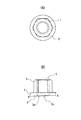
図1は本発明のゆるみ止めナットの実施形態説明図で、(A)は平面図、(B)は正面図である。本発明のゆるみ止めナットは、頭部(六角頭の部分)1と、該頭部に一体に形成され、頭部より大径をなすフランジ部2を備えている。フランジ部2には凹部3が形成され、該フランジ部2の底面2aを、一縁部Aからこれに対向する他縁部Bに向けてテーパー状に形成し、凹部3の底面3aを、頭部の上面5に対し平行面をなすように形成している。このゆるみ止めナットによれば、ボルトを介してナットを締付たとき、被取付物に当接されるフランジ部の底面がテーパー形状となっていることによって、ボルトに曲げ方向の力が生じてボルトの雄ネジがナットの雌ネジに強く密着し、しかも、ボルトに曲げが生じたとき、ナットに局部的な応力が生じて部分的に弾性変形することがなく、ナット全体でボルトの曲げによる押し付け力を受ける形で、効果的にネジ部のゆるみ止め効果を発揮することができる。
FIG. 1 is an explanatory view of an embodiment of a locking nut according to the present invention, in which (A) is a plan view and (B) is a front view. The locking nut of the present invention includes a head (hexagonal head) 1 and a
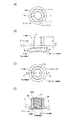
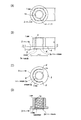
図2は本発明のゆるみ止めナットの第1実施例で、(A)は平面図、(B)は正面図、(C)は底面図、(D)は断面図であり、実際の寸法が付されているが、本発明はかかるサイズに限定するものではない。
本発明のゆるみ止めナットは、フランジ付き六角ナットとしての外形を有し、頭部1と、頭部より大径をなすフランジ部2を備えている。頭部1とフランジ部2は一体をなす形で冷間圧造加工により成形されている。頭部1は六角柱形状を備え、ボルトの雄ネジと嵌合するM12-P1.75の雌ネジ1aが(D)の断面図に示すようにフランジ部2の凹部3まで貫通して形成されている。なお、頭部1における六角形の対向辺間隔は17mm、高さは12mmである。
2A and 2B show a first embodiment of the locking nut according to the present invention, in which FIG. 2A is a plan view, FIG. 2B is a front view, FIG. 2C is a bottom view, and FIG. Although attached, the present invention is not limited to such a size.
The loosening prevention nut of this invention has the external shape as a hexagon nut with a flange, and is provided with the
フランジ部2の底面2aの中央には凹部3が形成されている。フランジ部2の底面2aは、一縁部Aからこれに対向する他縁部Bに向けてテーパー状に形成され、また、凹部3の底面3aは、頭部1の上面5に対し平行面をなすように形成されている。フランジ部2の一縁部Aにおける厚さは2.5mm、他縁部Bにおける厚さは3.5mmであり、1mmのテーパーが形成されている。凹部3は(C)に示すように円形に形成され、一縁部Cからこれに対向する他縁部Dに向けて深さが0から略1mmに変化するようになっている。
また、凹部3の底面3aを頭部1の上面5に対し平行面をなすように形成したことにより、(D)に示すように雌ネジ部1aの左右のフランジ部における厚みt1、t2は略同じ寸法となり、雌ネジ部1aを挟んで左右に位置する切断面SA、SBの断面積、即ち、(C)におけるa−a切断面とb−b切断面の各断面積は略同じになっている。
A
Further, since the
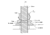
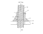
図3〜図5は第1実施例のゆるみ止めナット締付時におけるボルト・ナット挙動説明図であり、図2と同一部分には同一符号を付している。
図3に示すように、被取付物13とワッシャー14に挿通されたボルト12にナット11を嵌め込んで矢印方向に廻すと、図4に示すように、フランジ部2の一端がワッシャー14に接触し、他端がワッシャーに接触せず浮いた状態になる。図4の状態から更にナット11を回転して締め付けると、図5に示すようにボルト12には、締め付け前の本来の軸心CT1が、フランジ部2の底面2aのテーパー角度と直角をなす角度CT2となる形で、曲げが生じる。この曲げによる力は、ボルト12からナット11に締付力Fとして作用する。なお、本ナットは圧造加工により一体に加工しているため局所的に弱い部分がない、このため、ナット締付のためにかけたトルクは、ナット全体で受ける形となって、ナット11を変形させることはなく、ボルト12のみに曲げが発生する。
以上により、ナット11はボルト12に対して、強く締め付けられ、効果的なゆるみ止め効果を発揮する。即ち、ナット11にゆるみが生じようとしたとき、ボルト12に曲げが生じていることによって、ボルトの雄ネジ12aとナットの雌ネジ1aは常時締結力Fが介在する形で、結合しており、これによってゆるみが可及的に防止される。
3 to 5 are explanatory views of bolt / nut behavior when the locking nut of the first embodiment is tightened, and the same parts as those in FIG.
As shown in FIG. 3, when the
As described above, the
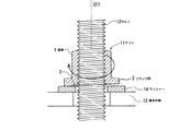
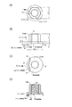
図6は本発明のゆるみ止めナットの第2実施例で、(A)は平面図、(B)は正面図、(C)は底面図、(D)は断面図であり、図2の第1実施例と同一部分には同一符号を付している。第1実施例と異なる点は、フランジ部2の底面形状であり、(B),(C)に示すようにフランジ部2の底面2aが一縁部A′A′からこれに対向する他縁部Bに向けてテーパー状に形成され、AA′円周部分は第1実施例と異なり、凹部底面3aと同一平面を形成するようになっている。すなわち、AA′円周部分は凹部底面3aを構成するようになっている。
第2実施例のゆるみ止めナットの締付時における作用は第1実施例と同様であり、ボルトを介してナットを締付たときに、被取付物に当接されるフランジ部の底面2aがテーパー形状となっていることによって、ボルトに曲げ方向の力が生じ、ボルトの雄ネジがナットの雌ネジに強く密着し、しかも、ボルトに曲げが生じたとき、ナットに局部的な応力が生じて部分的に弾性変形することがなく、ナット全体でボルトの曲げによる押し付け力を受ける形で、効果的にネジ部のゆるみ止め効果を発揮することができる。
6A and 6B show a second embodiment of the locking nut of the present invention, in which FIG. 6A is a plan view, FIG. 6B is a front view, FIG. 6C is a bottom view, and FIG. The same parts as those in the first embodiment are denoted by the same reference numerals. The difference from the first embodiment is the shape of the bottom surface of the
The operation at the time of tightening the locking nut of the second embodiment is the same as that of the first embodiment. When the nut is tightened via a bolt, the
図7は本発明のゆるみ止めナットの第3実施例で、(A)は平面図、(B)は正面図、(C)は底面図、(D)は断面図であり、図2の第1実施例と同一部分には同一符号を付している。第1実施例と異なる点は、フランジ部2の底面形状であり、(B),(C)に示すようにフランジ部2の底面2aが略900の範囲で円弧状に設けられ、一縁部B′B′からこれに対向する他縁部Bに向けてテーパー状に形成され、また、AB′円周部分は第1実施例と異なり、凹部底面3aと同一平面を形成するようになっている。すなわち、AB′円周部分は凹部底面3aを構成するようになっており、テーパー面BB′を延長すると縁部Aを含むようにテーパーが形成されている。
第3実施例のゆるみ止めナットの締付時における作用は第1実施例と同様であり、ボルトを介してナットを締付たときに、被取付物に当接されるフランジ部の底面がテーパー形状となっていることによって、ボルトに曲げ方向の力が生じ、ボルトの雄ネジがナットの雌ネジに強く密着し、しかも、ボルトに曲げが生じたとき、ナットに局部的な応力が生じて部分的に弾性変形することがなく、ナット全体でボルトの曲げによる押し付け力を受ける形で、効果的にネジ部のゆるみ止め効果を発揮することができる。
7A and 7B show a third embodiment of the locking nut of the present invention, in which FIG. 7A is a plan view, FIG. 7B is a front view, FIG. 7C is a bottom view, and FIG. The same parts as those in the first embodiment are denoted by the same reference numerals. Differs from the first embodiment, a bottom shape of the
The operation at the time of tightening the locking nut of the third embodiment is the same as that of the first embodiment, and when the nut is tightened via the bolt, the bottom surface of the flange portion that comes into contact with the attached object is tapered. Due to the shape, a force in the bending direction is generated on the bolt, and the male screw of the bolt closely adheres to the female screw of the nut, and when the bolt is bent, local stress is generated on the nut. It is not elastically deformed partially, and the effect of preventing the loosening of the threaded portion can be effectively exhibited by receiving the pressing force due to the bending of the bolt in the whole nut.
以上、本発明によれば、フランジ部に凹部を形成し、該フランジ部の底面を、一縁部からこれに対向する他縁部に向けてテーパー状に形成し、前記凹部底面を、頭部の上面に対し平行面をなすように形成したからナットに偏心的な荷重がかからないようにしてボルトに曲げ荷重を作用させることが出来、しかも、冷間圧造加工が可能で、一層強力にゆるみ止め効果を発揮することができる As described above, according to the present invention, the concave portion is formed in the flange portion, the bottom surface of the flange portion is formed in a tapered shape from one edge portion to the other edge portion facing the flange portion, and the concave bottom surface is formed on the head portion. Since it is formed so as to be parallel to the upper surface of the nut, it is possible to apply a bending load to the bolt so that an eccentric load is not applied to the nut. Can be effective
1 頭部(六角頭の部分)
2 フランジ部
2a フランジ部の底面
3 凹部
3a 凹部の底面
5 頭部の上面
1 head (hex head)
2
Claims (2)
フランジ部に凹部を形成し、
該フランジ部の底面を、一縁部からこれに対向する他縁部に向けてテーパー状に形成し、
前記凹部底面を、頭部の上面に対して平行面をなすように形成してなる、
ことを特徴とするゆるみ止めナット。 In the locking nut that is formed integrally with the head and the flange that has a larger diameter than the head,
Forming a recess in the flange,
The bottom surface of the flange portion is formed in a tapered shape from one edge portion toward the other edge portion facing the one edge portion,
The concave bottom surface is formed so as to be parallel to the top surface of the head.
A locking nut characterized by that.
Priority Applications (1)
| Application Number | Priority Date | Filing Date | Title |
|---|---|---|---|
| JP2004117807A JP4304113B2 (en) | 2004-04-13 | 2004-04-13 | Locking nut |
Applications Claiming Priority (1)
| Application Number | Priority Date | Filing Date | Title |
|---|---|---|---|
| JP2004117807A JP4304113B2 (en) | 2004-04-13 | 2004-04-13 | Locking nut |
Publications (2)
| Publication Number | Publication Date |
|---|---|
| JP2005299816A true JP2005299816A (en) | 2005-10-27 |
| JP4304113B2 JP4304113B2 (en) | 2009-07-29 |
Family
ID=35331589
Family Applications (1)
| Application Number | Title | Priority Date | Filing Date |
|---|---|---|---|
| JP2004117807A Expired - Fee Related JP4304113B2 (en) | 2004-04-13 | 2004-04-13 | Locking nut |
Country Status (1)
| Country | Link |
|---|---|
| JP (1) | JP4304113B2 (en) |
-
2004
- 2004-04-13 JP JP2004117807A patent/JP4304113B2/en not_active Expired - Fee Related
Also Published As
| Publication number | Publication date |
|---|---|
| JP4304113B2 (en) | 2009-07-29 |
Similar Documents
| Publication | Publication Date | Title |
|---|---|---|
| JP3491279B2 (en) | Caulking nut and manufacturing method thereof | |
| KR101230876B1 (en) | Fastener and fastening structure | |
| JP6437313B2 (en) | Locking special double nut | |
| JP2006057801A (en) | Tightening screw | |
| JP4340103B2 (en) | Screw fastening structure | |
| JP2009115297A (en) | Locking nut, manufacturing method thereof, and processing jig thereof | |
| JP2015203492A (en) | Lock nut | |
| JPH07151126A (en) | Nut | |
| JP4304113B2 (en) | Locking nut | |
| JP3051390B1 (en) | Fixing bolt and fixing method | |
| JP2006220210A (en) | Intervening member, fastener and fastened body | |
| JP2006118582A (en) | Female screw part | |
| JP3199619U (en) | Locking nut | |
| JP3100223U (en) | Nut-integrated plate-shaped parts | |
| JP2002139010A (en) | Screw with thin head | |
| JP4950911B2 (en) | Fastening member | |
| JP3739602B2 (en) | bolt | |
| JPH09250535A (en) | Washer, double nut structure and steady rest structure | |
| JP2003148438A (en) | Fastening device | |
| JP5677012B2 (en) | Fastening member | |
| KR102866762B1 (en) | Combination structure of rivet nut and rivet bolt | |
| JP2007187273A (en) | Washers, nuts, and fasteners | |
| JP2002242922A (en) | Washer, and screw fastener using the same washer | |
| JP2009084884A (en) | Tightening structure and building member connection structure | |
| JP2509446B2 (en) | How to fix screws to metal plate |
Legal Events
| Date | Code | Title | Description |
|---|---|---|---|
| A131 | Notification of reasons for refusal |
Free format text: JAPANESE INTERMEDIATE CODE: A131 Effective date: 20071023 |
|
| A521 | Written amendment |
Free format text: JAPANESE INTERMEDIATE CODE: A523 Effective date: 20071114 |
|
| A131 | Notification of reasons for refusal |
Free format text: JAPANESE INTERMEDIATE CODE: A131 Effective date: 20080430 |
|
| A521 | Written amendment |
Free format text: JAPANESE INTERMEDIATE CODE: A523 Effective date: 20080623 |
|
| TRDD | Decision of grant or rejection written | ||
| A01 | Written decision to grant a patent or to grant a registration (utility model) |
Free format text: JAPANESE INTERMEDIATE CODE: A01 Effective date: 20090421 |
|
| A01 | Written decision to grant a patent or to grant a registration (utility model) |
Free format text: JAPANESE INTERMEDIATE CODE: A01 |
|
| A61 | First payment of annual fees (during grant procedure) |
Free format text: JAPANESE INTERMEDIATE CODE: A61 Effective date: 20090427 |
|
| FPAY | Renewal fee payment (event date is renewal date of database) |
Free format text: PAYMENT UNTIL: 20120501 Year of fee payment: 3 |
|
| R150 | Certificate of patent or registration of utility model |
Free format text: JAPANESE INTERMEDIATE CODE: R150 |
|
| FPAY | Renewal fee payment (event date is renewal date of database) |
Free format text: PAYMENT UNTIL: 20120501 Year of fee payment: 3 |
|
| FPAY | Renewal fee payment (event date is renewal date of database) |
Free format text: PAYMENT UNTIL: 20130501 Year of fee payment: 4 |
|
| FPAY | Renewal fee payment (event date is renewal date of database) |
Free format text: PAYMENT UNTIL: 20140501 Year of fee payment: 5 |
|
| R250 | Receipt of annual fees |
Free format text: JAPANESE INTERMEDIATE CODE: R250 |
|
| R250 | Receipt of annual fees |
Free format text: JAPANESE INTERMEDIATE CODE: R250 |
|
| R250 | Receipt of annual fees |
Free format text: JAPANESE INTERMEDIATE CODE: R250 |
|
| LAPS | Cancellation because of no payment of annual fees |