JP2005299799A - Outside joint member of uniform velocity universal joint - Google Patents
Outside joint member of uniform velocity universal joint Download PDFInfo
- Publication number
- JP2005299799A JP2005299799A JP2004117084A JP2004117084A JP2005299799A JP 2005299799 A JP2005299799 A JP 2005299799A JP 2004117084 A JP2004117084 A JP 2004117084A JP 2004117084 A JP2004117084 A JP 2004117084A JP 2005299799 A JP2005299799 A JP 2005299799A
- Authority
- JP
- Japan
- Prior art keywords
- mouse
- velocity universal
- joint
- mouse member
- universal joint
- Prior art date
- Legal status (The legal status is an assumption and is not a legal conclusion. Google has not performed a legal analysis and makes no representation as to the accuracy of the status listed.)
- Withdrawn
Links
Images


Landscapes
- Diaphragms And Bellows (AREA)
Abstract
Description
この発明は等速自在継手の外側継手部材に関する。より詳しくは、内径部とトルク伝達要素と係合するトラック溝部とを円周方向に交互に配置したカップ状または筒状のマウス部分を板材または管材からプレスなどの冷間加工により成形した薄肉の外側継手部材に関する。 The present invention relates to an outer joint member of a constant velocity universal joint. More specifically, a cup-shaped or cylindrical mouse portion in which inner diameter portions and track groove portions that engage with torque transmitting elements are alternately arranged in the circumferential direction is formed by cold working such as pressing from a plate material or a tube material. The present invention relates to an outer joint member.
内径部とトルク伝達要素と係合するトラック溝部とを円周方向に交互に配置したカップ状または筒状のマウス部分を有する外側継手部材を製造するための従来の技術としては、一体素材として温間鍛造または熱間鍛造により成形を行う方法や、カップ状または筒状のマウス部材を板材または管材からプレスなどの冷間加工により成形し、別体として製作したステム部材と接合して外側継手部材を得る方法などがある。 As a conventional technique for manufacturing an outer joint member having a cup-shaped or cylindrical mouse portion in which an inner diameter portion and a track groove portion that engages with a torque transmission element are alternately arranged in the circumferential direction, as an integrated material, The outer joint member is formed by cold forging such as a method of forming by hot forging or hot forging, or a cup-shaped or cylindrical mouse member by cold working such as pressing from a plate material or tube material, and joining with a stem member manufactured separately. There are ways to get it.
近年、自動車業界においては、等速自在継手の小型・軽量化が要求されるようになってきている。後者の冷間加工により得られる外側継手部材はこのようなニーズに応えるものである。また、冷間加工では、工程削減、工具の長寿命化および合理化の点から全体としてコストダウンを図ることができる。これに対して前者の温間または熱間鍛造による成形方法では、鍛造型が熱により劣化することや、多品種にわたる製品形状に対して一品一様で鍛造型が必要になること、鍛造工程および前処理などが煩雑な多工程となること、などの理由から製造コストを低減できないという問題点がある。 In recent years, the automobile industry has been required to reduce the size and weight of constant velocity universal joints. The outer joint member obtained by the latter cold working meets such needs. In cold working, the cost can be reduced as a whole from the viewpoint of process reduction, tool life extension and rationalization. On the other hand, in the former forming method by warm or hot forging, the forging die is deteriorated by heat, a uniform forging die is required for various product shapes, the forging process and There is a problem in that the manufacturing cost cannot be reduced because the pretreatment and the like are complicated multi-steps.
従来の技術として、特開平9−76026号公報の図4には、マウス開口端部に外周側に湾曲する鍔状部分を有する形状が開示されている。特開2000−329152号公報には、マウス部材の開口端部に断面略円形状のフランジ部を形成することが開示されている。特開2000−24736号公報には、鍔状部分やフランジ部を設けず、開口端部に向かって同一断面形状に成形されたマウス部材が開示されている。
プレスなどの冷間加工においては、材料に大きな変形を与える部分において割れが生じやすいため、温間または熱間鍛造に比べて材料に加えることのできる変形量が小さい。結果として、プレスなどの冷間加工により得られるカップ状または筒状のマウス部材は、温間または熱間鍛造により得られる外側継手部材のカップ状マウス部分に比べ、その横断面において、薄肉であり、かつ、円周方向における肉厚の差が小さい略均一な肉厚の断面形状となる。 In cold working such as pressing, cracks are likely to occur in parts that give large deformations to the material, so the amount of deformation that can be applied to the material is small compared to warm or hot forging. As a result, the cup-shaped or cylindrical mouse member obtained by cold working such as pressing is thinner in cross section than the cup-shaped mouse part of the outer joint member obtained by warm or hot forging. In addition, the cross-sectional shape has a substantially uniform thickness with a small difference in thickness in the circumferential direction.
深絞りやしごきなどの加工方法により冷間加工されたマウス部材においては、特にその開口端部において、成形による歪が集中して、加工硬化による割れが発生しやすい。そのため、マウス部材の開口端部の形状によって、成形のしやすさは大きく左右される。 In a mouse member that has been cold worked by a working method such as deep drawing or ironing, distortion due to molding is concentrated particularly at the opening end portion, and cracks due to work hardening are likely to occur. Therefore, the ease of molding is greatly affected by the shape of the open end of the mouse member.
また、等速自在継手としてより大きなトルクを伝達するためには、内側継手部材からマウス部材に加わる荷重に対する破壊強度を高める必要がある。マウス部材を厚肉にすることで強度は高められるが、冷間加工における成形のしやすさは大きく低下する。 In order to transmit a larger torque as a constant velocity universal joint, it is necessary to increase the breaking strength against a load applied from the inner joint member to the mouse member. Although the strength can be increased by making the mouse member thick, the ease of forming in cold working is greatly reduced.
特開平9−76026号公報における鍔状部分または特開2000−329152号公報におけるフランジ部は、マウス内部の密閉を目的としたブーツを固定するために、ブーツの一端との係合形状として機能するが、継手としてのトルク伝達機能に直接関与する部分ではない。また、前者の鍔状部分は、マウス部材が厚肉になるほど湾曲部の曲率半径を小さく成形することが難しいことから、プレス工程で成形した大きな鍔部をその後の旋削工程で成形するなど、材料の歩留まりを低下させる原因となる。また、後者のフランジ部は、マウス開口端部に連接されているため、外側継手部材が軸方向に長くなり、コンパクトさが失われる。そのため、継手構造としてのコンパクト化、軽量化、材料削減の点から、より有利な形状が必要であった。 The flange portion in Japanese Patent Laid-Open No. 9-76026 or the flange portion in Japanese Patent Laid-Open No. 2000-329152 functions as an engagement shape with one end of the boot in order to fix the boot for the purpose of sealing the inside of the mouse. However, it is not a part directly related to the torque transmission function as a joint. In addition, since it is difficult to mold the curvature radius of the curved portion as the thickness of the mouse member becomes thicker, the former collar-shaped portion is made of a material such as molding a large collar formed in the pressing process in the subsequent turning process. Cause a decrease in yield. Moreover, since the latter flange part is connected with the mouse | mouth opening edge part, an outer joint member becomes long in an axial direction, and compactness is lost. Therefore, a more advantageous shape is required from the viewpoint of compactness, weight reduction, and material reduction as a joint structure.
また、特開2000−24736号公報に記載された従来の技術の場合、トラック溝部の開口端部外周面に設けた係合溝によりブーツの一端を固定する。また、隣接するトラック溝部の間に位置する小内径部分の開口端部内周部には、シャフトとの干渉を抑制するためのチャンファ部が設けてあるが、冷間加工により成形されるマウス部材は薄肉であるため、大きなチャンファ部を形成してシャフトとの干渉を十分に防ぐことができず、継手の可動範囲が制約される。また、チャンファ部が部分的に薄肉となるため、マウス部材の強度が低下するなどの問題があった。 In the case of the conventional technique described in Japanese Patent Laid-Open No. 2000-24736, one end of the boot is fixed by an engagement groove provided on the outer peripheral surface of the opening end of the track groove. In addition, a chamfer part for suppressing interference with the shaft is provided on the inner peripheral part of the opening end part of the small inner diameter part located between the adjacent track groove parts, but the mouse member formed by cold working is Since it is thin, a large chamfer portion cannot be formed to sufficiently prevent interference with the shaft, and the movable range of the joint is restricted. Further, since the chamfer part is partially thin, there is a problem that the strength of the mouse member is lowered.
本発明の目的は、プレスなどの冷間加工における成形性を低下させることなく、機能面において有利なマウス部材の開口端部形状を提供することにある。 An object of the present invention is to provide an opening end shape of a mouse member that is advantageous in terms of function without degrading formability in cold working such as pressing.
この発明の等速自在継手の外側継手部材は、冷間加工により成形した薄肉のマウス部材とステム部材とを接合してなる外側継手部材であって、前記マウス部材が、一端にて開口し、円周方向に複数配置された軸方向に延びるトラック溝部を有し、隣接するトラック溝部間に、開口端側に向かって拡径したテーパ部を設けたことを特徴とするものである。 The outer joint member of the constant velocity universal joint of the present invention is an outer joint member formed by joining a thin mouse member formed by cold working and a stem member, and the mouse member opens at one end, A plurality of circumferentially extending track groove portions extending in the axial direction are provided, and a taper portion whose diameter is increased toward the opening end side is provided between adjacent track groove portions.
前記テーパ部は、マウス部材の一部として冷間加工により一体成形することにより(請求項2)、除去加工などによりチャンファ部を設ける場合のように肉厚が減少することがないため、強度低下を防ぐことができる。また、テーパ部の大きさはマウス部材の肉厚に制約されず、シャフトとの干渉を十分に抑えることができる。 The tapered portion is integrally formed by cold working as a part of the mouse member (Claim 2), and the thickness does not decrease as in the case where the chamfer portion is provided by removal processing or the like. Can be prevented. Further, the size of the tapered portion is not limited by the thickness of the mouse member, and interference with the shaft can be sufficiently suppressed.
また、前記トラック溝部の外周面に、ブーツを固定するための円周方向に走る溝を形成することにより(請求項3)、この溝とテーパ部により、ブーツの一端をマウス部材に確実に固定することができ、高いシール性を得ることができる。トラック溝部の外周面の溝は、マウス部材を冷間加工により成形した後旋削などの除去加工により形成することができる。 Further, by forming a groove running in the circumferential direction for fixing the boot on the outer peripheral surface of the track groove portion (Claim 3), one end of the boot is securely fixed to the mouse member by the groove and the tapered portion. And high sealing performance can be obtained. The groove on the outer peripheral surface of the track groove portion can be formed by removal processing such as post-turning in which the mouse member is formed by cold working.
本発明によれば、冷間加工における成形性と、製造コスト削減、機能改善を図ることができ、軽量、コンパクト、低コストで優れた性能をもつ等速自在継手を提供することができる。 ADVANTAGE OF THE INVENTION According to this invention, the formability in cold work, manufacturing cost reduction, and functional improvement can be aimed at, and the constant velocity universal joint with the outstanding performance can be provided in light weight, a compact, low cost.
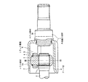
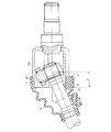
まず、図1に示すトリポード型等速自在継手に適用した場合を例にとって本発明の実施の形態を説明する。 First, the embodiment of the present invention will be described by taking as an example the case where it is applied to the tripod type constant velocity universal joint shown in FIG.
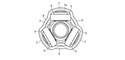
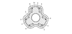
トリポード型等速自在継手は、駆動軸または従動軸と接続される外側継手部材1と、従動軸または駆動軸となるシャフト2と接続されるトリポード部材3とで構成される。外側継手部材1はここでは有底筒状またはカップ状で、内周の円周方向三等分位置に軸方向に延びるトラック溝部6を有する(図2、図3参照)。トリポード部材3は円周方向の三等分位置から半径方向に突出した三本の脚部を有する。各脚部にはニードルローラ4を介して回転自在にリング5が取り付けてある。外側継手部材1の内部にトリポード部材3を挿入し、リング5を外側継手部材1のトラック溝部6に転動自在に係合させることにより、外側継手部材1とトリポード部材3との間で回転トルクの伝達が可能となる。
The tripod type constant velocity universal joint includes an
外側継手部材1はマウス部材1aとステム部材1bとで構成される。マウス部材1aは板材より連続プレス加工によりカップ状に成形され、それとは別体として製作されたステム部材1bと一体的に接合されている。マウス部材1aの開口端部側で、トラック溝部6の外周面に、円周方向に走る溝7が形成してある。そして、隣接するトラック溝部6間にはテーパ部8が形成してある。
The outer
プレス加工により成形されるマウス部材1aは、前述した加工上の制約により、図2および図3に示すように、略均一な肉厚の横断面形状を有している。また、プレス加工においては炭素含有量の低い材料の方がより加工が容易であるため、浸炭焼入れ処理用の低炭素鋼が用いられることが多いが、高周波焼入れ処理用の高炭素鋼を用いてもよい。マウス部材1aは、プレス加工において、円盤状の素材から数工程の深絞り加工、しごき加工、打ち抜き加工などを経て、所要のカップ形状に成形される。さらに旋削などの成形加工の後に、浸炭焼入れにより全表面に硬化層を設けた後、ステム部材1bと接合される。
As shown in FIGS. 2 and 3, the mouse member 1a formed by press working has a substantially uniform cross-sectional shape as shown in FIGS. In press working, materials with lower carbon content are easier to process, so low carbon steel for carburizing and quenching is often used, but high carbon steel for induction hardening is used. Also good. The mouse member 1a is formed into a required cup shape through several steps of deep drawing, ironing, punching, and the like from a disk-shaped material in press working. Further, after a forming process such as turning, a hardened layer is provided on the entire surface by carburizing and quenching, and then joined to the
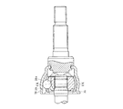
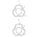
マウス部材1aとステム部材1bとの接合方法を例示するならば次のとおりである。図10に示すように、マウス部材1aは、薄肉の鋼板からなるパイプ素材または有底の円筒状素材をプレス加工して全体がカップ状に成形されている。マウス部材1aは、内周面に複数のトラック溝6が形成され、その結果、横断面は花冠状を呈している(図11参照)。マウス部材1aの底の中央には、プレスの打抜き加工によって孔40が設けてある。孔40の内周面には、図11(A)に示すような多角形面または図11(B)に示すようなセレーション溝が形成され、いずれの場合も浸炭焼入れや高周波焼入れ等の表面硬化処理が施してある。
An example of a method for joining the mouse member 1a and the
マウス部材1aと接合されるステム部材1bは、一方の端部の外周面にセレーション部が形成され、他方の端部に大径部1cが形成され、その大径部1cの先端にマウス部材1aの孔40に嵌合する突出部1dが形成されている。この突出部1dは生材のままであり、表面の硬化処理はされていない。また、その外径寸法は、孔40の内接円径よりも若干大きく設定してある。大径部1cと突出部1dとの間の段部に周溝1eが形成され、その周溝1eにOリングその他のシール部材42が装着される。
The
そして、図10(A)に示すように、マウス部材1aの孔40にステム部材1bの突出部1dを圧入した後、マウス部材1aの内側に突出した突出部1dの先端をかしめ工具46により軸方向に打撃する。そうすることにより、図10(B)に符号44で示すように突出部1dの端部をかしめてマウス部材1aとステム部材1bとを接合する。このようにして接合した状態では、孔40の内周面に設けた多角形面やセレーション溝が突出部1dに転写されてマウス部材1aとステム部材1bとの回り止めがなされ、また、軸方向にはカシメ部44によって嵌合部のガタが殺され、マウス部材1aとステム部材1bとは一体で回転する。ステム部材1bの突出部1dのかしめは、圧入によって生じるマウス部材1aの底の変形を矯正する効果もある。
Then, as shown in FIG. 10A, after the protruding
図12(A)(B)は、マウス部材1aとステム部材1bとの別の接合構造を示すものである。この場合のステム部材1bは、先端部のセレーション部も含め、マウス部材1aの孔40より若干小径に形成され、また、ステム部材1bの他端部には孔40の内径より若干大径の嵌合部1cが形成され、さらに、その先端に抜止め用のつば1fが形成してある。また、マウス部材1aの孔40には、前述の図11と同様の多角形面またはセレーション溝が形成され、かつ、表面硬化処理が施してある。このステム部材1bを図12(A)に矢印で示すようにマウス部材1aの内側から孔40に挿入し、嵌合部1cの部分では、図12(B)に示すように、ダイス50に嵌めるとともにかしめ工具46によりステム部材1bを打撃して符号48で示すようにかしめる。嵌合部1cには孔40の多角形面またはセレーション溝が転写される。
12A and 12B show another joint structure between the mouse member 1a and the
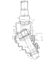
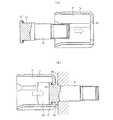
次に、図4に示すように、図1に示したトリポード型等速自在継手は継手内部の密閉を目的としたブーツ9を装着して使用する。ブーツ9は一方の開口端部をマウス部材1aの開口端部に装着し、他方の開口端部をシャフト2の外径部に装着し、それぞれ固定バンド13,14で締結する。ブーツ9は、外側継手部材1に対するシャフト2の角度変位θ、軸方向変位Xの変動を許容するため、大端側取付け部10,11と小端側取付け部12の間に蛇腹状の構造を有しており、屈曲耐久性に優れたゴム材料を用いて射出成形などにより製造される。マウス部材1aの開口端部外周面に係合する大端側取付け部10,11は、それぞれ円周方向溝7とテーパ部8の周囲に密着する内周形状に成形されている。
Next, as shown in FIG. 4, the tripod constant velocity universal joint shown in FIG. 1 is used with a
マウス部材1aの開口端部に形成されたテーパ部8は、図4に示すように、外側継手部材1に対するシャフト2の角度変位θが大きい場合に、シャフト2の外径とマウス部材1の開口端部との干渉を防ぐ機能を果たす。これにより、より大きな可動範囲が得られ、幅広い用途に適用できる等速自在継手とすることができる。
As shown in FIG. 4, when the angular displacement θ of the shaft 2 with respect to the outer
図5に比較例としてのマウス部材15aを備えたトリポード型等速自在継手を示す。このマウス部材15aは、開口端部にテーパ部を有さず、隣接するトラック溝部間の小内径部18の内周面に、プレス加工の後の旋削などの除去加工によりチャンファ16を設けてある。図示のとおり、チャンファ16の開口端側は薄肉となるため、マウス部材15aの強度低下の問題から、チャンファ16を大きくすることは難しい。その結果、テーパ部8を有するマウス部材1aに比べてシャフト2との干渉を十分に抑えることができない。
FIG. 5 shows a tripod constant velocity universal joint provided with a
また、マウス部材1aのテーパ部8はプレス加工工程において一体に成形されるが、テーパ部8を有しないマウス部材15aの開口端部形状に比べて、深絞り加工やしごき加工における開口端部のひずみ量を抑えることができ、その結果、割れが発生しにくく成形が容易となる。
Further, the
一方、マウス部材1a,15aの開口端部に対するブーツ9,19の係合に関して、円周方向溝7,17に対するブーツ大端側取付け部10,20の係合状態は同一であるが、マウス部材1aのテーパ部8に対するブーツ大端側取付け部11の係合状態は、マウス部材15aのストレート部18に対するブーツ大端側取付け部21の係合状態に比べて軸方向の固定保持力が強く、継手の使用状況において、マウス部材1aに対してブーツ大端側取付け部11が軸方向にずれにくい。そのため、テーパ部8を有するマウス部材1aとブーツ9の方が、より高いシール性を得ることができる。
On the other hand, regarding the engagement of the
図6に、トラック溝23部の外周面に円周方向溝(7:図1参照)を設けない構造のマウス部材22aを示す。前述のとおり、図1の実施の形態では、継手の使用状況においてブーツ9の大端側取付け部10がマウス部材1aに対して軸方向にずれにくい。これに対して図6のマウス部材22aは、円周方向溝が設けられていないためブーツ25の大端側取付け部26がマウス部材22aに対してずれやすく、シール性が劣る。とはいえ、開口端部に向かって大きく拡大するテーパ部24とブーツ大端側取付け部27とが係合しているため、これによりブーツ大端側取付け部26のずれが防止されるという効果が期待できる。一方、図6の実施の形態におけるマウス部材22aは、トラック溝23部の外周面に円周方向溝がないのでマウス部材の開口端部付近に薄肉の部分がなく、図1の実施の形態におけるマウス部材1aよりも高い強度が得られる。したがって、継手の使用条件に応じて、円周方向溝を有しないマウス部材22aの構造を採用することも可能である。
FIG. 6 shows a
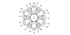
図7ないし図9に、バーフィールド型等速自在継手に適用した実施の形態を示す。図示するように、マウス部材28aの開口端部は、トラック溝部29とテーパ部31が円周方向で交互に現れる。ここでもテーパ部31は隣接するトラック溝部29間に位置し、マウス部材28aの開口端側に向かって拡径している。トラック溝部29の外周面には円周方向溝30が設けてある。この実施の形態は、前述のトリポード型等速自在継手の実施の形態と同様に、冷間加工により成形しやすく、マウス部材28aの強度低下を抑えて継手の可動範囲を確保し、ブーツ(図示省略)のシール性を良好に保つことができる。図8および図9は、マウス部材28aに6本のトラック溝部29を設けた場合を例示しているが、トラック溝部29の数は6本に限らず5本あるいは8本など任意でよい。また、継手の使用条件に応じて、図6の実施の形態と同様、トラック溝部29の外周面に円周方向溝30を設けない構造を採用することも可能である。
7 to 9 show an embodiment applied to a Barfield type constant velocity universal joint. As shown in the drawing, the
以上に本発明の実施例を解説したが、本発明の等速自在継手は上記した実施の形態に限定されるものではなく、本発明の主旨を逸脱しない範囲内において種々変更を加え得ることは勿論である。 Although the embodiments of the present invention have been described above, the constant velocity universal joint of the present invention is not limited to the above-described embodiments, and various modifications can be made without departing from the scope of the present invention. Of course.
1 外側継手部材
1a,15a,22a,28a マウス部材
1b ステム部材
2 シャフト
3 トリポード部材
4 ニードルローラ
5 リング
6,23,29 トラック溝部
7,17,30 円周方向溝
8,24,31 テーパ部
9,19,25 ブーツ
DESCRIPTION OF
Claims (3)
Priority Applications (1)
| Application Number | Priority Date | Filing Date | Title |
|---|---|---|---|
| JP2004117084A JP2005299799A (en) | 2004-04-12 | 2004-04-12 | Outside joint member of uniform velocity universal joint |
Applications Claiming Priority (1)
| Application Number | Priority Date | Filing Date | Title |
|---|---|---|---|
| JP2004117084A JP2005299799A (en) | 2004-04-12 | 2004-04-12 | Outside joint member of uniform velocity universal joint |
Publications (1)
| Publication Number | Publication Date |
|---|---|
| JP2005299799A true JP2005299799A (en) | 2005-10-27 |
Family
ID=35331573
Family Applications (1)
| Application Number | Title | Priority Date | Filing Date |
|---|---|---|---|
| JP2004117084A Withdrawn JP2005299799A (en) | 2004-04-12 | 2004-04-12 | Outside joint member of uniform velocity universal joint |
Country Status (1)
| Country | Link |
|---|---|
| JP (1) | JP2005299799A (en) |
Cited By (2)
| Publication number | Priority date | Publication date | Assignee | Title |
|---|---|---|---|---|
| JP2010017729A (en) * | 2008-07-08 | 2010-01-28 | Ntn Corp | Die device for forging outside joint member and method of manufacturing outside joint member |
| JP2013046934A (en) * | 2012-12-03 | 2013-03-07 | Ntn Corp | Die apparatus for forging outside joint member, and method for manufacturing outside joint member |
-
2004
- 2004-04-12 JP JP2004117084A patent/JP2005299799A/en not_active Withdrawn
Cited By (2)
| Publication number | Priority date | Publication date | Assignee | Title |
|---|---|---|---|---|
| JP2010017729A (en) * | 2008-07-08 | 2010-01-28 | Ntn Corp | Die device for forging outside joint member and method of manufacturing outside joint member |
| JP2013046934A (en) * | 2012-12-03 | 2013-03-07 | Ntn Corp | Die apparatus for forging outside joint member, and method for manufacturing outside joint member |
Similar Documents
| Publication | Publication Date | Title |
|---|---|---|
| JP5394078B2 (en) | Outer joint member of fixed type constant velocity universal joint | |
| EP1975423B1 (en) | Hollow power transmission shaft | |
| JP3670714B2 (en) | Joint structure of constant velocity joint outer ring and shaft | |
| JP2005299799A (en) | Outside joint member of uniform velocity universal joint | |
| JP2011231792A (en) | Sliding constant velocity universal joint, and ironing process method of outer joint member thereof | |
| JP2009180315A (en) | Power transmitting shaft and shaft assembly | |
| US7056218B2 (en) | Elastic shaft coupling and method of manufacturing coupling element | |
| JP2007032760A (en) | Constant velocity universal joint and its inside member | |
| KR20140024080A (en) | Universal joint for vehicle and manufacturing method thereof | |
| JP2007075824A (en) | Hollow shaft | |
| JP5283832B2 (en) | Constant velocity universal joint | |
| JP6026096B2 (en) | Manufacturing method of outer joint member | |
| JP2012077857A (en) | Double offset type constant velocity joint | |
| JP2005098450A (en) | Outside joint member of constant velocity universal joint and manufacturing method thereof | |
| EP1850024B1 (en) | Constant velocity universal joint and boot for the same | |
| JP2008286308A (en) | Constant velocity universal joint | |
| JP2009264535A (en) | Fixed type constant velocity universal joint | |
| JP4554299B2 (en) | Method for manufacturing hollow power transmission shaft | |
| JP4896662B2 (en) | Fixed constant velocity universal joint | |
| JP2008051190A (en) | Fixed type constant velocity universal joint | |
| KR200426930Y1 (en) | Ring gear body for automatic transmission | |
| JP2008051189A (en) | Fixed-type constant-speed universal joint | |
| JP2008101656A (en) | Fixed type constant velocity universal joint | |
| JP4574164B2 (en) | Gear and gear manufacturing method | |
| JP4896673B2 (en) | Fixed constant velocity universal joint and manufacturing method thereof |
Legal Events
| Date | Code | Title | Description |
|---|---|---|---|
| A300 | Withdrawal of application because of no request for examination |
Free format text: JAPANESE INTERMEDIATE CODE: A300 Effective date: 20070703 |