JP2005299739A - Wheel bearing unit with rotary speed sensing device - Google Patents
Wheel bearing unit with rotary speed sensing device Download PDFInfo
- Publication number
- JP2005299739A JP2005299739A JP2004113743A JP2004113743A JP2005299739A JP 2005299739 A JP2005299739 A JP 2005299739A JP 2004113743 A JP2004113743 A JP 2004113743A JP 2004113743 A JP2004113743 A JP 2004113743A JP 2005299739 A JP2005299739 A JP 2005299739A
- Authority
- JP
- Japan
- Prior art keywords
- sensor
- rotational speed
- wheel
- wheel bearing
- sensor cap
- Prior art date
- Legal status (The legal status is an assumption and is not a legal conclusion. Google has not performed a legal analysis and makes no representation as to the accuracy of the status listed.)
- Pending
Links
Images


Classifications
-
- F—MECHANICAL ENGINEERING; LIGHTING; HEATING; WEAPONS; BLASTING
- F16—ENGINEERING ELEMENTS AND UNITS; GENERAL MEASURES FOR PRODUCING AND MAINTAINING EFFECTIVE FUNCTIONING OF MACHINES OR INSTALLATIONS; THERMAL INSULATION IN GENERAL
- F16C—SHAFTS; FLEXIBLE SHAFTS; ELEMENTS OR CRANKSHAFT MECHANISMS; ROTARY BODIES OTHER THAN GEARING ELEMENTS; BEARINGS
- F16C41/00—Other accessories, e.g. devices integrated in the bearing not relating to the bearing function as such
- F16C41/007—Encoders, e.g. parts with a plurality of alternating magnetic poles
-
- F—MECHANICAL ENGINEERING; LIGHTING; HEATING; WEAPONS; BLASTING
- F16—ENGINEERING ELEMENTS AND UNITS; GENERAL MEASURES FOR PRODUCING AND MAINTAINING EFFECTIVE FUNCTIONING OF MACHINES OR INSTALLATIONS; THERMAL INSULATION IN GENERAL
- F16C—SHAFTS; FLEXIBLE SHAFTS; ELEMENTS OR CRANKSHAFT MECHANISMS; ROTARY BODIES OTHER THAN GEARING ELEMENTS; BEARINGS
- F16C33/00—Parts of bearings; Special methods for making bearings or parts thereof
- F16C33/72—Sealings
- F16C33/76—Sealings of ball or roller bearings
- F16C33/80—Labyrinth sealings
- F16C33/805—Labyrinth sealings in addition to other sealings, e.g. dirt guards to protect sealings with sealing lips
-
- F—MECHANICAL ENGINEERING; LIGHTING; HEATING; WEAPONS; BLASTING
- F16—ENGINEERING ELEMENTS AND UNITS; GENERAL MEASURES FOR PRODUCING AND MAINTAINING EFFECTIVE FUNCTIONING OF MACHINES OR INSTALLATIONS; THERMAL INSULATION IN GENERAL
- F16C—SHAFTS; FLEXIBLE SHAFTS; ELEMENTS OR CRANKSHAFT MECHANISMS; ROTARY BODIES OTHER THAN GEARING ELEMENTS; BEARINGS
- F16C19/00—Bearings with rolling contact, for exclusively rotary movement
- F16C19/02—Bearings with rolling contact, for exclusively rotary movement with bearing balls essentially of the same size in one or more circular rows
- F16C19/14—Bearings with rolling contact, for exclusively rotary movement with bearing balls essentially of the same size in one or more circular rows for both radial and axial load
- F16C19/18—Bearings with rolling contact, for exclusively rotary movement with bearing balls essentially of the same size in one or more circular rows for both radial and axial load with two or more rows of balls
- F16C19/181—Bearings with rolling contact, for exclusively rotary movement with bearing balls essentially of the same size in one or more circular rows for both radial and axial load with two or more rows of balls with angular contact
- F16C19/183—Bearings with rolling contact, for exclusively rotary movement with bearing balls essentially of the same size in one or more circular rows for both radial and axial load with two or more rows of balls with angular contact with two rows at opposite angles
- F16C19/184—Bearings with rolling contact, for exclusively rotary movement with bearing balls essentially of the same size in one or more circular rows for both radial and axial load with two or more rows of balls with angular contact with two rows at opposite angles in O-arrangement
- F16C19/186—Bearings with rolling contact, for exclusively rotary movement with bearing balls essentially of the same size in one or more circular rows for both radial and axial load with two or more rows of balls with angular contact with two rows at opposite angles in O-arrangement with three raceways provided integrally on parts other than race rings, e.g. third generation hubs
-
- F—MECHANICAL ENGINEERING; LIGHTING; HEATING; WEAPONS; BLASTING
- F16—ENGINEERING ELEMENTS AND UNITS; GENERAL MEASURES FOR PRODUCING AND MAINTAINING EFFECTIVE FUNCTIONING OF MACHINES OR INSTALLATIONS; THERMAL INSULATION IN GENERAL
- F16C—SHAFTS; FLEXIBLE SHAFTS; ELEMENTS OR CRANKSHAFT MECHANISMS; ROTARY BODIES OTHER THAN GEARING ELEMENTS; BEARINGS
- F16C2326/00—Articles relating to transporting
- F16C2326/01—Parts of vehicles in general
- F16C2326/02—Wheel hubs or castors
Abstract
Description
本発明は、自動車等の車輪を回転自在に支承すると共に、この車輪の回転速度を検出する回転速度検出装置が内蔵された回転速度検出装置付き車輪用軸受装置に関するものである。 The present invention relates to a wheel bearing device with a rotational speed detection device that rotatably supports a wheel of an automobile or the like and incorporates a rotational speed detection device that detects the rotational speed of the wheel.
自動車の車輪を懸架装置に対して回転自在に支承すると共に、アンチロックブレーキシステム(ABS)を制御すべく車輪の回転速度を検出するために、回転速度検出装置が内蔵された回転速度検出装置付き車輪用軸受装置が一般的に知られている。従来、このような車輪用軸受装置として、転動体を介して転接する内方部材および外方部材の間にシール装置が設けられ、円周方向に磁極を交互に並べてなる磁気エンコーダを前記シール装置に一体化させると共に、磁気エンコーダと、この磁気エンコーダに対面配置され、車輪の回転に伴う磁気エンコーダの磁極変化を検出するセンサーとで回転速度検出装置が構成されている。 Rotation speed detection device with built-in rotation speed detection device to detect the rotation speed of the wheel to control the anti-lock brake system (ABS) while supporting the wheel of the automobile rotatably with the suspension system Wheel bearing devices are generally known. Conventionally, as such a wheel bearing device, a sealing device is provided between an inner member and an outer member that are in rolling contact with a rolling element, and a magnetic encoder in which magnetic poles are alternately arranged in a circumferential direction is provided as the sealing device. In addition, the rotational speed detection device is configured by a magnetic encoder and a sensor that is disposed facing the magnetic encoder and detects a magnetic pole change of the magnetic encoder accompanying rotation of the wheel.
前記センサーは、懸架装置を構成するナックルに車輪用軸受装置が装着された後、当該ナックルに装着されているものが一般的である。しかし、このセンサーと磁気エンコーダとのエアギャップ調整作業の煩雑さを解消すると共に、よりコンパクト化を狙って、最近では前記センサーをも軸受に内蔵した回転速度検出装置付き車輪用軸受装置が提案されている。 In general, the sensor is attached to the knuckle after the wheel bearing device is attached to the knuckle constituting the suspension device. However, in order to eliminate the complexity of the air gap adjustment work between the sensor and the magnetic encoder and to further reduce the size, a wheel bearing device with a rotation speed detection device that incorporates the sensor in the bearing has recently been proposed. ing.
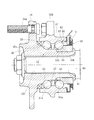
このような回転速度検出装置付き車輪用軸受装置の一例として図8に示すような構造が知られている。この回転速度検出装置付き車輪用軸受装置は、懸架装置を構成するナックル(図示せず)に支持固定され、固定部材となる外方部材51と、この外方部材51に複列の転動体(ボール)53、53を介して内挿された内方部材52とを有し、外方部材51は車体取付フランジ51bを外周に一体に有し、内周には複列の外側転走面51a、51aが形成されている。一方、内方部材52は、前記した外方部材51の外側転走面51a、51aに対向する複列の内側転走面55a、56aが形成されている。これら複列の内側転走面55a、56aのうち一方の内側転走面55aはハブ輪55の外周に一体形成され、他方の内側転走面56aは、ハブ輪55の内側転走面55aから軸方向に延びる円筒状の小径段部55bに圧入された内輪56の外周に形成されている。そして、複列の転動体53、53がこれら両転走面間にそれぞれ収容され、保持器57、57によって転動自在に保持されている。
A structure as shown in FIG. 8 is known as an example of such a wheel bearing device with a rotational speed detection device. This wheel bearing device with a rotational speed detection device is supported and fixed to a knuckle (not shown) constituting a suspension device, and an
ハブ輪55は、外周に車輪(図示せず)を取り付けるための車輪取付フランジ54を一体に有し、この車輪取付フランジ54の円周等配位置には車輪を固定するためのハブボルト54aが植設されている。また、ハブ輪55の内周には、図示しない等速自在継手を構成する外側継手部材60のステム部61が内嵌されるセレーション55cが形成されている。内方部材52は、このハブ輪55と内輪56を指す。そして、外方部材51の端部にはシール58、59が装着され、軸受内部に封入された潤滑グリースの漏洩と、外部から軸受内部に雨水やダスト等が侵入するのを防止している。
The
ここで、外方部材51の端部には回転速度検出装置62が取り付けられている。この回転速度検出装置62は、エンコーダ63とセンサ64とを備えており、図9に拡大して示すように、エンコーダ63は、周方向交互に異なる磁性の磁極が設けられた円筒形のプラスチックマグネット65と、その内周側に一体的に重合された非磁性材料からなるベース66とからなる。
Here, a
一方、センサ64は、ICチップを合成樹脂からなる保護カバーでモールドされたホールICからなる。センサ64の保護カバーは、ICチップが埋設される直方体形状の本体部67と、この本体部67に連接されるL字形状の係止片68とからなり、側面から見てコの字形となるように形成されている。また、係止片68の内面に凸部69が設けられ、本体部67の上面からコード線70が引き出されている。そして、センサ64は、外方部材51の端部に支持環体71を介して装着されている。
On the other hand, the
支持環体71は、複数段にプレス成形された環状鉄板からなり、外方部材51の端部内周に圧入される第1円筒部72と、この第1円筒部72から径方向外方に立ち上がる第1環状板部73と、第1環状板部73から外端に連接される第2円筒部74と、第2円筒部74から径方向内方に立ち下がる第2環状板部75と、第2環状板部75から軸方向に延びる第3円筒部76とを備えている。なお、第2環状板部74の周方向の一箇所には、径方向に貫通するセンサポケット77が開口され、また、このセンサポケット77に対応して、第2環状板部75には係合孔78が設けられている。そして、支持環体71のセンサポケット77にセンサ64の本体部67を径方向から差し入れて、係止片69を支持環体71の係合孔78に係入させて固定している。
The
シール59は、断面L字状に形成された第1のシール板79と、この第1のシール板79に対向し、断面L字状に形成された第2のシール板80とからなる。この第2のシール板80は、内輪56に外嵌される円筒部80aと、この円筒部80aから径方向外方に延びる立板部80bとからなる。
The
一方、第1のシール板79は、前記支持環体71の第3円筒部76に内嵌され、断面L字状に形成された芯金81と、この芯金81に一体に加硫接着され、前記第2のシール板80の立板部80bに摺接するサイドリップ82aと、円筒部80aに摺接する一対のラジアルリップ82b、82cとからなるシール部材82とを有している。
On the other hand, the
このように、支持環体71において、センサ64よりも外側にシール59が設けられているので、エンコーダ63とセンサ64との対向間隙に外部からの異物が侵入するのを防止することができ、検出精度を長期間に亘って高く維持できると共に、センサ64を支持環体71に対して径方向に差し入れて取り付けるようにしているので、エンコーダ63とセンサ64との相対位置のずれを防止することができ、検出精度を高精度に維持することができる。
しかしながら、こうした従来の回転速度検出装置付き車輪用軸受装置は、外方部材51の端部に、複数段にプレス成形された環状鉄板からなる支持環体71を介してセンサ64が装着され、このセンサ64をエンコーダ63に対向配置させているため、エンコーダ63とセンサ64との相対位置のずれを防止することができ、検出精度を高精度に維持することができる特徴を有しているが、以下に列挙する問題点も内在している。すなわち、
1.センサ64が支持環体71の径方向に差し入れられているため、センサ64およびコード線70が外方部材51から径方向外方側に張り出してナックルと干渉する。この干渉を回避するためには、ナックルに凹所等の何らかの追加工が必要となり、コストアップの要因となる。
2.センサ63の本体部67は、支持環体71に対して、この本体部67に連接されるL字形状の樹脂製係止片68で固定されているため、飛び石等による樹脂の欠けや脱落、あるいは腐食等が発生し、耐久性の面で信頼性が低い。
3.また、支持環体71のセンサポケット77にセンサ64の本体部67を径方向から差し入れ、係止片69を支持環体71の係合孔78に係入させて固定するタイプであるので、このセンサ64の係入部からダスト等が軸受内部に異物が侵入するのは否めない。
However, in such a conventional wheel bearing device with a rotational speed detecting device, a
1. Since the
2. Since the
3. Further, since the
本発明は、このような事情に鑑みてなされたもので、コンパクト化と共に、検出部に異物が侵入するのを防止し、耐久性と信頼性を向上させた回転速度検出装置付き車輪用軸受装置を提供することを目的としている。 SUMMARY OF THE INVENTION The present invention has been made in view of such circumstances, and has a wheel bearing device with a rotational speed detection device that is compact and prevents foreign matter from entering the detection portion and has improved durability and reliability. The purpose is to provide.
係る目的を達成すべく、本発明のうち請求項1記載の発明は、内周に複列の外側転走面が形成された外方部材と、一端部に車輪を取り付けるための車輪取付フランジを一体に有し、外周に軸方向に延びる円筒状の小径段部が形成されたハブ輪、およびこのハブ輪の小径段部に圧入された少なくとも一つの内輪とからなり、外周に前記複列の外側転走面に対向する内側転走面が形成された内方部材と、前記両転走面間に転動自在に収容された複列の転動体とを備え、前記内方部材の端部に装着されたエンコーダと、このエンコーダに所定のすきまを介して対峙され、前記外方部材の端部にセンサキャップを介して装着された回転速度センサとを有する回転速度検出装置付き車輪用軸受装置において、前記回転速度センサが、一体モールドされた鋼板製の固定片と、この固定片を覆うような袖状の固定部を有し、前記センサキャップの軸方向に装着されている構成を採用した。
In order to achieve the object, the invention according to
このように、回転速度検出装置付き車輪用軸受装置において、回転速度センサが、一体モールドされた鋼板製の固定片と、この固定片を覆うような袖状の固定部を有し、センサキャップの軸方向に装着されているので、回転速度センサはセンサキャップに対して強固に固定され、従来のように、飛び石等による係止部の欠けや脱落、あるいは腐食等が発生することはなく、耐久性と信頼性を向上させることができる。また、回転速度センサおよびハーネスが外方部材から径方向外方側に張り出してナックルと干渉することはなく、従来のように、干渉を回避するためのナックル追加工が不要となって低コスト化を図ることができる。 Thus, in the wheel bearing device with a rotational speed detection device, the rotational speed sensor has a steel plate fixing piece integrally molded and a sleeve-like fixing portion covering the fixing piece, and the sensor cap Since it is mounted in the axial direction, the rotation speed sensor is firmly fixed to the sensor cap, and there is no occurrence of chipping or dropping of the locking part due to stepping stones, corrosion, etc. And reliability can be improved. In addition, the rotational speed sensor and harness do not protrude radially outward from the outer member and do not interfere with the knuckle, reducing the cost by eliminating the need for additional knuckle work to avoid interference as in the past. Can be achieved.
また、請求項2に記載の発明は、前記センサキャップが鋼板をプレス成形により円環状に形成され、前記外方部材の端部外周に圧入される円筒状の嵌合部と、この嵌合部から径方向内方に延びる底部とを有し、この底部の周方向一箇所にセンサ孔と、このセンサ孔の近傍に係止孔が開口されると共に、前記係止孔に前記固定片を嵌合し、その先端部を塑性変形させることにより、前記回転速度センサが前記センサキャップに密着した状態で一体固定されている。これにより、回転速度センサは鋼板製のセンサキャップに対して強固に固定されると共に、回転速度センサの固定部とセンサキャップとの密着により、係止孔と固定片および検出部とセンサ孔との係止部から磁性粉末等の異物が侵入するのを防止することができ、車輪の回転速度検出の信頼性を向上させることができる。 According to a second aspect of the present invention, the sensor cap is formed in an annular shape by press forming a steel plate, and a cylindrical fitting portion that is press-fitted into the outer periphery of the end portion of the outer member, and the fitting portion. A sensor hole at one location in the circumferential direction of the bottom, a locking hole is opened in the vicinity of the sensor hole, and the fixing piece is fitted into the locking hole. In addition, the rotational speed sensor is integrally fixed in close contact with the sensor cap by plastically deforming the tip portion. As a result, the rotation speed sensor is firmly fixed to the sensor cap made of steel plate, and the locking hole, the fixing piece, the detection section, and the sensor hole are brought into close contact with each other by the close contact between the rotation speed sensor fixing section and the sensor cap. It is possible to prevent foreign matters such as magnetic powder from entering from the locking portion, and to improve the reliability of detecting the rotational speed of the wheel.
好ましくは、請求項3に記載の発明のように、前記回転速度センサの位相が、前記センサキャップの底部に対して水平位置になるように配置されていれば、センサキャップ内に侵入した雨水等がこの回転速度センサ近傍に滞留するのを防止すると共に、ハーネスの取り巻きが簡素化でき、組立作業性が一段と向上する。 Preferably, as in the invention described in claim 3, if the rotational speed sensor is arranged so that the phase of the rotational speed sensor is in a horizontal position with respect to the bottom of the sensor cap, rainwater or the like that has entered the sensor cap Is prevented from staying in the vicinity of the rotational speed sensor, and the winding of the harness can be simplified, and the assembling workability is further improved.
また、請求項4に記載の発明のように、前記回転速度センサとセンサキャップとの間にパッキンが介在されていれば検出部の密封性が一層向上する。
Moreover, if the packing is interposed between the said rotational speed sensor and a sensor cap like invention of
また、請求項5に記載の発明は、前記センサキャップと回転側部材、すなわち、内輪あるいは等速自在継手との間に微小なすきまが形成されてラビリンスシールが構成されているので、自動車の完成品メーカの組立ラインへの搬送時を含む、ハブ輪の内径に外側継手部材を嵌合する以前の状態でも、エンコーダと回転速度センサの検出部との間に外部から磁性粉末等の異物が侵入するのを防止できると共に、インボード側のシールと組み合わされて、雨水や泥水、あるいはダスト等が軸受内部に異物が侵入するのを確実に防止することができる。したがって、車輪の回転速度検出の信頼性向上と共に、軸受の耐久性の向上を図ることができる。
In the invention according to
好ましくは、請求項6に記載の発明のように、前記センサキャップが、その底部から軸方向に突設された舌片を有し、この舌片と等速自在継手を構成する外側継手部材との間に微小な径方向すきまが形成されてラビリンスシールが構成されているので、軸受内部に異物が侵入するのを一層防止することができる。さらに、このラビリンスシールにより、従来、外側継手部材に装着されていたシール装置を廃止することができる。したがって、部品点数と組立工数の削減ができ、トータルコストの低減に大きく貢献することができる。
Preferably, as in the invention described in
本発明に係る回転速度検出装置付き車輪用軸受装置は、内周に複列の外側転走面が形成された外方部材と、一端部に車輪を取り付けるための車輪取付フランジを一体に有し、外周に軸方向に延びる円筒状の小径段部が形成されたハブ輪、およびこのハブ輪の小径段部に圧入された少なくとも一つの内輪とからなり、外周に前記複列の外側転走面に対向する内側転走面が形成された内方部材と、前記両転走面間に転動自在に収容された複列の転動体とを備え、前記内方部材の端部に装着されたエンコーダと、このエンコーダに所定のすきまを介して対峙され、前記外方部材の端部にセンサキャップを介して装着された回転速度センサとを有する回転速度検出装置付き車輪用軸受装置において、前記回転速度センサが、一体モールドされた鋼板製の固定片と、この固定片を覆うような袖状の固定部を有し、前記センサキャップの軸方向に装着されているので、回転速度センサはセンサキャップに対して強固に固定され、従来のように、飛び石等による係止部の欠けや脱落、あるいは腐食等が発生することはなく、耐久性と信頼性を向上させることができる。また、回転速度センサおよびハーネスが外方部材から径方向外方側に張り出してナックルと干渉することはなく、従来のように、干渉を回避するためのナックル追加工が不要となって低コスト化を図ることができる。 The wheel bearing device with a rotational speed detection device according to the present invention integrally has an outer member having a double row outer raceway formed on the inner periphery and a wheel mounting flange for mounting the wheel at one end. A hub wheel having a cylindrical small-diameter step portion extending in the axial direction on the outer periphery, and at least one inner ring press-fitted into the small-diameter step portion of the hub wheel, and the outer circumferential rolling surface of the double row on the outer periphery. And an inner member formed with an inner rolling surface opposite to the inner rolling surface, and a double row rolling element that is slidably accommodated between the both rolling surfaces, and is attached to an end of the inner member. In the wheel bearing device with a rotational speed detection device, comprising: an encoder; and a rotational speed sensor that is opposed to the encoder through a predetermined gap and is attached to an end of the outer member through a sensor cap. Speed sensor is made of integrally molded steel plate Since it has a fixed piece and a sleeve-shaped fixed part that covers the fixed piece and is mounted in the axial direction of the sensor cap, the rotational speed sensor is firmly fixed to the sensor cap, In addition, there is no occurrence of chipping or dropping off of the locking portion due to stepping stones, corrosion, or the like, and durability and reliability can be improved. In addition, the rotational speed sensor and harness do not protrude radially outward from the outer member and do not interfere with the knuckle, reducing the cost by eliminating the need for additional knuckle work to avoid interference as in the past. Can be achieved.
内周に複列の外側転走面が形成された外方部材と、一端部に車輪を取り付けるための車輪取付フランジを一体に有し、外周に前記複列の外側転走面に対向する一方の内側転走面と、この内側転走面から軸方向に延びる円筒状の小径段部が形成されたハブ輪、およびこのハブ輪の小径段部に圧入され、外周に前記複列の外側転走面に対向する他方の内側転走面が形成された内輪とからなる内方部材と、前記両転走面間に転動自在に収容された複列の転動体とを備え、前記内輪の端部に装着されたエンコーダと、このエンコーダに所定の軸方向すきまを介して対峙され、前記外方部材の端部にセンサキャップを介して装着された回転速度センサとを有する回転速度検出装置付き車輪用軸受装置において、前記センサキャップが鋼板をプレス成形により円環状に形成され、前記外方部材の端部外周に圧入される円筒状の嵌合部と、この嵌合部から径方向内方に延びる底部とを有し、この底部の周方向一箇所にセンサ孔と、このセンサ孔の近傍に係止孔が開口され、鋼板製の固定片が一体モールドされ、かつこの固定片を覆うような袖状の固定部を有する回転速度センサが前記センサキャップの軸方向に装着されると共に、前記係止孔に前記固定片を嵌合し、その先端部を塑性変形させることにより、前記回転速度センサが前記センサキャップに密着した状態で一体固定されている。 An outer member having a double row outer raceway formed on the inner periphery, and a wheel mounting flange for attaching a wheel to one end of the outer member are integrated, and the outer periphery faces the double row outer raceway. And a hub ring formed with a cylindrical small-diameter step portion extending in the axial direction from the inner rolling surface, and a small-diameter step portion of the hub ring. An inner member comprising an inner ring on which the other inner rolling surface facing the running surface is formed, and a double row rolling element that is slidably accommodated between the both rolling surfaces. With a rotational speed detection device having an encoder mounted on the end and a rotational speed sensor facing the encoder through a predetermined axial clearance and mounted on the end of the outer member through a sensor cap In wheel bearing devices, the sensor cap is used to press form steel plates. A cylindrical fitting portion that is formed in a circular shape and is press-fitted into the outer periphery of the end portion of the outer member, and a bottom portion that extends radially inward from the fitting portion. A rotation speed sensor having a sensor hole at a location, a locking hole in the vicinity of the sensor hole, a steel plate fixing piece integrally molded, and a sleeve-like fixing portion covering the fixing piece is the sensor. The rotational speed sensor is integrally fixed in close contact with the sensor cap by being mounted in the axial direction of the cap, and by fitting the fixing piece into the locking hole and plastically deforming the distal end portion thereof. Yes.
以下、本発明の実施の形態を図面に基づいて詳細に説明する。
図1は、本発明に係る回転速度検出装置付き車輪用軸受装置の実施形態を示す縦断面図、図2は、図1の側面図である。なお、以下の説明では、車両に組み付けた状態で車両の外側寄りとなる側をアウトボード側(図面左側)、中央寄り側をインボード側(図面右側)という。
Hereinafter, embodiments of the present invention will be described in detail with reference to the drawings.
FIG. 1 is a longitudinal sectional view showing an embodiment of a wheel bearing device with a rotational speed detection device according to the present invention, and FIG. 2 is a side view of FIG. In the following description, the side closer to the outer side of the vehicle when assembled to the vehicle is referred to as the outboard side (left side in the drawing), and the side closer to the center is referred to as the inboard side (right side in the drawing).
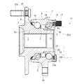
この回転速度検出装置付き車輪用軸受装置は駆動輪用であって、ハブ輪1と複列の転がり軸受とをユニット化した構成を備えている。
回転速度検出装置付き車輪用軸受装置2は、内方部材3と外方部材4と複列の転動体(ボール)5、5とを有し、内方部材3は、外周に複列の内側転走面1a、6aが形成されている。これら複列の内側転走面1a、6aのうち一方の内側転走面1aはハブ輪1の外周に、他方の内側転走面6aは内輪6の外周にそれぞれ一体に形成されている。この場合、内方部材3はハブ輪1と、このハブ輪1の内側転走面1aから軸方向に延びる円筒状の小径段部1bに圧入された内輪6とを指す。
This wheel bearing device with a rotational speed detection device is for a drive wheel and has a configuration in which the
The
一方、外方部材4は、S53C等の炭素0.40〜0.80wt%を含む中炭素鋼からなり、外周に車体(図示せず)に取り付けるための車体取付フランジ4bを一体に有している。内周には前記複列の内側転走面1a、6aに対向する複列の外側転走面4a、4aが形成され、高周波焼入れによって表面硬さを58〜64HRCの範囲に硬化層が形成されている。そして、複列の転動体5、5がこれら両転走面1a、4aおよび6a、4a間にそれぞれ収容され、保持器7、7によって転動自在に保持されている。また、外方部材4の端部にはシール8、9が装着され、軸受内部に封入された潤滑グリースの漏洩と、外部から軸受内部に雨水やダスト等が侵入するのを防止している。ここで転動体5、5をボールとした複列アンギュラ玉軸受を例示したが、これに限らず転動体に円すいころを使用した複列円すいころ軸受であっても良い。
On the other hand, the
ハブ輪1は、S53C等の炭素0.40〜0.80wt%を含む中炭素鋼からなり、アウトボード側の端部に車輪(図示せず)を取り付けるための車輪取付フランジ10を一体に有し、この車輪取付フランジ10の周方向等配位置にハブボルト10aが植設されている。また、アウトボード側のシール8が摺接するシールランド部から内側転走面1aおよび小径段部1bに亙って高周波焼入れによって表面硬さを58〜64HRCの範囲に硬化層が形成されている。これにより、車輪取付フランジ10の基部となるシールランド部は耐摩耗性が向上するばかりでなく、車輪取付フランジ10に負荷される回転曲げ荷重に対して充分な機械的強度を有し、ハブ輪1の耐久性が一層向上する。
The
インボード側のシール9は、図3に拡大して示すように、内輪6と外方部材4にそれぞれ装着された第1および第2の環状のシール板11、12を有している。これらシール板11、12は、それぞれ円筒部11a、12aと立板部11b、12bとでなる断面L字状に形成されて互いに対向している。第1のシール板11の立板部11bには、軸受の軸方向外方側に磁性体粉が混入されたエンコーダ13が一体に加硫接着されている。このエンコーダ13は、周方向に交互に磁極N、Sが形成されたゴム磁石からなり、車輪回転速度の検出用のロータリエンコーダを構成している。
The inboard-
第2のシール板12は、第1のシール板11の立板部11bに摺接するサイドリップ14aと円筒部11aに摺接するラジアルリップ14b、14cとを一体に有するシール部材14が加硫接着されている。そして、第2のシール板12の円筒部12aと、第1のシール板11の立板部11bの先端とは僅かな径方向すきまを介して対峙され、このすきまでラビリンスシール15を構成している。
The
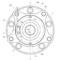
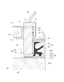
本実施形態では、図1に示すように、外方部材4のインボード側の端部にセンサキャップ16を介して回転速度センサ17が装着されている。センサキャップ16は、図4および図5に示すように、耐食性を有する非磁性ステンレス等の鋼板をプレス成形により断面コの字状で全体が円環状に形成され、外方部材4の端部外周に圧入される円筒状の嵌合部16a(図1参照)と、この嵌合部16aから径方向内方に延びる底部16bと、底部16bから軸方向に突設された舌片16cとからなる。なお、センサキャップ16の底部16bの上下方向には、一対のベント孔19、19が形成され、センサキャップ16内に侵入した雨水等を排出する。このベント孔19は、一箇所であっても、また、積極的に形成しなくとも良い。
In the present embodiment, as shown in FIG. 1, a
底部16bの周方向一箇所に回転速度センサ17が装着されるセンサ孔18aと、このセンサ孔18aの近傍に係止孔18bが開口されている。そして、センサ孔18aの内部に回転速度センサ17が軸方向に装着されて固定される。これにより、回転速度センサ17および後述するハーネス20が外方部材4から径方向外方側に張り出してナックル(図示せず)と干渉することはない。したがって、従来のように、干渉を回避するためのナックル追加工が不要となって低コスト化を図ることができる。また、回転速度センサ17が装着される位相は、図2に示すように、センサキャップ16の底部16bに対して、水平位置になるように配置されている。したがって、例えセンサキャップ16内に雨水等が侵入したとしても、この回転速度センサ17近傍に滞留するのを防止すると共に、ハーネス20の取り巻きが簡素化でき、組立作業性が一段と向上する。
A
回転速度センサ17は、後述する固定片17aと共に合成樹脂で直方体形状に一体モールド成形され、ホール素子、磁気抵抗素子(MR素子)等、磁束の流れ方向に応じて特性を変化させる磁気検出素子と、この磁気検出素子の出力波形を整える波形成形回路が組み込まれたICとからなる。
The
なお、本実施形態では、回転速度検出装置として、エンコーダ13と、ホール素子等の磁気検出素子からなる回転速度センサ17とで構成されたアクティブタイプの回転速度検出装置を例示したが、本発明に係る回転速度検出装置はこれに限らず、例えば、磁気エンコーダと、磁石と巻回された環状のコイル等とセンサの組み合わせおよびエンコーダが凹凸形状の磁性リングタイプ等からなるパッシブタイプであっても良い。
In the present embodiment, as an example of the rotational speed detection device, an active type rotational speed detection device including the
図5に示すように、回転速度センサ17の固定片17aは、耐食性を有する非磁性ステンレス等の鋼板からなり、センサキャップ16に開口された係止孔18bに嵌挿されると共に、その先端部を塑性変形させてセンサキャップ16に加締固定されている。また、回転速度センサ17の検出部17bは、センサキャップ16のセンサ孔18a内に突出し、前記エンコーダ(図示せず)に所定の軸方向すきまを介して対峙している。これにより、回転速度センサ17は、鋼板製のセンサキャップ16に対して強固に固定され、従来のように、飛び石等による係止部の欠けや脱落、あるいは腐食等が発生することはなく、耐久性と信頼性を向上させることができる。
As shown in FIG. 5, the fixed
また、回転速度センサ17には袖状に張り出した固定部17cが形成されており、鋼板製の固定片17aを覆っている。この固定部17cとセンサキャップ16とを密着させることにより、係止孔18bと固定片17aとの係止部および検出部17bとセンサ孔18aとの係止部から磁性粉末等の異物が侵入するのを防止することができ、車輪の回転速度検出の信頼性を向上させることができる。
Further, the
車輪(図示せず)の回転に伴って内輪6と共にエンコーダ13が回転すると、このエンコーダ13に対向する回転速度センサ17の出力が変化する。この回転速度センサ17の出力が変化する周波数は車輪の回転速度に比例するため、回転速度センサ17の出力信号を回転速度センサ17の端部から導出したハーネス20を介して図示しない制御器に入力すれば、ABSを適切に制御することができる。
When the
ここで、図1において、内輪6の端面6bは、等速自在継手を構成する外側継手部材21の肩部21aの端面と突合せ状態で組み立てられているが、この肩部21aと前記センサキャップ16の舌片16cとの間には微小な径方向すきまが形成され、ラビリンスシール22が構成されている。さらに、舌片16cと内輪6の端面6bとを微小な軸方向すきまを介して全周に亙り近接対向させ、ラビリンスシール23の構成としても良い。その場合、自動車の完成品メーカの組立ラインへの搬送時を含む、ハブ輪1の内径に外側継手部材21を嵌合する以前の状態でも、エンコーダ13と回転速度センサ17の検出部17bとの間に、外部から磁性粉末等の異物が侵入するのを防止できると共に、前記シール9と組み合わされて、雨水や泥水、あるいはダスト等が軸受内部に異物が侵入するのを確実に防止することができる効果を有することになる。したがって、車輪の回転速度検出の信頼性向上と共に、軸受の耐久性の向上を図ることができる。さらに、このラビリンスシール22、23により、従来、外側継手部材21に装着されていたシール装置を廃止することができる。したがって、部品点数と組立工数の削減ができ、トータルコストの低減に大きく貢献することができる。
Here, in FIG. 1, the
前述した実施形態は、駆動輪を回転自在に支承する回転速度検出装置付き車輪用軸受装置に関するものであるが、本発明はこうした駆動輪側に限らず、従動輪側の回転速度検出装置付き車輪用軸受装置であっても良い。この場合、図示はしないが、センサキャップが、外方部材の端部外周に圧入される円筒状の嵌合部と、この嵌合部から径方向内方に延びる底部とからなるカップ状に形成される。これにより、外方部材の開口部を完全に閉塞することができ、雨水や泥水、あるいはダスト等が軸受内部に異物が侵入するのを確実に防止することができる。また、ここでは、ハブ輪1に一つの内輪6が圧入された、所謂第3世代構造を例示したが、これに限らず、図示はしないがハブ輪に一対の内輪が圧入された、所謂第1または第2世代構造であっても良い。
The embodiment described above relates to a wheel bearing device with a rotational speed detection device that rotatably supports a drive wheel, but the present invention is not limited to such a drive wheel side, and the wheel with a rotational speed detection device on the driven wheel side. A bearing device may be used. In this case, although not shown, the sensor cap is formed in a cup shape including a cylindrical fitting portion press-fitted to the outer periphery of the end portion of the outer member and a bottom portion extending radially inward from the fitting portion. Is done. Thereby, the opening part of an outer member can be obstruct | occluded completely, and it can prevent reliably that a foreign material penetrate | invades rainwater, muddy water, or a dust etc. in the inside of a bearing. In addition, here, a so-called third generation structure in which one
図6は、本発明に係る回転速度検出装置付き車輪用軸受装置の他の実施形態で、回転速度センサの固定構造を示す要部拡大図である。なお、前述した実施形態と同一部品同一部位には同じ符号を付してその詳細な説明を省略する。 FIG. 6 is an enlarged view of a main part showing a fixing structure of a rotation speed sensor in another embodiment of the wheel bearing device with a rotation speed detection apparatus according to the present invention. In addition, the same code | symbol is attached | subjected to the same components same site as embodiment mentioned above, and the detailed description is abbreviate | omitted.
本実施形態では、回転速度センサ17は、ゴム等の高分子材からなるパッキン24を介してセンサキャップ16に密着された状態で加締固定されている。これにより、係止孔18bと固定片17aとの係止部および検出部17bとセンサ孔18aとの係止部から磁性粉末等の異物が侵入するのを一層防止することができ、車輪の回転速度検出の信頼性を向上させることができる。
In this embodiment, the
なお、回転速度センサ17の固定手段として、回転速度センサ17に一体モールドされた鋼板製の固定片17aを、センサキャップ16に開口された係止孔18bに嵌挿すると共に、その先端部を塑性変形させてセンサキャップ16に加締固定したものを例示したが、これに限らず、例えば、図7に示すように、回転速度センサ25の固定部17cにリベットからなる固定片26を一体モールドし、この固定片26の先端を塑性変形させてセンサキャップ16に加締固定するようにしても良い。これにより、回転速度センサ25の検出部17bの密封性が一段と向上する。
As a fixing means for the
以上、本発明の実施の形態について説明を行ったが、本発明はこうした実施の形態に何等限定されるものではなく、あくまで例示であって、本発明の要旨を逸脱しない範囲内において、さらに種々なる形態で実施し得ることは勿論のことであり、本発明の範囲は、特許請求の範囲の記載によって示され、さらに特許請求の範囲に記載の均等の意味、および範囲内のすべての変更を含む。 The embodiment of the present invention has been described above, but the present invention is not limited to such an embodiment, and is merely an example, and various modifications can be made without departing from the scope of the present invention. Of course, the scope of the present invention is indicated by the description of the scope of claims, and further, the equivalent meanings described in the scope of claims and all modifications within the scope of the scope of the present invention are included. Including.
本発明に係る車輪用軸受装置は、駆動輪用、従動輪用に係らず、回転速度検出装置が内蔵されたあらゆる構造の回転速度検出装置付き車輪用軸受装置に適用することができる。 The wheel bearing device according to the present invention can be applied to a wheel bearing device with a rotational speed detection device having any structure in which the rotational speed detection device is incorporated, regardless of whether it is for driving wheels or driven wheels.
1・・・・・・・・・・・・・・・・ハブ輪
1a、6a・・・・・・・・・・・・内側転走面
1b・・・・・・・・・・・・・・・小径段部
2・・・・・・・・・・・・・・・・複列の転がり軸受
3・・・・・・・・・・・・・・・・内方部材
4・・・・・・・・・・・・・・・・外方部材
4a・・・・・・・・・・・・・・・外側転走面
4b・・・・・・・・・・・・・・・車体取付フランジ
5・・・・・・・・・・・・・・・・転動体
6・・・・・・・・・・・・・・・・内輪
6b・・・・・・・・・・・・・・・端面
7・・・・・・・・・・・・・・・・保持器
8・・・・・・・・・・・・・・・・アウトボード側のシール
9・・・・・・・・・・・・・・・・インボード側のシール
10・・・・・・・・・・・・・・・車輪取付フランジ
10a・・・・・・・・・・・・・・ハブボルト
11・・・・・・・・・・・・・・・第1のシール板
11a、12a・・・・・・・・・・円筒部
11b、12b・・・・・・・・・・立板部
12・・・・・・・・・・・・・・・第2のシール板
13・・・・・・・・・・・・・・・エンコーダ
14・・・・・・・・・・・・・・・シール部材
14a・・・・・・・・・・・・・・サイドリップ
14b、14c・・・・・・・・・・ラジアルリップ
15、22、23・・・・・・・・・ラビリンスシール
16・・・・・・・・・・・・・・・センサキャップ
16a・・・・・・・・・・・・・・嵌合部
16b・・・・・・・・・・・・・・底部
16c・・・・・・・・・・・・・・舌片
17、25・・・・・・・・・・・・回転速度センサ
17a、26・・・・・・・・・・・固定片
17b・・・・・・・・・・・・・・検出部
17c・・・・・・・・・・・・・・固定部
18a・・・・・・・・・・・・・・センサ孔
18b・・・・・・・・・・・・・・係止孔
19・・・・・・・・・・・・・・・ベント孔
20・・・・・・・・・・・・・・・ハーネス
21・・・・・・・・・・・・・・・外側継手部材
21a・・・・・・・・・・・・・・肩部
24・・・・・・・・・・・・・・・パッキン
51・・・・・・・・・・・・・・・外方部材
51a・・・・・・・・・・・・・・外側転走面
51b・・・・・・・・・・・・・・車体取付フランジ
52・・・・・・・・・・・・・・・内方部材
53・・・・・・・・・・・・・・・転動体
54・・・・・・・・・・・・・・・車輪取付フランジ
54a・・・・・・・・・・・・・・ハブボルト
55・・・・・・・・・・・・・・・ハブ輪
55a、56a・・・・・・・・・・内側転走面
55b・・・・・・・・・・・・・・小径段部
55c・・・・・・・・・・・・・・セレーション
57・・・・・・・・・・・・・・・保持器
58、59・・・・・・・・・・・・シール
60・・・・・・・・・・・・・・・外側継手部材
61・・・・・・・・・・・・・・・ステム部
62・・・・・・・・・・・・・・・回転速度検出装置
63・・・・・・・・・・・・・・・エンコーダ
64・・・・・・・・・・・・・・・センサ
65・・・・・・・・・・・・・・・プラスチックマグネット
66・・・・・・・・・・・・・・・ベース
67・・・・・・・・・・・・・・・本体部
68・・・・・・・・・・・・・・・係止片
69・・・・・・・・・・・・・・・凸部
70・・・・・・・・・・・・・・・コード線
71・・・・・・・・・・・・・・・支持環体
72・・・・・・・・・・・・・・・第1円筒部
73・・・・・・・・・・・・・・・第1環状板部
74・・・・・・・・・・・・・・・第2円筒部
75・・・・・・・・・・・・・・・第2環状板部
76・・・・・・・・・・・・・・・第3円筒部
77・・・・・・・・・・・・・・・センサポケット
78・・・・・・・・・・・・・・・係合孔
79・・・・・・・・・・・・・・・第1のシール板
80・・・・・・・・・・・・・・・第2のシール板
80a・・・・・・・・・・・・・・円筒部
80b・・・・・・・・・・・・・・立板部
81・・・・・・・・・・・・・・・芯金
82・・・・・・・・・・・・・・・シール部材
82a・・・・・・・・・・・・・・サイドリップ
82b、82c・・・・・・・・・・ラジアルリップ
1 ・ ・ ・ ・ ・ ・ ・ ・ ・ ・ ・
Claims (6)
前記内方部材の端部に装着されたエンコーダと、このエンコーダに所定のすきまを介して対峙され、前記外方部材の端部にセンサキャップを介して装着された回転速度センサとを有する回転速度検出装置付き車輪用軸受装置において、
前記回転速度センサが、一体モールドされた鋼板製の固定片と、この固定片を覆うような袖状の固定部を有し、前記センサキャップの軸方向に装着されていることを特徴とする回転速度検出装置付き車輪用軸受装置。 An outer member having a double-row outer raceway formed on the inner periphery and a wheel mounting flange for mounting a wheel on one end are integrally formed, and a cylindrical small-diameter step portion extending in the axial direction is formed on the outer periphery. An inner member formed on the outer periphery and formed with an inner rolling surface facing the outer rolling surface of the double row, and at least one inner ring press-fitted into a small-diameter step portion of the hub wheel. A double row rolling element housed so as to be freely rollable between both rolling surfaces,
Rotational speed having an encoder attached to the end of the inner member and a rotational speed sensor opposed to the encoder via a predetermined gap and attached to the end of the outer member via a sensor cap In a wheel bearing device with a detection device,
The rotation speed sensor has an integrally molded steel plate fixing piece and a sleeve-like fixing portion covering the fixing piece, and is mounted in the axial direction of the sensor cap. Wheel bearing device with speed detector.
Priority Applications (1)
| Application Number | Priority Date | Filing Date | Title |
|---|---|---|---|
| JP2004113743A JP2005299739A (en) | 2004-04-08 | 2004-04-08 | Wheel bearing unit with rotary speed sensing device |
Applications Claiming Priority (1)
| Application Number | Priority Date | Filing Date | Title |
|---|---|---|---|
| JP2004113743A JP2005299739A (en) | 2004-04-08 | 2004-04-08 | Wheel bearing unit with rotary speed sensing device |
Publications (1)
| Publication Number | Publication Date |
|---|---|
| JP2005299739A true JP2005299739A (en) | 2005-10-27 |
Family
ID=35331520
Family Applications (1)
| Application Number | Title | Priority Date | Filing Date |
|---|---|---|---|
| JP2004113743A Pending JP2005299739A (en) | 2004-04-08 | 2004-04-08 | Wheel bearing unit with rotary speed sensing device |
Country Status (1)
| Country | Link |
|---|---|
| JP (1) | JP2005299739A (en) |
Cited By (3)
| Publication number | Priority date | Publication date | Assignee | Title |
|---|---|---|---|---|
| JP2009108876A (en) * | 2007-10-26 | 2009-05-21 | Ntn Corp | Bearing device for wheel with rotational speed detection device |
| JP2009174703A (en) * | 2007-12-26 | 2009-08-06 | Jtekt Corp | Rolling bearing device with sensor |
| WO2024061291A1 (en) * | 2022-09-20 | 2024-03-28 | 中广核核电运营有限公司 | Adjustment apparatus and adjustment method |
-
2004
- 2004-04-08 JP JP2004113743A patent/JP2005299739A/en active Pending
Cited By (3)
| Publication number | Priority date | Publication date | Assignee | Title |
|---|---|---|---|---|
| JP2009108876A (en) * | 2007-10-26 | 2009-05-21 | Ntn Corp | Bearing device for wheel with rotational speed detection device |
| JP2009174703A (en) * | 2007-12-26 | 2009-08-06 | Jtekt Corp | Rolling bearing device with sensor |
| WO2024061291A1 (en) * | 2022-09-20 | 2024-03-28 | 中广核核电运营有限公司 | Adjustment apparatus and adjustment method |
Similar Documents
| Publication | Publication Date | Title |
|---|---|---|
| JP2005321375A (en) | Bearing device for wheel with rotation speed detector | |
| JP5193562B2 (en) | Wheel bearing device with rotation speed detector | |
| JP4748775B2 (en) | Wheel bearing device with rotation speed detector | |
| JP2006284402A (en) | Bearing device for wheel with rotation speed detection device | |
| JP2007010480A (en) | Bearing apparatus for wheel with rotation speed detection device | |
| JP4784967B2 (en) | Wheel bearing device with rotation speed detector | |
| JP4628049B2 (en) | Wheel bearing device with rotation speed detector | |
| JP4726042B2 (en) | Wheel bearing device with rotation speed detector | |
| JP2006112919A (en) | Bearing device for wheel with rotational speed sensor | |
| JP4953362B2 (en) | Wheel bearing device with rotation speed detector | |
| JP2005300289A (en) | Wheel bearing device equipped with rotation speed detection device | |
| JP2006308396A (en) | Bearing device for wheel with rotating speed detecting device | |
| JP2006349061A (en) | Bearing device with rotational speed detector for wheel | |
| JP4573201B2 (en) | Wheel bearing device with rotation speed detector | |
| JP2008180544A (en) | Bearing device for wheel with revolution detector | |
| JP2005291478A (en) | Bearing device for wheel with rotational speed detection device | |
| JP2005299739A (en) | Wheel bearing unit with rotary speed sensing device | |
| JP4573194B2 (en) | Wheel bearing device with rotation speed detector | |
| JP2008261462A (en) | Bearing device for wheel with rotational speed detector | |
| JP2009162677A (en) | Wheel bearing device with rotation speed detector | |
| JP2008261463A (en) | Bearing device for wheel with rotational speed detector | |
| JP5213464B2 (en) | Wheel bearing device with rotation speed detector | |
| JP2009063529A (en) | Wheel bearing device with rotating speed detector | |
| JP2006329804A (en) | Bearing arrangement for wheel with rotation speed detecting device | |
| JP2006105185A (en) | Bearing device for wheel with rotating speed detector |
Legal Events
| Date | Code | Title | Description |
|---|---|---|---|
| A621 | Written request for application examination |
Free format text: JAPANESE INTERMEDIATE CODE: A621 Effective date: 20070405 |
|
| A977 | Report on retrieval |
Free format text: JAPANESE INTERMEDIATE CODE: A971007 Effective date: 20090729 |
|
| A131 | Notification of reasons for refusal |
Free format text: JAPANESE INTERMEDIATE CODE: A131 Effective date: 20090803 |
|
| A521 | Written amendment |
Free format text: JAPANESE INTERMEDIATE CODE: A523 Effective date: 20091001 |
|
| A02 | Decision of refusal |
Free format text: JAPANESE INTERMEDIATE CODE: A02 Effective date: 20091214 |