JP2005299730A - Method of manufacturing ball bearing race and sealed ball bearing - Google Patents
Method of manufacturing ball bearing race and sealed ball bearing Download PDFInfo
- Publication number
- JP2005299730A JP2005299730A JP2004113256A JP2004113256A JP2005299730A JP 2005299730 A JP2005299730 A JP 2005299730A JP 2004113256 A JP2004113256 A JP 2004113256A JP 2004113256 A JP2004113256 A JP 2004113256A JP 2005299730 A JP2005299730 A JP 2005299730A
- Authority
- JP
- Japan
- Prior art keywords
- groove
- seal
- ring
- seal groove
- ball bearing
- Prior art date
- Legal status (The legal status is an assumption and is not a legal conclusion. Google has not performed a legal analysis and makes no representation as to the accuracy of the status listed.)
- Pending
Links
Images


Landscapes
- Grinding And Polishing Of Tertiary Curved Surfaces And Surfaces With Complex Shapes (AREA)
- Rolling Contact Bearings (AREA)
Abstract
【課題】
軌道溝とシール溝の同心度の改善と共に、シール溝のアキシャル振れの改善及びシール溝の摺動面のあらさを向上する軌道輪の製造方法および密封シールの密封性の向上、低トルク化を可能とする密封玉軸受を提供する。
【解決手段】
熱処理完了品の軌道溝とシール溝を研削する軌道輪の製造方法により、また、密封シールが研削されたシール溝と摺動する玉軸受によって課題の解決を図る。
【選択図】 図1【Task】
Improves the concentricity of the raceway and seal groove, improves the axial runout of the seal groove, improves the roughness of the sliding surface of the seal groove, improves the sealing performance of the seal seal, and reduces torque A sealed ball bearing is provided.
[Solution]
The problem is solved by the manufacturing method of the raceway that grinds the raceway groove and the seal groove of the heat-treated product, and by the ball bearing that slides on the seal groove where the seal seal is ground.
[Selection] Figure 1
Description
本発明は、密封シール付き玉軸受用の軌道輪の製造方法ならびに密封玉軸受に関する。 The present invention relates to a method of manufacturing a race for a ball bearing with a hermetically sealed ball and a sealed ball bearing.
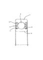
密封玉軸受は、例えば、図6に示す単列玉軸受のように、外輪1、内輪2、玉3、玉を保持する保持器4、及び軸受内に潤滑剤を保持し、かつ外部から水などの異物の浸入を防止する密封シール5から構成されている。
The sealed ball bearing is, for example, an
一般的に、密封シールは、外輪1のシール溝に取付けられ、内輪のシール溝11と密封シールのリップ41とが摺動状態を保ちながら、外部からの水などの侵入を防止し、また、軸受の内部のグリースなどの潤滑剤の漏洩を防止している。
また、密封シールが内輪に取付けられ、外輪と摺動状態を保ちながら使用される用途もある。
Generally, the hermetic seal is attached to the seal groove of the
There is also an application in which a hermetic seal is attached to the inner ring and used while maintaining a sliding state with the outer ring.
近年、小型化、軽量化とコストダウンの影響により、玉軸受が外気に直面する状態が多く、使用環境としては益々厳しくなっている。このような場合、玉軸受に直接水がかかることもあり、玉軸受には、より厳しい耐浸水性が要求される。
この耐浸水性の改善には、密封シールの改良、内輪と密封シールの摺接状態を厳しく管理する方法がある。
In recent years, ball bearings often face outside air due to the downsizing, weight reduction, and cost reduction, and the usage environment has become increasingly severe. In such a case, water may be directly applied to the ball bearing, and the ball bearing is required to have more severe water resistance.
In order to improve the water resistance, there are a method of improving the sealing seal and strictly controlling the sliding contact state between the inner ring and the sealing seal.
しかし、軌道輪は軌道溝、シール溝を旋削加工若しくは鍛造加工で成形した後に、熱処理を行なうが、熱処理を行なうと軌道輪の変形を伴うのが普通である。その後、軌道溝の研削加工を行なうが、シール溝は旋削又は鍛造加工のままであるから、熱処理変形は修正されない。 However, the bearing ring is subjected to heat treatment after the raceway groove and the seal groove are formed by turning or forging process. When the heat treatment is performed, the raceway ring is usually accompanied by deformation. Thereafter, the raceway groove is ground, but since the seal groove remains in the turning or forging process, the heat treatment deformation is not corrected.
従って、取付けられた密封シールのリップとシール溝との摺動状態が必ずしも良好になっていない場合があり、厳しい耐浸水性の要求に対しては、対応できない虞がある。 Therefore, the sliding state between the attached lip of the hermetic seal and the seal groove may not always be satisfactory, and it may not be possible to meet severe water resistance requirements.
この摺動状態の改善に関しての提言がある(例えば、特許文献1を参照)。
特許文献1では、軌道輪の熱処理による変形を修正するために、熱処理後に軌道溝とシール溝を切削加工し、その後に、軌道溝を研削するという加工工程をとっている。
しかしながら、密封性の向上には、軌道溝とシール溝との同心度が良好である必要性は勿論であるが、シール溝のアキシャル振れを改良して密封シールとの摺接状態を改善し、さらに、シール溝のあらさを良好にして、リップの磨耗を低減させる必要がある。
特許文献1では、同心度についての改良であって、シール溝のあらさの改良に関しては言及されていない。
In
However, in order to improve the sealing performance, it is needless to say that the concentricity between the raceway groove and the seal groove is good, but the axial runout of the seal groove is improved to improve the sliding contact state with the seal seal, Furthermore, it is necessary to improve the roughness of the seal groove and reduce the wear of the lip.
In
本発明は、この点に鑑みなされたもので、軌道溝とシール溝との良好な同心度を確保するのは勿論、シール溝のアキシャル振れおよびあらさを改善する軌道輪の製造方法を提供することを目的とし、また、密封シールのリップの耐磨耗性向上、軸受の低トルク化、軸受のトルク変動の低減等を可能とする玉軸受を提供することを目的としている。 The present invention has been made in view of this point, and provides a method of manufacturing a bearing ring that improves axial runout and roughness of the seal groove as well as ensuring good concentricity between the raceway groove and the seal groove. It is another object of the present invention to provide a ball bearing that can improve the wear resistance of the lip of the hermetic seal, reduce the torque of the bearing, reduce the torque fluctuation of the bearing, and the like.
上記の目的を達成するために、本発明は、
旋削工程又は鍛造工程により軌道溝を形成した玉軸受用の軌道輪の素材を、熱処理する工程と、前記熱処理を完了した前記素材の軌道溝を研削する工程を含む玉軸受軌道輪の製造方法において、 さらに、
シール溝を研削する工程を含むことを特徴とする玉軸受軌道輪の製造方法を提供する。
In order to achieve the above object, the present invention provides:
In a ball bearing bearing ring manufacturing method comprising a step of heat-treating a material of a ball bearing ring for which a raceway groove has been formed by a turning process or a forging process, and a step of grinding the raceway groove of the material that has been subjected to the heat treatment. In addition,
A method for manufacturing a ball bearing race is provided, which includes a step of grinding a seal groove.
上記の目的を達成するために、また、本発明は、
軌道溝を研削する工程とシール溝を研削する工程とは同時に行なわれることを特徴とする玉軸受軌道輪の製造方法を提供する。
In order to achieve the above object, the present invention also provides:
A method for manufacturing a ball bearing race is provided, wherein the step of grinding the raceway groove and the step of grinding the seal groove are performed simultaneously.
上記の目的を達成するために、また、本発明は、
軌道溝を研削する工程に続いて、シール溝を研削する工程が行なわれることを含むことを特徴とする玉軸受軌道輪の製造方法を提供する。
In order to achieve the above object, the present invention also provides:
Provided is a method for manufacturing a ball bearing race which includes a step of grinding a seal groove following a step of grinding a raceway groove.
上記の目的を達成するために、本発明は、
内周軌道溝と両端部に内周シール溝を有する外輪と、
前記内周軌道溝に対向する外周軌道溝と前記内周シール溝に対向する外周シール溝とを有する内輪と、
前記外輪と前記内輪との間に介装されたボールと、
前記外輪と前記内輪との間の空間を密封する密封シールとからなる玉軸受において、
前記内周シール溝と前記外周シール溝のうち少なくとも前記外周シール溝は研削面であって、前記密封シールは外輪の内周シール溝に固定され、前記密封シールの内周面に設けられたリップが内輪の外周シール溝と摺動することを特徴とする密封玉軸受を提供する。
In order to achieve the above object, the present invention provides:
An outer ring having an inner circumferential raceway groove and inner circumferential sealing grooves at both ends;
An inner ring having an outer periphery raceway groove facing the inner circumference raceway groove and an outer periphery seal groove facing the inner circumference seal groove;
A ball interposed between the outer ring and the inner ring;
In a ball bearing comprising a hermetic seal that seals a space between the outer ring and the inner ring,
Of the inner peripheral seal groove and the outer peripheral seal groove, at least the outer peripheral seal groove is a grinding surface, and the hermetic seal is fixed to the inner peripheral seal groove of the outer ring, and a lip provided on the inner peripheral surface of the hermetic seal Provides a sealed ball bearing characterized by sliding with an outer peripheral seal groove of an inner ring.
上記の目的を達成するために、また、本発明は、
内周軌道溝と両端部に内周シール溝を有する外輪と、
前記内周軌道溝に対向する外周軌道溝と前記内周シール溝に対向する外周シール溝とを有する内輪と、
前記外輪と前記内輪との間に介装されたボールと、
前記外輪と前記内輪との間の空間を密封する密封シールとからなる玉軸受において、
前記内周シール溝と前記外周シール溝のうち少なくとも前記内周シール溝は研削面であって、前記密封シールは内輪の外周シール溝に固定され、前記密封シールの外周面に設けられたリップが外輪の内周シール溝と摺動することを特徴とする密封玉軸受を提供する。
In order to achieve the above object, the present invention also provides:
An outer ring having an inner circumferential raceway groove and inner circumferential sealing grooves at both ends;
An inner ring having an outer periphery raceway groove facing the inner circumference raceway groove and an outer periphery seal groove facing the inner circumference seal groove;
A ball interposed between the outer ring and the inner ring;
In a ball bearing comprising a hermetic seal that seals a space between the outer ring and the inner ring,
Of the inner peripheral seal groove and the outer peripheral seal groove, at least the inner peripheral seal groove is a grinding surface, the sealing seal is fixed to the outer peripheral sealing groove of the inner ring, and a lip provided on the outer peripheral surface of the sealing seal is provided. Provided is a sealed ball bearing characterized by sliding with an inner peripheral sealing groove of an outer ring.
本発明によれば、軌道溝とシール溝の同心度は勿論、シール溝のアキシャル振れ、およびシール溝のあらさを改善させる軌道輪の製造方法を提供することができる。その結果、リップの耐磨耗性向上、軸受の低トルク化、軸受のトルク変動の低減を可能とした玉軸受を提供できる。 ADVANTAGE OF THE INVENTION According to this invention, the manufacturing method of the bearing ring which improves the axial runout of a seal groove and the roughness of a seal groove can be provided as well as the concentricity of a raceway groove and a seal groove. As a result, it is possible to provide a ball bearing capable of improving the wear resistance of the lip, reducing the torque of the bearing, and reducing the torque fluctuation of the bearing.
以下、本発明に関わる軌道輪の製造方法ならびに玉軸受の実施形態を図面を参照しながら説明する。 Embodiments of a bearing ring manufacturing method and ball bearings according to the present invention will be described below with reference to the drawings.
(実施形態1)
図1を参照しながら、外輪の製造方法の実施形態1について説明する。
(Embodiment 1)
A first embodiment of a method for manufacturing an outer ring will be described with reference to FIG.
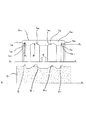
図1は複列玉軸受の外輪の上半分を示す断面図である。 FIG. 1 is a sectional view showing an upper half of an outer ring of a double row ball bearing.
外輪1aの素材1a0(以下、外輪ワーク1a0という)は旋削加工もしくは鍛造加工によって成形され、その後に熱処理工程で所定の硬度を与えられたものである。後述する内輪を含めて外輪用の材料としては、高炭素クロム鋼や、浸炭鋼が使用されている。
A
外輪ワーク1a0は、まず、両端面1a1,1a2を平面研削によって仕上げた後に、外周面1a3を研削加工(一般的には、センタレス加工が多い)によって仕上げる。
The
次に、本図に示す製造工程に入る。本製造工程は、外周面1a3を基準面として支持し、外輪ワーク1a0を軸X2−X2を中心として所定の回転数で回転させる。成形砥石G1は所望の複列の軌道溝と同形状に成形された砥石部G11、G12および両端部の所望の内周シール溝と同形状に成形された砥石部G13,G14を有しており、X1−X1を中心に回転しながら矢印イ方向に移動し、外輪ワーク1a0の軌道溝1a4,1a5および内周シール溝1a6,1a7を同時に研削する。この結果、外輪ワーク1a0の外周面1a3を基準とした場合の軌道溝1a4,1a5のラジアル振れR1とシール溝1a6,1a7のラジアル振れR2との差、いわゆる同心度及び内周シール溝平面部1a61,1a71のアキシャル振れR3が良好になる。軌道溝1a4,1a5は、この研削後、超仕上げ研削をして外輪1aとして完成させる。超仕上げ研削自体は従来周知のものでよい。
Next, the manufacturing process shown in FIG. In this manufacturing process, the outer
以上の製造方法を内輪に当て嵌めた場合について図2を参照しながら説明する。 The case where the above manufacturing method is applied to the inner ring will be described with reference to FIG.
内輪ワーク2a0を作るまでは外輪と同じである。
It is the same as the outer ring until the
まず、内輪ワーク2a0を軸Y2−Y2を中心に所定の回転数で回転させながら、両端面2a1,2a2を平面研削によって仕上げた後、本図に示す製造工程に入る。本製造工程は、センタレス方式によって、所望の軌道溝およびシール溝と同形状に成形された砥石部G21,G22、G23,G24を有する成形砥石G2をY1−Y1を中心に回転させながら矢印ロ方向に移動して、Y2−Y2を中心に回転している内輪ワーク2a0の軌道溝2a4,2a5と外周シール溝2a6,2a7を同時に研削する。この研削後に、内周部2a3の研削をする。この結果、内周部2a3を基準とした場合の軌道溝2a4,2a5のラジアル振れQ1とシール溝の端部円筒面2a62,2a72のラジアル振れQ2との差、いわゆる同心度及び外周シール溝の平面部2a61,2a71のアキシャル振れQ3が良好になる。軌道溝2a4,2a5はこの研削後、超仕上げを行ない内輪2aとして完成させる。超仕上げ研削自体は従来周知のものでよい。
First, both
外輪1aおよび内輪2aは上記の製造方法を採用するので、夫々、外輪軌道溝と内周シール溝および内輪軌道溝と外周シール溝の同心度が良好にできるのは勿論、外輪および内輪のシール溝平面部のアキシャル振れも小さくなる。また、研削仕上げにより、シール溝のあらさが良好になる。特に、図2に示す形状の内輪においては、リップと摺動するシール溝の端部円筒面2a62,2a72および平面部2a61,2a71のあらさを向上させることが重要である。
Since the
さらに、軌動溝に対するシール溝の平行度も向上する。 Furthermore, the parallelism of the seal groove with respect to the rail groove is also improved.
(実施形態2)
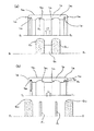
次に、図3(a)、(b)によって実施形態2を説明する。
(Embodiment 2)
Next,
ここで説明する複列の外輪1aは、実施形態1の場合にも説明しているが、本実施形態の製造方法に入る前に、外周面1a3、両端面1a1,1a2の研削加工を既に終えた素材である外輪ワーク1a0である。
The double-row
外周面1a3を基準にして外輪ワーク1a0を軸S2−S2を中心に所定の回転数で回転させながら、かつ、所望の軌道溝と同形状をした2枚の成形砥石G31,G32をS1−S1を中心に回転させながら、矢視ハ方向に移動させ、S2−S2を中心に回転している外輪ワーク1a0の軌道溝1a4,1a5を同時研削する[図3(a)参照]。
Two forming grindstones G 31 having the same shape as a desired raceway groove while rotating the
この研削後に、外周面1a3を基準にし、かつ、研削加工が完了している軌道溝1a4,1a5を回転盤P1、P2によって押さえながら、所望の内周シール溝と同形状に成形されている砥石G43,G44を矢視二方向に移動させて、両端のシール溝1a6,1a7を研削する。[図3(b)参照]
この結果、外周部1a3を基準とした場合の軌道溝1a4,1a5のラジアル振れR4とシール溝1a6,1a7のラジアル振れR5との差、いわゆる同心度及びシール溝の平面1a6,1a7のアキシャル振れR6が良好になる。
After this grinding, the outer
As a result, the difference between the radial runout R 5 Radial runout R 4 and the sealing
以上の方法を内輪にあて嵌めた場合を図4(a)、(b)を参照して説明する。 The case where the above method is applied to the inner ring will be described with reference to FIGS. 4 (a) and 4 (b).
内輪ワークを作るまでは外輪の場合と同じである。 The process is the same as for the outer ring until the inner ring work is made.
内輪ワーク2a0の両端面は研削が完了している。まず、本工程は、外輪ワークの場合と同様に、2枚の成形されている砥石G51,G52をU1−U1を中心に回転させながら矢印ホ方向へ移動させて、U2−U2を中心に回転している内輪ワーク2a0の複列軌道2a4,2a5を同時に研削する。この研削後に、回転盤P3,P4で複列軌道2a4,2a5を押さえながら、V1−V1を中心に回転している砥石G63,G64を矢印へ方向に移動して、V2−V2を中心に回転している内輪ワーク2a0の両端部のシール溝2a6,2a7を研削する。
Both end surfaces of the
この結果、内周部2a3を基準とした場合の軌道溝2a4,2a5のラジアル振れQ4とシール溝の摺動面2a6,2a7のラジアル振れQ5との差、いわゆる同心度及びシール溝の平面2a6,2a7のアキシャル振れQ6が良好になる。
As a result, the difference between the radial runout Q 5 of the radial runout Q 4 and the sealing groove of the sliding
なお、上記実施形態1及び実施形態2では、複列玉軸受について説明したが、単列玉軸受で実施できるのは勿論である。 In the first embodiment and the second embodiment, the double row ball bearing has been described, but it is needless to say that the single row ball bearing can be used.
(実施形態3)
本発明の実施形態3の複列玉軸受Cを図5によって説明する。
(Embodiment 3)
A double-row ball bearing C according to
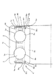
図5は本実施形態の複列玉軸受の上半分断面図である。
本実施形態の軌道輪は、例えば、実施形態1もしくは実施形態2の軌道輪の製造方法と同じ方法によって製造されている。
FIG. 5 is an upper half sectional view of the double row ball bearing of the present embodiment.
The raceway of this embodiment is manufactured by the same method as the raceway manufacturing method of
外輪1aは、複列の内周軌道1a4,1a5を有し両端部には密封シール4,4を嵌合する内周シール溝1a6,1a7を有している。該内周シール溝は研削加工されている。
The
内輪2aは、前記内周軌道に対向する複列の外周軌道2a4,2a5を有し、両端には、シールリップ41と摺接して密封部を形成する外周シール溝2a6,2a7を形成している。
The
外周シール溝2a6,2a7は後述するラジアルリップ411,411と摺接する円筒部2a62,2a72を内輪の両端に設け、前記円筒部の軸受内方にはアキシャルリップ412,412と摺接する平面部2a61,2a71とが設けられている。
The outer
密封シール4,4は、芯金41,41と、芯金41,41の周囲に加硫工程によって焼き付けられているゴムなどの弾性体層43,43からなり、該弾性体層43、43のそれぞれは外周部に前記内周シール溝1a6,1a7と嵌合固定された取付け部44、44を有し、内周部は、前記外周シール溝2a6,2a7と摺接するリップ41、41を有している。
The
該リップ41、41のそれぞれは、内輪の外周シール溝の円筒部2a62,2a72とラジアル方向に当接しているラジアルリップ411、411と内側のシール溝平面部2a61,2a62と当接しているアキシャルリップ412、412とからなっている。
The
ラジアルリップ411、411の場合は、前記円筒部2a62,2a72が研削仕上げされていてあらさが良いためにリップの磨耗が少なく、さらに円筒部2a62,2a72と内輪の軌道溝2a4,2a5との同心度が良いのでリップ圧が一定化し、また、アキシャルリップ412、412の場合は、平面部2a61,2a71が研削仕上げされていてあらさが良いためにリップの磨耗が少なく、さらに、軌動溝2a4,2a5との平行度が良いので平面部2a61,2a71のアキシャル振れが良好になり、リップ圧が一定化する。従って、シールの磨耗が少ないので高耐久密封性およびシール溝の同心度、アキシャル振れが良好なので、低トルク軸受が得られる。さらに、平面部アキシャル振れが小さいので、一回転中のトルクの変動も押さえられる。
In the case of the
なお、図5に示す本実施形態においては、内輪外周シール溝の円筒部2a62,2a72および平面部2a61,2a71はそれぞれラジアルリップ411,411およびアキシャルリップ412,412と摺接するので研削面にする必要がある。ラジアルリップ411,411、アキシャルリップ412,412およびシール溝2a6,2a7で囲まれているそれぞれの空間2a8,2a9は外部から異物が浸入した場合若しくは内部からグリースなど潤滑剤が漏れた場合、それらの溜まり場として必要な空間である。従って、本実施形態に於いては、前記リップと摺接する面以外は研削されていなくてもよいが本実施形態に示されている形式のシール以外の形式も有り、内輪の外周シール溝全体が研削されていれば、これらのシールにも対応できる。軌道輪の製造方法のところで説明したように成形砥石を使用する場合問題なく加工できる。また、本実施形態は内輪回転軸受に関して説明しているが、外輪回転軸受に関しても適用するものである。
In the present embodiment shown in FIG. 5, the
1a:外輪
1a0:外輪ワーク
1a1,1a2:外輪の両端面
1a3:外輪の外周面
1a4,1a5:外輪の軌道溝
1a6,1a7:内周シール溝
1a61,1a71:内周シール溝平面部
2a:内輪
2a0:内輪ワーク
2a1,2a2:内輪の両端面
2a3:内輪の内周面
2a4,2a5:内輪の軌道溝
2a6,2a7:外周シール溝
2a61,2a71:外周シール溝平面部
3:玉
4:密封シール
41:シールリップ
411:ラジアルリップ
412:アキシャルリップ
R1,R4:外輪軌道溝ラジアル振れ
R2,R5:外輪シール溝ラジアル振れ
R3,R6:外輪シール溝平面部アキシャル振れ
Q1、Q4:内輪軌道溝ラジアル振れ
Q2、Q5:内輪シール溝ラジアル振れ
Q3、Q6:内輪シール溝平面部アキシャル振れ
G1,G2,G3,G4、G5、G6:研削砥石
1a:
Claims (5)
シール溝を研削する工程を含むことを特徴とする玉軸受軌道輪の製造方法。 In a ball bearing bearing ring manufacturing method comprising a step of heat-treating a material of a ball bearing ring for which a raceway groove has been formed by a turning process or a forging process, and a step of grinding the raceway groove of the material that has been subjected to the heat treatment. In addition,
A method of manufacturing a ball bearing race, comprising a step of grinding a seal groove.
前記内周軌道溝に対向する外周軌道溝と前記内周シール溝に対向する外周シール溝とを有する内輪と、
前記外輪と前記内輪との間に介装されたボールと、
前記外輪と前記内輪との間の空間を密封する密封シールとからなる玉軸受において、
前記内周シール溝と前記外周シール溝のうち少なくとも前記外周シール溝は研削面であって、前記密封シールは外輪の内周シール溝に固定され、前記密封シールの内周面に設けられたリップが内輪の外周シール溝と摺動することを特徴とする密封玉軸受。 An outer ring having an inner circumferential raceway groove and inner circumferential sealing grooves at both ends;
An inner ring having an outer periphery raceway groove facing the inner circumference raceway groove and an outer periphery seal groove facing the inner circumference seal groove;
A ball interposed between the outer ring and the inner ring;
In a ball bearing comprising a hermetic seal that seals a space between the outer ring and the inner ring,
Of the inner peripheral seal groove and the outer peripheral seal groove, at least the outer peripheral seal groove is a grinding surface, and the hermetic seal is fixed to the inner peripheral seal groove of the outer ring, and a lip provided on the inner peripheral surface of the hermetic seal Seal ball bearing characterized by sliding with the outer peripheral seal groove of the inner ring.
前記内周軌道溝に対向する外周軌道溝と前記内周シール溝に対向する外周シール溝とを有する内輪と、
前記外輪と前記内輪との間に介装されたボールと、
前記外輪と前記内輪との間の空間を密封する密封シールとからなる玉軸受において、
前記内周シール溝と前記外周シール溝のうち少なくとも前記内周シール溝は研削面であって、前記密封シールは内輪の外周シール溝に固定され、前記密封シールの外周面に設けられたリップが外輪の内周シール溝と摺動することを特徴とする密封玉軸受。 An outer ring having an inner circumferential raceway groove and inner circumferential sealing grooves at both ends;
An inner ring having an outer periphery raceway groove facing the inner circumference raceway groove and an outer periphery seal groove facing the inner circumference seal groove;
A ball interposed between the outer ring and the inner ring;
In a ball bearing comprising a hermetic seal that seals a space between the outer ring and the inner ring,
Of the inner peripheral seal groove and the outer peripheral seal groove, at least the inner peripheral seal groove is a grinding surface, the sealing seal is fixed to the outer peripheral sealing groove of the inner ring, and a lip provided on the outer peripheral surface of the sealing seal is provided. A sealed ball bearing that slides with an inner peripheral sealing groove of an outer ring.
Priority Applications (1)
| Application Number | Priority Date | Filing Date | Title |
|---|---|---|---|
| JP2004113256A JP2005299730A (en) | 2004-04-07 | 2004-04-07 | Method of manufacturing ball bearing race and sealed ball bearing |
Applications Claiming Priority (1)
| Application Number | Priority Date | Filing Date | Title |
|---|---|---|---|
| JP2004113256A JP2005299730A (en) | 2004-04-07 | 2004-04-07 | Method of manufacturing ball bearing race and sealed ball bearing |
Publications (1)
| Publication Number | Publication Date |
|---|---|
| JP2005299730A true JP2005299730A (en) | 2005-10-27 |
Family
ID=35331511
Family Applications (1)
| Application Number | Title | Priority Date | Filing Date |
|---|---|---|---|
| JP2004113256A Pending JP2005299730A (en) | 2004-04-07 | 2004-04-07 | Method of manufacturing ball bearing race and sealed ball bearing |
Country Status (1)
| Country | Link |
|---|---|
| JP (1) | JP2005299730A (en) |
Cited By (12)
| Publication number | Priority date | Publication date | Assignee | Title |
|---|---|---|---|---|
| KR100916571B1 (en) * | 2008-01-08 | 2009-09-11 | (주)엠아이티 | Bearing race manufacturing method |
| WO2009147865A1 (en) * | 2008-06-06 | 2009-12-10 | Ntn株式会社 | Swing bearing and method of processing raceway groove of the same |
| JP2012233536A (en) * | 2011-05-02 | 2012-11-29 | Jtekt Corp | Outer race for bearing, its manufacturing method and grinding wheel for orbital surface |
| CN103148104A (en) * | 2013-03-13 | 2013-06-12 | 泛科轴承集团有限公司 | Processing technology of bearing outer ring |
| CN103406819A (en) * | 2013-08-23 | 2013-11-27 | 摩士集团股份有限公司 | Bearing seal groove forming plunge-cut grinding method |
| JP2014211197A (en) * | 2013-04-19 | 2014-11-13 | 日本精工株式会社 | Rolling bearing with seal ring |
| WO2016088994A1 (en) * | 2014-12-02 | 2016-06-09 | 주식회사 베어링아트 | Method for manufacturing outer race of ball bearing and outer race of ball bearing manufactured using same |
| JP2017509850A (en) * | 2014-03-27 | 2017-04-06 | サン−ゴバン パフォーマンス プラスティックス コーポレイション | Rotating shaft housing and seal |
| JP2018173101A (en) * | 2017-03-31 | 2018-11-08 | グローブライド株式会社 | Bearing with magnetic fluid seal |
| WO2020158161A1 (en) * | 2019-01-31 | 2020-08-06 | 日本精工株式会社 | Bearing ring member production method, roller bearing production method, hub unit bearing production method, and vehicle production method |
| CN112975303A (en) * | 2021-03-24 | 2021-06-18 | 中国航发哈尔滨轴承有限公司 | Processing method of light and thin series sealing structure bearing outer ring |
| JP2022009464A (en) * | 2017-09-26 | 2022-01-14 | 日本精工株式会社 | Single row deep groove ball bearings and their manufacturing methods |
-
2004
- 2004-04-07 JP JP2004113256A patent/JP2005299730A/en active Pending
Cited By (23)
| Publication number | Priority date | Publication date | Assignee | Title |
|---|---|---|---|---|
| KR100916571B1 (en) * | 2008-01-08 | 2009-09-11 | (주)엠아이티 | Bearing race manufacturing method |
| WO2009147865A1 (en) * | 2008-06-06 | 2009-12-10 | Ntn株式会社 | Swing bearing and method of processing raceway groove of the same |
| JP2010281352A (en) * | 2008-06-06 | 2010-12-16 | Ntn Corp | Swing bearing and method of processing raceway groove thereof |
| CN102057172A (en) * | 2008-06-06 | 2011-05-11 | Ntn株式会社 | Swing bearing and method of processing raceway groove of the same |
| JP2012233536A (en) * | 2011-05-02 | 2012-11-29 | Jtekt Corp | Outer race for bearing, its manufacturing method and grinding wheel for orbital surface |
| CN103148104A (en) * | 2013-03-13 | 2013-06-12 | 泛科轴承集团有限公司 | Processing technology of bearing outer ring |
| CN103148104B (en) * | 2013-03-13 | 2015-09-23 | 泛科轴承集团有限公司 | The processing technology of bearing outer ring |
| JP2014211197A (en) * | 2013-04-19 | 2014-11-13 | 日本精工株式会社 | Rolling bearing with seal ring |
| CN103406819A (en) * | 2013-08-23 | 2013-11-27 | 摩士集团股份有限公司 | Bearing seal groove forming plunge-cut grinding method |
| CN103406819B (en) * | 2013-08-23 | 2015-05-06 | 摩士集团股份有限公司 | Bearing seal groove forming plunge-cut grinding method |
| US10393268B2 (en) | 2014-03-27 | 2019-08-27 | Saint-Gobain Performance Plastics Corporation | Rotary shaft housing and seal |
| JP2017509850A (en) * | 2014-03-27 | 2017-04-06 | サン−ゴバン パフォーマンス プラスティックス コーポレイション | Rotating shaft housing and seal |
| WO2016088994A1 (en) * | 2014-12-02 | 2016-06-09 | 주식회사 베어링아트 | Method for manufacturing outer race of ball bearing and outer race of ball bearing manufactured using same |
| JP2018173101A (en) * | 2017-03-31 | 2018-11-08 | グローブライド株式会社 | Bearing with magnetic fluid seal |
| JP2022009464A (en) * | 2017-09-26 | 2022-01-14 | 日本精工株式会社 | Single row deep groove ball bearings and their manufacturing methods |
| JP7151854B2 (en) | 2017-09-26 | 2022-10-12 | 日本精工株式会社 | Single row deep groove ball bearing and manufacturing method thereof |
| WO2020158161A1 (en) * | 2019-01-31 | 2020-08-06 | 日本精工株式会社 | Bearing ring member production method, roller bearing production method, hub unit bearing production method, and vehicle production method |
| JPWO2020158161A1 (en) * | 2019-01-31 | 2021-03-11 | 日本精工株式会社 | Manufacturing method of raceway ring member, manufacturing method of rolling bearing, manufacturing method of hub unit bearing and manufacturing method of vehicle |
| CN113348052A (en) * | 2019-01-31 | 2021-09-03 | 日本精工株式会社 | Method for manufacturing raceway ring member, method for manufacturing rolling bearing, method for manufacturing hub unit bearing, and method for manufacturing vehicle |
| JP7140208B2 (en) | 2019-01-31 | 2022-09-21 | 日本精工株式会社 | Method for manufacturing race member, method for manufacturing rolling bearing, method for manufacturing hub unit bearing, and method for manufacturing vehicle |
| US12048984B2 (en) | 2019-01-31 | 2024-07-30 | Nsk Ltd. | Method for producing track ring member, method for producing rolling bearing, method for producing hub unit bearing, and method for producing vehicle |
| CN112975303A (en) * | 2021-03-24 | 2021-06-18 | 中国航发哈尔滨轴承有限公司 | Processing method of light and thin series sealing structure bearing outer ring |
| CN112975303B (en) * | 2021-03-24 | 2022-06-10 | 中国航发哈尔滨轴承有限公司 | Processing method of light and thin series sealing structure bearing outer ring |
Similar Documents
| Publication | Publication Date | Title |
|---|---|---|
| JP4527440B2 (en) | Wheel bearing device and manufacturing method thereof | |
| US6796714B2 (en) | Rolling-bearing unit for wheel support | |
| KR101551316B1 (en) | Bearing roller, bearing, and bearing roller processing method | |
| JP2005299730A (en) | Method of manufacturing ball bearing race and sealed ball bearing | |
| JPH06246546A (en) | Manufacture of bearing ring for rolling bearing | |
| JP4211718B2 (en) | Machining method of raceway surface of outer ring of double row angular contact ball bearing | |
| JP2009024708A (en) | Method for manufacturing rolling ring bearing ring | |
| JP2004092830A (en) | Manufacturing method of wheel bearing unit | |
| CN113348052B (en) | Method for manufacturing raceway ring component, method for manufacturing rolling bearing, method for manufacturing hub unit bearing, and method for manufacturing vehicle | |
| JP2025067505A (en) | Method for manufacturing outer ring of hub unit bearing | |
| CN218598608U (en) | Double-row angular contact ball bearing for silicone oil clutch and processing equipment | |
| JPH0587131A (en) | Thrust ball bearing | |
| JP4064440B1 (en) | Manufacturing method of wheel bearing device | |
| JPH0384218A (en) | Sealed rolling bearing | |
| JP2009024859A (en) | Method for manufacturing rolling ring bearing ring | |
| JP3539770B2 (en) | Roller for self-aligning roller bearing and its processing method | |
| WO2022264880A1 (en) | Wheel bearing device | |
| JP2015028372A (en) | Rolling bearing unit for wheel support | |
| JP4178220B2 (en) | Manufacturing method of disc for variator of full toroidal type continuously variable transmission | |
| JP3851094B2 (en) | Toroidal-type continuously variable transmission and processing method of roller used therefor | |
| JP4581843B2 (en) | Method for manufacturing rolling ring bearing ring | |
| WO2005040626A1 (en) | Sealed roller bearing | |
| JP7331671B2 (en) | Manufacturing method of hub unit bearing | |
| JP2007092793A (en) | Sealed rolling bearing | |
| JP2024136425A (en) | Manufacturing method of hub unit bearing |
Legal Events
| Date | Code | Title | Description |
|---|---|---|---|
| A621 | Written request for application examination |
Effective date: 20070406 Free format text: JAPANESE INTERMEDIATE CODE: A621 |
|
| A977 | Report on retrieval |
Free format text: JAPANESE INTERMEDIATE CODE: A971007 Effective date: 20090424 |
|
| A131 | Notification of reasons for refusal |
Effective date: 20090512 Free format text: JAPANESE INTERMEDIATE CODE: A131 |
|
| A02 | Decision of refusal |
Effective date: 20091006 Free format text: JAPANESE INTERMEDIATE CODE: A02 |