JP2005299714A - Wiring and piping material support - Google Patents
Wiring and piping material support Download PDFInfo
- Publication number
- JP2005299714A JP2005299714A JP2004112754A JP2004112754A JP2005299714A JP 2005299714 A JP2005299714 A JP 2005299714A JP 2004112754 A JP2004112754 A JP 2004112754A JP 2004112754 A JP2004112754 A JP 2004112754A JP 2005299714 A JP2005299714 A JP 2005299714A
- Authority
- JP
- Japan
- Prior art keywords
- support
- rigid plate
- wiring
- plate portions
- fixing
- Prior art date
- Legal status (The legal status is an assumption and is not a legal conclusion. Google has not performed a legal analysis and makes no representation as to the accuracy of the status listed.)
- Granted
Links
Images


Landscapes
- Supports For Pipes And Cables (AREA)
- Installation Of Indoor Wiring (AREA)
Abstract
【課題】
目的の傾斜角度でもって、しかも大きく屈曲(座屈)することなく連続してわん曲した状態で配線・配管材を配線等できて、かつ曲げ強度の大きな配線・配管材の支持具の提供である。
【解決手段】
段差部A1 、空中部等において鞘管(配線・配管材)Pを下方から支持するための支持具Sであって、全体が細長い金属板で構成されて、人が乗っても変形しない程度の剛性を有する剛性板部1と、該剛性板部1どうしを連結する連結板部2とが、長手方向に沿って交互に形成され、各連結板部2は、相前後する剛性板部1を相対的に適宜角度に屈曲させるべく変形可能になっていて、各剛性板部1には、設置面F1 ,F2 に対して剛性板部1を釘Nを介して固定する釘挿通孔(固定部)5が形成された構成とする。
【選択図】 図3
【Task】
Providing wiring / pipe material supports with high bending strength that can be used for wiring and piping materials with the desired inclination angle and without bending (buckling). is there.
[Solution]
A support S for supporting the sheath pipe (wiring / piping material) P from below in the stepped portion A 1 , the aerial portion, etc., and is composed of an elongated metal plate as a whole so as not to be deformed even if a person gets on it. The rigid plate portions 1 having the rigidity and the connecting plate portions 2 for connecting the rigid plate portions 1 to each other are alternately formed along the longitudinal direction. Can be deformed to be bent at an appropriate angle relatively, and each rigid plate portion 1 has a nail insertion hole for fixing the rigid plate portion 1 to the installation surfaces F 1 and F 2 via the nail N. A (fixed portion) 5 is formed.
[Selection] Figure 3
Description
本発明は、段差部、空中部等において配線・配管材を下方から支持するための支持具に関するものである。 The present invention relates to a support for supporting wiring / pipe material from below in a stepped portion, an aerial portion, and the like.
上記した配線・配管材の支持具(固定具)としては、特許文献1に記載のものが知られている。特許文献1に記載の固定具は、鋼板を板金加工して製作され、屈曲可能な連結片の両端に、管の外側を抱えるようにして保持する管抱持部が一体に連結され、更に各管抱持部の外側に、固定具自体を取付面に固定するための固定部がそれぞれ連続して形成されたものである。前記固定具を使用して、段差部において管類を配管するには、特許文献1の図3に示されるように、段差部に臨む高い側の面と、段差部から所定距離だけ離れた低い側の面との間に連結片を傾斜配置させて、各固定部をそれぞれ取付面に固定し、傾斜配置された連結片に沿って管類を段差部に配置して、前記連結片の部分で支持している。
As a support (fixing tool) for the wiring / piping material described above, the one described in
特許文献1に開示の固定具は、連結片の長さが一定であるため、段差部の高さに応じて連結片の傾斜角度が変化し、目的の傾斜角で管類を段差部に配管できない。また、固定具の屈曲部は、連結片の両端の連結片と管抱持部との接続部に集中して、連結片の両端の部分のみが大きく屈曲するため、管類が鞘管である場合には、給水管等を鞘管の内部に挿通する際に、鞘管における連結片の両端で支持される部分は、連結片が急激に屈曲しているのに対応して鞘管が屈曲するために、給水管等の挿通をスムーズに行えない。
In the fixture disclosed in
また、固定具の長さが定まっているために、段差部の高さに応じて固定具の傾斜配置された部分の長さが変化するために、段差部から起算して固定具が段下に当接する距離は、段差部の高さ(換言すると、段差部における固定具の傾斜角度)に応じて変化するため、段下の目的位置に固定具を当接させて配管できない。 In addition, because the length of the fixture is fixed, the length of the portion where the fixture is inclined is changed according to the height of the step, so the fixture is stepped down from the step. Since the distance abutting on changes depending on the height of the stepped portion (in other words, the inclination angle of the fixing tool at the stepped portion), piping cannot be performed by bringing the fixing tool into contact with the lower target position.
なお、上記不具合の解消のために、固定具の連結片を途中で屈曲させて全体を所望の形状にすることも考えられるが、段差部のように、段差を介して接続する二つの高さの異なる面がいずれもほぼ水平(正確には、前記各面が互いに略平行)の場合には、連結片はわん曲されることなく直状のままで使用しないと、屈曲された連結片に人が乗る等して大きな荷重が作用すると、連結片は屈曲部で大きく変形されて、初期の屈曲形状を維持できない。
本発明は、主として段差部において配線・配管材を下方から支持して配線・配管する際に、目的の傾斜角度でもって、しかも大きく屈曲(座屈)することなく連続してわん曲した状態で配線・配管材を配線等できて、かつ曲げ強度の大きな配線・配管材の支持具の提供を課題としている。 In the present invention, when the wiring / piping material is mainly supported at the step portion from below, the wiring / piping is continuously bent with a desired inclination angle without significant bending (buckling). It is an object to provide a wiring / pipe material support that can be used for wiring / piping material and has high bending strength.
上記の課題を解決するための請求項1の発明は、段差部、空中部等において配線・配管材を下方から支持するための支持具であって、全体が細長い金属板で構成されて、人が乗っても変形しない程度の剛性を有する剛性板部と、該剛性板部どうしを連結する連結板部とが、長手方向に沿って交互に形成され、各連結板部は、相前後する剛性板部を相対的に適宜角度に屈曲させるべく変形可能になっていて、前記剛性板部及び連結板部の少なくとも一方には、設置面に対する固定部が形成されていることを特徴としている。
The invention of
請求項1の発明によれば、人が乗っても変形しない程度の剛性を有する剛性板部と連結板部とが長手方向に沿って交互に形成されて、各連結板部は、相前後する剛性板部を相対的に適宜角度に屈曲させるべく変形可能になっているために、連結板部の部分で自在に部分屈曲させられる。従って、例えば段差部において配線・配管する場合には、段差部を構成する二つの設置面に対して設置直前の相前後する所定数の剛性板部を互いに逆方向に小さな角度で部分屈曲させて、各屈曲を合成させることにより、段差部を構成する二つの設置面に対して支持具の両端部を接線状態にして固定できる。このため、段差部に支持される配線・配管材は、途中で大きな屈曲部を有しないほぼ連続曲線状態で支持できて、後に行う線・管類の挿通作業をスムーズに行える。 According to the first aspect of the present invention, the rigid plate portions and the connecting plate portions, which have such rigidity that they do not deform even when a person gets on them, are alternately formed along the longitudinal direction, and the connecting plate portions are in succession. Since the rigid plate portion can be deformed to be bent at an appropriate angle, the rigid plate portion can be freely bent at the connecting plate portion. Therefore, for example, when wiring and piping at a stepped portion, a predetermined number of rigid plate portions immediately before and after the installation are partially bent at a small angle in opposite directions with respect to the two installation surfaces constituting the stepped portion. By synthesizing each bend, both ends of the support can be fixed in a tangential state with respect to the two installation surfaces constituting the stepped portion. For this reason, the wiring / pipe material supported by the step portion can be supported in a substantially continuous curved state without a large bent portion on the way, and the subsequent line / pipe insertion work can be performed smoothly.
また、段差部の高さの変化に対しては、傾斜状態で空中配置される剛性板部の数を調整することにより、目的の傾斜角度で配線・配管材を支持できる。更に、段差部に支持具を設置する際に、段差部の出隅部に連結板部が配置されるのを避けて、剛性板部を、その一部が空中配置された状態で固定すると、人が乗った場合でも、支持具が一層変形しにくくなる。 Moreover, with respect to the change in the height of the stepped portion, the wiring / pipe material can be supported at a target inclination angle by adjusting the number of rigid plate portions arranged in the air in an inclined state. Furthermore, when installing the support tool on the stepped portion, avoiding the connection plate portion being disposed at the protruding corner portion of the stepped portion, and fixing the rigid plate portion in a state where a part thereof is disposed in the air, Even when a person rides, the support becomes more difficult to deform.
また、請求項2の発明は、請求項1の発明において、前記各剛性板部には、それぞれ固定部が形成されていることを特徴としているので、支持具の空中配置される部分の長さとは無関係に、支持具の空中配置される部分に最も近い剛性板部を設置面に固定できて、設置面に対する支持具の固定が確実となる。
The invention of
また、請求項3の発明は、請求項1又は2の発明において、長手方向の適宜位置には、自身で支持している配線・配管材を線材で固定可能な線材掛止部を備えているので、配線・配管材と支持具とを一体にして巻回した線材を、支持具の線材掛止部に掛止して固定することにより、支持具に対して配線・配管材をしっかりと固定できる。
Further, the invention of
また、請求項4の発明は、請求項3の発明において、前記線材掛止部は、各剛性板部の間に幅方向に沿って形成された凹部で構成されているため、相前後する剛性板部の間であって、幅方向に沿って前記凹部が形成されている部分は、連結板部として機能する。よって、前記凹部は、連結板部を形成していると共に、配線・配管材を支持具に固定する線材を掛止させるための線材掛止部としても機能する。よって、別途、線材掛止部を形成する必要がない。 According to a fourth aspect of the present invention, in the third aspect of the present invention, the wire hooking portion is constituted by a recess formed along the width direction between the rigid plate portions, so A portion between the plate portions where the concave portion is formed along the width direction functions as a connecting plate portion. Therefore, the concave portion forms a connecting plate portion and also functions as a wire rod latching portion for latching the wire rod that fixes the wiring / pipe material to the support. Therefore, it is not necessary to separately form a wire hooking portion.
また、請求項5の発明は、請求項1又は2の発明において、前記固定部は、各剛性板部に貫通して形成された固定孔で構成されていることを特徴としているので、前記固定孔に釘類を挿通して設置面に打ち込むことにより、設置面に対して支持具を簡単に固定できる。
The invention of
本発明に係る配線・配管材の支持具によれば、段差部を構成する二つの設置面に対して支持具の両端部を接線状態で固定できるので、段差部において配線・配管材を大きく屈曲することなくスムーズに支持できて、後に行う線・管類の挿通作業をスムーズに行えると共に、段差部の高さに対応して傾斜状態で空中配置される剛性板部の数を調整することにより、段差部において、その高さとは無関係に配線・配管材を望みの傾斜角度で支持できる。 According to the wiring / pipe material support according to the present invention, both ends of the support can be fixed in a tangential state with respect to the two installation surfaces constituting the step, so that the wiring / pipe material is largely bent at the step. By adjusting the number of rigid plate parts that are placed in the air in an inclined state corresponding to the height of the step part In the step portion, the wiring / pipe material can be supported at a desired inclination angle regardless of its height.
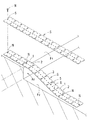
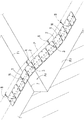
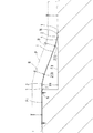
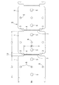
以下、最良の実施形態を挙げて、本発明を更に詳細に説明する。図1は、本発明に係る配線・配管材の支持具Sを段差部A1 に設置した状態の斜視図であり、図2は、段差部A1 に設置した支持具Sにより鞘管Pを傾斜して支持した状態の斜視図であり、図3は、同じく側面図であり、図4は、支持具Sの部分平面図であり、図5は、同じく部分側面図である。 Hereinafter, the present invention will be described in more detail with reference to the best mode. FIG. 1 is a perspective view of a state in which a support S for wiring / piping material according to the present invention is installed in a stepped portion A 1 , and FIG. 2 shows that a sheath pipe P is attached by the support S installed in the stepped portion A 1. FIG. 3 is a side view, FIG. 4 is a partial plan view of the support S, and FIG. 5 is a partial side view.
段差部A1 で鞘管Pを支持する支持具Sは、図1,図4及び図5に示されるように、細長い鋼板で形成されて、方形状をしていて、人が乗っても変形しない程度の剛性を有する剛性板部1と、該剛性板部1どうしを連結する連結板部2とが長手方向に沿って交互に形成されたものである。連結板部2は、剛性板部1と同一厚を保持したままで、幅方向の両端部に凹部3を切り込むことにより形成されている。前記凹部3は、剛性板部1に対して連結板部2の剛性を低くして部分屈曲し易くすることを主目的として、支持している鞘管Pを支持具Sに固定するための線材Bを掛止させる「線材掛止部」としても機能している。即ち、図4及び図5に示されるように、連結板部2の幅(W2 )は、剛性板部1の幅(W1 )よりも狭くなっていると共に、連結板部2の長手方向に沿った寸法(L2 )は、剛性板部1の長手方向に沿った寸法(L1 )よりも遥かに小さくなっている。また、連結板部2の表裏両面には、幅方向に沿って凹条4がそれぞれ形成されて、前記凹部3と協働して剛性板部1に対する連結板部2の剛性を低くして、その部分屈曲を容易にしている。
As shown in FIGS. 1, 4, and 5, the support tool S that supports the sheath pipe P at the stepped portion A 1 is formed of an elongated steel plate, has a rectangular shape, and is deformed even when a person gets on it. The
また、各剛性板部1には、長手方向に沿って所定間隔をおいて一対の第1釘挿通孔5が形成され、長手方向に沿って一対の第1釘挿通孔5の中間には、前記第1釘挿通孔5よりも小さな3個の第2釘挿通孔6が幅方向に沿って所定間隔をおいて形成されている。第1及び第2の各釘挿通孔5,6は、いずれも段差部A1 を形成する第1及び第2の各設置面F1 ,F2 に支持具Sを固定するための釘Nを挿通するためのものであるが、第2釘挿通孔6には、支持する鞘管Pを支持具Sに固定するためのサドル類を取付けるのに使用することもできる。実施例の支持具Sは、長さが600mm程度、幅が50mm程度、板厚が2〜2.5mmの鋼板で構成される。
Each
そして、本発明に係る支持具Sを用いて、第1及び第2の各設置面F1 ,F2 の間に形成された段差部A1 に鞘管Pを支持状態で配置するには、以下のようにして行う。まず、図1及び図3に示されるように、支持具Sにおける第1及び第2の各設置面F1 ,F2 にそれぞれ設置される部分の相前後する剛性板部1を互いに逆の方向に向けて僅かに屈曲させて、支持具Sが第1及び第2の各設置面F1 ,F2 に接線状態にして配置する。即ち、高い側の第1設置面F1 と空中部との接続部に配置される部分においては、相前後する数枚の各剛性板部1を僅かに下側に向けて部分屈曲させると共に、低い側の第2設置面F2 と空中部との接続部に配置される部分においては、相前後する数枚の各剛性板部1を上記と逆となるように、僅かに上方に向けて部分屈曲させ、空中配置された支持具Sの残りの連続する剛性板部1は、屈曲させることなく連続板状のままにしておくと、支持具Sは、これを構成する各剛性板部1が小さな角度で上記方向に部分屈曲されて、各剛性板部1の屈曲の合成により、段差部A1 においてほぼ連続曲線状となって配置される。
And, using the support tool S according to the present invention, to arrange the sheath tube P in a supported state on the stepped portion A 1 formed between the first and second installation surfaces F 1 and F 2 , This is done as follows. First, as shown in FIG. 1 and FIG. 3, the
また、段差部A1 に支持具Sを設置する際に、段差部A1 の出隅部7に連結板部2が配置されるのを避けて、特定の剛性板部1の一部が部分的に空中配置されて、残りの部分が第1設置面F1 に設置されるような片持ち状にして配置することにより、前記出隅部7の部分において支持具Sが作業者等により踏み付けられる等して、前記出隅部7において支持具Sに大きな荷重が加わっても支持具Sが屈曲されなくなる。上記のようにして、段差部A1 にほぼ連続した曲線状となって配置された支持具Sの特定の剛性板部1を第1及び第2の各設置面F1 ,F2 に釘Nを使用して固定する。即ち、特定の剛性板部1の第1釘挿通孔5に挿通された釘Nを第1及び第2の各設置面F1 ,F2 に打ち込んで固定する。図示の例では、空中配置された側から見て最初に第1及び第2の各設置面F1 ,F2 に設置された各剛性板部1と両端の各剛性板部1との4つの剛性板部1が、それぞれ各設置面F1 ,F2 に釘Nを介して固定されている。
Also, when installing the support S to the step portion A 1, to avoid the connecting
次に、図2及び図3に示されるように、段差部A1 にほぼ連続曲線状となって配置されて、第1及び第2の各設置面F1 ,F2 に固定された支持具Sによって、段差部A1 に配置される鞘管Pを支持すると共に、適宜箇所において、線材Bを使用して、鞘管Pを支持具Sに固定する。即ち、支持具Sの連結板部2に形成された凹部3に掛止された線材Bを鞘管Pに巻回して、前記線材Bの両端を結ぶと、複数本の線材Bを介して鞘管Pが長手方向に沿った複数箇所で支持具Sに固定されて、支持具Sから鞘管Pがずれ落ちなくなる。
Next, as shown in FIG. 2 and FIG. 3, a support tool that is arranged in a substantially continuous curve at the stepped portion A 1 and is fixed to the first and second installation surfaces F 1 and F 2. by S, to support the sleeve pipe P placed on the step portion a 1, in an appropriate position, using the wire B, and fixing the sheath tube P to the bracket S. That is, when the wire B hooked to the
このように、段差部A1 にほぼ連続曲線状となって配置された支持具Sによって段差部A1 に配管される鞘管Pを支持しているので、段差部A1 における鞘管Pは、大きく屈曲されることなく、支持具Sの配置形状に倣ってぼほ連続曲線状に配管される。このため、後工程において鞘管P内に線・管類を挿通する際において、段差部A1 においても線・管類は、鞘管Pの内周面に引っ掛かることなく、スムーズに挿通できる。 Thus, since the supporting sleeve pipe P to be piped to the stepped portion A 1 by support S disposed almost continuously curved step portion A 1, the sleeve pipe P at the step portion A 1 is The pipe is piped in a substantially continuous curve shape following the arrangement shape of the support S without being greatly bent. For this reason, when inserting a wire / tube into the sheath pipe P in a subsequent process, the wire / tube can be smoothly inserted into the stepped portion A 1 without being caught by the inner peripheral surface of the sheath pipe P.
また、上記実施例の支持具Sを構成する連結板部2の長手方向に沿った長さ(L2 )は、必要最小長さにしてあるので、例えば、作業中において作業者が傾斜姿勢で空中配置された部分を踏み付ける等して、空中配置される部分に大きな荷重が作用しても、変形されにくくなる。即ち、連結板部2の長手方向に沿った長さ(L2 )は、必要最小長さにしてあるために、相前後する剛性板部1の間で屈強可能な条件を満足した上で、曲げ力に対して強い構造となる。
In addition, since the length (L 2 ) along the longitudinal direction of the connecting
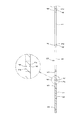
図6(イ),(ロ)は、同一の支持具Sを高さH1 ,H2 の異なる段差部A1 ,A2 にほぼ同一傾斜角度(θ)で設置した状態の模式的側面図であって、支持具Sを構成する剛性板部1を破線状にして図示してある。段差部A2 の高さH2 は、同A1 の高さH1 よりも高くて、段差部A1 と同一に配置した場合(段差部から起算して段下に当接する距離が同一である場合)には、傾斜角度が大きくなって、後工程の線・管類の挿通作業に支障をきたす恐れがある。このため、段差の大きな段差部A2 においては、図6(ロ)に示されるように、空中配置される剛性板部1の数を増して、相前後する剛性板部1の屈曲位置をずらすことにより、段差の小さな段差部A1 とほぼ同一の傾斜角度(θ)で支持具Sを配置できる。このように、同一の支持具Sによって、高さの異なる段差部に対応して、鞘管Pをほぼ連続曲線状にして支持できる。
6A and 6B are schematic side views showing a state in which the same support S is installed at substantially the same inclination angle (θ) on the stepped portions A 1 and A 2 having different heights H 1 and H 2 . The
また、図7は、設置面F3 に数本の既設管12が配管されていて、前記既設管12を跨いだ状態で鞘管Pを配管する際に、鞘管Pの空中配置部を支持具Sで支持する使用例の側面図である。この使用例においても、支持具Sの空中配置される部分の両端部が設置面F3 に対して接線状態で設置されるように、相前後する剛性板部1を僅かに屈曲させて、全体として連続曲線状にしてある。
Further, FIG. 7 shows that several existing
また、上記実施例では、支持具Sを構成する各剛性板部1に、それぞれ第1及び第2の各釘挿通孔5,6が形成されているため、支持具Sの空中配置される部分の長さとは無関係に、支持具Sの空中配置される部分に最も近い剛性板部1を設置面に固定できて、設置面に対する支持具の固定が確実となる。しかし、各剛性板部1には、例えば一個おきに第1及び第2の各釘挿通孔5,6が設けられた構成にしてもよいし、連結板部2の長手方向に沿った長さL2 を釘挿通孔を形成できる程度の寸法にして、連結板部2に釘挿通孔(支持具Sを設置面に固定するための固定部)を設けることも可能である。
Moreover, in the said Example, since each 1st and 2nd nail penetration holes 5 and 6 are each formed in each
また、支持具を設置面に固定する固定部の数に関しては、支持具の長手方向に沿って間隔をおいて複数個設ける必要がある。また、固定部の配置に関しては、支持具の長手方向の中央部は空中配置されて、設置面に設置されることは殆どないので、支持具の長手方向の中央部には、固定部を設けないか、或いは設ける場合にはその数を少なくして、設置面に必ず設置される部位である支持具の長手方向の中央部を除く部分に固定部を集中させて設けることが望ましい。 Further, regarding the number of fixing portions for fixing the support tool to the installation surface, it is necessary to provide a plurality of fixing portions at intervals along the longitudinal direction of the support tool. As for the arrangement of the fixing part, the central part in the longitudinal direction of the support tool is arranged in the air and is rarely installed on the installation surface. Therefore, the fixing part is provided in the central part in the longitudinal direction of the support tool. It is desirable that the number of the fixing portions is reduced or reduced when the fixing portions are provided, and the fixing portions are concentrated on the portion excluding the central portion in the longitudinal direction of the support, which is a portion that must be installed on the installation surface.
なお、支持具Sに対して鞘管Pを固定する線材Bを該支持具Sに対して掛止させる部分としては、前記凹部3に限られず、剛性板部1に開けられた掛止孔であってもよく、この掛止孔として第1釘挿通孔5を利用することも可能である。
In addition, as a part which latches the wire rod B which fixes the sheath pipe P with respect to the support tool S with respect to this support tool S, it is not restricted to the said recessed
A1 ,A2 :段差部
B:線材
F1 〜F3 :設置面
H1 ,H2 :段差部の高さ
P:鞘管(配線・配管材)
S:支持具
1:剛性板部
2:連結板部
3:凹部(線材掛止部)
5:第1釘挿通孔(固定部)
6:第2釘挿通孔(固定部)
A 1 , A 2 : steps
B: Wire rod
F 1 to F 3 : Installation surface
H 1 , H 2 : Height of the step
P: Sheath tube (wiring / piping material)
S: Support tool
1: Rigid plate
2: Connecting plate
3: Concave portion (wire rod retaining portion)
5: First nail insertion hole (fixed part)
6: 2nd nail insertion hole (fixed part)
Claims (5)
全体が細長い金属板で構成されて、人が乗っても変形しない程度の剛性を有する剛性板部と、該剛性板部どうしを連結する連結板部とが、長手方向に沿って交互に形成され、
各連結板部は、相前後する剛性板部を相対的に適宜角度に屈曲させるべく変形可能になっていて、前記剛性板部及び連結板部の少なくとも一方には、設置面に対する固定部が形成されていることを特徴とする配線・配管材の支持具。 A support for supporting wiring / piping material from below in a stepped part, aerial part, etc.
Rigid plate portions that are entirely composed of elongated metal plates and have rigidity sufficient to prevent deformation even when a person rides on them, and connecting plate portions that connect the rigid plate portions are alternately formed along the longitudinal direction. ,
Each connecting plate portion can be deformed so as to bend the adjacent rigid plate portions relatively at an appropriate angle, and at least one of the rigid plate portion and the connecting plate portion is formed with a fixing portion for the installation surface. A support for wiring and piping materials characterized by being made.
Priority Applications (1)
| Application Number | Priority Date | Filing Date | Title |
|---|---|---|---|
| JP2004112754A JP4619678B2 (en) | 2004-04-07 | 2004-04-07 | Wiring and piping material support |
Applications Claiming Priority (1)
| Application Number | Priority Date | Filing Date | Title |
|---|---|---|---|
| JP2004112754A JP4619678B2 (en) | 2004-04-07 | 2004-04-07 | Wiring and piping material support |
Publications (2)
| Publication Number | Publication Date |
|---|---|
| JP2005299714A true JP2005299714A (en) | 2005-10-27 |
| JP4619678B2 JP4619678B2 (en) | 2011-01-26 |
Family
ID=35331497
Family Applications (1)
| Application Number | Title | Priority Date | Filing Date |
|---|---|---|---|
| JP2004112754A Expired - Fee Related JP4619678B2 (en) | 2004-04-07 | 2004-04-07 | Wiring and piping material support |
Country Status (1)
| Country | Link |
|---|---|
| JP (1) | JP4619678B2 (en) |
Cited By (4)
| Publication number | Priority date | Publication date | Assignee | Title |
|---|---|---|---|---|
| JP2012013139A (en) * | 2010-06-30 | 2012-01-19 | Mirai Ind Co Ltd | Spacer allowing protective material for storage of wiring/piping material to pass over stepped part, structure for placing protective material for storage of wiring/piping material, and method of placing protective material for storage of wiring/piping material on mounting surface by passing over the stepped part |
| JP2012520634A (en) * | 2009-03-13 | 2012-09-06 | クゥアルコム・インコーポレイテッド | Frequency selectable multi-band (MULTI-BAND) antenna for wireless communication devices |
| JP2013005581A (en) * | 2011-06-16 | 2013-01-07 | Sumitomo Wiring Syst Ltd | Branch protector |
| JP2019190511A (en) * | 2018-04-20 | 2019-10-31 | 未来工業株式会社 | Inlet corner part protection cover, its installation structure and protection cover connection body |
Citations (3)
| Publication number | Priority date | Publication date | Assignee | Title |
|---|---|---|---|---|
| JPS60172380U (en) * | 1984-04-24 | 1985-11-15 | 沖電気工業株式会社 | Fixed structure of wiring cord |
| JPS63131516U (en) * | 1987-02-19 | 1988-08-29 | ||
| JP2004023817A (en) * | 2002-06-12 | 2004-01-22 | Kitagawa Ind Co Ltd | Cable duct |
-
2004
- 2004-04-07 JP JP2004112754A patent/JP4619678B2/en not_active Expired - Fee Related
Patent Citations (3)
| Publication number | Priority date | Publication date | Assignee | Title |
|---|---|---|---|---|
| JPS60172380U (en) * | 1984-04-24 | 1985-11-15 | 沖電気工業株式会社 | Fixed structure of wiring cord |
| JPS63131516U (en) * | 1987-02-19 | 1988-08-29 | ||
| JP2004023817A (en) * | 2002-06-12 | 2004-01-22 | Kitagawa Ind Co Ltd | Cable duct |
Cited By (6)
| Publication number | Priority date | Publication date | Assignee | Title |
|---|---|---|---|---|
| JP2012520634A (en) * | 2009-03-13 | 2012-09-06 | クゥアルコム・インコーポレイテッド | Frequency selectable multi-band (MULTI-BAND) antenna for wireless communication devices |
| EP2406849B1 (en) * | 2009-03-13 | 2017-04-19 | QUALCOMM Incorporated | Frequency selective multi-band antenna for wireless communication devices |
| JP2012013139A (en) * | 2010-06-30 | 2012-01-19 | Mirai Ind Co Ltd | Spacer allowing protective material for storage of wiring/piping material to pass over stepped part, structure for placing protective material for storage of wiring/piping material, and method of placing protective material for storage of wiring/piping material on mounting surface by passing over the stepped part |
| JP2013005581A (en) * | 2011-06-16 | 2013-01-07 | Sumitomo Wiring Syst Ltd | Branch protector |
| JP2019190511A (en) * | 2018-04-20 | 2019-10-31 | 未来工業株式会社 | Inlet corner part protection cover, its installation structure and protection cover connection body |
| JP7039379B2 (en) | 2018-04-20 | 2022-03-22 | 未来工業株式会社 | Protective cover for the inside corner, its installation structure, and protective cover connection |
Also Published As
| Publication number | Publication date |
|---|---|
| JP4619678B2 (en) | 2011-01-26 |
Similar Documents
| Publication | Publication Date | Title |
|---|---|---|
| JP2007518382A (en) | Accessories for lifting and connecting wire cable trays | |
| JP5458410B2 (en) | Vertical facing exterior structure | |
| JP5788663B2 (en) | Wire harness branching fixture | |
| US11664646B2 (en) | Flex-fitting cable tray | |
| JP2012141115A (en) | Pipe panel unit structure | |
| JP4619678B2 (en) | Wiring and piping material support | |
| KR100612468B1 (en) | Cable Tray | |
| JP6913576B2 (en) | Fixing brackets for studs | |
| JP5588799B2 (en) | Wiring / piping material drawing device and wiring / piping material drawing tool | |
| JP4182525B2 (en) | Vertical mesh rack and support member attached to the vertical mesh rack | |
| JP6196474B2 (en) | Solar panel installation structure and installation method | |
| JP7042708B2 (en) | Louver structure | |
| JP4986722B2 (en) | Cable laying cleat | |
| JP2009275418A (en) | Vertical wall panel mounting structure and base fitting | |
| JP2000035161A (en) | Wire laying structure and laying method in ship | |
| JP3163147U (en) | Steel support | |
| JP3852784B1 (en) | Reinforcing bar holding spacer and method for forming frame using the same | |
| JP4548258B2 (en) | Eaves support | |
| JP3118899U (en) | 裏 Back nut for hinge installation | |
| JP2017071930A (en) | Mounting bracket and mounting method | |
| JP4923074B2 (en) | Eaves support set | |
| JP7096997B2 (en) | bracket | |
| JP3860177B2 (en) | Plasterer | |
| JP3188054U (en) | Cable support | |
| KR100572340B1 (en) | Ceiling plate mount |
Legal Events
| Date | Code | Title | Description |
|---|---|---|---|
| A621 | Written request for application examination |
Free format text: JAPANESE INTERMEDIATE CODE: A621 Effective date: 20061116 |
|
| A977 | Report on retrieval |
Free format text: JAPANESE INTERMEDIATE CODE: A971007 Effective date: 20090630 |
|
| A131 | Notification of reasons for refusal |
Free format text: JAPANESE INTERMEDIATE CODE: A131 Effective date: 20091117 |
|
| A521 | Request for written amendment filed |
Free format text: JAPANESE INTERMEDIATE CODE: A523 Effective date: 20091217 |
|
| A131 | Notification of reasons for refusal |
Free format text: JAPANESE INTERMEDIATE CODE: A131 Effective date: 20100518 |
|
| A521 | Request for written amendment filed |
Free format text: JAPANESE INTERMEDIATE CODE: A523 Effective date: 20100616 |
|
| TRDD | Decision of grant or rejection written | ||
| A01 | Written decision to grant a patent or to grant a registration (utility model) |
Free format text: JAPANESE INTERMEDIATE CODE: A01 Effective date: 20101026 |
|
| A01 | Written decision to grant a patent or to grant a registration (utility model) |
Free format text: JAPANESE INTERMEDIATE CODE: A01 |
|
| A61 | First payment of annual fees (during grant procedure) |
Free format text: JAPANESE INTERMEDIATE CODE: A61 Effective date: 20101027 |
|
| FPAY | Renewal fee payment (event date is renewal date of database) |
Free format text: PAYMENT UNTIL: 20131105 Year of fee payment: 3 |
|
| R150 | Certificate of patent or registration of utility model |
Ref document number: 4619678 Country of ref document: JP Free format text: JAPANESE INTERMEDIATE CODE: R150 Free format text: JAPANESE INTERMEDIATE CODE: R150 |
|
| FPAY | Renewal fee payment (event date is renewal date of database) |
Free format text: PAYMENT UNTIL: 20131105 Year of fee payment: 3 |
|
| R250 | Receipt of annual fees |
Free format text: JAPANESE INTERMEDIATE CODE: R250 |
|
| R250 | Receipt of annual fees |
Free format text: JAPANESE INTERMEDIATE CODE: R250 |
|
| R250 | Receipt of annual fees |
Free format text: JAPANESE INTERMEDIATE CODE: R250 |
|
| R250 | Receipt of annual fees |
Free format text: JAPANESE INTERMEDIATE CODE: R250 |
|
| R250 | Receipt of annual fees |
Free format text: JAPANESE INTERMEDIATE CODE: R250 |
|
| R250 | Receipt of annual fees |
Free format text: JAPANESE INTERMEDIATE CODE: R250 |
|
| R250 | Receipt of annual fees |
Free format text: JAPANESE INTERMEDIATE CODE: R250 |
|
| R250 | Receipt of annual fees |
Free format text: JAPANESE INTERMEDIATE CODE: R250 |
|
| LAPS | Cancellation because of no payment of annual fees |