JP2005299680A - Axial turbine blade - Google Patents
Axial turbine blade Download PDFInfo
- Publication number
- JP2005299680A JP2005299680A JP2005202157A JP2005202157A JP2005299680A JP 2005299680 A JP2005299680 A JP 2005299680A JP 2005202157 A JP2005202157 A JP 2005202157A JP 2005202157 A JP2005202157 A JP 2005202157A JP 2005299680 A JP2005299680 A JP 2005299680A
- Authority
- JP
- Japan
- Prior art keywords
- blade
- flow
- peripheral wall
- axial
- turbine
- Prior art date
- Legal status (The legal status is an assumption and is not a legal conclusion. Google has not performed a legal analysis and makes no representation as to the accuracy of the status listed.)
- Withdrawn
Links
Images

Landscapes
- Turbine Rotor Nozzle Sealing (AREA)
Abstract
【課題】吹き出しに使用できる高圧流体の流量に制限がある場合に効果的に流れ損失の低減を図ることができる軸流タービン翼の提供。
【解決手段】軸流タービンの静翼1または動翼2であって、翼の内部に中空部7を形成するとともに、翼の後縁部に中空部に連通する吹き出し口を形成し、翼後縁まわりの作動流体流路に流れる主流作動流体よりも高圧で前記中空部に導かれた流体を、翼後縁側の吹き出し口から作動流体流路に吹き出すようにした軸流タービンにおいて、吹き出し口は、内周壁側に外周壁側よりも多量の吹き出し流体が流れるように形成される。
【選択図】 図1An axial flow turbine blade capable of effectively reducing a flow loss when a flow rate of a high-pressure fluid that can be used for blowing is limited.
A stationary blade 1 or a moving blade 2 of an axial-flow turbine, in which a hollow portion 7 is formed inside the blade, and a blowout port communicating with the hollow portion is formed in a rear edge portion of the blade. In the axial flow turbine in which the fluid guided to the hollow portion at a pressure higher than that of the main flow working fluid flowing in the working fluid flow path around the edge is blown out from the blowout opening on the blade trailing edge side to the working fluid flow path, The inner peripheral wall side is formed such that a larger amount of blowing fluid flows than the outer peripheral wall side.
[Selection] Figure 1
Description
本発明は軸流タービンの静翼または動翼の改良に係り、特に翼の加熱、冷却、流れの制御の目的で翼の内部に流体を導いて翼後縁又は翼表面から吹き出すようにしたものにおいて、流れの適正化のための吹き出し口部の形状を改良した軸流タービン翼に関する。 The present invention relates to an improvement of a stationary blade or a moving blade of an axial flow turbine, and in particular, for the purpose of heating, cooling, and flow control of a blade, a fluid is introduced into the blade and blown out from the blade trailing edge or the blade surface. The present invention relates to an axial-flow turbine blade having an improved shape of a blow-out port portion for flow optimization.
軸流タービン翼の内部に中空部を形成して、翼まわりを流れる主流作動流体より高圧の流体を翼内部に導いて、後縁や翼表面から流出させるようにしたタービン翼は、タービンの性能と信頼性を向上させるために、ガスタービンでは一般的に使用されており、また蒸気タービンに適用する構成例も既に提案されている。 A turbine blade that has a hollow part inside the axial flow turbine blades and guides a fluid higher in pressure than the mainstream working fluid that flows around the blades to the inside of the blades and outflows from the trailing edge or blade surface. In order to improve the reliability, the gas turbine is generally used, and a configuration example applied to the steam turbine has already been proposed.
ガスタービンにおいては、タービン翼を冷却するためにタービンの作動流体より低温高圧の空気を圧縮機から抽気して、タービン段落の静翼及び動翼の内部の中空部に導き、翼後縁や翼表面から吹き出している。 In a gas turbine, in order to cool the turbine blades, air at a temperature lower than that of the turbine working fluid is extracted from the compressor and guided to the hollow portions inside the stationary blades and the moving blades of the turbine stage. It is blowing out from the surface.
一方、蒸気タービンに関しては、湿り蒸気中で使用されるタービン静翼内部に高温高圧の蒸気を導いて静翼を加熱して表面を流れる凝縮水分を再度蒸発させ、下流動翼の水分による浸食を防止し、さらに水滴の衝突によって生じる損失を低減するための技術が特開昭50−112604号公報などで提案されている。 On the other hand, with regard to steam turbines, high-temperature and high-pressure steam is introduced into the turbine vanes used in wet steam to heat the vanes to re-evaporate the condensed water flowing on the surface, and the lower flow blades are eroded by moisture. Japanese Laid-Open Patent Publication No. 50-112604 proposes a technique for preventing and further reducing the loss caused by the collision of water droplets.
更に、一般の軸流流体機械の段落の二次流れ損失と後流損失の低減を目的として、翼表面から主流の一部を吸い込んで翼内部に導き、後縁から吹き出させる構造が特公昭56−14845号公報で提案されている。 Further, for the purpose of reducing the secondary flow loss and the wake loss in the paragraph of a general axial flow fluid machine, a structure in which a part of the main flow is sucked from the blade surface and guided to the inside of the blade and blown out from the trailing edge is disclosed in JP-B-56. This is proposed in Japanese Patent No. 14845.
以上の従来技術の中から特開昭50−112604号公報に記載された蒸気タービンに関する技術を例にして具体的に説明する。 Of the above conventional techniques, a technique related to the steam turbine described in Japanese Patent Application Laid-Open No. 50-112604 will be specifically described.
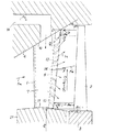
図6および図7は、前述した蒸気タービンの例の一つで、低圧最終段への適用例である。タービンの段落は周方向に複数枚配置された静翼1と、同じく周方向に複数枚配置された動翼2とによって構成される。動翼2はロータ3に植え込まれており、ロータ3と共に回転する。
6 and 7 are examples of the steam turbine described above, and are examples of application to the low-pressure final stage. The paragraph of the turbine is composed of a plurality of
静翼2はケーシング4に固定されており、ケーシング4の通路側表面は、静翼1に流通する主流作動流体Fmを外側から囲む外周壁11を形成しており、静翼2の内輪側植え込み部の表面は内周壁11を形成している。最終段の上流段落の静翼入口部には高温高圧の作動流体の吸い込み口5が設けてあり、この吸い込み口5から取り入れた蒸気はバイパス通路6を通って静翼1の内部の中空部7に導かれる。
The
図7は図6のA−A断面図である。静翼1の後縁には吹き出し口としての後縁吹き出し口9が形成されており、中空部7の蒸気は吹き出し通路8によって後縁吹き出し口9に導かれる。
7 is a cross-sectional view taken along the line AA in FIG. A trailing edge outlet 9 as an outlet is formed at the rear edge of the
以上のように構成した蒸気タービンにおいては、吸い込み口5から最終段に比べて高温高圧で、通常は乾き状態の蒸気を取り入れ、バイパス通路6を通して中空部7に導くようになっている。静翼1はこの蒸気によって加熱され、表面を流れる凝縮水分の一部は再度蒸発して蒸気になる。
In the steam turbine configured as described above, steam which is normally dry at a higher temperature and pressure than the last stage is taken in from the
中空部7の蒸気は、吹き出し通路8を通って後縁吹き出し口9から主流蒸気中に吹き出される。このとき、静翼1の加熱によって蒸発せずに後縁まで到達した水分が吹き飛ばされて微細化する。この結果、動翼2に衝突する水分の合計量と浸食作用の強い比較的大きな水滴の数の両方が減少して動翼2の浸食が低減され、合わせて水滴の動翼2への衝突によって生ずる段落性能の低下も低減される。
The steam in the
この従来技術においては、後縁吹き出し口9からの噴射の方向は作動流体の流出方向とほぼ一致させ、また噴射速度は作動流体の主流の速度に等しいか、もしくはそれより若干高めとなるようにされている。
上記のように構成された蒸気タービンは、静翼上の凝縮水分を静翼表面から吸い込んで外部に排出してしまう方法に比べて、蒸気の一部が水分と一緒に外部に流出してしまうことが無いので、段落の性能を損なうことがなく、動翼の浸食を防止できて望ましいように思われる。そこで、環状翼列試験によって後縁からの吹き出しが段落性能に及ぼす影響を調べたところ、以下の問題点が明らかになった。 The steam turbine configured as described above causes a part of the steam to flow out together with moisture compared to a method in which condensed moisture on the stationary blade is sucked from the surface of the stationary blade and discharged to the outside. This seems to be desirable because it does not impair the performance of the paragraph and prevents erosion of the rotor blades. Therefore, the influence of blowout from the trailing edge on the paragraph performance was examined by the annular cascade test, and the following problems were clarified.
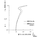
図8は静翼の損失分布を全圧損失係数で表したものである。縦軸は後縁高さで無次元化した静翼出口の高さ位置を表し、横軸は吹き出しなしの時の流路中央の全圧損失係数ζPCDで無次元化した全圧損失係数を表している。実線は後縁吹き出しが無い場合、破線は後縁吹き出しが有る場合の計測値を示す。 FIG. 8 shows the loss distribution of the stationary blade in terms of the total pressure loss coefficient. The vertical axis represents the height position of the stationary blade outlet made dimensionless with the trailing edge height, and the horizontal axis represents the total pressure loss coefficient made dimensionless with the total pressure loss coefficient ζPCD at the center of the flow path when there is no blowing. ing. A solid line indicates a measured value when there is no trailing edge balloon, and a broken line indicates a measured value when there is a trailing edge balloon.
無次元高さ0.8以上で損失が急に増加するのは、外周壁面10の低エネルギー流体が主流に流れ込んで生ずる二次流れによる。この部分では、後縁吹き出し有りの時の損失が吹き出しなしを上回っている。
The sudden increase in loss at a dimensionless height of 0.8 or more is due to the secondary flow generated by the low energy fluid on the outer
一方、無次元高さ0.5から0.7ではわずかに吹き出し有りの損失が減少している。従って、外周壁側の高さ0.8から1.0の間で吹き出しを行った場合は吹き出しによる効率の低下が大きく、高さ0.5から1.0の間で吹き出しを行った場合には中央付近の損失減少により多少改善されるが、やはり効率は低下する。 On the other hand, when the dimensionless height is 0.5 to 0.7, the loss with blowing is slightly reduced. Therefore, when blowing is performed at a height between 0.8 and 1.0 on the outer peripheral wall side, the reduction in efficiency due to the blowing is large, and when blowing is performed at a height between 0.5 and 1.0. Is somewhat improved by reducing the loss near the center, but efficiency is still reduced.
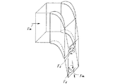
図9は翼列下流の二次流れを簡略化して表現した説明図である。外周壁及び内周壁上の境界層を形成する速度の遅い低エネルギーの流れの部分が、翼列流路の腹側から背側への圧力勾配によって翼背側に移動する。背側に到達した低エネルギー流体は更に背側の一定の高さの位置まで入り込んで行き、ここで翼面から離れて渦を形成して行く。 FIG. 9 is an explanatory diagram showing a simplified secondary flow downstream of the blade row. The portion of the low-energy flow that forms a boundary layer on the outer peripheral wall and the inner peripheral wall moves to the blade back side due to the pressure gradient from the ventral side to the back side of the cascade passage. The low-energy fluid that has reached the dorsal side further enters a position at a certain height on the dorsal side, where it forms a vortex away from the wing surface.
従って、二次流れの影響領域においては、後縁に沿って流路中央に向かう速度成分が存在することがわかる。ここに後縁からの吹き出しを行うと、吹き出された流体は二次流れ渦に引き込まれて同じ方向に偏向し、その結果二次流れ渦にエネルギーを供給して二次流れ損失を増加させると考えられる。 Therefore, it can be seen that there is a velocity component toward the center of the flow path along the trailing edge in the influence region of the secondary flow. When blowing from the trailing edge here, the blown fluid is drawn into the secondary flow vortex and deflected in the same direction, and as a result, energy is supplied to the secondary flow vortex to increase the secondary flow loss. Conceivable.
図6、図7で説明した従来技術の例では、吹き出しの周方向の角度は比較的長い助走区間として吹き出し通路8を設けることにより、作動流体の主流の方向に向けることができるが、後縁に沿った流れの方向はなんら拘束できず、その結果吹き出し通路8の入口と出口の状態で流れの方向が決定してしまうことになる。
In the example of the prior art described in FIGS. 6 and 7, the circumferential angle of the blowout can be directed in the direction of the main flow of the working fluid by providing the
図6の中空部7の構造から明らかなように、中空部には外周壁から流路中央に向かう流れが生じており、前述した二次流れの方向に吹き出す傾向を助長していることがわかる。二次流れの影響があまり及ばない流路中央付近で吹き出しによって損失が低減される現象を明らかにするために高精度の流れの数値シミュレーションを実施したところ、吹き出しの無い後縁において通常生じている逆流領域が吹き出し流れで満たされており、逆流による乱れのない安定した流れになっていることが分かった。
As is clear from the structure of the
従って、二次元的な流れとなっている流路中央では、吹き出しは翼列の損失を低減するが、流れの3次元性が著しい内外壁の近くでは何らかの方法で吹き出しの半径方向の流れの向きを制御しない限り、吹き出しは二次流れを増大させる方向に作用し、段落全体で見た場合タービンの効率を低下させることになる。 Therefore, in the center of the flow path, which is a two-dimensional flow, the blowout reduces the blade loss, but in some way near the inner and outer walls where the flow has a significant three-dimensionality, the flow direction of the blowout in the radial direction is somehow. Unless the air pressure is controlled, the blowout acts in the direction of increasing the secondary flow, and the efficiency of the turbine is reduced when viewed in the whole paragraph.
他の従来技術についても同様な問題点がある。特公昭56−14845号においても後縁に沿った方向の吹き出しの制御は何等なされておらず、そのかわりに二次流れの低減対策として周方向の吹き出し流出角度を幾何学的な静翼流出角から3〜5度オフセットすることを提案している。 Other conventional techniques have similar problems. Japanese Patent Publication No. 56-14845 does not control the blowout in the direction along the trailing edge. Instead, as a measure for reducing the secondary flow, the circumferential blowout outflow angle is changed to the geometric stationary blade outflow angle. 3 to 5 degrees offset from
しかしながら、翼列の流出角度は流出速度などの流体条件で変化し、更に主流の方向と後縁のすぐ下流の後流内では1度以上の差が有るので効果的なオフセット角度を見つけることは事実上かなり難しく、効果の程度も十分ではないと考えられる。 However, since the blade outflow angle varies with fluid conditions such as outflow velocity, and there is a difference of more than 1 degree in the main flow direction and in the wake just downstream of the trailing edge, finding an effective offset angle is not possible. It is actually quite difficult and the degree of effect is not considered sufficient.
ガスタービン冷却翼に関しては非常に多くの提案がなされている。たとえば、特開平6−137105号では、後縁の外周壁と内周壁の近くで吹き出しスリットの開口面積を大きくして、二次流れ損失を低減させる技術が開示されている。しかしながら、開口面積を大きく取るだけで流出方向を効果的に制御しなければ、前述した例のようにかえって二次流れを増大させることになる。 Many proposals have been made regarding gas turbine cooling blades. For example, Japanese Patent Laid-Open No. 6-137105 discloses a technique for reducing the secondary flow loss by increasing the opening area of the blow slit near the outer peripheral wall and the inner peripheral wall of the trailing edge. However, if the outflow direction is not controlled effectively only by taking a large opening area, the secondary flow is increased instead of the example described above.
本発明は上述した事情を考慮してなされたもので、吹き出しに使用できる高圧流体の流量に制限がある場合に効果的に流れ損失の低減を図ることができる軸流タービン翼を提供することを目的とする。また、翼後縁や翼表面からの高圧流体の吹き出しによって損失が増加せず、むしろ吹き出しによって効率が向上するように機能する軸流タービン翼を提供することを目的とする。 The present invention has been made in consideration of the above-described circumstances, and provides an axial flow turbine blade capable of effectively reducing flow loss when the flow rate of a high-pressure fluid that can be used for blowing is limited. Objective. It is another object of the present invention to provide an axial-flow turbine blade that functions so that the loss does not increase by blowing out high-pressure fluid from the blade trailing edge or the blade surface, but rather the efficiency is improved by blowing.
上述した課題を解決するために、請求項1の発明は、軸流タービンの静翼または動翼であって、翼の内部に中空部を形成するとともに、翼の後縁部に前記中空部に連通する吹き出し口を形成し、翼後縁まわりの作動流体流路に流れる主流作動流体よりも高圧で前記中空部に導かれた流体を、前記翼後縁側の吹き出し口から前記作動流体流路に吹き出すようにした軸流タービンにおいて、前記吹き出し口は、内周壁側に外周壁側よりも多量の吹き出し流体が流れるように形成されていることを特徴とする。
In order to solve the above-described problem, the invention of
請求項2の発明は、請求項1に記載の軸流タービン翼において、前記吹き出し口は、前記内周壁近くの後縁部のみに設けられていることを特徴とする。 According to a second aspect of the present invention, in the axial turbine blade according to the first aspect, the outlet is provided only at a rear edge near the inner peripheral wall.
請求項3の発明は、請求項1に記載の軸流タービン翼において、前記吹き出し口は、内周壁近くの開口部幅が外周壁近くの吹き出し口の開口部幅に比べて大きく形成されていることを特徴とする。 According to a third aspect of the present invention, in the axial-flow turbine blade according to the first aspect, the blower outlet is formed such that the opening width near the inner peripheral wall is larger than the opening width of the blower outlet near the outer peripheral wall. It is characterized by that.
なお、本発明においては、翼内部の中空部に導かれた高圧流体は後縁から吹き出される際に、内周壁近くでは内周壁側に傾斜するように吹き出す構成とすることが望ましい。このような構成とすることにより、図8に示した二次流れFsと逆向きの流れが後縁下流に生じて二次流れの渦を弱くし、二次流れ損失を低減させることができる。 In the present invention, it is desirable that the high-pressure fluid guided to the hollow portion inside the blade is blown so as to be inclined toward the inner peripheral wall near the inner peripheral wall when blown out from the trailing edge. By adopting such a configuration, a flow in the direction opposite to the secondary flow Fs shown in FIG. 8 is generated downstream of the trailing edge, weakening the vortex of the secondary flow, and reducing the secondary flow loss.
本発明に係る軸流タービン翼によれば、一般的に二次流れ損失と衝撃波損失が大きい内周壁側に集中して吹き出しを行うことにより、吹き出しに使用できる高圧流体の流量に制限がある場合に効果的に流れ損失の低減を図ることができる。 According to the axial turbine blade according to the present invention, there is a restriction on the flow rate of the high-pressure fluid that can be used for blowing by concentrating on the inner peripheral wall side where the secondary flow loss and the shock wave loss are generally large. Therefore, the flow loss can be effectively reduced.
また、本発明において、翼内部の中空部に導かれた高圧流体は後縁から吹き出される際に、内周壁近くでは内周壁側に傾斜するように吹き出す構成とすれば、翼列の二次流れと反対方向の吹き出し流れを生じさせることができ、それによって二次流れの渦を減衰させることができる。従って、後縁からの吹き出しによっては損失が増加せず、むしろ吹き出しによって効率が向上する等の効果が奏される。すなわち、二次流れと逆向きの流れが後縁下流に生じて二次流れの渦を弱くし、二次流れ損失を低減させることができる。 Further, in the present invention, when the high-pressure fluid guided to the hollow portion inside the blade is blown from the trailing edge, it is blown so as to be inclined toward the inner peripheral wall near the inner peripheral wall. A blow-out flow in the opposite direction to the flow can be generated, thereby attenuating the secondary flow vortex. Therefore, the loss does not increase due to the blowout from the trailing edge, but rather the effect of improving the efficiency by the blowout is achieved. That is, a flow opposite to the secondary flow is generated downstream of the trailing edge to weaken the vortex of the secondary flow and reduce the secondary flow loss.
以下、本発明の実施形態を図面に基づいて説明する。 Hereinafter, embodiments of the present invention will be described with reference to the drawings.
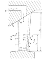
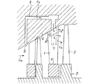
図1および図2は軸流タービンの一実施形態を示している。なお、従来の構成と同一または対応する部分には図6および図7と同一の符号を用いて説明する。 1 and 2 show an embodiment of an axial flow turbine. Parts that are the same as or correspond to those in the conventional configuration will be described using the same reference numerals as in FIGS.
本実施形態では、図1および図2に示すように、作動流体流路の外周壁10を構成するケーシング4と内周壁11を構成する静翼内輪21との間に、周方向に数十枚の静翼1が接合固定されている。また、ロータ3には周方向に数十枚の動翼2(図5参照)が取り付けられ、高速で回転できる構成になっている。
In this embodiment, as shown in FIG. 1 and FIG. 2, dozens of sheets in the circumferential direction between the
ケーシング4には高圧流体通路16が設けられており、図示しない上流のタ一ビン段落や外部の圧縮機などから、翼の加熱、冷却あるいは流れの制御等の目的で高圧流体が静翼1の内部の中空部に導かれるようになっている。なお、本実施形態は静翼を対象として説明しているが、動翼を対象とする場合には、高圧流体通路16がロータ3の内部に設けられる。
The
本実施形態においては、後縁部の吹き出し通路8が静翼1の内周壁11に近い部分だけに設けられており、高圧流体はもっぱら静翼1の内周壁11側の近くに壁の方向に向かって吹き出すようになっている。すなわち、内周壁11の壁際で、後縁全長の5%から10%の長さの位置までには後縁吹き出し口9を設けず、吹き出し通路内周側壁15を設け、内周壁11から遠い部分には吹き出し通路外周側壁12を設けている。
In the present embodiment, the
図2は図1のB−B断面図であり、この図2に示すように、中空部7と後縁吹き出し口9の間には、吹き出し通路8が設けられている。そして図1に示すように、吹き出し通路8は案内翼13によって仕切られ、各半径ごとにあらかじめ決められた子午面傾斜角βで、高圧流体が後縁から吹き出すようになっている。
FIG. 2 is a cross-sectional view taken along the line B-B in FIG. 1. As shown in FIG. 2, a
タービン中心軸から計った外周壁の傾斜角をβt、外周壁と後縁の交点の半径をRt、内周壁の傾斜角をβr、内周壁と後縁の交点の半径をRrとし、任意半径Rにおける後縁位置で定義した平均傾斜角βmを、
[数1]
βm={βt(R−Rr)+βr(Rt−R)}/(Rt−Rr)
と定義した場合、後縁吹き出しの子午面傾斜角βが、
[数2]
R<(Rr+Rt)/2においてはβ<βm,
R>(Rr+Rt)/2においてはβ>βm
となるように、後縁吹き出し口9を形成する案内翼13の形状と半径方向の取り付け角度を調整している。
The inclination angle of the outer peripheral wall measured from the turbine central axis is βt, the radius of the intersection of the outer peripheral wall and the rear edge is Rt, the inclination angle of the inner peripheral wall is βr, the radius of the intersection of the inner peripheral wall and the rear edge is Rr, and an arbitrary radius R The average inclination angle βm defined by the trailing edge position at
[Equation 1]
βm = {βt (R−Rr) + βr (Rt−R)} / (Rt−Rr)
The meridian inclination angle β of the trailing edge balloon is
[Equation 2]
For R <(Rr + Rt) / 2, β <βm,
For R> (Rr + Rt) / 2, β> βm
Thus, the shape of the
次に、本実施形態の作用について説明する。高圧流体の流れFhは、中空部7から吹き出し通路8を通って後縁吹き出し口9から主流作動流体Fmに吹き出す間に、吹き出し通路8の中に設けられた案内翼13、吹き出し通路外周側壁12、吹き出し通路内周側壁15によって、流路中央より内周壁寄りでは内周壁11の方向に向かう速度成分を与えられる。一方、外周壁10に近い位置には吹き出し口が開口していないので、壁の近くで吹き出した流体同士が衝突することがなく滑らかに流れる。
Next, the operation of this embodiment will be described. While the flow Fh of the high-pressure fluid is blown out from the
このように本実施形態によれば、後縁からの吹き出しの方向を後縁に沿って内周壁11の方向に傾斜させることができ、しかも壁の極めて近い位置に過度の集中をすることがないので、効果的に二次流れを抑制してタービン段落の損失を低減することができる。 Thus, according to this embodiment, the direction of the blow-out from the rear edge can be inclined toward the inner peripheral wall 11 along the rear edge, and there is no excessive concentration at a position very close to the wall. Therefore, it is possible to effectively suppress the secondary flow and reduce the turbine stage loss.
翼を周方向に傾斜させたり、湾曲させる従来の二次流れの抑制手段では、周方向に平均的な効果しか期待できないのに対し、本実施形態では二次流れの渦が集中する後流付近に、集中的に二次流れの渦と逆方向の流れを起こすものであり、より効果的に渦を減衰させることができる。 The conventional secondary flow suppression means that inclines or curves the blade in the circumferential direction can only expect an average effect in the circumferential direction, but in this embodiment, the vicinity of the wake where the secondary flow vortices concentrate In addition, the flow in the opposite direction to the vortex of the secondary flow is caused intensively, and the vortex can be attenuated more effectively.
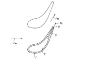
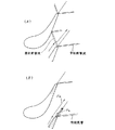
本実施形態によれば、特に主流作動流体Fmが遷音流れになっており、高圧流体Fhの流量に制約が有る場合に効果的である。例えば、圧縮機からの高圧流体で静翼1を冷却する場合を考えると、通常冷却に必要な高圧の空気流量は主流作動流体の質量流量の2%前後である。一方、主流が遷音速になると、翼列の損失が急に大きくなる。これは、図8(A)に示すように、静翼後縁の背側と腹側に衝撃波が発生して、特に、腹側の衝撃波が隣接翼の背側に入射し、この部分の境界層を乱すことに起因する。ここで後縁から主流の4%前後の吹き出しを行うと、図3(B)に示すように、腹側の衝撃波が消滅することが分かっている。
According to this embodiment, the mainstream working fluid Fm is a transonic flow, which is effective when the flow rate of the high-pressure fluid Fh is limited. For example, considering the case where the
また、通常の設計をした翼列では流速が上がるに従って内輪側から衝撃波の発生する条件になって行く。従って冷却空気量を増やさずにタービン段落の損失の低減を図るためには、内輪側に吹き出しを集中することが効果的である。 Moreover, in a normal cascade, the conditions for generating a shock wave from the inner ring side are increased as the flow velocity increases. Therefore, in order to reduce the loss of the turbine stage without increasing the amount of cooling air, it is effective to concentrate the blowouts on the inner ring side.
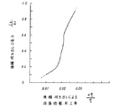
図4は後縁吹き出し口を内輪側から徐々に長くしたときの段落性能向上率の変化を示す。後縁吹き出し口の長さが0.5すなわち、静翼後縁高さの中央から内輪側の半分だけ吹き出しを行うことによって、後縁全長にて吹き出しを行ったときの約2/3の効果を上げている。冷却空気流量には圧縮機側の制約で性能を落とさずに供給できる限界があるので、本発明が有効となる。 FIG. 4 shows the change in the paragraph performance improvement rate when the trailing edge outlet is gradually lengthened from the inner ring side. The length of the trailing edge blowout port is 0.5, that is, about 2/3 of the effect of blowing out the entire trailing edge by blowing out only half the inner ring side from the center of the trailing blade rear edge height. Is raised. Since the cooling air flow rate has a limit that can be supplied without degrading performance due to restrictions on the compressor side, the present invention is effective.
なお、以上の一実施形態では、後縁吹き出し口9が内周壁11近くの後縁部のみに設けられている構成としたが、これに限らず、図5に示すように、後縁吹き出し口9を外周壁10近くの後縁部にも設けた構成とし、その場合において後縁吹き出し口9は内周壁10近くの開口部幅が外周壁近くの吹き出し口の開口部幅に比べて大きく形成されているものとしてもよい。このような構成であっても、上記同様の作用効果が奏される。
In the above embodiment, the rear edge outlet 9 is provided only at the rear edge near the inner peripheral wall 11. However, the present invention is not limited thereto, and as shown in FIG. 9 is also provided at the rear edge near the outer
1 静翼
2 動翼
3 ロータ
4 ケーシング
5 吸い込み口
6 バイパス通路
7 中空部
8 吹き出し通路
9 後縁吹き出し口
10 外周壁
11 内周壁
12 通路外周側壁
13 案内翼
15 吹き出し通路内周側壁
16 高圧流体通路
17 流体入口
21 静翼内輪
DESCRIPTION OF
Claims (3)
Priority Applications (1)
| Application Number | Priority Date | Filing Date | Title |
|---|---|---|---|
| JP2005202157A JP2005299680A (en) | 2005-07-11 | 2005-07-11 | Axial turbine blade |
Applications Claiming Priority (1)
| Application Number | Priority Date | Filing Date | Title |
|---|---|---|---|
| JP2005202157A JP2005299680A (en) | 2005-07-11 | 2005-07-11 | Axial turbine blade |
Related Parent Applications (1)
| Application Number | Title | Priority Date | Filing Date |
|---|---|---|---|
| JP00771896A Division JP3786458B2 (en) | 1996-01-19 | 1996-01-19 | Axial turbine blade |
Publications (1)
| Publication Number | Publication Date |
|---|---|
| JP2005299680A true JP2005299680A (en) | 2005-10-27 |
Family
ID=35331470
Family Applications (1)
| Application Number | Title | Priority Date | Filing Date |
|---|---|---|---|
| JP2005202157A Withdrawn JP2005299680A (en) | 2005-07-11 | 2005-07-11 | Axial turbine blade |
Country Status (1)
| Country | Link |
|---|---|
| JP (1) | JP2005299680A (en) |
Cited By (4)
| Publication number | Priority date | Publication date | Assignee | Title |
|---|---|---|---|---|
| JP2015001228A (en) * | 2013-06-17 | 2015-01-05 | アルストム テクノロジー リミテッドALSTOM Technology Ltd | Control of low volumetric flow instability in steam turbines |
| JP2017053287A (en) * | 2015-09-10 | 2017-03-16 | 新日本造機株式会社 | Steam turbine |
| EP3591175A1 (en) * | 2018-07-02 | 2020-01-08 | Siemens Aktiengesellschaft | Exhaust outlet of a steam turbine |
| US11492920B2 (en) | 2017-02-10 | 2022-11-08 | Mitsubishi Heavy Industries, Ltd. | Steam turbine |
-
2005
- 2005-07-11 JP JP2005202157A patent/JP2005299680A/en not_active Withdrawn
Cited By (4)
| Publication number | Priority date | Publication date | Assignee | Title |
|---|---|---|---|---|
| JP2015001228A (en) * | 2013-06-17 | 2015-01-05 | アルストム テクノロジー リミテッドALSTOM Technology Ltd | Control of low volumetric flow instability in steam turbines |
| JP2017053287A (en) * | 2015-09-10 | 2017-03-16 | 新日本造機株式会社 | Steam turbine |
| US11492920B2 (en) | 2017-02-10 | 2022-11-08 | Mitsubishi Heavy Industries, Ltd. | Steam turbine |
| EP3591175A1 (en) * | 2018-07-02 | 2020-01-08 | Siemens Aktiengesellschaft | Exhaust outlet of a steam turbine |
Similar Documents
| Publication | Publication Date | Title |
|---|---|---|
| US8202039B2 (en) | Blade shroud with aperture | |
| JP3786458B2 (en) | Axial turbine blade | |
| JP5383270B2 (en) | Gas turbine blade | |
| JP4993726B2 (en) | Cascade tip baffle airfoil | |
| JP6073351B2 (en) | Gas turbine blade with tip and cooling channel offset toward the pressure side | |
| US5797726A (en) | Turbulator configuration for cooling passages or rotor blade in a gas turbine engine | |
| CN101563526B (en) | Diffuser and exhaust system for turbine | |
| JP4184323B2 (en) | Hollow rotor blades for gas turbine engine turbines | |
| US9896942B2 (en) | Cooled turbine guide vane or blade for a turbomachine | |
| KR101596068B1 (en) | Hollow turbine wheel vane comprising a rib and associated wheel and turbomachine | |
| EP2896787B1 (en) | Gas turbine | |
| EP2148042A2 (en) | A blade for a rotor having a squealer tip with a partly inclined surface | |
| US10082031B2 (en) | Rotor of a turbine of a gas turbine with improved cooling air routing | |
| WO2007052337A1 (en) | Turbine part | |
| CN101666244A (en) | Turbine bucket for a turbomachine and method of reducing bow wave effects at a turbine bucket | |
| KR102492725B1 (en) | Impingement insert for re-using impingement air in an airfoil, airfoil comprising an Impingement insert, turbomachine component and a gas turbine having the same | |
| EP2518269B1 (en) | Stator vane assembly for a gas turbine | |
| RU2670650C9 (en) | Turbine blade | |
| US11708762B2 (en) | Film cooling structure and turbine blade for gas turbine engine | |
| EP3483395B1 (en) | Inter-turbine ducts with flow control mechanisms | |
| KR20220040981A (en) | A technique for cooling squealer tip of a gas turbine blade | |
| US10041352B2 (en) | Stator of a turbine of a gas turbine with improved cooling air routing | |
| JP2005299680A (en) | Axial turbine blade | |
| JP4184565B2 (en) | Steam turbine nozzle and steam turbine using the steam turbine nozzle | |
| EP3981953B1 (en) | Film cooling structure and turbine blade for gas turbine engine |
Legal Events
| Date | Code | Title | Description |
|---|---|---|---|
| A131 | Notification of reasons for refusal |
Free format text: JAPANESE INTERMEDIATE CODE: A131 Effective date: 20051122 |
|
| A761 | Written withdrawal of application |
Free format text: JAPANESE INTERMEDIATE CODE: A761 Effective date: 20060124 |