JP2005299675A - Internal combustion engine starting/stopping device - Google Patents
Internal combustion engine starting/stopping device Download PDFInfo
- Publication number
- JP2005299675A JP2005299675A JP2005154958A JP2005154958A JP2005299675A JP 2005299675 A JP2005299675 A JP 2005299675A JP 2005154958 A JP2005154958 A JP 2005154958A JP 2005154958 A JP2005154958 A JP 2005154958A JP 2005299675 A JP2005299675 A JP 2005299675A
- Authority
- JP
- Japan
- Prior art keywords
- engine
- starter
- spring
- rotatable
- elastic member
- Prior art date
- Legal status (The legal status is an assumption and is not a legal conclusion. Google has not performed a legal analysis and makes no representation as to the accuracy of the status listed.)
- Withdrawn
Links
- 238000002485 combustion reaction Methods 0.000 title claims abstract description 23
- 230000007246 mechanism Effects 0.000 claims abstract description 39
- 239000007858 starting material Substances 0.000 claims description 131
- 238000004146 energy storage Methods 0.000 claims description 12
- 230000004044 response Effects 0.000 claims description 5
- 230000005540 biological transmission Effects 0.000 description 16
- 238000004804 winding Methods 0.000 description 12
- 210000000078 claw Anatomy 0.000 description 9
- 241000282472 Canis lupus familiaris Species 0.000 description 8
- 230000008901 benefit Effects 0.000 description 6
- 230000002093 peripheral effect Effects 0.000 description 5
- 239000000463 material Substances 0.000 description 4
- 239000002184 metal Substances 0.000 description 4
- 230000000903 blocking effect Effects 0.000 description 3
- 230000033001 locomotion Effects 0.000 description 3
- 230000009471 action Effects 0.000 description 2
- 230000003213 activating effect Effects 0.000 description 2
- 230000006835 compression Effects 0.000 description 2
- 238000007906 compression Methods 0.000 description 2
- 239000004020 conductor Substances 0.000 description 2
- 238000010276 construction Methods 0.000 description 2
- 238000000034 method Methods 0.000 description 2
- 230000004048 modification Effects 0.000 description 2
- 238000012986 modification Methods 0.000 description 2
- 230000036961 partial effect Effects 0.000 description 2
- 229920002994 synthetic fiber Polymers 0.000 description 2
- 229910000975 Carbon steel Inorganic materials 0.000 description 1
- 238000010521 absorption reaction Methods 0.000 description 1
- 230000002411 adverse Effects 0.000 description 1
- 238000013459 approach Methods 0.000 description 1
- 230000000712 assembly Effects 0.000 description 1
- 238000000429 assembly Methods 0.000 description 1
- 239000010962 carbon steel Substances 0.000 description 1
- 230000000881 depressing effect Effects 0.000 description 1
- 238000013461 design Methods 0.000 description 1
- 239000013013 elastic material Substances 0.000 description 1
- 230000002349 favourable effect Effects 0.000 description 1
- 230000000977 initiatory effect Effects 0.000 description 1
- 230000000670 limiting effect Effects 0.000 description 1
- 239000004033 plastic Substances 0.000 description 1
- 230000000717 retained effect Effects 0.000 description 1
- 238000009420 retrofitting Methods 0.000 description 1
- 230000002441 reversible effect Effects 0.000 description 1
- 239000010935 stainless steel Substances 0.000 description 1
- 229910001220 stainless steel Inorganic materials 0.000 description 1
- 238000012360 testing method Methods 0.000 description 1
Images


Classifications
-
- F—MECHANICAL ENGINEERING; LIGHTING; HEATING; WEAPONS; BLASTING
- F02—COMBUSTION ENGINES; HOT-GAS OR COMBUSTION-PRODUCT ENGINE PLANTS
- F02N—STARTING OF COMBUSTION ENGINES; STARTING AIDS FOR SUCH ENGINES, NOT OTHERWISE PROVIDED FOR
- F02N15/00—Other power-operated starting apparatus; Component parts, details, or accessories, not provided for in, or of interest apart from groups F02N5/00 - F02N13/00
- F02N15/02—Gearing between starting-engines and started engines; Engagement or disengagement thereof
- F02N15/022—Gearing between starting-engines and started engines; Engagement or disengagement thereof the starter comprising an intermediate clutch
- F02N15/027—Gearing between starting-engines and started engines; Engagement or disengagement thereof the starter comprising an intermediate clutch of the pawl type
-
- A—HUMAN NECESSITIES
- A01—AGRICULTURE; FORESTRY; ANIMAL HUSBANDRY; HUNTING; TRAPPING; FISHING
- A01D—HARVESTING; MOWING
- A01D34/00—Mowers; Mowing apparatus of harvesters
- A01D34/01—Mowers; Mowing apparatus of harvesters characterised by features relating to the type of cutting apparatus
- A01D34/412—Mowers; Mowing apparatus of harvesters characterised by features relating to the type of cutting apparatus having rotating cutters
- A01D34/63—Mowers; Mowing apparatus of harvesters characterised by features relating to the type of cutting apparatus having rotating cutters having cutters rotating about a vertical axis
- A01D34/67—Mowers; Mowing apparatus of harvesters characterised by features relating to the type of cutting apparatus having rotating cutters having cutters rotating about a vertical axis hand-guided by a walking operator
- A01D34/68—Mowers; Mowing apparatus of harvesters characterised by features relating to the type of cutting apparatus having rotating cutters having cutters rotating about a vertical axis hand-guided by a walking operator with motor driven cutters or wheels
- A01D34/6806—Driving mechanisms
- A01D34/6818—Motor starting mechanisms
-
- F—MECHANICAL ENGINEERING; LIGHTING; HEATING; WEAPONS; BLASTING
- F02—COMBUSTION ENGINES; HOT-GAS OR COMBUSTION-PRODUCT ENGINE PLANTS
- F02N—STARTING OF COMBUSTION ENGINES; STARTING AIDS FOR SUCH ENGINES, NOT OTHERWISE PROVIDED FOR
- F02N15/00—Other power-operated starting apparatus; Component parts, details, or accessories, not provided for in, or of interest apart from groups F02N5/00 - F02N13/00
- F02N15/02—Gearing between starting-engines and started engines; Engagement or disengagement thereof
- F02N15/022—Gearing between starting-engines and started engines; Engagement or disengagement thereof the starter comprising an intermediate clutch
-
- F—MECHANICAL ENGINEERING; LIGHTING; HEATING; WEAPONS; BLASTING
- F02—COMBUSTION ENGINES; HOT-GAS OR COMBUSTION-PRODUCT ENGINE PLANTS
- F02N—STARTING OF COMBUSTION ENGINES; STARTING AIDS FOR SUCH ENGINES, NOT OTHERWISE PROVIDED FOR
- F02N5/00—Starting apparatus having mechanical power storage
- F02N5/02—Starting apparatus having mechanical power storage of spring type
-
- F—MECHANICAL ENGINEERING; LIGHTING; HEATING; WEAPONS; BLASTING
- F02—COMBUSTION ENGINES; HOT-GAS OR COMBUSTION-PRODUCT ENGINE PLANTS
- F02D—CONTROLLING COMBUSTION ENGINES
- F02D9/00—Controlling engines by throttling air or fuel-and-air induction conduits or exhaust conduits
- F02D9/02—Controlling engines by throttling air or fuel-and-air induction conduits or exhaust conduits concerning induction conduits
- F02D2009/0201—Arrangements; Control features; Details thereof
- F02D2009/0216—Arrangements; Control features; Details thereof of the air-vane type
-
- F—MECHANICAL ENGINEERING; LIGHTING; HEATING; WEAPONS; BLASTING
- F02—COMBUSTION ENGINES; HOT-GAS OR COMBUSTION-PRODUCT ENGINE PLANTS
- F02D—CONTROLLING COMBUSTION ENGINES
- F02D41/00—Electrical control of supply of combustible mixture or its constituents
- F02D41/02—Circuit arrangements for generating control signals
- F02D41/04—Introducing corrections for particular operating conditions
- F02D41/042—Introducing corrections for particular operating conditions for stopping the engine
-
- Y—GENERAL TAGGING OF NEW TECHNOLOGICAL DEVELOPMENTS; GENERAL TAGGING OF CROSS-SECTIONAL TECHNOLOGIES SPANNING OVER SEVERAL SECTIONS OF THE IPC; TECHNICAL SUBJECTS COVERED BY FORMER USPC CROSS-REFERENCE ART COLLECTIONS [XRACs] AND DIGESTS
- Y10—TECHNICAL SUBJECTS COVERED BY FORMER USPC
- Y10T—TECHNICAL SUBJECTS COVERED BY FORMER US CLASSIFICATION
- Y10T74/00—Machine element or mechanism
- Y10T74/13—Machine starters
- Y10T74/131—Automatic
- Y10T74/134—Clutch connection
Landscapes
- Engineering & Computer Science (AREA)
- Chemical & Material Sciences (AREA)
- Combustion & Propulsion (AREA)
- Mechanical Engineering (AREA)
- General Engineering & Computer Science (AREA)
- Life Sciences & Earth Sciences (AREA)
- Environmental Sciences (AREA)
- Harvester Elements (AREA)
- Output Control And Ontrol Of Special Type Engine (AREA)
- Mechanical Operated Clutches (AREA)
- Ignition Installations For Internal Combustion Engines (AREA)
Abstract
Description
本発明は、全体として、内燃エンジンに関する。本発明は、更に、内燃エンジンを始動するための装置及び方法に関し、更に詳細には、弾性部材にエネルギを蓄えることができ且つ後にエネルギを解放してエンジンを始動できるエンジン始動装置に関する。本発明は、更に、内燃エンジンを停止するための、又は停止時に少なくともエンジンのエネルギを吸収するための装置及び方法に関する。本エンジン始動装置は、エンジン式芝刈機、発電機、除雪機ブロワー、園芸用トラクター、及び他の機械の小型内燃エンジンで使用するのに特に適している。 The present invention relates generally to internal combustion engines. The present invention further relates to an apparatus and method for starting an internal combustion engine, and more particularly to an engine starter capable of storing energy in an elastic member and later releasing the energy to start the engine. The invention further relates to an apparatus and method for stopping an internal combustion engine or for absorbing at least engine energy when stopped. The engine starter is particularly suitable for use with engine-type lawn mowers, generators, snowplow blowers, horticultural tractors, and other machine small internal combustion engines.
小型内燃エンジンには、手動式巻き込みスターターが設けられている。このスターターは、中央シャフト、この中央シャフトを中心として回転自在のローププーリ、このローププーリに連結された引込み式のクラッチ又はドッグ、及びローププーリに巻き付けたスターターロープを含む。スターターロープを引っ張ってローププーリを始動方向に回転できる。その結果、ドッグがフライホイールと係合し、フライホイール及びクランクシャフトが始動方向に回転する。次いで、エンジンを始動に十分な回転数に亘って駆動する。 A small internal combustion engine is provided with a manual entrainment starter. The starter includes a central shaft, a rope pulley rotatable around the central shaft, a retractable clutch or dog connected to the rope pulley, and a starter rope wound around the rope pulley. Pull the starter rope to rotate the rope pulley in the starting direction. As a result, the dog engages with the flywheel and the flywheel and crankshaft rotate in the starting direction. The engine is then driven for a sufficient number of revolutions for starting.
上文中に説明した種類の巻き込みスターターは小型内燃エンジンで一般的に使用されているけれども、それらの作動には固有の特定の欠点がある。例えば、オペレータの手は、フライホイール及びクランクシャフトを回転するためにスターターロープを引っ張るのに十分な強さ及び器用さを備えていなければならない。状況によっては、オペレータは、エンジンが十分に始動する前にスターターロープを数回引っ張る場合がある。オペレータによっては、これは単なる不便である。老人や身障者を含むオペレータについては、スターターロープを多数回引っ張ることは困難な仕事である。 Although entrainment starters of the type described above are commonly used in small internal combustion engines, their operation has certain inherent disadvantages. For example, the operator's hand must have sufficient strength and dexterity to pull the starter rope to rotate the flywheel and crankshaft. In some situations, the operator may pull the starter rope several times before the engine is fully started. For some operators this is just inconvenient. For operators including the elderly and disabled, it is a difficult task to pull the starter rope many times.
巻き込みスターター及び他の手動式スターターに対する別態様は、初期始動回転に亘ってフライホイールを駆動するために電池から電力を受け取る電動モータを含む自動スターターである。このようなスターターは、押しボタン又はキー装置の形態の電気スイッチを賦勢するだけで作動できる。この考えは、作動が容易で全体に効果的なエンジン始動装置を提供するが、電動モータ、このモータに電力を加えるのに使用される電池、及び関連構成要素は、エンジンの重量を増加し且つエンジン価格を引き上げる。芝刈機や発電機等の機械で使用するようになった小型内燃エンジンについては、エンジン重量の僅かな増加及びエンジン価格の僅かな上昇は、エンジン及び/又は機械の市場競争力に悪影響を及ぼす。 Another aspect to the entrainment starter and other manual starters is an automatic starter that includes an electric motor that receives power from the battery to drive the flywheel over the initial starting rotation. Such a starter can be activated by simply activating an electrical switch in the form of a push button or key device. While this idea provides an engine starter that is easy to operate and effective overall, the electric motor, the battery used to power the motor, and related components increase the weight of the engine and Increase engine price. For small internal combustion engines that have come to be used in machines such as lawn mowers and generators, a slight increase in engine weight and a slight increase in engine price adversely affect the market competitiveness of the engine and / or machine.
別の種類の自動スターターは、クランクシャフトを回転してエンジンを始動するのにばねに蓄えられたエネルギを使用するエンジン始動装置である。これらのエンジン始動装置では、ばねを巻き上げる機構が設けられていなければならない。例えば、ブリッグス・アンド・ストラットン社(本発明の譲受人である)に譲渡された米国特許第1,936,554号には、ばねと隣接して位置決めされた、ばねを巻き上げるように作動できる電動モータが開示されている。更に、ばねに相互連結されており、ばねを巻き上げるように作動できる手動式クランク機構を提供することが周知である。更に、エンジンの通常の作動状態中にばねを巻き上げるように作動できる、クランクシャフトに相互連結された巻き上げ機構を提供することが周知である。 Another type of automatic starter is an engine starter that uses energy stored in a spring to rotate a crankshaft to start the engine. In these engine starting devices, a mechanism for winding up the spring must be provided. For example, U.S. Pat. No. 1,936,554 assigned to Briggs and Stratton, the assignee of the present invention, can be operated to wind a spring positioned adjacent to the spring. An electric motor is disclosed. It is further known to provide a manual crank mechanism that is interconnected to a spring and is operable to wind up the spring. In addition, it is well known to provide a hoisting mechanism interconnected to the crankshaft that is operable to wind up the spring during normal operating conditions of the engine.
回転自在のエンジンアッセンブリ又は部材、例えば、クランクシャフト、フライホイール、及び出力装置(例えばカッティングブレード)を含むアッセンブリを持つ内燃エンジンでは、回転自在のエンジン部材には、オペレータがエンジン点火装置を切った後、その角運動量による運動エネルギがある。用途によっては、角運動量は、回転自在のエンジン部材を多数回の回転に亘って移動するのに十分である。本発明の一般的な特徴及び利点は、オペレータが(例えば、磁気点火システム又は電池点火システムのスイッチを作動することによって)エンジンの停止を開始した後、小型内燃エンジンの回転自在の又は回転しているエンジン部材又はアッセンブリに固有のエネルギを使用するための装置又は機構である。更に詳細には、本発明の特徴及び利点は、このような機構又は装置において、小型内燃エンジンで使用するようになったエンジン始動装置を提供することであり、別の態様では、このようなエンジン始動装置を組み込んだ機械を提供することである。 In an internal combustion engine having an assembly that includes a rotatable engine assembly or member, for example, a crankshaft, flywheel, and output device (eg, a cutting blade), the rotatable engine member includes the engine after the engine has been turned off by the operator. There is kinetic energy due to the angular momentum. In some applications, the angular momentum is sufficient to move the rotatable engine member over many revolutions. The general features and advantages of the present invention are that the small internal combustion engine can rotate or rotate after the operator initiates the engine shutdown (eg, by actuating a switch in the magnetic ignition system or battery ignition system). A device or mechanism for using the energy inherent in an engine member or assembly. More particularly, a feature and advantage of the present invention is to provide an engine starter adapted for use in a small internal combustion engine in such a mechanism or apparatus, and in another aspect such an engine. It is to provide a machine incorporating a starter.
説明の目的のため、「停止」、及び「遮断」という用語は、点火システム又はこのシステムと等価の機構のエンジンを切るためのスイッチの作動に適用される。更に、これらの用語は、同じ結果をもたらす全ての作動に適用される。「エンジンのコーストダウン(coast down)」という用語は、エンジンの「停止」又は「遮断」を開始した後であるが、回転自在のエンジン部材が移動又は回転を停止する前のエンジン及び/又は回転自在のエンジン部材の状態に適用される。 For illustrative purposes, the terms “stop” and “shut off” apply to the operation of a switch to turn off the engine of the ignition system or equivalent mechanism. Furthermore, these terms apply to all operations that produce the same result. The term “coast down of the engine” refers to the engine and / or rotation after the engine has started “stopping” or “cutting off” but before the rotatable engine member stops moving or rotating. It is applied to the state of a free engine member.
本発明の更に別の特徴及び利点は、エンジンを停止させるときに回転自在のエンジン部材を制動するための機構を提供するということである。回転自在のエンジン部材のエネルギは、制動機構即ちブレーキ機構によって吸収され及び/又は蓄えられる。 Yet another feature and advantage of the present invention is to provide a mechanism for braking a rotatable engine member when the engine is stopped. The energy of the rotatable engine member is absorbed and / or stored by a braking or braking mechanism.
米国及び他の国々では、オペレータがエンジン停止を開始した後、所定期間内にカッティングブレードの回転を止めるための機械を芝刈機に設ける必要があるということに着目しなければならない。代表的には、カッティングブレードは、エンジンが往復動を停止すると同時に回転を停止するようにクランクシャフトに連結されている。従って、エンジンの停止中にブレーキ機構をフライホイールに適用し、カッティングブレードの回転を止める。本発明のブレーキ機構は、このような用途にも適用される。 It should be noted that in the United States and other countries, it is necessary to provide a lawn mower with a machine to stop the rotation of the cutting blade within a predetermined period of time after the operator initiates engine shutdown. Typically, the cutting blade is coupled to the crankshaft so that the engine stops rotating at the same time as the engine stops reciprocating. Therefore, the brake mechanism is applied to the flywheel while the engine is stopped, and the rotation of the cutting blade is stopped. The brake mechanism of the present invention is also applied to such applications.
本発明の一つの特徴では、エンジン始動装置は、エネルギ貯蔵機構、入力エレメント、及び出力エレメントを含む。エネルギ貯蔵機構は、少なくとも一つの弾性部材を含む。入力エレメントは弾性部材と係合でき、エンジンの惰性停止即ちコーストダウン中に弾性部材に荷重を加えて荷重状態にする(例えば、弾性部材を圧縮し、延伸し、又は撓ませることによって)ように移動できる。出力エレメントは、弾性部材が荷重状態から解放されるとき、エネルギ貯蔵機構に応じて移動できる。このようにして、出力エネルギは、回転自在のエンジン部材を始動方向に移動し即ち回転し、これによってエンジンを始動に十分な初期エンジン回転に亘って駆動する。 In one aspect of the invention, the engine starter includes an energy storage mechanism, an input element, and an output element. The energy storage mechanism includes at least one elastic member. The input element can be engaged with the elastic member so that the elastic member is loaded into a loaded state during inertial stop or coast down of the engine (eg, by compressing, stretching or deflecting the elastic member) I can move. The output element can move in response to the energy storage mechanism when the elastic member is released from the loaded state. In this way, the output energy moves or rotates the rotatable engine member in the starting direction, thereby driving the engine for an initial engine rotation sufficient for starting.
エンジン始動装置は、回転自在のエンジン部材によって入力エレメントを移動し、弾性部材に荷重を加えることができるように、入力エレメントを回転自在のエンジン部材と係合した状態に位置決めするための入力制御装置を更に含むのがよい。一実施例では、入力エレメントは、第1位置と第2位置との間で入力制御装置によって移動できる回転自在の入力部材(例えば摩擦ローラー又はギヤ)を含む。第1位置では、回転自在の入力部材は、回転自在のエンジン部材と回転自在に係合できる。入力部材は、クランクシャフト、フライホイール、このフライホイールに取り付けられたリングギヤ、又はクランクシャフトに相互連結されたスターター型カップを含む回転自在のエンジン部材の様々な部分と係合するようになっている。回転自在の入力部材は、第2位置に配置されたとき、回転自在のエンジン部材と回転係合した状態から解放される。更に、エンジンには、エンジンの停止を開始するために賦勢できるエンジン制御装置を設けることができる。この場合、入力制御装置は、エンジン制御装置に作動的に連結されているのがよい。この連結は、エンジン制御装置を賦勢したときにはいつでも、入力制御装置を作動して入力エレメントを回転自在のエンジン部材と係合した状態に位置決めするように行われる。 The engine starter is an input control device for positioning the input element in a state of being engaged with the rotatable engine member so that the input element can be moved by the rotatable engine member and a load can be applied to the elastic member. May be further included. In one embodiment, the input element includes a rotatable input member (eg, a friction roller or gear) that can be moved by an input control device between a first position and a second position. In the first position, the rotatable input member can be rotatably engaged with the rotatable engine member. The input member is adapted to engage various portions of a rotatable engine member including a crankshaft, a flywheel, a ring gear attached to the flywheel, or a starter cup interconnected to the crankshaft. . When the rotatable input member is disposed at the second position, the rotatable input member is released from a state of being rotationally engaged with the rotatable engine member. Furthermore, the engine can be provided with an engine control device that can be energized to initiate engine shutdown. In this case, the input control device may be operatively connected to the engine control device. This connection is made whenever the engine control device is energized so that the input control device is actuated to position the input element in engagement with the rotatable engine member.
本発明の一つの特定の実施例では、入力制御装置は手動アクチュエータ(例えば、押しボタン又はデッドマンベイルハンドル)、制御ケーブル、入力エレメントを支持する枢動自在のハウジング、及び手動アクチュエータを枢動自在のハウジングに相互連結する制御ケーブル及び連結を含む。入力制御装置は、更に、点火システムの接地スイッチ又は遮断スイッチに相互連結されているのがよい。手動アクチュエータを作動すると、入力エレメントが回転自在のエンジン部材(例えば、フライホイール又はフライホイールに取り付けられたリングギヤ)の一部と係合するように、枢動自在のハウジングが回転自在のエンジン部材に向かって枢動する。 In one particular embodiment of the present invention, the input control device includes a manual actuator (eg, a push button or deadman bail handle), a control cable, a pivotable housing that supports the input element, and a pivotable manual actuator. Includes control cables and connections interconnected to the housing. The input control device may further be interconnected to a ground switch or shut-off switch of the ignition system. When the manual actuator is activated, the pivotable housing is attached to the rotatable engine member such that the input element engages a part of the rotatable engine member (eg, a flywheel or a ring gear attached to the flywheel). Pivot towards.
エネルギ貯蔵機構は、更に、弾性部材と係合できる駆動部材を含むのがよい。この駆動部材は、弾性部材に荷重を加えるため、入力エレメントによって第1方向に移動でき、出力エレメントを移動するため、弾性部材が荷重状態から解放されるときに弾性部材によって第2方向に移動できる。好ましくは、駆動部材は、シャフト、回転自在のハウジング、又はシャフトを中心として回転自在に取り付けられた環状部材等の回転自在の部材である。一実施例では、駆動部材は回転自在のシャフト部分又は回転軸線を持つハブを含み、出力エレメントが回転軸線を中心として回転するように取り付けられている。別の実施例では、駆動部材及び弾性部材は、クランクシャフト及びフライホイールから軸線方向に離間されており、これによって、駆動部材の回転軸線は、フライホイール又はクランクシャフトの回転軸線と実質的に一致するように配置されている。 The energy storage mechanism may further include a drive member that can engage with the elastic member. The drive member can be moved in the first direction by the input element to apply a load to the elastic member, and can be moved in the second direction by the elastic member when the elastic member is released from the load state to move the output element. . Preferably, the driving member is a rotatable member such as a shaft, a rotatable housing, or an annular member that is rotatably attached around the shaft. In one embodiment, the drive member includes a rotatable shaft portion or a hub with a rotational axis, and the output element is mounted for rotation about the rotational axis. In another embodiment, the drive member and the resilient member are axially spaced from the crankshaft and flywheel so that the rotational axis of the drive member is substantially coincident with the rotational axis of the flywheel or crankshaft. Are arranged to be.
エンジン始動装置は、更に、出力エレメントを回転自在のエンジン部材と回転係合するための一方向トランスミッション手段(例えば、クラッチアッセンブリ又は螺旋状シャフト及び軸線方向に移動自在のピニオンギヤ)を含む。駆動部材が第2方向に回転するとき、トランスミッション手段により、出力エレメントを駆動して回転自在のエンジン部材を始動方向に回転できる。しかしながら、駆動部材が第1方向に回転するとき、出力エレメント及び回転自在のエンジンアッセンブリが回転係合した状態から解放される。 The engine starter further includes one-way transmission means (eg, a clutch assembly or helical shaft and an axially movable pinion gear) for rotationally engaging the output element with the rotatable engine member. When the drive member rotates in the second direction, the transmission means can drive the output element to rotate the rotatable engine member in the starting direction. However, when the drive member rotates in the first direction, the output element and the rotatable engine assembly are released from the rotationally engaged state.
弾性部材は、駆動部材を中心として配置された、及び/又は駆動部材に相互連結された少なくとも一つの巻き上げ可能なばねを含む。変形例では、弾性部材は様々な形体(例えば圧縮可能なばね)を持つことができ、他の弾性材料(例えばゴム又は合成材料)から形成できる。一実施例では、エネルギ貯蔵機構は、回転するように(例えばクランクシャフト又は巻き込みスターターの駆動シャフトを中心として)取り付けられたハウジングを含み、弾性部材が実質的にハウジング内に配置されている。弾性部材の一部は、ハウジングに相互連結されており、別の部分が支持部材(即ち定置フランジ)に相互連結されている。 The resilient member includes at least one rollable spring disposed about and / or interconnected with the drive member. In variations, the elastic member can have various shapes (eg, compressible springs) and can be formed from other elastic materials (eg, rubber or synthetic materials). In one embodiment, the energy storage mechanism includes a housing mounted for rotation (e.g., about a crankshaft or a drive shaft of the entrainment starter), and the elastic member is disposed substantially within the housing. A portion of the elastic member is interconnected to the housing and another portion is interconnected to the support member (ie, the stationary flange).
本発明の一つの特定の実施例では、エンジン始動装置は、回転自在の入力エレメント、回転自在の出力エレメント、手動解放可能な係止機構、入力制御装置、及び弾性部材を持つエネルギ貯蔵機構を含む。エネルギ貯蔵機構は、弾性部材に相互連結された回転自在の駆動部材を更に有する。駆動部材は、弾性部材を巻き上げて荷重状態にするため、第1方向に回転でき、弾性部材が荷重状態から巻き解かれるときに弾性部材によって第2方向に回転できる。回転自在の入力エレメントは、駆動部材と係合してこの駆動部材を第1方向に回転するために設けられている。入力制御装置は、エンジンのコーストダウン中、駆動部材を入力エレメントで第1方向に回転できるように、入力エレメントを回転自在のエンジン部材と回転係合した状態に位置決めするように作動できる。更に、回転自在の出力エレメントは、駆動部材が第2方向に回転するとき、少なくとも一つの出力方向に駆動部材によって回転できる。出力エレメントを出力方向に回転すると、回転自在のエンジン部材が始動方向に回転される。 In one particular embodiment of the present invention, an engine starter includes a rotatable input element, a rotatable output element, a manually releasable locking mechanism, an input control device, and an energy storage mechanism having a resilient member. . The energy storage mechanism further includes a rotatable drive member interconnected to the elastic member. The drive member can be rotated in the first direction to roll up the elastic member to be in a loaded state, and can be rotated in the second direction by the elastic member when the elastic member is unwound from the loaded state. A rotatable input element is provided for engaging the drive member and rotating the drive member in the first direction. The input control device is operable to position the input element in rotational engagement with the rotatable engine member so that the drive member can be rotated in the first direction by the input element during engine coast down. Furthermore, the rotatable output element can be rotated by the drive member in at least one output direction when the drive member rotates in the second direction. When the output element is rotated in the output direction, the rotatable engine member is rotated in the starting direction.
本発明によるブレーキ機構は、全体に、エネルギ吸収機構、入力エレメント、及び入力制御装置を含む。エネルギ吸収機構は、少なくとも一つの弾性部材を含み、入力エレメントは、弾性部材と係合でき且つ弾性部材を荷重状態にするように移動できる。入力制御装置は、回転自在のエンジン部材の回転により入力エレメントを移動し、弾性部材に荷重を加えるように、入力エレメントを回転自在のエンジン部材と係合した状態に位置決めするように作動できる。 The brake mechanism according to the present invention generally includes an energy absorbing mechanism, an input element, and an input control device. The energy absorbing mechanism includes at least one elastic member, and the input element can be engaged with the elastic member and moved to place the elastic member in a loaded state. The input control device is operable to position the input element in engagement with the rotatable engine member so that the input element is moved by rotation of the rotatable engine member and a load is applied to the elastic member.
本発明による手動式機械は、全体として、回転自在のエンジン部材、エンジンの停止を開始する(例えば、ベイルハンドル、押しボタン、又は点火システム用安全停止スイッチを作動することによって)ための手動式エンジン制御装置、及びエンジン始動装置を持つ、内燃エンジンを含む。エンジン始動装置は、少なくとも一つの弾性部材、弾性部材に荷重を加えて荷重状態にするために移動できる入力エレメント、及び弾性部材が荷重状態から解放されるときにエネルギ貯蔵機構に応じて移動できる出力エレメントを持つエネルギ貯蔵機構を含む。入力エレメントを回転自在のエンジン部材と係合した状態に位置決めするための入力制御装置が更に設けられている。エンジン制御装置を賦勢してエンジンの停止を開始すると、入力エレメントが移動し、弾性部材に荷重を加えることができるようになる。 The manual machine according to the present invention as a whole is a manually operated engine for initiating a stop of the rotatable engine member, engine (eg, by actuating a bail handle, push button, or safety stop switch for an ignition system). Includes an internal combustion engine having a controller and an engine starter. The engine starter includes at least one elastic member, an input element that can be moved to apply a load to the elastic member, and an output that can move according to the energy storage mechanism when the elastic member is released from the load state. Includes an energy storage mechanism with elements. An input control device is further provided for positioning the input element in a state engaged with the rotatable engine member. When the engine control device is energized and the engine is stopped, the input element moves and a load can be applied to the elastic member.
本発明の別の特徴は、所定の荷重状態を越えて弾性部材に荷重が加えられた後、入力エレメントが弾性部材に更に荷重を加えることを阻止するための手段である。弾性部材が巻き上げ可能なばね又はバンドを含む場合には、阻止手段は、ばね又はバンドの巻き過ぎが起こらないように機能する。一形態では、阻止手段は、入力エレメントと弾性部材との間に作動的に位置決めされたスリップクラッチアッセンブリを含む。別の形態では、阻止手段は、駆動部材、又はエネルギ貯蔵機構の別の構成要素、又はエネルギ吸収機構を含む。 Another feature of the present invention is a means for preventing the input element from further loading the elastic member after the load is applied to the elastic member beyond a predetermined load condition. If the elastic member comprises a spring or band that can be rolled up, the blocking means functions to prevent the spring or band from being overwound. In one form, the blocking means includes a slip clutch assembly operatively positioned between the input element and the resilient member. In another form, the blocking means includes a drive member, or another component of the energy storage mechanism, or an energy absorption mechanism.
本発明の別の特徴及び利点は、構造が簡単で作動が容易なエンジン始動装置を提供することである。
本発明の更に別の特徴及び利点は、軽量であり且つエンジンの全体として価格に大きな費用が追加されないエンジン始動装置を提供することである。
Another feature and advantage of the present invention is to provide an engine starter that is simple in construction and easy to operate.
Yet another feature and advantage of the present invention is to provide an engine starter that is lightweight and does not add significant cost to the overall price of the engine.
本発明の他の特徴及び利点は、現存の小型内燃エンジンの改装に特に適したエンジン始動装置を提供することである。 Another feature and advantage of the present invention is to provide an engine starter that is particularly suitable for retrofitting existing small internal combustion engines.
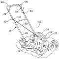
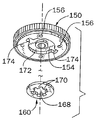
図1は、内燃エンジン12及びこのエンジン12を自動的に始動するための装置14を組み込んだ芝刈機10を示す。芝刈機10、内燃エンジン12、及びエンジン始動装置14の各々は、本発明の実施例を含む。
FIG. 1 shows a
芝刈機10は、デッキ16及びこのデッキ16から外方及び上方に延びるハンドルアッセンブリ18を有する。ハンドルアッセンブリ18は、デッキ16に取り付けられた下端20、及びデッキ16の上方にオペレータが芝刈機10を容易に取り扱うことができる位置に位置決めされた上端即ちハンドル端22を有する。オペレータは、ハンドルアッセンブリ18を操作することによって、芝刈機10の移動を制御できる。内燃エンジン12はデッキ16に取り付けられている。エンジン12は垂直シャフト型であり、従来構造の多くの構成要素を含む。しかしながら、これらのエンジン構成要素の大部分はエンジンハウジング24によって実質的に包囲されており、及びかくして図1には示してない。
The
図1の芝刈機10には、エンジン始動装置14の他に巻き込みスタータ(図示せず)が設けられている。この巻き込みスタータは、フライホイール26の上に取り付けられている(図2のフライホイール26を参照されたい)。シュラウド28が巻き込みスタータに取り付けられており、巻き込みスタータに作動的に連結された引っ張りコード30がシュラウド28を通って外方に延びている。引っ張りコード30を使用しない場合には、引っ張りコード30のハンドル端32は、ハンドルアッセンブリ18の上端22の近くに配置されたコードマウント34に取り付けてある。
In addition to the engine starter 14, the
先ず最初に、本発明を具体化するエンジン始動装置14は、芝刈機10で使用するのに特に適しており、このエンジン始動装置14は、手持ち式の園芸用機器、除雪機ブロワー、発電機を含むがこれらに限定されない様々な他の手動操作可能な屋外用動力機器及び機械に組み込むこともできるということに着目しなければならない。従って、本発明は、添付図面に示し且つ本明細書中に説明した芝刈機10又はエンジン12に限定されない。エンジン始動装置14をどのようにして様々な種類の機械及び/又は様々な種類のエンジンで使用するように適合させるのかは、添付図面及び説明から当業者に明らかになるであろう。
First of all, an engine starter 14 embodying the present invention is particularly suitable for use with a
図1を再度参照すると、細長いデッドマンハンドル又はベイルハンドル36の形態のエンジン制御装置がハンドルアッセンブリ18の上端22に相互連結されている。ベイルハンドル36は、ハンドルアッセンブリ18に配置された二つの枢動ピン38を中心として枢動自在に支持されており、上端22から遠ざかる方向に回転するように押圧されている。オペレータがハンドルアッセンブリ18の上端22及びベイルハンドル36を一緒に握ると、ベイルハンドル36が二つの枢動ピン38を中心として下方に枢動し、次いで、上端22と隣接した始動位置又は作動位置に保持できる。ベイルハンドル36を離すと、ベイルハンドル36は図1に示す停止位置に向かって自動的に回転する。当該技術分野で周知のように、ベイルハンドル36を離すと、エンジンの点火を不能にし及び/又はブレーキを作動することによってエンジン12の停止が開始される。
Referring again to FIG. 1, an engine controller in the form of an elongated deadman handle or bail handle 36 is interconnected to the
押しボタン40の形態の手動アクチュエータが、ベイルハンドル36の好ましくは一方の枢動ピン38と隣接した位置で、ハンドルアッセンブリ18に取り付けられている。押しボタン40は、ベイルハンドル36に作動的に相互連結されている。以下に説明するように、オペレータは、エンジン始動装置14を作動させてエンジン12を始動することができる。これは、押しボタン40を押し、押しボタン40を押したままベイルハンドル36を始動位置に向かって下方に枢動することによって行われる。かくして、エンジン始動装置14は、オペレータが二つの別々の動作を行わなければ、即ち押しボタン40を押し(及び保持し)且つベイルハンドル36を下方に枢動しなければ作動させることができない。別の態様では、ベイルハンドル36に代えて、一つ又はそれ以上の押しボタン装置、レバー機構、又は他の種類の手動アクチュエータを使用できる。このような変更は、詳細な説明及び本願に含まれる図面が開示された当業者に明らかになるであろう。
A manual actuator in the form of a
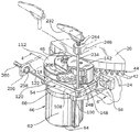
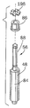
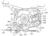
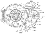
図2は、エンジン始動装置14の拡大図である。この始動装置は、エンジンハウジング24に取り付けられた、リングギヤ44の一組の外歯42と隣接して位置決めされている。リングギヤ44は、フライホイール26の部分であり、両構成要素は、エンジン12のクランクシャフト(図示せず)に回転自在に取り付けられている。フライホイール26を時計廻り方向に回転させると、フライホイール26はクランクシャフトを始動方向又は作動方向に回転し、エンジン12を初期エンジン回転に亘って駆動する。エンジン12が始動すると、エンジンはそれ自体の動力で回転を開始し、次いでクランクシャフト及びフライホイール26を駆動回転できる。
FIG. 2 is an enlarged view of the engine starting device 14. The starter is positioned adjacent to a set of
説明の目的で、クランクシャフト及びフライホイール26は、エンジンが作動している状態で一緒に回転する回転自在のエンジン部材又はアッセンブリと言うことができる。回転自在のエンジンアッセンブリは、更に、始動方向に回転してエンジンを初期始動回転に亘って駆動できる。本発明の変形例では、回転自在のエンジンアッセンブリは、更に、一つ又はそれ以上の出力装置(例えば、芝刈機の切断ブレード)を含む。
For illustrative purposes, the crankshaft and
エンジン12の停止は、ベイルハンドル36を解放した時に開始される。しかしながら、クランクシャフト、フライホイール26、及び他の出力装置(例えば、芝刈機の切断ブレード)を含むエンジンの回転部材には、エンジンを停止した後でも、クランクシャフト及びフライホイール26を追加の回転に亘って駆動回転し続けるのに十分な角運動量がある。ベイルハンドル36を離した後(即ちエンジンの点火を停止した後)のクランクシャフト及びフライホイール26のこのような追加の回転によって特徴付けられる状態は、一般に、エンジンのコーストダウン即ち惰性停止(coast down)と呼ばれる。従来技術では、エンジンのコーストダウン中にフライホイール26を直接係合し、クランクシャフト、フライホイール26、及び任意の出力装置の回転を迅速に停止させるフライホイールブレーキ装置を使用することが周知である。本発明の一つの特徴では、エンジンのコーストダウン中に、回転しているクランクシャフト及びフライホイール26のエネルギを吸収して蓄えるように機能するブレーキ機構としてエンジン始動装置14を使用する。変形例では、芝刈機10又は他の機械には、本発明のエンジン始動装置14並びに従来のフライホイールブレーキの両方が設けられている。これらの用途では、エンジン始動装置14は、フライホイールブレーキがエンジンのコーストダウンを迅速に終了させるのを補助するのに使用される。
The
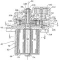
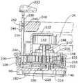
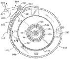
次に図2、図3、及び図4を参照すると、エンジン始動装置14には、ばねケーシング46、このばねケーシング46の中央を通って垂直に支持されたばね駆動部材即ちばねシャフト48、及びばね駆動シャフト48と係合できるコイル状金属バンドの形態の弾性部材又はぜんまいばね50(図4参照)が設けられている。垂直方向中央軸線52がばねシャフト48を通って長さ方向に延びており、クランクシャフトとほぼ平行な関係で位置決めされている(例えば、図3のBを参照されたい)。ばねシャフト48は、ばねケーシング46から、このばねケーシング46の上方に支持された枢動自在のハウジング54を通って上方に延びている。
2, 3 and 4, the engine starter 14 includes a
以下に説明するように、枢動自在のハウジング54は、中央軸線52を中心として揺動するように枢動自在に支持されている。枢動自在のハウジング54は、エンジンのコーストダウン中にフライホイール26と係合してぜんまいばね50の巻き上げを行うことができる回転自在のシャフトアッセンブリ即ち入力アッセンブリ56を保持する(図3のD参照)。枢動自在のハウジング54は、更に、入力アッセンブリ56と係合できるトランスミッション即ち駆動アッセンブリ58を保持する(図3のA参照)。このアッセンブリ58は、入力アッセンブリ56と係合でき、入力アッセンブリ56とばねシャフト48との間に作動的に位置決めされている。最後に、枢動自在のハウジング54は、リングギヤ44と選択的に係合してフライホイール26を駆動回転し、エンジン12の始動を開始できる回転自在の出力アッセンブリ60を保持する(図3のA参照)。これらのアッセンブリ56、58、60の各々及びその作動を以下に詳細に論じる。
As will be described below, the
エンジン始動装置14は、リングギヤ44を介さずにフライホイール26と直接係合するように容易に適合できるということに着目しなければならない。例えば、回転自在の出力アッセンブリ60は、フライホイール26の外面(例えば一体に鋳造された歯)と噛み合うように適合させることができる。
It should be noted that the engine starter 14 can be easily adapted to engage directly with the
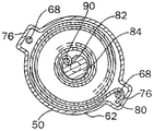
図3のBに最もよく示すように、ばねケーシング46は、円筒形部分62、全体に平らな底部64、ケーシングトップ66を含み、これらはボルト68等で互いに接合されている。平らな底部64には、直径方向反対側の二つの平らなフランジ70及びベアリング74が配置される中央孔72が形成されている。円筒形部分62には、直径方向反対側の二つの垂直な突出部76が形成されており、これらの突出部は、内方に面したチャンネル78を画成する。最終組み立てでは、円筒形部分62、平らな底部64、及びケーシングトップ66は、チャンネル78を平らなフランジ70及びケーシングトップ66に設けられたボルト穴(図示せず)と整合し、ボルト68を通すことによって互いに接合される。
As best shown in FIG. 3B, the
ぜんまいばね50は、好ましくは、ステンレス鋼又は炭素鋼構造でできた細長く比較的広幅の金属製バンドの形態である。本発明の幾つかの形態では、ぜんまいばね50の幅は、約2.54cm乃至7.62cm(約1インチ乃至3インチ)である。一つの特定の実施例では、ぜんまいばね50は、幅が7.62cm(3インチ)であり、エンジン12を7回転又は8回転に亘って回転させるのに十分な始動トルクを発生できる。しかしながら、ぜんまいばね50の幅、長さ、及び/又は厚さはこれよりも大きくても小さくてもよいということに着目されたい。更に、弾性部材は、圧縮ばね又はゴム又は合成材料製の高強度弾性バンドを含む幾つかの変形例の形態であるのがよい。
The
ぜんまいばね50の外縁部又は端部80は、図3のBに示すように一方のチャンネル78内に折り込んである(図8を更に参照されたい)。次いで、外端80をボルト68でこのボルトと垂直突出部76との間に固定する。
The outer edge or end 80 of the
図3のBを参照すると、ぜんまいばね50は、内側端部即ち縁部82を有する。この縁部は、全体として、ばねケーシング46の中央近くでばねシャフト48と隣接して(図8を更に参照されたい)位置決めされている。ばねシャフト48の太くなった心棒部分84がばねケーシング46内の中央に垂直に位置決めされており、ベアリング74及びフランジベアリング86によって回転自在に支持されている。ばねシャフト48の上部分88は、下心棒部分84よりも細く形成されており、枢動自在のハウジング54を通って上方に延びている。添付図面に示す実施例では、ばねシャフト48の上部分88の直径は、好ましくは、約0.991cm(約0.390インチ)であるのに対し、下心棒部分84の直径は、好ましくは、約1.575cm(約0.620インチ)である。図8の平面図に最もよく示してあるように、下心棒部分84の直径の一部を切り欠いて垂直方向に延びるアイレット90を形成し、ぜんまいばね50の内側端部82を完全なループに形成し、次いでこのループをアイレット90と係合させ、又はここにフック止めする。
Referring to FIG. 3B, the
本出願人は、詳細に亘る試験により、「アイレット」型のばね−ばねシャフト連結が最も好ましい結果をもたらすということを発見した。「アイレット」型連結では、ばね50に加わっていた負荷がひとたび完全に解放された後、ばね50をばねシャフト48にフック止めされた状態から外すことができ、及びぜんまいばね50を全く損傷せずにばねシャフト48を回転させ続けることができる。詳細には、ぜんまいばね50を巻き上げているとき及び巻きが解かれるときに作用する応力集中が最小になる。その結果、添付図面に示す実施例は、数千回の(エンジン始動)サイクルに亘って故障なく十分に作動するということがわかった。
Applicant has discovered through extensive testing that an “eyelet” type spring-spring shaft connection provides the most favorable results. In an “eyelet” type connection, once the load applied to the
図3のBを再度参照すると、ばねケーシング46のケーシングトップ66は、デッキ面92及びこのデッキ面92から全体に外方に延びる二つの取り付けブラケット94及び96を含む。第1取り付けブラケット94がエンジンハウジング24のスターターマウント(図示せず)と隣接して位置決めされるのに対し、第2取り付けブラケット96は全体に反対方向に延び、このブラケットもまたエンジンハウジング24に固定される。取り付けブラケット94及び96は、ばねケーシング46及び枢動自在のハウジング54の両方をエンジンハウジング24と隣接して、及びリングギヤ44の外歯42と隣接して支持する。更に、ケーシングトップ66は、小さなアイレット100が設けられた前方に延びる定置アーム98を有する。以下に説明するように、枢動自在のハウジング54は、アイレット100に取り付けられた戻しばね102を介して押圧されている。
Referring again to FIG. 3B, the
図3のBを参照すると、ケーシングトップ66のデッキ面92は、中央軸線52と同軸に整合して位置決めされた垂直ボア106を持つ円形のポスト104を含む。枢動自在のハウジング54の下枢動ブラケット108は、円形のポスト104の上方に位置決めされており、垂直ボア106と軸線方向で整合した下開口部110を有する。次いで、フランジベアリング86をばねシャフト48の周囲に同心に取り付ける。このベアリングは、垂直ボア106及び下開口部110を通って上方に延びる(図3のD及び図4参照)。ばねシャフト48は、フランジベアリング86を通って枢動自在のハウジング54内に延び、フランジベアリング86の内側面から離間される。従って、ばねシャフト48はフランジベアリング86内で自由に回転できる。
Referring to FIG. 3B, the
図3のA及びB、及び図4を参照すると、枢動自在のハウジング54は、下枢動ブラケット108と対応する上枢動ブラケット112とを隣接させることによって形成される。図3のBで最もよくわかるように、下枢動ブラケット108は、下開口部110がほぼ中央に配置された全体に平らなデッキ114及び比較的短い上方に延びる外周壁116を有する。フランジ即ちレバーアーム118が周壁116から前方に延びている。このレバーアーム118には、制御ケーブル122に連結するための孔120及び戻しばね102の一端が固定される孔124が設けられている。
With reference to FIGS. 3A and 3B and FIG. 4, the
次に図3のAを参照すると、上枢動ブラケット112は、下方に延びる外壁126、多レベル上区分128、及び外壁126の一部から延びる下フランジ区分130を含む。上枢動ブラケット112は、ボア即ち上開口部134が貫通した上方に延びる円形のハブ132を更に含む。上開口部134は、下枢動ブラケット108の下開口部110と同軸に整合して配置されており、中央軸線52を中心として位置決めされる。上シャフトベアリング136が上開口部134内に保持され、上枢動ブラケット112が上シャフトベアリング136の外面と摩擦係合する。しかしながら、上シャフトベアリング136の内側面は、ばねシャフト48の外面から離間されており、ばねシャフト48は上シャフトベアリング136内で自由に回転できる。従って、枢動自在のハウジング54は、フランジベアリング86の外面を中心とした下枢動ブラケット108の自由回転及びばねシャフト48の外面を中心とした上シャフトベアリング136の自由回転により、中央軸線52を中心として回転するように、又は揺動運動するように支持されている。更に、ばねシャフト48は上シャフトベアリング136を通って上枢動ブラケット112の上方に延びている。枢動自在のハウジング54をばねシャフト48に保持するため、リテーナクリップ138がばねシャフト48に取り付けられている。
Referring now to FIG. 3A, the
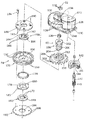
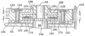
図4の断面図を参照すると、枢動自在のハウジング54の右側の区分には入力アッセンブリ56が配置されており、左側の区分には出力アッセンブリ60及びトランスミッションアッセンブリ58が配置されている。入力アッセンブリ56は、上枢動ブラケット112と下枢動ブラケット108との間に回転自在に支持されており且つばねシャフト48と全体に平行な関係で位置決めされた入力シャフト140を含む。摩擦ローラー142が入力シャフト140にこのシャフトとともに回転するように固定的に取り付けられている。図3のAを更に詳細に参照すると、摩擦ローラー142は、好ましくは、硬質の金属製コア144及び好ましくはゴム材料で形成された外面146を有する。摩擦ローラー142は、フライホイール26の外面と隣接して位置決めされており(図2参照)、以下に説明するように、枢動自在のハウジング54とともに横方向に移動でき即ち揺動してフライホイール26と回転係合できる。
Referring to the cross-sectional view of FIG. 4, an
入力アッセンブリ56は、摩擦ローラー142の下で入力シャフト140に取り付けられた入力ギヤ148を含む。この入力ギヤ148は、トランスミッションアッセンブリ58のスパーギヤ即ちクラッチギヤ150と全体に整合しており且つこれと係合する。フライホイール26が摩擦ローラー142との摩擦係合により入力シャフト140を回転すると、入力ギヤ148がクラッチギヤ150を回転駆動する。
The
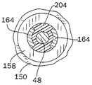
クラッチギヤ150は、フランジベアリング86の上方の軸線方向位置でばねシャフト48を中心として取り付けられている(例えば、図4及び図5を参照されたい)。図3のA及びCで最もよくわかるように、クラッチギヤ150には、円形の上凹所152、円形の下凹所154、及びこれらの円形凹所152、154から半径方向外方に配置された等間隔に間隔が隔てられた4つのリベット穴156が形成されている。円形の上クラッチプレート158が上凹所152内に位置決めされ、下クラッチプレート160が下凹所154内に位置決めされる。上クラッチプレート158は、上方に延びる二つの湾曲壁即ちカム164が設けられた(図6を更に参照されたい)円形の輪郭(即ち「蝶ネクタイ」)を持つことを特徴とする中央開口部162を有する。二つの湾曲カム164は、中央開口部162の内側で互いに間隔が隔てられており、これらのカムの側壁面166は、上クラッチプレート158のカム面即ち係合面を形成する。同様に、下クラッチプレート160は中央開口部168を有するが、この中央開口部168は、複数の内係合歯170を形成する平らな星型の輪郭を有する。
The
変形例では、中央開口部162、168は、輪郭が異なり、異なる係合面又は歯形体を画成することを特徴とする。これらの形体の設計は、部分的には、クラッチプレート158及び160に伝達される単位荷重及び材料強度で決まる。図3のA及びCに示す実施例では、中央開口部168は、荷重を更に分配し、下クラッチプレート160に作用する応力を小さくするため、更に大きな係合面(及び更に多くの係合歯170)を提供するように設計されている。
In a variant, the
特に図3のCを参照すると、下凹所154には、中央ハブ172及び直径方向反対側の位置から半径方向外方に延びる凹所をなした一対のキー溝174が形成されている。下クラッチプレート160は、下凹所154内に位置決めされ、中央ハブ172を中心として同心をなして配置される。下クラッチプレート160とクラッチギヤ150との間には、ベルビルワッシャ176及び摩耗プレート178が下凹所154内に配置されている(図3のA参照)。摩耗プレート178に設けられた外方に延びる二つのフランジ即ちキー180は、凹所をなしたキー溝174によって受け入れられており摩耗プレート178が回転しないようにする。摩耗プレート178は、更に、ベルビルワッシャ176から下クラッチプレート160へ荷重を分配する。変形例では、波形ワッシャ又は他の種類のばねワッシャをベルビルワッシャ176の代わりに使用できる。
Referring particularly to FIG. 3C, the
次に図3のA及び図5を参照すると、トランスミッションアッセンブリ58は、クラッチギヤ150の下に配置されたラチェットホイール182を更に含む。ラチェットホイール182は、中央開口部184及び外ラチェット歯186を有する。図5に示すように、ラチェットホイール182はフランジベアリング86を中心として同心をなして配置されており、他のラチェット歯186がクラッチギヤ150の外周の直ぐ下で外方に延びる。更に、一組のリベット穴190及び中央開口部192を持つ全体に平らなディスク188が、上クラッチプレート158の上方で円形の上凹所152内に位置決めされている。ショルダーリベット194は、穴190、クラッチギヤ150、及びラチェットホイール182を通って延び、係止されてトランスミッションアッセンブリ58の構成要素に固定される。従って、トランスミッションアッセンブリ58は、以下の構成要素を含む。即ち、ディスク188、クラッチギヤ150、摩耗プレート178、ベルビルワッシャ176、ラチェットホイール182、及び上下のクラッチプレート158、160を含む。トランスミッションアッセンブリのこれらの構成要素は、通常は、クラッチギヤ150と入力ギヤ148との間の回転係合時にユニットをなして一緒に回転する。変形例では、トランスミッションアッセンブリ58は、ボルト、ねじ、又は同様の従来の固定手段を使用して固定できる。
With reference now to FIGS. 3A and 5, the
次に図3のD、図7、並びに図5を参照すると、フランジベアリング86の真上の位置で駆動クラッチエレメント196がばねシャフト48に固定的に取り付けられている。図7の平面図に示すように、クラッチエレメント196は、下クラッチプレート160の中央開口部168の星型の輪郭と一致する星型形態を有し、下クラッチプレート160の係合歯170と回転係合する。クラッチギヤ150を入力ギヤ148によって時計廻り方向に回転させると、下クラッチプレート160がクラッチエレメント196を駆動し、ばねシャフト48を時計廻り方向に回転駆動し、これによってぜんまいばね50を巻き上げる。ぜんまいばね50を所定回転数に亘って巻き上げると、ぜんまいばね50によって及ぼされる抵抗が大きくなり、下クラッチプレート160とクラッチギヤ150との間の係合をスリップさせ、トランスミッションアッセンブリ58をばねシャフト48と係合した状態から解除する。その結果、ばねシャフト48の回転が停止し、ぜんまいばね50を巻き過ぎないようにする。
Referring now to FIG. 3D, FIG. 7, and FIG. 5, the drive
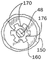
次に、図3のA及び図4を参照すると、出力アッセンブリ60は、クラッチギヤ150の上凹所152と上枢動ブラケット112との間でばねシャフト48に取り付けられた螺旋状シャフト198を含む。この螺旋状シャフト198には、時計廻り方向で軸線方向上方に延びる螺旋状の溝又は軌道200が形成されている。この溝又は軌道は、上枢動ブラケット112の下面と隣接して位置決めされたシャフトヘッド202で終端する。上クラッチプレート158のカム164は上方に延びており、螺旋状シャフト198の下部分204と係合する(図5参照)。図6に最もよく示すように、下部分204は、上クラッチプレート158の中央開口部162の輪郭と一致する形態又は形体を有し、従って、上クラッチプレート158のカム面166と積極的に係合できる。
3A and 4, the
出力アッセンブリ60は、ディスク188の上方に位置決めされたピニオンギヤ206を更に含む。このピニオンギヤは、螺旋状シャフト198の周囲に軸線方向移動及び回転移動するように取り付けられている。ピニオンギヤ206は、一組の外歯208及び盛り上がった中央ハブ210を有する。このハブには、中央開口部が設けられている(図3のA参照)。中央開口部の内側面には、螺旋状シャフト198の軌道200と一致し且つこれと係合できる螺旋状の溝又は軌道212が形成されている。従って、螺旋状シャフト198がばねシャフト48とともに反時計廻り方向に回転すると、ピニオンギヤ206が螺旋状シャフト198を中心として回転し、軸線方向上方に移動する。
The
ピニオンギヤ206がシャフトヘッド202に至ると、ピニオンギヤ206の軸線方向移動が停止し、螺旋状シャフト198が、好ましくは、ピニオンギヤ206をリングギヤ44と同じ回転平面内で駆動する。次いで、ピニオンギヤ206がリングギヤ44の外歯42と噛み合い、リングギヤ44及びフライホイール26を時計廻り方向即ち始動方向に回転駆動する。作動のこの段階で、ピニオンギヤ206は、上位置即ち係合位置(図4に破線で示す)にあると言う。しかしながら、エンジン12が始動速度を得ると、リングギヤ44の外歯42がオーバーランし、次いでピニオンギヤ206の外歯208を駆動し、これによってピニオンギヤ206を螺旋状シャフト198を中心として回転し、軸線方向下方に移動する。ピニオンギヤ206は、その後、トランスミッションアッセンブリ58の上方の下位置即ち係合解除位置(図4に実線で示す)に戻る。
When the
螺旋状シャフト198はばねシャフト48とともに回転するように取り付けられているが、螺旋状シャフト198がピニオンギヤ206を回転駆動し、リングギヤ44と初期係合状態にしたとき、上クラッチプレート158と螺旋状シャフト198の下部分204との間の摩擦係合により、螺旋状シャフト198をばねシャフト48に対してスリップさせることができる。しかしながら、エンジンが回転し始めると(大きな荷重が出力アッセンブリ60によって加えられる)、上クラッチプレート158と螺旋状シャフト198との間の摩擦係合により、螺旋状シャフト198がスリップしないようにする。かくして、エンジン12は回転し続け、ピニオンギヤ206がリングギヤ44を始動時に亘って駆動する。
The
螺旋状シャフト198の螺旋状軌道200は、ばねシャフト48が時計廻り方向に回転する場合(即ちぜんまいばね50が巻き上げられ、即ち荷重が加えられた場合)には、ピニオンギヤ206が螺旋状シャフト198を中心として軸線方向上方に移動することを阻止するということにも着目しなければならない。かくして、出力アッセンブリ60は、ばねシャフト48が反時計廻り方向に回転している場合にだけ、リングギヤ44を回転駆動するように作動できる。
The
図1乃至図19は、本出願人によるばね係止機構の第1実施例を例示する。ばね係止機構は、ぜんまいばね50が巻き解かれてばねシャフト48を回転することを阻止するように作動する。更に、手動作動可能なキー装置を作動してばね係止機構を係合位置に係止し、ぜんまいばね50が不時に解放されたり巻き解かれたりしないようにする。これらは、以下に説明するキー装置の二つの態様である。
1 to 19 illustrate a first embodiment of the spring locking mechanism by the applicant. The spring locking mechanism operates to prevent the mainspring 50 from being unwound and rotating the
先ず最初に図3のBを参照すると、第1実施例のばね係止機構は爪214を含み、この爪は、定置ねじ216を中心として所定限度内で回転するように取り付けられており、ねじ216とトーションばね218との間に固定されている。トーションばね218もまた、ねじ216を中心として同心に取り付けられており、ねじ216は、トーションばね218及び爪214の両方をケーシングトップ66の定置のデッキ面92に固定する。下枢動ブラケット108に設けられた細長いスロット220は、ねじ216がデッキ面92まで下方に延びることができるが、爪214を下枢動ブラケット108の上方に配置できるように形成されている。以下に説明するように、スロット220は、更に、枢動自在のハウジング54が、ねじ216が邪魔にならずに枢動でき又は揺動できるような形状になっている。
Referring first to FIG. 3B, the spring locking mechanism of the first embodiment includes a
爪214は、円形の枢着端即ち第1端222を有し、これを通ってねじ216が延びる。爪214は、カム面226を画成する湾曲した第2端224を更に有する。更に、トーションばね218は、デッキ面92に固定された第1端228及び爪214と係合する第2端230を有する。トーションばね218は、爪214を時計廻り方向に押圧してラチェットホイール182と係合させるように機能する。爪214の係合位置では、爪214のカム面226がラチェットホイール182の外ラチェット歯186と係合し且つこれに係止する。図11の平面図は、係合位置に配置された爪214を示す。
The
爪214は、係合位置に配置されると、ラチェットホイール182が反時計廻り方向に回転しないようにする。ばねシャフト48はもまた反時計廻り方向に回転しないようにされ、このようにして、ぜんまいばね50が巻き解かれてばねシャフト48を回転駆動することがないようにする。しかしながら、爪214が外ラチェット歯186の一方の側部としか係合できないように、爪214及び外ラチェット歯186が形成されているため、ラチェットホイール182が時計廻り方向に回転することは妨げられない。従って、爪214が係合位置にあるとき、クラッチギヤ150の時計廻り方向に回転時にぜんまいばね50を巻き上げることができる。
When the
上述のように、キー装置には二つの態様がある。キー装置の第1態様を図1乃至図12に示し、キー装置の第2態様を図13乃至図19に示す。キー装置の第1態様を以下に説明し、その後、第2態様を以下に説明する。 As described above, the key device has two modes. A first mode of the key device is shown in FIGS. 1 to 12, and a second mode of the key device is shown in FIGS. The first aspect of the key device will be described below, and then the second aspect will be described below.
キー装置の第1態様は、取り外し自在のキーハンドル232、キーロッド234、及び回転自在のカム236を含む。キーハンドル232は、垂直ボア即ちキー溝240が下面に設けられた下方に延びるポスト238(図10参照)を更に含む。キー溝240及びかくしてキーハンドル232は、キーロッド234から上方に延びるキーポスト242と係合できる。キー溝240とキーポスト242との係合により、キーハンドル232を回転させることによってキーロッド234を回転できる。更に、キーハンドル232を回転させることによって回転自在のカム236を回転できる。
The first aspect of the key device includes a removable
図10に示すように、キーロッド234は、エンジンハウジング24から延びる支持ブラケット246に配置されたキー支持孔244で支持されている。キーハンドル232のキーハンドルポスト238をキー支持孔244に挿入してキーポスト242と係合し、回転自在のカム236を手動で作動できる。しかしながら、キーハンドル232をキー支持孔244から取り外すことができる。取り外すと、キーロッド234及び回転自在のカム236は手動で作動できなくなる。
As shown in FIG. 10, the
図9及び図10を参照すると、細長いキーロッドスロット248が枢動自在の上ブラケット112の下フランジ区分130に形成されており、その結果、キーロッド234は下枢動ブラケット108内に及びこれを通って延びることができる。キーロッドスロット248は、更に、枢動自在のハウジング54を以下に説明するように制御ケーブル122で移動したとき、枢動自在のハウジング54がキーロッド234を通って摺動できるように形成されている。
9 and 10, an elongated
図9に示すように、回転自在のカム236は、延長カム部分250及びこの延長カム部分250からずれた背部252を有する。回転自在のカム236は、延長カム部分250が爪214の第2端224と係合し且つ背部252が枢動自在の下ブラケット108の外壁116と摩擦係合するように反時計廻り方向に回転させることができる。この位置では、回転自在のカム236は、爪214がラチェットホイール182から外れないようにし、ぜんまいばね50が不時に巻き解かれないようにする。図9は、係合位置に配置された爪214及び係止位置に配置されたキー装置の回転自在のカム236を示す。
As shown in FIG. 9, the
図11は、係止位置から係合解除位置即ち係止解除位置まで時計廻り方向に回転させた回転自在のカム236を示す。回転自在のカム236が係合解除位置にあるとき、カムはもはや爪214と係合しない。従って、爪214は、ラチェットホイール182から係合解除するように解放でき、ぜんまいばね50を巻き解くことができる。更に、図11及び図12に示すように、枢動自在のハウジング54は、制御ケーブル122を引っ張ることによって時計廻り方向に移動できる。図11では、回転自在のカム236は、キーロッドスロット248の下部分と隣接して位置決めされる(図11の平面図に示すように)が、枢動自在のハウジング54を時計廻り方向に揺動すると、キーロッドスロット248の上部分が移動し、回転自在のカム236に近付く。枢動自在のハウジング54は、定置ねじ216及びキーロッド234を越えて摺動する(図12参照)。入力シャフト140用の下ベアリングとして役立つ上方に延びるボス254(図3のB及び図4参照)が下枢動ブラケット108に設けられている。ボス254は、枢動自在のハウジング54が時計廻り方向に揺動するとき、爪214をラチェットホイール182から外す。
FIG. 11 shows the
図2を参照すると、第3取り付けブラケット256がエンジンハウジング24から延びており、このブラケットには、ケーブルマウント258を支持する孔(図示せず)が設けられている。ケーブルマウント258は、軸線方向に移動自在の制御ケーブル122(平らなボーデンケーブル)を収容したケーブルケーシング260の一端を支持する。制御ケーブル122は、押しボタン装置40及び/又はベイルハンドル36に相互連結されており、これにより移動できる。制御ケーブル122はケーブルマウント258から延びており、レバーアーム118の孔120と係合する。次に、図9及び図12を参照すると、制御ケーブル122を内方又は外方に移動してレバーアーム118を移動し(押しボタン装置及び/又はベイルハンドル36を作動することによって)、枢動自在のハウジング54を揺動運動で移動できるのがよい。
Referring to FIG. 2, a
図11及び図12の平面図を参照すると、戻しばね102がレバーアーム118を定置アーム98に相互連結し、枢動自在のハウジング54を反時計廻り方向に押圧する。ベイルハンドル36を解放し、エンジン12の停止を開始するとき、戻しばね102が枢動自在のハウジング54を巻き上げ位置と呼ばれる位置まで反時計廻り方向に揺動する。
11 and 12, the
図9及び図11に示す巻き上げ位置では、摩擦ローラー142がフライホイール26と回転係合し、これによって反時計廻り方向に回転する。その結果、入力ギヤ148及び入力シャフト140もまた反時計廻り方向に回転し、入力ギヤ148がクラッチギヤ150及びトランスミッションアッセンブリ58の残りを時計廻り方向に回転する。次いで、トランスミッションアッセンブリ58がばねシャフト48を時計廻り方向に回転することによりぜんまいばね50を巻き上げる。エンジンのコーストダウンが終了するとき、爪214がラチェットホイール182と係合してこれと相互係止し、これによりばねシャフト48の反時計廻り方向回転を阻止し、ぜんまいばね50が巻き解かれないようにする。
9 and 11, the
押しボタン40を押し、ベイルハンドル36を下方に枢動させると、制御ケーブル122が枢動自在のハウジング54を時計廻り方向に、図12に示す巻き解き位置即ち始動位置と呼ばれる位置まで揺動する。枢動自在のハウジング54の巻き解き位置では、摩擦ローラー142がフライホイール26から遠ざかる方向に移動され、回転係合した状態から解放される。枢動自在のハウジング54を時計廻り方向に移動し続けると、ボス254が爪214と接触し、爪214をラチェットホイール182と係合した状態から解放する。次いで、ぜんまいばね50を巻き解いてばねシャフト48及び螺旋状シャフト198を反時計廻り方向に回転できる。これに応じて、ピニオンギヤ206が螺旋状シャフト198を中心として軸線方向上方に移動し、リングギヤ44と回転係合し、リングギヤ44及びフライホイール26を時計廻り方向即ち始動方向に回転させる。次いで、エンジン12の始動に十分な初期始動回転によりエンジン12を駆動する。最後に、エンジン12が始動し、所定速度に達したとき、リングギヤ44がピニオンギヤ206を螺旋状シャフト198を中心として回転し、係合解除位置まで下方に移動する。
When the
図13乃至図19に示すキー装置の第2態様では、キー装置の第1態様と同様の方法で(即ち、爪214をラチェットホイール182と係合した状態に係止する)作動する。この態様は、キーロッド234を爪214に近付けて配置できない、エンジンの用途に特に適している。
The second mode of the key device shown in FIGS. 13 to 19 operates in a manner similar to that of the first mode of the key device (that is, the
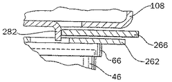
キー装置の第2態様は、キー装置の第1態様にはない幾つかの特徴を含む。図13に示すように、これらの追加の特徴には、定置支持プレート262、枢動リンク264、摺動部材266、及びカムポスト268が含まれる。定置支持プレート262は、ケーシングトップ66上に下枢動ブラケット108の下に取り付けられており、キー装置のこの態様では、枢動リンク164用の枢着点を提供する。この態様では、定置支持プレート262には、更に戻しばね102を取り付けるための定置アーム98が設けられている。
The second aspect of the key device includes several features that are not present in the first aspect of the key device. As shown in FIG. 13, these additional features include a
枢動リンク264は定置支持プレート262に枢着されており、キーロッド234によって直接的に作動できる。枢動リンク264は、摺動部材266の一端にピン止めされている。この摺動部材は、定置支持プレート262と下枢動ブラケット108との間を延びる。カムポスト268が摺動部材266の反対端に固定されており、このポストは、定置支持プレート262のガイドスロット270を通って下方に延び、下枢動ブラケット108のウィンドウを通って上方に延びる。枢動リンク264をキーロッド234によって回転させることによって、摺動部材266及びカムポスト268を図15に示す位置と図17に示す位置との間で移動する。
The
図17は、キー装置の第2態様を係止位置で示す。この位置では、枢動リンク264が反時計廻り方向に回転させてあり、そのためカムポスト268が爪214と係合する。この位置では、カムポスト268は、爪214がラチェットホイール182から外れないようにし、且つぜんまいばね50が巻き解かれないようにする。
FIG. 17 shows the second mode of the key device in the locked position. In this position, the
図15及び図16は、キー装置の第2態様を係止解除位置で示す。この位置では、キーハンドル232及び枢動リンク264が時計廻り方向に回転させてあり、そのため、カムポスト268がガイドスロット270に沿って摺動し、爪214から遠ざかるように移動する。図16では、爪は、係止解除されているけれども、ラチェットホイール182と未だに係合している。図15では、枢動自在のハウジング54を移動することにより、爪214がラチェットホイール182から係合解除されている。
15 and 16 show the second mode of the key device in the unlocked position. In this position, the
図13乃至図19には、特定の場合が生じたときにエンジン12の点火システム回路を接地することによってエンジン12を停止するための装置及びシステムが例示されている。他の図面には示してないが、本発明の全ての実施例は、エンジン停止システムを含むということは理解されよう。更に、エンジン始動装置14の上下の枢動ブラケット108、112及び他の構造的構成要素は、好ましくは、金属製の導電性材料から形成されるということに着目されるべきである。
FIGS. 13-19 illustrate an apparatus and system for stopping the
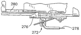
例示のエンジン停止システムは、米国特許第4,971,001号、米国特許第5,040,644号、及び米国特許第5,086,890号(これらの特許は全て、ブリッグス・アンド.ストラットン社に譲渡されており、これらの特許に触れたことにより、これらの特許に開示されている内容は本明細書中に組入れたものとする)に記載の方法で機能する。更に詳細には、図14及び図19に示すように、安全停止スイッチ272が定置支持プレート262の下面に固定的に取り付けられている。安全停止スイッチ272は、可撓性端子274及び接地接触子276を含む。
Exemplary engine stop systems include US Pat. No. 4,971,001, US Pat. No. 5,040,644, and US Pat. No. 5,086,890 (all of which are Briggs and Stratton). By touching these patents, the contents disclosed in these patents function in the manner described in this specification. More specifically, as shown in FIGS. 14 and 19, a
可撓性端子274は、点火システム(図示せず)の一次捲線に続く導体ワイヤ278に電気的に接続されている。接地接触子276は、支持プレート262の外周と隣接して配置されており、支持プレート262の上面の上に延びている。水平方向に延びる接触タブ280が、下枢動ブラケット108から支持プレート262を越えて外方に延びており、下枢動ブラケット108とともに移動できる。
The
図15に示すように、下枢動ブラケット108を回転させて爪214を係止解除したとき、接地接触子276が接触タブ280から離れ、点火システムを作動可能できる。図16に示すように、ベイルハンドル36を離すと、下枢動ブラケット108が回転して爪214を係止し、これにより接触タブ280を接地接触子276と係合させ、停止スイッチ272を接地する。この状態では、点火システムが接地され、エンジン12は作動できない。
As shown in FIG. 15, when the
図14、図16、及び図17を参照すると、タブストップ282が下枢動ブラケット108に設けられており、ここから下方に延びている。キー装置の第2態様を使用して摺動部材266を図15及び図16に示す係止解除位置から図17に示す係止位置まで移動すると、摺動部材266がタブストップ282と係合する(図18も参照されたい)。この作用により下枢動ブラケット108を時計廻り方向に回転し、摩擦ローラー142をフライホイール26を回転係合した状態から回転する。接触タブ280は、摩擦ローラー142をフライホイール26から離すと同時に接地接触子と接触して点火システムを接地させたままにするのに十分なだけ下枢動ブラケット108を回転できるのに十分広幅である。
Referring to FIGS. 14, 16, and 17, a
例示の態様以外の幾つかの態様のエンジン停止システムを使用できる。例えば、他の態様は、ベイルハンドル36等のアクチュエータの解放時にエンジンの点火システムを接地できる。別の態様では、米国特許第4,971,001号、米国特許第5,040,644号、及び米国特許第5,086,890号に記載され且つ例示された点火システム及びエンジン停止システムを本発明に直接組み込むことができる。
Several aspects of the engine shutdown system other than the illustrated aspects can be used. For example, other aspects may ground the engine ignition system upon release of an actuator such as the
図1乃至図19に示し且つ上文中に説明した実施例に対する変形例では、エンジン始動装置には、ぜんまいばねを各々収容した二つ又はそれ以上のばねケーシングが設けられているのがよい。これらのぜんまいばねは、直列で作動し、ばねシャフトを回転する。更に、複数のぜんまいばねをばねケーシング内に収容できる。更に詳細には、2.54cm(1インチ)幅の三つのぜんまいばねを互いに重ね、内側端を同じばねシャフトに相互連結し、又は同じばねシャフトによって固定するのがよい。これらの三つのばねは、この場合、並列に作動し、7.62cm(3インチ)幅の一つのぜんまいばねに匹敵する始動トルクを発生する。 In a variant on the embodiment shown in FIGS. 1 to 19 and described above, the engine starting device may be provided with two or more spring casings each containing a mainspring spring. These mainsprings operate in series and rotate the spring shaft. Furthermore, a plurality of mainsprings can be accommodated in the spring casing. More specifically, three 1 inch wide springs may be stacked on top of each other and the inner ends interconnected to the same spring shaft or secured by the same spring shaft. These three springs, in this case, operate in parallel and generate a starting torque comparable to a single spring of 7.62 cm (3 inches) width.
本発明の一つの特徴では、エンジン始動装置14は、現存の内燃エンジン12に容易に適合できる。例えば、図1乃至図19に示すエンジン12には、エンジンハウジング24と隣接して取り付けられた電気式スターターが予め設けられていた。バッテリー、オルタネータ、フライホイールブレーキ、配線、及び電気式スターターを取り外し、電気式スターターが以前に取り付けられていたのと同じ位置にエンジン始動装置14を挿入し且つ取り付ける。更に、エンジン始動装置14の図面に描いてあるピニオンギヤ206及び螺旋状シャフト198は、電気式スターターで使用されていたのと同じである。
In one aspect of the invention, the engine starter 14 can be easily adapted to an existing
図1乃至図19に示すエンジン始動装置14の入力アッセンブリ56は、変形例の形体の入力アッセンブリに容易に代えることができるということに着目しなければならない。例えば、バッテリー及び回転自在の駆動装置を持つ電気モータは、クラッチギヤ150と係合するように選択的に作動できる。変形例では、このようなバッテリー及び回転自在の駆動装置を持つ電気モータを、入力アッセンブリ56に対するバックアップ入力装置として設けることができる。
It should be noted that the
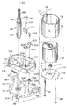
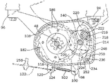
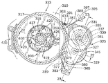
図20乃至図23は、本発明を具体化した第2エンジン始動装置を示す。この装置は、垂直クランクシャフト315を持つ第2内燃エンジン313に適用される。エンジン始動装置の特定の構成要素がフライホイール317とエンジンハウジング319との間に取り付けられている。詳細には、ぜんまいばね321がフライホイール317の下部に相互連結されており、このぜんまいばねを使用してエンジン313を初期始動回転に亘って駆動する。従って、図20乃至図23のエンジン始動装置を、本発明によるエンジン始動装置のアンダーザフライホイール態様と呼ぶ。
20 to 23 show a second engine starter embodying the present invention. This device is applied to a second
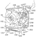
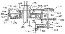
次に図22及び図23を参照すると、エンジン始動装置は、枢動自在のハウジング329内に取り付けられたピニオンシャフト325及びアイドラーシャフト327を含む、入力手段即ち入力アッセンブリ323を有する。これらの二つのシャフト325、327は、全体にフライホイール317の側方に位置決めされており、クランクシャフト315に関して全体に平行な関係にある。摩擦ローラー331がピニオンシャフト325に、摩擦ローラーを横方向に移動してフライホイール317と回転係合できる位置(図20参照)で固定的に取り付けられている。
Referring now to FIGS. 22 and 23, the engine starter has an input means or
更に、トルク制限クラッチアッセンブリ333が摩擦ローラー331の下に取り付けられており、ピニオンシャフト325と摩擦ローラー331との間に作動的に位置決めされている。クラッチアッセンブリ333は、クラッチプレート335、クラッチハウジング341、プレート337、駆動エレメント339、及び圧縮ばね(図示せず)を含む。クラッチアッセンブリ333は、エンジン始動装置14の第1実施例のトランスミッションアッセンブリ58に関して上文中に説明したのと同様の方法で機能する。ばね抵抗の所定の上昇時に、クラッチアッセンブリ333は、ぜんまいばね321を巻き過ぎないように機能する。本発明の一つの特定の実施例では、クラッチアッセンブリ333の定格は、最大約0.173m−kg(約15in−lb)である。
In addition, a torque limiting
下ピニオンギヤ343は、摩擦ローラー331の下で、ピニオンシャフト325のほぼ中間位置でピニオンシャフト325に固定的に取り付けられている。アイドラーシャフト327は、ピニオンシャフト325に対してほぼ平行な関係で取り付けられており、アイドラーギヤ345及び一組の外歯349を持つラチェットホイール347を支持する。このラチェットホイールは、アイドラーギヤ345の下でアイドラーシャフト327に固定的に取り付けられている。下ピニオンギヤ343は、アイドラーギヤ345と回転平面を共有し、アイドラーギヤ345と回転係合し、摩擦ローラー331がフライホイール317と回転係合したとき、アイドラーギヤ345及びアイドラーシャフト327を回転する。
The
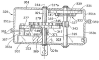
次に、図20及び図23を参照すると、枢動自在のハウジング329がエンジンハウジング319と隣接して取り付けられる。このハウジング329は、上枢動ブラケット351及び下枢動ブラケット353によって形成される。上下の枢動ブラケット351、353は、左端壁351a、353aを夫々有し、右端壁351b、353bを夫々有する。右端壁351b、353bは、一対の右フランジ359によって互いに固定されており、左端壁351a、353aは、一対の左フランジ361によって互いに固定されている。図20に最もよく示すように、枢動自在のハウジング329は、エンジンハウジング319に取り付けられており且つこのハウジングから延びる取り付けプレート363に支持されている。取り付けプレート363は全体に平らなプレートであり、上枢動ブラケット351と下枢動ブラケット353との間を延びる外部分365を含む。特に図23を参照すると、外部分365には、第1取り付けポスト367、及びベアリング371が形成されたボス即ち第2取り付けポスト369が設けられている。アイドラーシャフト327は、上枢動ブラケット351で支持された上端327a及び下枢動ブラケット353で支持された下端327bを有する。アイドラーシャフト327は、これらの間でベアリング371で回転自在に支持されている。従って、アイドラーシャフト327はベアリング371内で回転自在であるが、枢動自在のハウジング329全体は、アイドラーシャフト327とベアリング371との間の回転係合により、アイドラーシャフト327の長さ方向軸線方向373を中心として枢動自在である。
20 and 23, a
特に図20及び図23を参照すると、エンジン始動装置には、カム面379を持つ爪377、及び第1取り付けポスト367に取り付けられており且つ爪377と係合するトーションばね(図示せず)が更に設けられている。爪377は、カム面379がラチェットホイール347の外歯349と係合し、アイドラーシャフト327が反時計廻り方向に回転しないように押圧されている。更に、半島状突出プレート383が左フランジ361間に取り付けられており、これらのフランジから外方に爪377の下に延びている。バンプピン385が半島状突出プレート383から上方に延びている。このピンは、爪377と係合してこの爪377をラチェットホイール347と係合した状態から外すことができる。
20 and 23, the engine starter includes a
次に図20及び図21を参照すると、制御ケーブル389のベント端391が、右フランジ359に形成されたアイレット387と係合している。制御ケーブル389は、ケーブルマウント397に取り付けられてこのマウントによって支持された制御ケーブルケーシング395内で軸線方向に移動自在である。制御ケーブル389は、エンジンハウジング319から遠方に配置された、枢動自在のハウジング329を移動するための手動制御システム(図示せず)に相互連結できる。幾つかの実施例では、制御ケーブル389は、エンジン313から遠くに配置されたベイルハンドル、レバー、又は押しボタン等の手動アクチュエータに相互連結されている。
20 and 21, the
制御ケーブル389を操作して枢動自在のハウジング329をアイドラーシャフト327を中心として揺動し、摩擦ローラー331をフライホイール317と回転的に係合し又は係合解除することができる。図20は、枢動自在のハウジング329を係合状態即ち巻き上げ状態で、即ちエンジンのコーストダウン中の状態で示す。摩擦ローラー331はフライホイール317と噛み合い、フライホイール317の時計廻り方向回転により、摩擦ローラー331及びピニオンシャフト325を反時計廻り方向に回転する。その結果、下ピニオンギヤ343はアイドラーギヤ345を時計廻り方向に回転する。
By operating the
図21は、枢動自在のハウジング329を係合解除位置で示す。この位置では、摩擦ローラー331がもはやフライホイール317と噛み合わないように枢動自在のハウジング329を外方に移動するため、制御ケーブル389が使用されている。枢動自在のハウジング329が揺動によりフライホイール317から離れると、バンプピン385が爪377と係合し、爪377をラチェットホイール347と係合した状態から強制的に外し、アイドラーシャフト327は、次いで、反時計廻り方向に回転できる。
FIG. 21 shows the
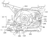
次に図22及び図23を参照すると、入力アッセンブリ323は、主ギヤ399がクランクシャフト315を中心として取り付けられたトランスミッション又は駆動手段と回転係合できる。アイドラーギヤ345は、爪377がラチェットホイール347と係合し且つこれと相互係止したときに主ギヤ399もまた相互係止されるように、主ギヤ399と噛み合う。図22を参照すると、主ギヤ399は、駆動継手401を中心として取り付けられ、ばねアーバー405が継手401の一部を中心として同心に取り付けられている。ばねアーバー405は、ぜんまいばね321の内側端415が係合できる突出部(図示せず)を含む。
Referring now to FIGS. 22 and 23, the
ぜんまいばね321は、水平上カバー409及び開放した下部を持つ駆動ハウジング即ちばねハウジング407内に取り付けられている。このばねハウジング407は、ぜんまいばね321を取り囲んでこれを包囲する外周壁411を更に有する。ぜんまいばね321の外端413は、ばねハウジング407に固定的に連結されている。
The
主ギヤ399をアイドラーギヤ345によって反時計廻り方向に回転すると、ばねアーバー405が回転し、ぜんまいばね321が巻き上げられる。爪377がラチェットホイール347と係合し且つ相互係止したとき、巻き上げられたぜんまいばね321が巻き解かれないようにする。
When the
図20及び図22の両方を参照すると、ばね出力手段即ち出力エレメントは、クランクシャフト315を中心として取り付けられており且つばねアーバー405及び主ギヤ399の上方に取り付けられた一方向クラッチアッセンブリ403を含む。クラッチアッセンブリ403は、ラチェット417、クラッチハウジング419、クラッチカバー421、及びクラッチボール423を含む。ラチェット417はばねアーバー405に固定的に取り付けられており、及び従って、アーバー405及び継手401とともに回転できる。かくして、ラチェット417は、好ましくは、入力アッセンブリ323によって主ギヤ399を回転したとき、主ギヤ399によって反時計廻り方向に回転駆動できる。逆に、ぜんまいばね321が巻き解かれるとき、ラチェット417はアーバー405とともに時計廻り方向に回転する。
Referring to both FIGS. 20 and 22, the spring output means or output element includes a one-way
ラチェット417は、等間隔に間隔が隔てられた複数の突出部即ちカム425を含む。これらのカムは、一方の側が傾斜しており、他方の側に凹所が設けられている。クラッチハウジング419は、ラチェット417を中心として同心に取り付けられており、フライホイール317を介してクランクシャフト315に固定的に相互連結されている。クラッチハウジング419は、全体にカップ状の凹所427を画成し、ここにクラッチボール423が維持され、凹所427のポケット429がラチェット417から半径方向外方に配置されている。最後に、クラッチカバー421がクラッチハウジング419の周囲からラチェット417まで延び、凹所427を包囲する。以下に説明するように、ラチェット417は、クラッチハウジング419を回転駆動するため、所定の速度範囲で時計廻り方向に即ち始動方向に回転できるが、逆方向即ち反時計廻り方向では、クラッチハウジング419を回転駆動するように作動しない。
The
クラッチハウジング419は、半径方向内方に面した複数のカム面431を更に含み、これらのカム面に対し、クラッチボール423がラチェット417のカム425によって楔係合できる。ラチェット417のカム425がクラッチボール423をカム面431に対して楔保持するとき、クラッチアッセンブリ403が係合する。ぜんまいばね321が巻き解くことができるようにし且つばねアーバー405及びラチェット417を時計廻り方向に回転駆動できるようにしたとき、このような係合が生じる。クラッチアッセンブリ403は、次いで、フライホイール317及びクランクシャフト315を時計廻り方向即ち始動方向に回転駆動し、エンジン313を初期始動回転に亘って駆動する。
The
エンジン313がそれ自体の動力によって回転を開始し、作動速度に達すると、クラッチボール423をカム425から遠ざかる方向に外方にポケット429に投げ込むのに十分な遠心力がクラッチボール423に作用する。その結果、ラチェット417がクラッチハウジングをオーバーランし、これによってクラッチアッセンブリ403がフライホイール317と回転係合した状態から解放される。
When the
図20は、巻き上げ状態のエンジン始動装置を示す。上文中に説明したように、制御ケーブル389に相互連結されたベイルハンドルや押しボタン等の手動アクチュエータの作動(例えばベイルハンドルの解放)時に巻き上げ状態にできる。戻しばね433が、右フランジ359とエンジンハウジング319との間に取り付けられており、枢動自在のハウジング329をフライホイール317に向かって押圧する。フライホイール317が時計廻り方向即ち始動方向に回転している場合(即ちエンジンのコーストダウン中)、制御ケーブル389を解放すると、戻しばね433の力により枢動自在のハウジング329がアイドラーシャフト327を中心としてフライホイール317に向かって内方に、摩擦ローラー331がフライホイール317と回転係合するまで揺動する。更に、アイドラーギヤ345が主ギヤ399を反時計廻り方向に回転し、これによりぜんまいばね321を巻き上げる。クラッチアッセンブリ403のラチェット417もまた、反時計廻り方向に回転する。しかしながら、クラッチボール423がカム425とカム面431との間に係合している場合、カム425によりラチェット417がクラッチボール423上を通過できる。かくして、クラッチアッセンブリ403は、フライホイール317と回転係合した状態から解放される。
FIG. 20 shows the engine starter in a wound state. As described above, the hoisting state can be achieved when a manual actuator such as a bail handle or push button interconnected to the
ぜんまいばねが所定回転数巻き上げられると、クラッチアッセンブリ333が作動し、摩擦ローラー331をピニオンシャフト325と係合した状態から解放される。これが起こったとき、フライホイール317の回転は、もはや主ギヤ399の回転に影響せず、ぜんまいばね321が更に巻き上げられることはない。従って、クラッチアッセンブリ333は、ぜんまいばね321の巻き過ぎを阻止する。
When the mainspring spring is wound up by a predetermined number of revolutions, the
エンジン313の停止を開始するとき(例えばベイルハンドルの解放により)、フライホイールブレーキアッセンブリ(図示せず)がフライホイール317と係合し、フライホイール317の回転を停止する。制御ケーブル389は、手動アクチュエータ(図示せず)の解放時にエンジン始動装置のフライホイールブレーキアッセンブリ及び入力アッセンブリ323の両方が作動されるように、フライホイールブレーキアッセンブリに相互連結されているのがよい。これに関し、エンジン始動装置は、エンジンのコーストダウン中にぜんまいばね321によってフライホイール317及びクランクシャフトの角運動量を吸収することによってフライホイール317の制動を補助する。別の実施例では、エンジン始動装置がフライホイール317、クランクシャフト315、及び他の出力装置用の単一の制動機構を提供するようにフライホイールブレーキアッセンブリをなくしてもよい。
When starting to stop engine 313 (eg, by releasing the bail handle), a flywheel brake assembly (not shown) engages
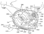
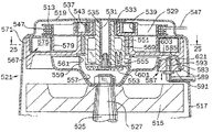
図24及び図25は、垂直なクランクシャフト525を持つ内燃エンジン521に適用した、本発明による第3のエンジン始動装置を示す。エンジン始動装置は、従来の巻き込みスターター513とクランクシャフト525の入力端527に回転自在に支持されたフライホイール515との間に取り付けられる。これに関し、エンジン始動装置は、本発明によるエンジン始動装置のオーバーザフライホイール(over−the−flywheel)態様と呼ぶことができる。
24 and 25 show a third engine starter according to the present invention applied to an
図24を参照すると、エンジン521は、エンジン始動装置及びフライホイール515を取り囲む下シュラウド517、及び巻き込みスターター513を実質的にカバーする上ハウジング519を含む。巻き込みスターター513は、駆動部材即ち駆動シャフト531を中心としてクラッチアッセンブリ533を介して回転自在に取り付けられた巻き込みスプール即ちプーリ529を含む。更に、下方に延びるスターターハブ535が、クラッチアッセンブリ533と駆動シャフト531との間で駆動シャフト531を中心として回転自在に取り付けられている。
Referring to FIG. 24, the
巻き込みプーリ529には、上方に面した溝即ち凹所537がクラッチアッセンブリ533の周囲に亘って形成されており、ここに巻き込みばね539が収容される。巻き込みばね539は、下方に延びる定置のフランジ543に一端が取り付けられており、巻き込みプーリ529に反対端が取り付けられている。更に、巻き込みプーリ529には周溝が設けられており、ここにコイル状スターターロープ547が保持される。スターターロープ547は、上ハウジング519の開口部(図示せず)を通って延びており、巻き込みプーリ529を時計廻り方向に回転するためにオペレータが引っ張ることができるハンドル端(図示せず)が設けられている。
In the winding
スターターハブ535は、駆動シャフト531の周囲で下方に延びており、巻き込みプーリ529の下に配置された半径方向に延びる下ハブ551を含む。オペレータブロック553がボルト止めされている。しかしながら、このブロックは駆動シャフト531の下部に対して及び下ハブ部分551と隣接して摩擦を伴って回転できる。従来と同様に、ばね賦勢された複数のクラッチドッグ555が下ハブ部分551内にオペレータブロック553と隣接して枢動自在に収容されている。スターターロープ547を引っ張ることによって巻き込みプーリ529を時計廻り方向に回転すると、クラッチドッグ555がオペレータブロック553によって半径方向外方に枢動される。
The
オペレータブロック553の下では、環状スターターカップ557がクランクシャフト525の入力端527にフライホイール515の上方で回転自在に取り付けられている。スターターカップ557は、入力端527から半径方向及び上方に延び、下ハブ部分551及びオペレータブロック553を取り囲む外リム部分559を含む。スターターカップ557の外リム部分559の内側には、実質的に半径方向に延びる衝合面561が設けられている。クラッチドッグ555を半径方向外方に枢動させる(即ちスターターロープ547を引っ張ることによって)と、クラッチドッグ555が衝合面561と係合し、スターターカップ557と回転係合する。
Under the
エンジン521の始動は、スターターロープ547を引っ張って巻き込みプーリ529を時計廻り方向に回転し、スターターハブ535を回転駆動することによって行われる。クラッチドッグ555は、スターターカップ557を時計廻り方向に回転駆動し、スターターカップ557はクランクシャフト525を時計廻り方向に駆動し、エンジン521を始動する。
The
図24及び図25の両方を参照すると、エンジン始動装置は、環状駆動ハウジング567(「ばねハウジング」)を含む。ばねハウジング567は、一方向クラッチアッセンブリ569を介してスターターハブ535の下ハブ部分551を中心として取り付けられる。ばねハウジング567は外周壁571を含み、この外周壁は、下方に延びる定置の支持フランジ579と関連して、ぜんまいばね575が保持される環状ケーシングを形成する。ぜんまいばね575又は変形例の弾性部材は、好ましくは、幅が約2.54cm(約1インチ)の金属バンドから形成される。図25に最もよく示すように、ぜんまいばね575の内端即ち縁部577は、定置フランジ579と係合できる。この際、ぜんまいばね575の外端581は、ばねハウジング567の外壁571に固定されている。変形例では、内端577は、本発明の第1実施例におけるのと同様に(例えば、図8参照)、アイレットを介して定置フランジ579と係合するようにループをなしているのがよい。
Referring to both FIGS. 24 and 25, the engine starter includes an annular drive housing 567 (“spring housing”). The
ぜんまいばね575は、ばねハウジング567を反時計廻り方向に回転することによって巻き上げることができる。一方向クラッチアッセンブリ569は、ばねハウジング567が時計廻り方向に回転する場合には、ばねハウジング567がスターターハブ535と回転係合できるが、ばねハウジング567が反時計廻り方向に回転するときには係合しないように設計されている。
The
ばねハウジング567は、外壁571から下方に延びる周囲フランジ583を含み、内方に面するテーパした表面585が形成されている。摩擦ローラー587がばねハウジング567と隣接して配置されている。摩擦ローラー587は、更に、好ましくはゴム材料から形成されたテーパした外面589、及び金属材料又はプラスチック材料から形成できるコア591を有する。摩擦ローラー587は、レバーアーム549に取り付けられたシャフト593に回転自在に取り付けられている。レバーアーム549は、エンジン521から遠隔に配置された制御アッセンブリ(図示せず)に相互連結されている。この制御アッセンブリは、レバーアーム549を操作して摩擦ローラー587をばねハウジング567に対して上下に移動するように作動できる。
エンジン始動装置は、クランクシャフト525の入力端527に回転自在に取り付けられたリワインドカップ601を更に含む。図24に示すように、リワインドカップ601は、スターターカップ557の外側で半径方向及び上方に延びており、実質的に軸線方向に延びるテーパした表面603を含む。テーパした表面603は、ばねハウジング567のテーパした表面585と鏡像対称をなしており、楔状凹所621をその間に形成する。
The engine starter further includes a
エンジンの作動状態中、及びエンジンのコーストダウン中、リワインドカップ601をクランクシャフト525によって時計廻り方向に回転させる。エンジンのコーストダウン中、摩擦ローラー587を上方に移動し、リワインドカップのテーパした表面603及びばねハウジングのテーパした表面585の両方と係合させる。従って、リワインドカップ601が摩擦ローラー587を反時計廻り方向に回転し、摩擦ローラー587がばねハウジング567を反時計廻り方向に回転。その結果、エンジンのコーストダウン中、クランクシャフト525が回転しているため、クランクシャフト525がぜんまいばね575を間接的に巻き上げる。
The
次に図25を参照すると、エンジン始動装置は、下シュラウド517の開口部605を通って延びるばね作動式ブレーキアッセンブリ607を含む。このアッセンブリは、ばねハウジング567の外壁571と隣接して取り付けられている。ブレーキアッセンブリ607は、枢動ポスト623に取り付けられており且つトーションばね613と係合する枢動自在のブラケット609を含む。トーションばね613は、ブラケット609を半径方向内方にばねハウジング567の外壁571に向かって押圧するように機能する。ブレーキアッセンブリ607は、更に、外壁571と摩擦係合可能な円弧状シュー615及びブラケット609のレバーアーム617に連結された制御ケーブル619を含む。
Referring now to FIG. 25, the engine starter includes a spring operated
本発明の一形態では、制御ケーブル619は、デッドマンハンドル(図示せず)に作動的に相互連結されている。デッドマンハンドルを押すと、制御ケーブル619がブラケット609を外方に枢動し、シュー615を外壁571から遠ざかる方向に引っ張る。逆に、デッドマンハンドルが解放されると、トーションばね613がブラケット609を内方に枢動し、シュー615が外壁571と摩擦係合する。その結果、ブレーキアッセンブリ607は、ばねハウジング567の時計廻り方向回転に抵抗し、停止する。
In one form of the invention, the
デッドマンハンドルが解放されると、ブレーキアッセンブリ607がばねハウジング567の外壁571と係合するのとほぼ同時に摩擦ローラー587が移動し、ばねリワインドカップ601とばねハウジング567との間に係合する。このようにして、エンジン始動装置は、フライホイール515、クランクシャフト525、及びエンジン521用のブレーキ機構としても作用する。変形例では、エンジン始動装置は、ブレーキアッセンブリ607がばねハウジング567の外壁571と係合する前に、先ず最初に摩擦ローラー587がばねリワインドカップ601とばねハウジング567とを相互連結するように作動するように設計される。この遅延により、ぜんまいばね575が一杯に巻き上げられるが、ブレーキアッセンブリは、ぜんまいばねの巻き過ぎが生じないように調時される。
When the deadman handle is released, the
次いでエンジン521を始動するため、デッドマンハンドルを押し、ブレーキアッセンブリ607及び摩擦ローラー587を夫々の摩擦係合位置から外す。その結果、巻き上げられたぜんまいばね575に蓄えられたエネルギが解放され、ばねハウジング567を時計廻り方向即ち始動方向(図25に矢印YYで示す方向)に回転する。更に、ばねハウジング567が一方向クラッチアッセンブリ569を駆動し、スターターハブ535を時計廻り方向即ち始動方向に回転する。更に、スターターハブ535の時計廻り方向回転により、スターターカップ557をクラッチドッグ555との係合によって回転駆動する。これによってクランクシャフト525を始動方向即ち時計廻り方向に回転する。
Next, in order to start the
エンジン始動装置のこの実施例の変形例では、巻き上げられたぜんまいばね575に蓄えられたエネルギは、巻き込みスタータープーリ529に対する動力補助として使用できる。巻き上げられたぜんまいばね575は、スターターロープ547に及ぼされる力の増大時に解放されるように設定できる。更に詳細には、スターターロープ547の力が所定レベル以下に低下すると、ブレーキアッセンブリ607が再度適用されてばねハウジング567を停止する。この場合、ぜんまいばね575に残るエネルギは、追加の始動の試みに使用できる。
In a variation of this embodiment of the engine starter, the energy stored in the
本発明の幾つかの実施例を示し且つ上文中に説明したが、本発明の所期の範囲内の変形例は、当業者に明らかであろう。従って、本発明は、特許請求の範囲のみによって限定される。 While several embodiments of the invention have been shown and described above, variations within the intended scope of the invention will be apparent to those skilled in the art. Accordingly, the invention is limited only by the following claims.
10 芝刈機
12 内燃エンジン
14 エンジン始動装置
18 ハンドルアッセンブリ
26 回転自在のエンジン部材
36、40 手動アクチュエータ
50 弾性部材
54 枢動自在のハウジング
56 入力エレメント
58,333 クラッチアッセンブリ
60 出力エレメント
122 制御ケーブル
607 ブレーキ
DESCRIPTION OF
Claims (11)
少なくとも一つの弾性部材を含むエネルギ蓄積機構、
前記弾性部材と係合でき、前記エンジンのコーストダウン中に前記回転自在のエンジン部材の回転に応じて移動して前記弾性部材に荷重を加える入力エレメント、及び
前記回転自在のエンジン部材を回転させるため、前記弾性部材の荷重解放に応じて移動できる出力エレメントを含む、エンジン始動装置。 An engine starter for an internal combustion engine having a rotatable engine member that can be rotated to start the engine,
An energy storage mechanism comprising at least one elastic member;
An input element that can be engaged with the elastic member and moves in accordance with the rotation of the rotatable engine member during coast down of the engine and applies a load to the elastic member; and the rotatable engine member is rotated. An engine starter comprising an output element that can move in response to a load release of the elastic member.
Applications Claiming Priority (1)
| Application Number | Priority Date | Filing Date | Title |
|---|---|---|---|
| US09/183,425 US6230678B1 (en) | 1998-10-30 | 1998-10-30 | Starting and stopping device for internal combustion engine |
Related Parent Applications (1)
| Application Number | Title | Priority Date | Filing Date |
|---|---|---|---|
| JP2000579888A Division JP3712615B2 (en) | 1998-10-30 | 1999-10-04 | Start / stop device for internal combustion engine |
Publications (1)
| Publication Number | Publication Date |
|---|---|
| JP2005299675A true JP2005299675A (en) | 2005-10-27 |
Family
ID=22672734
Family Applications (2)
| Application Number | Title | Priority Date | Filing Date |
|---|---|---|---|
| JP2000579888A Expired - Fee Related JP3712615B2 (en) | 1998-10-30 | 1999-10-04 | Start / stop device for internal combustion engine |
| JP2005154958A Withdrawn JP2005299675A (en) | 1998-10-30 | 2005-05-27 | Internal combustion engine starting/stopping device |
Family Applications Before (1)
| Application Number | Title | Priority Date | Filing Date |
|---|---|---|---|
| JP2000579888A Expired - Fee Related JP3712615B2 (en) | 1998-10-30 | 1999-10-04 | Start / stop device for internal combustion engine |
Country Status (8)
| Country | Link |
|---|---|
| US (5) | US6230678B1 (en) |
| EP (2) | EP1125059B1 (en) |
| JP (2) | JP3712615B2 (en) |
| CN (4) | CN1240938C (en) |
| AU (1) | AU747490B2 (en) |
| CA (1) | CA2347848A1 (en) |
| DE (2) | DE69934724T2 (en) |
| WO (1) | WO2000026531A1 (en) |
Families Citing this family (62)
| Publication number | Priority date | Publication date | Assignee | Title |
|---|---|---|---|---|
| US6647942B2 (en) | 1998-10-30 | 2003-11-18 | Briggs & Stratton Corporation | Engine starting and stopping device |
| US6325036B1 (en) * | 1998-10-30 | 2001-12-04 | Briggs & Stratton Corporation | Starting and stopping device for an internal combustion engine |
| US6595176B2 (en) | 1998-10-30 | 2003-07-22 | Briggs & Stratton Corporation | Engine starting and stopping device |
| US6615787B2 (en) | 1998-10-30 | 2003-09-09 | Briggs & Stratton Corporation | Engine starting and stopping device |
| US6622683B2 (en) | 1998-10-30 | 2003-09-23 | Briggs & Stratton Corporation | Engine starting and stopping device |
| AU2002232806A1 (en) * | 2000-10-20 | 2002-04-29 | Mtd Products Inc. | Apparatus and method for starting a mower engine |
| JP2002285940A (en) * | 2001-01-16 | 2002-10-03 | Kioritz Corp | Starter device |
| TW534954B (en) * | 2001-03-23 | 2003-06-01 | Ming-Huang Jiang | Auxiliary electrical generation system and device for engine |
| JP2003161238A (en) * | 2001-09-13 | 2003-06-06 | Denso Corp | Engine starter |
| US6644264B2 (en) * | 2001-10-22 | 2003-11-11 | Kohler Co. | Vertical shaft internal combustion engine with overhead power take-off |
| US6782863B2 (en) * | 2002-10-08 | 2004-08-31 | Mtd Products Inc. | Spring release starter |
| EP1422420B1 (en) * | 2002-11-25 | 2009-06-03 | Ford Global Technologies, LLC | Locking mechanism for the crankshaft of an internal combustion engine |
| USD488487S1 (en) | 2002-11-29 | 2004-04-13 | Maruyama Mfg. Co., Inc. | Machine to spray chemicals |
| JP4358609B2 (en) * | 2003-11-26 | 2009-11-04 | アルプス電気株式会社 | Electronic device operation device |
| US7654238B2 (en) * | 2004-11-08 | 2010-02-02 | Ford Global Technologies, Llc | Systems and methods for controlled shutdown and direct start for internal combustion engine |
| JP4376193B2 (en) * | 2005-02-08 | 2009-12-02 | ハスクバーナ・ゼノア株式会社 | Power transmission mechanism between engine starter and engine |
| US7267091B2 (en) * | 2005-04-27 | 2007-09-11 | Husqvarna Outdoor Products Inc. | Dynamic effortless pull starting |
| FR2891592B1 (en) * | 2005-10-03 | 2010-05-21 | Peugeot Citroen Automobiles Sa | MOTOR VEHICLE THERMAL MOTOR STARTER |
| CN101189427B (en) * | 2005-12-20 | 2011-08-17 | 富世华智诺株式会社 | Engine starting device |
| US7107960B1 (en) | 2005-12-22 | 2006-09-19 | Daimlerchrysler Corporation | Starter assist device for an engine |
| DE102007023225A1 (en) * | 2007-05-18 | 2008-11-20 | Bayerische Motoren Werke Aktiengesellschaft | Device and method for starting an internal combustion engine |
| DE102007032316B4 (en) * | 2007-07-11 | 2015-12-17 | Bayerische Motoren Werke Aktiengesellschaft | Vehicle with an energy recuperation and storage device |
| US7574988B1 (en) | 2008-03-17 | 2009-08-18 | Briggs And Stratton Corporation | Engine starter assembly |
| US8403102B2 (en) | 2008-07-07 | 2013-03-26 | Briggs & Stratton Corporation | Automatic engine speed adjustment |
| US8291879B2 (en) * | 2008-12-03 | 2012-10-23 | Techtronic Outdoor Products Technology Limited | Recoil starter system |
| US7762049B2 (en) * | 2008-12-31 | 2010-07-27 | Black & Decker Inc. | Electric mower having two-motion activation system |
| USD620029S1 (en) | 2009-09-11 | 2010-07-20 | Black & Decker Inc. | Mower |
| USD620030S1 (en) | 2009-09-11 | 2010-07-20 | Black & Decker Inc. | Mower |
| US20120073145A1 (en) * | 2010-09-24 | 2012-03-29 | Jan Gehrki | Weed trimmer with electrical starting mechanism |
| EP2693019B1 (en) * | 2011-03-31 | 2017-04-05 | Makita Corporation | Mobile operating machine having hybrid driving system |
| TWI413729B (en) * | 2011-08-26 | 2013-11-01 | Sanyang Industry Co Ltd | Engine flameout restart signal generation mechanism |
| US8727233B2 (en) | 2011-10-17 | 2014-05-20 | Champion Power Equipment, Inc. | Pressure spray washer and control |
| US8857138B2 (en) | 2011-11-04 | 2014-10-14 | Briggs & Stratton Corporation | Starter system for an engine |
| US9127658B2 (en) | 2011-11-04 | 2015-09-08 | Briggs & Stratton Corporation | Internal combustion engine including starting system powered by lithium-ion battery |
| US8733072B2 (en) | 2011-11-04 | 2014-05-27 | Briggs & Stratton Corporation | Starter system for an engine |
| CN103166536B (en) * | 2011-12-15 | 2018-01-16 | 德昌电机(深圳)有限公司 | Direct current starter and hay mover |
| CN102554348A (en) * | 2012-03-22 | 2012-07-11 | 彭桂华 | Dual-boot gasoline chain saw |
| AU2013249650B2 (en) * | 2012-04-17 | 2017-11-16 | Briggs & Stratton Corporation | Starter system for an engine |
| US9359988B2 (en) * | 2012-04-19 | 2016-06-07 | Kevin Lloyd McNabb | Direct current electric starter solenoid manual activation device |
| PL3295781T3 (en) | 2012-07-04 | 2022-12-12 | Husqvarna Ab | Robotic mower |
| USD692027S1 (en) * | 2013-01-30 | 2013-10-22 | The Toro Company | Push-button starter for a ground-working implement |
| US9847186B2 (en) | 2013-01-30 | 2017-12-19 | The Toro Company | Starter and power equipment unit incorporating same |
| US20140251267A1 (en) * | 2013-03-07 | 2014-09-11 | Ford Global Technologies, Llc | Method and system for improving engine starting |
| JP2014227932A (en) * | 2013-05-23 | 2014-12-08 | 昌毅 明石 | Idle stop and restart of internal combustion engine by spring |
| US10130962B2 (en) | 2013-10-10 | 2018-11-20 | Briggs & Stratton Corporation | Wirelessly controlled trigger start and chemical tank change-over for pressure washers |
| WO2015072900A1 (en) * | 2013-11-18 | 2015-05-21 | Husqvarna Ab | Starting device for an internal combustion engine |
| US9726135B2 (en) | 2014-02-21 | 2017-08-08 | Briggs & Stratton Corporation | Snowthrower with removable self-heating starter battery pack |
| CN106233494A (en) | 2014-03-06 | 2016-12-14 | 布里格斯和斯特拉顿公司 | For substituting the chargeable cell system of lead-acid battery |
| US9545054B2 (en) | 2014-10-22 | 2017-01-17 | Honda Motor Co., Ltd. | Mechanisms and related methods for drive by wire control systems in walk-behind working machines |
| CN107850031B (en) * | 2015-04-13 | 2020-07-07 | 慷市达汽车配件技术私人有限公司 | Arrangement of solenoid assembly with electronic switch for starter motor |
| FR3037360A1 (en) * | 2015-06-15 | 2016-12-16 | Christian Jean Felix Antoine Lafon | DEVICE FOR THE SMART STARTING OF SMALL INTERNAL COMBUSTION ENGINES BY STORING ENERGY IN THE VOLTAGE OF AN ELASTIC |
| USD795181S1 (en) | 2016-06-15 | 2017-08-22 | Briggs & Stratton Corporation | Battery |
| KR101872400B1 (en) * | 2017-01-20 | 2018-06-28 | 주식회사 나스켐 | Portable self-generation device and module including the same |
| JP2019044712A (en) * | 2017-09-04 | 2019-03-22 | ヤマハ発動機株式会社 | Outboard motor and engine starting device |
| JP2019138450A (en) * | 2018-02-15 | 2019-08-22 | 日本電産株式会社 | Speed reducer, motor unit, and cleaning robot |
| CN109025220B (en) * | 2018-08-03 | 2020-07-17 | 崇义县鑫晨商砼有限公司 | Concrete troweling machine with out-of-control centrifugal closing function |
| EP3854194A4 (en) * | 2018-11-20 | 2021-12-01 | Nanjing Chervon Industry Co., Ltd. | Hand-powered self-driven travelling machine |
| EP3744968B1 (en) * | 2019-05-28 | 2025-07-02 | Andreas Stihl AG & Co. KG | Spring box and manually-operated turning gear comprising such a spring box |
| JP7391357B2 (en) * | 2019-09-19 | 2023-12-05 | スターテング工業株式会社 | recoil starter |
| IT201900023511A1 (en) * | 2019-12-10 | 2021-06-10 | Stiga S P A In Breve Anche St S P A | Cutting blade height adjustment unit for a robotic lawnmower |
| US12279552B2 (en) | 2021-12-08 | 2025-04-22 | Honda Motor Co., Ltd. | Blade control assembly, lawnmower, and method for operating a blade control assembly |
| DK181366B1 (en) * | 2021-12-15 | 2023-09-08 | Fsi Power Tech Aps | Freewheel brake for garden/park equipment |
Family Cites Families (37)
| Publication number | Priority date | Publication date | Assignee | Title |
|---|---|---|---|---|
| US1009503A (en) | 1911-11-21 | Gavin Caird Goodhart | Self-starting device for internal-combustion engines. | |
| US932735A (en) | 1906-07-13 | 1909-08-31 | Arthur G Willard | Starting device for automobile and other engines. |
| US950848A (en) | 1909-07-12 | 1910-03-01 | Christopher Baldacci | Gasolene-engine starter. |
| US1022087A (en) | 1911-06-22 | 1912-04-02 | Charles D Jenney | Automobile-starter. |
| US1097899A (en) | 1911-09-22 | 1914-05-26 | Volkmar Auto Starter Company | Starter for internal-combustion engines. |
| US1137358A (en) | 1912-07-01 | 1915-04-27 | George B Sinclair | Starter for engines. |
| US1099685A (en) | 1913-08-30 | 1914-06-09 | Mogul Starter Company | Starting device for internal-combustion engines. |
| US1936554A (en) | 1931-02-18 | 1933-11-21 | Eclipse Aviat Corp | Spring starter |
| US2293322A (en) | 1940-04-17 | 1942-08-18 | William A Veach | Starter |
| US2922411A (en) | 1959-04-29 | 1960-01-26 | James L Skinner | Starter for motors |
| US3151605A (en) * | 1961-09-07 | 1964-10-06 | Toro Mfg Corp | Combined starter and engine control mechanism |
| US3301243A (en) * | 1963-09-09 | 1967-01-31 | Garland E Lyvers | Engine starting devices |
| US3165100A (en) | 1964-01-22 | 1965-01-12 | Briggs & Stratton Corp | Spring type starter for internal combustion engines |
| US3290871A (en) | 1964-07-20 | 1966-12-13 | Clinton Engines Corp | Emergency brake for internal combustion engine |
| US3324842A (en) | 1965-06-14 | 1967-06-13 | Clinton Engines Corp | Starting and braking means for internal combustion engines |
| US3375814A (en) | 1965-11-26 | 1968-04-02 | Eaton Stamping Co | Pulley construction for recoil starter |
| US3395687A (en) | 1967-03-20 | 1968-08-06 | Briggs & Stratton Corp | Automatic starter for small engines |
| US3447523A (en) * | 1967-05-12 | 1969-06-03 | Simms Motor Units Ltd | Starters for internal combustion engines |
| US3692010A (en) | 1970-11-27 | 1972-09-19 | Mcculloch Corp | Automatic system for spring starting an internal combustion engine |
| US3861374A (en) * | 1971-05-05 | 1975-01-21 | Mccullock Corp | Lightweight chain saw with engine restarting system and method and apparatus for restarting a warm internal combustion engine |
| US3853109A (en) | 1973-04-24 | 1974-12-10 | Mcculloch Corp | Method and apparatus starting an internal combustion engine |
| JPS5225941A (en) | 1975-08-25 | 1977-02-26 | Honda Motor Co Ltd | Engine starting device of autobicycle |
| GB1579237A (en) | 1976-03-24 | 1980-11-19 | Honda Motor Co Ltd | Engine starting device |
| US4104927A (en) | 1976-11-29 | 1978-08-08 | Jensen Jorn Benned | Engine starter |
| US4363298A (en) | 1980-12-18 | 1982-12-14 | Outboard Marine Corporation | Lawn mower brake and starter |
| IT1137110B (en) | 1981-03-31 | 1986-09-03 | Pirelli | ENERGY ACCUMULATOR AND STARTER FOR INTERNAL COMBUSTION ENGINES INCLUDING THE ACCUMULATOR |
| JPS5851271A (en) | 1981-09-19 | 1983-03-25 | Mitsubishi Heavy Ind Ltd | Power accumulating type automatic starting apparatus for internal-combustion engine |
| NL8501838A (en) | 1985-06-26 | 1987-01-16 | Stork Friesland Bv | SEMI-PERMEABLE MEMBRANES BASED ON SULPHONATE GROUPS CONTAINING POLYMERS. |
| FR2639677A1 (en) | 1988-11-29 | 1990-06-01 | Labourier Robert | Energy recovery device for restarting the engine of the vehicle |
| US5083534A (en) | 1989-04-05 | 1992-01-28 | Mitsubishi Jukogyo Kabushiki Kaisha | Spiral spring type starter apparatus for an internal combustion engine |
| US4979596A (en) * | 1989-06-27 | 1990-12-25 | Tecumseh Products Company | Safety brake system for an engine |
| US5086890A (en) | 1990-03-14 | 1992-02-11 | Briggs & Stratton Corporation | Engine braking system |
| JPH07174061A (en) | 1993-05-07 | 1995-07-11 | Nitsukari:Kk | Force storage type recoil starter |
| JP3328753B2 (en) | 1993-12-22 | 2002-09-30 | フジオーゼックス株式会社 | Fe-based alloy composition for cladding |
| US5431135A (en) | 1994-04-28 | 1995-07-11 | Eaton Stamping Company | Starter assembly |
| US5596902A (en) * | 1994-11-15 | 1997-01-28 | United Technologies Motor Systems, Inc. | Starter drive clutch |
| GB9503488D0 (en) | 1995-02-22 | 1995-04-12 | Pentham Ltd | Pentham starter |
-
1998
- 1998-10-30 US US09/183,425 patent/US6230678B1/en not_active Expired - Fee Related
-
1999
- 1999-10-04 EP EP99954726A patent/EP1125059B1/en not_active Expired - Lifetime
- 1999-10-04 AU AU11008/00A patent/AU747490B2/en not_active Ceased
- 1999-10-04 JP JP2000579888A patent/JP3712615B2/en not_active Expired - Fee Related
- 1999-10-04 DE DE69934724T patent/DE69934724T2/en not_active Expired - Fee Related
- 1999-10-04 CA CA002347848A patent/CA2347848A1/en not_active Abandoned
- 1999-10-04 CN CNB021479070A patent/CN1240938C/en not_active Expired - Fee Related
- 1999-10-04 CN CNB021479089A patent/CN1268841C/en not_active Expired - Fee Related
- 1999-10-04 DE DE69919564T patent/DE69919564T2/en not_active Expired - Fee Related
- 1999-10-04 CN CNB021479062A patent/CN1268840C/en not_active Expired - Fee Related
- 1999-10-04 CN CN99810843A patent/CN1128927C/en not_active Expired - Fee Related
- 1999-10-04 WO PCT/US1999/023046 patent/WO2000026531A1/en not_active Ceased
- 1999-10-04 EP EP03019891A patent/EP1365144B1/en not_active Expired - Lifetime
-
2000
- 2000-11-10 US US09/709,859 patent/US6386169B1/en not_active Expired - Fee Related
-
2001
- 2001-02-09 US US09/780,219 patent/US6263852B1/en not_active Expired - Fee Related
- 2001-02-09 US US09/780,108 patent/US6260529B1/en not_active Expired - Fee Related
- 2001-02-09 US US09/780,109 patent/US6311663B2/en not_active Expired - Fee Related
-
2005
- 2005-05-27 JP JP2005154958A patent/JP2005299675A/en not_active Withdrawn
Also Published As
| Publication number | Publication date |
|---|---|
| DE69919564D1 (en) | 2004-09-23 |
| EP1365144B1 (en) | 2007-01-03 |
| JP2002529643A (en) | 2002-09-10 |
| US6386169B1 (en) | 2002-05-14 |
| CN1268841C (en) | 2006-08-09 |
| US20010008130A1 (en) | 2001-07-19 |
| AU1100800A (en) | 2000-05-22 |
| DE69919564T2 (en) | 2005-09-15 |
| EP1365144A2 (en) | 2003-11-26 |
| DE69934724T2 (en) | 2007-10-18 |
| CN1268840C (en) | 2006-08-09 |
| WO2000026531A1 (en) | 2000-05-11 |
| JP3712615B2 (en) | 2005-11-02 |
| US20010006051A1 (en) | 2001-07-05 |
| EP1125059B1 (en) | 2004-08-18 |
| CN1515795A (en) | 2004-07-28 |
| US20010006052A1 (en) | 2001-07-05 |
| CN1240938C (en) | 2006-02-08 |
| EP1125059A1 (en) | 2001-08-22 |
| US6230678B1 (en) | 2001-05-15 |
| US6263852B1 (en) | 2001-07-24 |
| CN1492141A (en) | 2004-04-28 |
| US6311663B2 (en) | 2001-11-06 |
| CA2347848A1 (en) | 2000-05-11 |
| US6260529B1 (en) | 2001-07-17 |
| CN1318134A (en) | 2001-10-17 |
| EP1365144A3 (en) | 2004-11-24 |
| AU747490B2 (en) | 2002-05-16 |
| CN1515796A (en) | 2004-07-28 |
| DE69934724D1 (en) | 2007-02-15 |
| CN1128927C (en) | 2003-11-26 |
Similar Documents
| Publication | Publication Date | Title |
|---|---|---|
| JP3712615B2 (en) | Start / stop device for internal combustion engine | |
| EP1311757B1 (en) | Starting and stopping device for an internal combustion engine | |
| US6834633B2 (en) | Spring release starter for chain saw | |
| JPH07174061A (en) | Force storage type recoil starter | |
| EP1407138B1 (en) | Engine starting and stopping device | |
| US2804173A (en) | Turning device for rotatable body | |
| US6595176B2 (en) | Engine starting and stopping device | |
| US6615787B2 (en) | Engine starting and stopping device | |
| US20020023608A1 (en) | Engine starting and stopping device | |
| US2922411A (en) | Starter for motors | |
| US3081760A (en) | Spring starter | |
| US2999490A (en) | Spring starter |
Legal Events
| Date | Code | Title | Description |
|---|---|---|---|
| A761 | Written withdrawal of application |
Free format text: JAPANESE INTERMEDIATE CODE: A761 Effective date: 20070208 |
|
| A521 | Request for written amendment filed |
Free format text: JAPANESE INTERMEDIATE CODE: A821 Effective date: 20070208 |