JP2005299628A - Filter regeneration control device for diesel engine - Google Patents
Filter regeneration control device for diesel engine Download PDFInfo
- Publication number
- JP2005299628A JP2005299628A JP2004204211A JP2004204211A JP2005299628A JP 2005299628 A JP2005299628 A JP 2005299628A JP 2004204211 A JP2004204211 A JP 2004204211A JP 2004204211 A JP2004204211 A JP 2004204211A JP 2005299628 A JP2005299628 A JP 2005299628A
- Authority
- JP
- Japan
- Prior art keywords
- air
- intake
- filter
- diesel engine
- air duct
- Prior art date
- Legal status (The legal status is an assumption and is not a legal conclusion. Google has not performed a legal analysis and makes no representation as to the accuracy of the status listed.)
- Pending
Links
Images
Classifications
-
- Y—GENERAL TAGGING OF NEW TECHNOLOGICAL DEVELOPMENTS; GENERAL TAGGING OF CROSS-SECTIONAL TECHNOLOGIES SPANNING OVER SEVERAL SECTIONS OF THE IPC; TECHNICAL SUBJECTS COVERED BY FORMER USPC CROSS-REFERENCE ART COLLECTIONS [XRACs] AND DIGESTS
- Y02—TECHNOLOGIES OR APPLICATIONS FOR MITIGATION OR ADAPTATION AGAINST CLIMATE CHANGE
- Y02T—CLIMATE CHANGE MITIGATION TECHNOLOGIES RELATED TO TRANSPORTATION
- Y02T10/00—Road transport of goods or passengers
- Y02T10/10—Internal combustion engine [ICE] based vehicles
- Y02T10/12—Improving ICE efficiencies
Landscapes
- Combined Controls Of Internal Combustion Engines (AREA)
- Processes For Solid Components From Exhaust (AREA)
- Electrical Control Of Air Or Fuel Supplied To Internal-Combustion Engine (AREA)
Abstract
【課題】DPFの再生時間を短縮するとともに燃費の向上をも図ることができるフィルタ再生制御装置を提供する。
【解決手段】ディーゼル機関の排気系に設けられ、排ガス中のパティキュレートを捕捉するフィルタ12と、フィルタの再生時期を検出する検出手段21と、フィルタの再生時期を検出したらポスト噴射を行ってフィルタの温度を上昇させて堆積しているパティキュレートを燃焼させる制御手段30とを備えるディーゼル機関のフィルタ再生制御装置であって、排気系の熱によって加熱された空気を通流可能なホットエアダクト14と、外気を通流可能な新気ダクト2と、ディーゼル機関の吸気系にホットエアダクト及び新気ダクトに連通して設けられ、ホットエアダクト又は新気ダクトから吸入する空気を切り替える吸気切替手段3とを備え、フィルタを再生するときにホットエアダクトから加熱空気を吸入するようにした。
【選択図】図1A filter regeneration control device capable of shortening the regeneration time of a DPF and improving fuel consumption is provided.
A filter provided in an exhaust system of a diesel engine for capturing particulates in exhaust gas, a detecting means for detecting a regeneration time of the filter, and a post-injection when the regeneration time of the filter is detected. A filter regeneration control device for a diesel engine comprising a control means 30 for burning the accumulated particulates by raising the temperature of the hot air duct 14 capable of passing air heated by heat of the exhaust system; A fresh air duct 2 through which outside air can flow, and an intake air switching means 3 provided in communication with the hot air duct and the fresh air duct in the intake system of the diesel engine, and for switching the air sucked from the hot air duct or the fresh air duct. In order to regenerate the filter, heated air was sucked from the hot air duct.
[Selection] Figure 1
Description
本発明は、ディーゼル機関の排ガス浄化対策として使用するフィルタを再生する制御装置に関するものである。 The present invention relates to a control device for regenerating a filter used as an exhaust gas purification measure for a diesel engine.
ディーゼルエンジンでは、従来から排ガスの浄化対策として排気管の途中にPM(Particulate Matter:粒子状物質)を捕捉するDPF(diesel Particulate Filter)を装備している。この種のDPFは、コージェライト等のセラミックから成る多孔質のハニカム構造となっており、格子状に区画された各流路の入口が交互に目封じされ、入口が目封じされていない流路については、その出口が目封じされるようになっており、各流路を区画する多孔質薄壁を透過した排ガスのみが下流側へ排出されるようにしてある。この多孔質薄壁の内側表面で排ガス中のPMを捕捉し堆積する。この堆積量が増大しすぎては目詰まりを生じてしまうので、適宜PMを燃焼除去してDPFを再生する必要がある。 Conventionally, a diesel engine is equipped with a DPF (diesel particulate filter) that traps PM (particulate matter) in the middle of an exhaust pipe as a measure for purifying exhaust gas. This type of DPF has a porous honeycomb structure made of ceramics such as cordierite, and the inlets of the respective channels partitioned in a lattice pattern are alternately sealed, and the channels are not sealed. The outlet is sealed, and only the exhaust gas that has permeated through the porous thin wall partitioning each flow path is discharged downstream. The PM in the exhaust gas is captured and deposited on the inner surface of the porous thin wall. If this amount of deposition increases too much, clogging will occur, so it is necessary to regenerate the DPF by burning off PM as appropriate.
例えば、特許文献1では、アルミナに白金を担持させ、さらに適宜な量のセリウム等の希土類元素を添加した酸化触媒を一体的に担持させたDPFを使用している。このようにすると、捕捉したPMの酸化反応が促進されて着火温度が低下する。そのため、従来よりも低い排気温度でPMを燃焼除去することが可能になる。そして、エンジンから排出された直後の排ガスの熱を、ヒートパイプでDPFのすぐ上流に伝導するようにすることで、PMを燃焼除去してDPFを再生している。
しかし、前述した従来装置は、排気管をバイパスするヒートポンプを設けることで、エンジンから排出された直後の排ガスの熱をDPFのすぐ上流に伝導するようにしているが、その効果は排気管途中での排気温度の低下を減少させるのにとどまるので、DPF再生という効果はそれほど大きいものではなかった。 However, the above-described conventional apparatus is configured to conduct the heat of the exhaust gas immediately after being exhausted from the engine immediately upstream of the DPF by providing a heat pump that bypasses the exhaust pipe. Therefore, the effect of DPF regeneration was not so great.
本発明は、このような従来の問題点に着目してなされたものであり、DPFの再生時間を短縮するとともに燃費の向上をも図ることができるフィルタ再生制御装置を提供することを目的としている。 The present invention has been made paying attention to such conventional problems, and an object of the present invention is to provide a filter regeneration control device capable of shortening the regeneration time of the DPF and improving the fuel consumption. .
本発明は以下のような解決手段により前記課題を解決する。なお、理解を容易にするために本発明の実施形態に対応する符号を付するが、これに限定されるものではない。 The present invention solves the above problems by the following means. In addition, in order to make an understanding easy, although the code | symbol corresponding to embodiment of this invention is attached | subjected, it is not limited to this.
本発明は、ディーゼル機関の排気系に設けられ、排ガス中のパティキュレートを捕捉するフィルタ(12)と、前記フィルタの再生時期を検出する検出手段(21)と、前記フィルタの再生時期を検出したらポスト噴射を行って前記フィルタの温度を上昇させて堆積しているパティキュレートを燃焼させる制御手段(30)とを備えるディーゼル機関のフィルタ再生制御装置であって、排気系の熱によって加熱された空気を通流可能なホットエアダクト(14)と、外気を通流可能な新気ダクト(2)と、前記ディーゼル機関の吸気系に前記ホットエアダクト及び前記新気ダクトに連通して設けられ、前記ホットエアダクト又は前記新気ダクトから吸入する空気を切り替える吸気切替手段(3)とを備え、前記フィルタを再生するときに前記ホットエアダクトから加熱空気を吸入するようにしたことを特徴とする。 The present invention provides a filter (12) provided in an exhaust system of a diesel engine for capturing particulates in exhaust gas, a detection means (21) for detecting the regeneration time of the filter, and a regeneration time of the filter. A filter regeneration control device for a diesel engine, comprising control means (30) for performing post-injection to raise the temperature of the filter and combusting accumulated particulates, wherein the air is heated by the heat of the exhaust system A hot air duct (14) capable of flowing through, a fresh air duct (2) capable of flowing outside air, and an intake system of the diesel engine provided in communication with the hot air duct and the fresh air duct. An air intake switching means (3) for switching air taken in from the air duct or the fresh air duct, and when regenerating the filter, Characterized in that so as to intake the hot air from Ttoeadakuto.
本発明によれば、フィルタを再生するときにホットエアダクトから加熱空気を吸入するようにしたので、排気温度が上昇しポスト噴射を低減することができる。そのため燃費が向上する。またフィルタの再生時間の短縮化を図ることができる。 According to the present invention, since the heated air is sucked from the hot air duct when the filter is regenerated, the exhaust temperature rises and post injection can be reduced. Therefore, fuel consumption is improved. In addition, the filter regeneration time can be shortened.
以下、図面等を参照して本発明の実施の形態についてさらに詳しく説明する。
(第1実施形態)
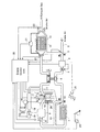
図1は本発明によるDPF再生制御装置の第1実施形態を示す図である。
Hereinafter, embodiments of the present invention will be described in more detail with reference to the drawings.
(First embodiment)
FIG. 1 is a diagram showing a first embodiment of a DPF regeneration control apparatus according to the present invention.
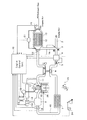
はじめにDPF再生制御装置1の構成について説明する。DPF12は酸化触媒を一体的に担持したタイプのものであり、HC(Hydro Carbon)を酸化(燃焼)可能である。DPF12の周囲には、周辺部品に対する熱影響(熱害)を防止するための遮熱板13が設けられている。そのDPF12及び遮熱板13のあいだの空間から外気を吸入可能であり、その吸入された空気はホットエアダクト14に通流する。
First, the configuration of the DPF
吸気切替弁3は、開閉してホットエアダクト14及び新気ダクト2から吸入する空気を切り替える。吸気切替弁3が開弁するとホットエアダクト14からの空気を吸入する。吸気切替弁3が閉弁すると新気ダクト2から空気を吸入する。
The intake
吸入された空気は、エアクリーナ4で清浄され、エアフローメータ5で吸入量が検出され、ターボチャージャ6で過給され、インタークーラ7で冷却され、インテークシャッタ8、インテークマニホールド9を通流してエンジン本体10に吸入される。その空気に対して、燃料ポンプ15からコモンレール16に供給された燃料がインジェクションノズル17から噴射される。すると着火して、燃焼ガスがエキゾーストマニホールド11から排気される。そして、その燃焼ガス中のPM(煤)がDPF12でトラップ(堆積)される。なお、燃焼ガスの一部は、エキゾーストマニホールド11から、EGRクーラ18、EGRバルブ19を通流してインテークマニホールド9に還流される。
The sucked air is cleaned by the air cleaner 4, the suction amount is detected by the
DPF12の入口と出口との圧力差は差圧センサ21で検出される。また、DPF12の入口温度はDPF入口温度センサ22で検出され、出口温度はDPF出口温度センサ23で検出される。24はスロットルポジションセンサであり、アクセル踏込量を検出する。25はエンジン本体10のクランク軸の回転速度を検出するクランク角センサである。26はエンジン本体10の水温を検出する水温センサである。それらセンサの検出信号はエンジンコントロールユニット30に送られる。
The pressure difference between the inlet and the outlet of the
次にエンジンコントロールユニット30の制御内容について説明する。
Next, the control content of the
上述のように、DPF12は、燃焼ガス中のPM(煤)をトラップ(堆積)する。その堆積量が増大しすぎると目詰まりを生じて排気抵抗が増加してしまうので、堆積しているPM(煤)を適宜燃焼除去して再生を図る必要がある。DPFを再生するときはDPFを高温にする必要がある。
As described above, the
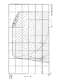
従来は、予備実験に基づき作成した図3のような制御マップを参照して制御していた。具体的には、領域Iではインジェクションタイミングを遅らすことで(以下「ITリタード」という)、排気温度を上げ、DPFを高温にしてPMを燃焼していた。領域IIでは通常の燃料噴射後にさらに燃料を噴射していた(以下「ポスト噴射」という)。このとき発生したHCは酸化触媒で燃焼し、その熱でPMも燃焼する。さらに、領域IIIではポスト噴射に加えて吸気を絞る。するとエンジンは吸入空気を吸う仕事を行い、それによっても発熱量が増大し、DPFが高温になってPMが燃焼する。なお領域IVは排気温度がPM燃焼温度に達しているので特別な制御を必要としない領域である。 Conventionally, control is performed with reference to a control map as shown in FIG. 3 created based on a preliminary experiment. More specifically, in region I, the injection timing was delayed (hereinafter referred to as “IT retard”), the exhaust temperature was raised, the DPF was raised, and PM was burned. In area II, further fuel was injected after normal fuel injection (hereinafter referred to as “post injection”). The HC generated at this time is burned by the oxidation catalyst, and the PM is burned by the heat. Further, in region III, the intake air is throttled in addition to the post injection. The engine then performs the work of sucking in the intake air, which also increases the amount of heat generation, the DPF becomes high temperature, and PM burns. Region IV is a region where no special control is required because the exhaust gas temperature reaches the PM combustion temperature.
しかし、このようにすることでDPFを再生できるが、燃料の消費量が増すので、できる限り行わないことが望ましい。 However, although DPF can be regenerated by doing in this way, it is desirable not to perform it as much as possible because the amount of fuel consumption increases.
ところで、エンジンの吸気温度を上げれば排気温度が上がる。したがって、あらかじめ加熱した空気を供給すれば排気温度を上昇させることができる。この性質を利用すれば、ポスト噴射量を軽減することができる。 By the way, if the intake temperature of the engine is raised, the exhaust temperature will rise. Therefore, the exhaust temperature can be raised by supplying preheated air. By utilizing this property, the post injection amount can be reduced.
本発明者は、排気系の熱を利用することに着目した。特にDPFは再生時に高温になる。そこでDPFの放熱によって加熱された空気をエンジンに吸気することで、排気温度を上昇させるようにしたのである。ただし、高温の空気は密度が低いので充填効率が悪化する。そこで、平坦路を一定速度で走行しているときのような低負荷運転時では加熱空気を吸気し、加速時のような高負荷運転時では加熱していない通常の空気を吸気するようにした。なお以下の実施形態では特にDPFの放熱によって加熱された空気を吸気する場合を例示して説明しているが、DPF以外の排気系の放熱で加熱された空気を吸気してもよい。 The present inventor has focused on utilizing the heat of the exhaust system. In particular, DPF becomes hot during regeneration. Therefore, the exhaust air temperature is raised by sucking the air heated by the heat radiation of the DPF into the engine. However, since high-temperature air has a low density, filling efficiency deteriorates. Therefore, heated air is sucked during low-load operation such as when driving on a flat road at a constant speed, and normal unheated air is sucked during high-load operation such as acceleration. . In the following embodiments, the case where air heated by heat radiation of the DPF is sucked in particular is described as an example. However, air heated by heat radiation of an exhaust system other than the DPF may be sucked.
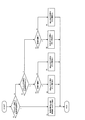
以下、コントロールユニット60の具体的な制御ロジックについて図2のフローチャートに沿って説明する。 Hereinafter, specific control logic of the control unit 60 will be described with reference to the flowchart of FIG.
DPFの再生時期を検知したら処理を開始する。なおDPFを再生しないときは吸気切替弁3を閉弁しておき、従来と同様に制御する。なおDPFの再生時期の検知方法としては、例えば差圧センサ21でDPF12の入口部分と出口部分との圧力差を検知し、その差圧がある基準圧よりも大きくなったらDPF12の詰まりが発生しており再生時期であると判定する。また基準時間の経過をもって再生時期と判定してもよい。
When the DPF regeneration time is detected, the processing is started. When the DPF is not regenerated, the
ステップS1では、DPF12の入口部分の温度が、酸化触媒の活性化温度(以下「触媒活性温度」という)以下であるか否かを判定する。この触媒活性温度は、具体的には機関の特性や運転条件等に基づいて決めればよいが、一例を挙げるならば250℃程度である。
In step S1, it is determined whether or not the temperature of the inlet portion of the
触媒活性温度以下のときは(ステップS1でY)、ステップS2に進み、少しでも温度を上げるために吸気切替弁3を開弁してDPF12で加熱された高温空気を吸気する。また、吸気を絞ってエンジンに吸入空気を吸う仕事を行わせることで発熱させる。さらにポスト噴射を行ってHCの着火によるDPF12の高温化を図る。
When the temperature is equal to or lower than the catalyst activation temperature (Y in Step S1), the process proceeds to Step S2, and in order to raise the temperature as much as possible, the
触媒活性温度を上回るときは(ステップS1でN)、さらにステップS3においてDPF12の入口部分の温度がPMの燃焼温度以上であるか否かを判定する。このPM燃焼温度も具体的には機関の特性や運転条件等に基づいて決めればよいが、一例を挙げるならば650℃程度である。
When the temperature exceeds the catalyst activation temperature (N in step S1), it is further determined in step S3 whether or not the temperature of the inlet portion of the
PM燃焼温度未満のときは(ステップS3でN)、次にステップS4で低負荷運転であるか否かを判定する。低負荷運転とは、例えば、平坦路を一定速度で走行している場合などであり、このときエンジンは大きな出力は要求されない。なおこの判定はアクセル踏込量(スロットルポジションセンサ24の信号)によって判定可能である。このときはステップS5へ進んで吸気切替弁3を開弁してDPF12の放熱によって加熱された空気を吸気することで、排気温度を上げる。するとDPF12の温度が迅速に上昇する。またポスト噴射を行う。このようにポスト噴射を行うと、排ガス中にはHCが含有されることとなり、そのHCがDPF12に担持されている酸化触媒で酸化(燃焼)してDPF12の高温化を図ることができる。なお、加熱空気を吸気することで排気温度が上昇するので、加熱空気を吸気しない場合に比べてポスト噴射量を低減可能である。
When the temperature is lower than the PM combustion temperature (N in Step S3), it is next determined in Step S4 whether or not the low load operation is being performed. The low load operation is, for example, a case where the vehicle is traveling on a flat road at a constant speed, and at this time, the engine does not require a large output. This determination can be made based on the accelerator depression amount (a signal from the throttle position sensor 24). At this time, the routine proceeds to step S5, where the intake
一方、高負荷運転とは、例えば登坂路を走行している場合や加速している場合などであり、このときエンジンは大きな出力が要求される。このときはステップS6へ進んで吸気切替弁3を閉弁して、加熱空気の吸気を止め、新気ダクト2からの吸気を図ることで、空気の充填効率を下げないようにしながら、ポスト噴射を行う。
On the other hand, the high-load operation is, for example, when traveling on an uphill road or accelerating, and at this time, the engine is required to have a large output. At this time, the routine proceeds to step S6, the
ステップS3において、DPF12の入口部分の温度がPM燃焼温度以上であると判定したときは、ステップS7において低負荷運転か否かを判定し、低負荷運転のときは、ステップS8へ進んで吸気切替弁3を開弁してDPF12の放熱によって加熱された空気を吸気することで、排気温度を上げ、DPF12の温度を迅速に上昇させることでDPF12の再生時間の短時間化を図る。なおこのときはDPF12の内部温度がすでにPMの燃焼温度に達しているので、ポスト噴射を行う必要はない。一方、高負荷運転のときは、ステップS9へ進んで吸気切替弁3を閉弁して、加熱空気の吸気を止め、新気ダクト2からの吸気を図ることで、空気の充填効率を下げないようにする。
In step S3, when it is determined that the temperature of the inlet portion of the
続いて本実施形態の効果を説明する。 Then, the effect of this embodiment is demonstrated.
本実施形態によれば、DPF12を再生するときは吸気切替弁3を開弁してDPF12の放熱によって加熱した空気を吸気するようにした。これにより排気温度を上げることができるので、ポスト噴射を低減することができる。したがって燃費が向上する。またDPF12の再生時間の短縮化を図ることができる。
According to the present embodiment, when the
また、機関負荷が高いときは吸気切替弁3を閉弁して新気ダクト2から吸気するようにした。このようにしたので、空気の充填効率を下げず、高出力を得ることができる。なお高負荷のときは高速時でもあることから走行風が多く、熱害を生じにくい状況になっている。
Further, when the engine load is high, the intake
さらに、DPF12の入口部分の温度がPM燃焼温度以上のときはポスト噴射を行わないようにしたので燃費の向上を図ることができる。
Further, since the post-injection is not performed when the temperature of the inlet portion of the
さらにまた、DPF12と遮熱板13とのあいだでDPF12の放熱によって加熱された空気を吸気するようにしたので、DPF12の周辺部品に対する熱影響(熱害)を低減することができる。
Furthermore, since the air heated by the heat radiation of the
なお、本実施形態では、機関負荷が高いときは新気ダクトから吸気するが、通常、DPFの再生は主に低負荷で行うので、ほとんどの場合は吸気切替弁3を開弁してホットエアダクト14から吸気することとなり、ポスト噴射を低減することによる燃費の向上という効果が非常に大きいのである。
In this embodiment, when the engine load is high, the intake air is taken in from the fresh air duct. Usually, however, the regeneration of the DPF is mainly performed at a low load, so in most cases, the intake
(第2実施形態)
上記第1実施形態では、DPF再生時に排気温度を上昇させるために、吸気切替弁3を開弁して、DPF12の放熱によって加熱された空気をホットエアダクト14から吸入している。しかし、インタークーラ7によってエンジンの吸気温度を低下させるので、排気温度の上昇効果が低下してしまう。
(Second Embodiment)
In the first embodiment, in order to raise the exhaust temperature during DPF regeneration, the intake
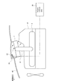
そこで、本実施形態では、インタークーラ7に通流する冷却風を調整するインタークーラシャッタ42を設け、DPF再生時で排気温度を上昇させる必要があるときには、インタークーラシャッタ42を閉じるようにした。このようにすることで、インタークーラ7に通流する冷却風を低減させることができ、排気温度の上昇効果を一層向上させることができるのである。以下では図4のエンジンルームの側面模式図を参照して具体的な構成について説明する。なお以下では前述した実施形態と同様の機能を果たす部分には同一の符号を付して重複する説明を適宜省略する。
Therefore, in the present embodiment, the
インタークーラ7は、フード43に形成された冷却風取入口44の下方に配置されている。インタクーラ7へはターボチャージャ6で過給された空気が流入する。そしてその吸気はインタクーラ7から、吸気通路41を介してインテークマニホールド9を通流してエンジン本体10に吸入される。
The
そして、冷却風取入口44にはインタークーラシャッタ42が設けられている。このインタークーラシャッタ42はエンジンコントロールユニット30によって開閉状態が制御される。なお図4中、一点破線が制御線であり、エンジンコントロールユニット30に接続される。図4の破線に示すようにインタークーラシャッタ42が開いたときには、破線矢印のように冷却風がインタクーラ7を通流し、ターボチャージャ6で過給された吸気を冷却する。一方、図4の実線に示すようにインタークーラシャッタ42が閉じたときには、冷却風はインタクーラ7を通流しないので、ターボチャージャ6で過給された吸気は冷却されない。
An
そして本実施形態では、インタークーラシャッタ42の開閉は、吸気切替弁3の開閉と同期するようにした。すなわち、吸気切替弁3を開弁してホットエアダクト14からの空気を吸入するときには、インタークーラシャッタ42を閉じて、吸気を冷却しないようにした。一方、吸気切替弁3を閉弁して新気ダクト2からの空気を吸入するときには、インタークーラシャッタ42を開いて、吸気を冷却するようにした。
In the present embodiment, the opening / closing of the
このようにすることで、DPF再生時に加熱した外気を吸入するときに、インタークーラシャッタ42を閉じるので、加熱された吸気がインタークーラ7を通過するときの放熱量が減少し、吸気の温度低下が少なくなり、排気温度が上昇し、低負荷時のDPF再生が容易になる。
By doing so, the
(第3実施形態)
本発明によるDPF再生制御装置の第3実施形態を示す図である。
(Third embodiment)
It is a figure which shows 3rd Embodiment of the DPF regeneration control apparatus by this invention.
本実施形態のフィルタ再生制御装置は、バイパス通路51と、流路切替弁52とを有する。
The filter regeneration control device of this embodiment includes a
バイパス通路51は、インタークーラ7の上流側の吸気通路と下流側の吸気通路を連通するように形成され、ターボチャージャ6で過給された吸気がインタークーラ7を迂回可能な通路である。
The
流路切替弁52は、ターボチャージャ6で過給された吸気がインタークーラ7又はバイパス通路51に通流するように流路を切り替える。流路切替弁51が閉弁すると吸気はインタークーラ7に通流する。流路切替弁52が開弁すると吸気はインタークーラ7をバイパスしてバイパス通路51を通流する。
The flow path switching valve 52 switches the flow path so that the intake air supercharged by the turbocharger 6 flows through the
流路切替弁52の開閉は、吸気切替弁3の開閉と同期するようにした。すなわち、吸気切替弁3を開弁してホットエアダクト14からの空気を吸入するときには、流路切替弁52を開いて、ターボチャージャ6で過給された吸気をバイパス通路51に通流させ、インタークーラ7に通流しないようにする。一方、吸気切替弁3を閉弁して新気ダクト2からの空気を吸入するときには、流路切替弁52を閉じて、ターボチャージャ6で過給された吸気をインタークーラ7に通流させて冷却するようにした。
The opening / closing of the flow path switching valve 52 is synchronized with the opening / closing of the
このようにしても、DPF再生時に吸入して加熱した吸気をバイパス通路51を通流させてインタークーラ7で冷却しないようにしたので、吸気の温度低下が少なくなり、排気温度が上昇し、低負荷時のDPF再生が容易になる。
Even in this case, since the intake air sucked and heated during the regeneration of the DPF is flown through the
以上説明した実施形態に限定されることなく、その技術的思想の範囲内において種々の変形や変更が可能であり、それらも本発明と均等であることは明白である。 The present invention is not limited to the embodiment described above, and various modifications and changes can be made within the scope of the technical idea, and it is obvious that these are equivalent to the present invention.
例えば、上記実施形態においては、DPFと、その周囲に取り付けられた遮熱板とのあいだから加熱空気を吸気することとしているが、DPF以外の排気系の放熱で加熱された空気を吸気してもよい。 For example, in the above embodiment, the heated air is sucked in between the DPF and the heat shield attached around the DPF. However, the heated air is sucked by the heat radiation of the exhaust system other than the DPF. Also good.
1 DPF再生制御装置
2 新気ダクト
3 吸気切替弁(吸気切替手段)
7 インタークーラ
10 エンジン本体
12 DPF(フィルタ)
13 遮熱板
14 ホットエアダクト
21 差圧センサ(フィルタ再生時期検出手段)
22 DPF入口温度センサ
24 スロットルポジションセンサ
30 エンジンコントロールユニット(制御手段)
42 インタークーラシャッタ(吸気冷却抑制手段)
44 冷却風取入口
51 バイパス通路
52 流路切替弁(吸気冷却抑制手段)
1 DPF
7
13
22 DPF
42 Intercooler shutter (intake air cooling suppression means)
44
Claims (7)
前記フィルタの再生時期を検出する検出手段と、
前記フィルタの再生時期を検出したらポスト噴射を行って前記フィルタの温度を上昇させて堆積しているパティキュレートを燃焼させる制御手段と、
を備えるディーゼル機関のフィルタ再生制御装置であって、
排気系の熱によって加熱された空気を通流可能なホットエアダクトと、
外気を通流可能な新気ダクトと、
前記ディーゼル機関の吸気系に前記ホットエアダクト及び前記新気ダクトに連通して設けられ、前記ホットエアダクト又は前記新気ダクトから吸入する空気を切り替える吸気切替手段と、
を備え、
前記フィルタを再生するときに前記ホットエアダクトから加熱空気を吸入するようにした、
ことを特徴とするディーゼル機関のフィルタ再生制御装置。 A filter provided in an exhaust system of a diesel engine for capturing particulates in exhaust gas;
Detecting means for detecting the regeneration time of the filter;
Control means for performing post-injection when the regeneration time of the filter is detected to raise the temperature of the filter and burning the accumulated particulates;
A filter regeneration control device for a diesel engine comprising:
A hot air duct capable of passing air heated by the heat of the exhaust system;
A fresh air duct through which outside air can flow,
An intake air switching means provided in communication with the hot air duct and the fresh air duct in the intake system of the diesel engine, and for switching air sucked from the hot air duct or the fresh air duct;
With
When the filter is regenerated, heated air is sucked from the hot air duct.
A filter regeneration control device for a diesel engine characterized by the above.
ことを特徴とする請求項1に記載のディーゼル機関のフィルタ再生制御装置。 The air flowing through the hot air duct is heated by heat dissipation of the filter.
The filter regeneration control device for a diesel engine according to claim 1.
ことを特徴とする請求項1に記載のディーゼル機関のフィルタ再生制御装置。 Even when regenerating the filter, when the engine load is high, air is sucked from the fresh air duct.
The filter regeneration control device for a diesel engine according to claim 1.
前記フィルタの再生時期を検出したときであっても、前記フィルタに流入する排ガスの温度がパティキュレートの燃焼温度を超えるときはポスト噴射を行わない、
ことを特徴とする請求項1に記載のディーゼル機関のフィルタ再生制御装置。 Provided with exhaust temperature detection means for detecting the temperature of the exhaust gas flowing into the filter,
Even when the regeneration time of the filter is detected, when the temperature of the exhaust gas flowing into the filter exceeds the combustion temperature of the particulates, post injection is not performed.
The filter regeneration control device for a diesel engine according to claim 1.
前記吸気切替手段の切り替えによって前記ホットエアダクトから加熱空気を吸入するときに、前記インタークーラによる吸気の冷却を抑制する吸気冷却抑制手段と、
を備えることを特徴とする請求項1に記載のディーゼル機関のフィルタ再生制御装置。 An intake system of the diesel engine, provided on the downstream side of the intake air switching means, and an intercooler for cooling the intake air;
Intake cooling suppression means for suppressing cooling of intake air by the intercooler when sucking heated air from the hot air duct by switching the intake air switching means;
The filter regeneration control device for a diesel engine according to claim 1, comprising:
前記吸気冷却抑制手段は、前記冷却風取入口に設けられ、開閉してその冷却風取入口から取り入れられる冷却風を制御して、前記インタークーラによる吸気の冷却を抑制する開閉弁である、
ことを特徴とする請求項5に記載のディーゼル機関のフィルタ再生制御装置。 A cooling air intake for supplying cooling air to the intercooler;
The intake air cooling suppression means is an on-off valve that is provided at the cooling air intake, opens and closes and controls cooling air taken in from the cooling air intake, and suppresses cooling of the intake air by the intercooler.
6. The diesel engine filter regeneration control device according to claim 5, wherein
前記吸気冷却抑制手段は、吸気を前記バイパス通路に通流させることで、吸気が前記インタークーラで冷却されることを抑制する流路切替弁である、
ことを特徴とする請求項5に記載のディーゼル機関のフィルタ再生制御装置。 A bypass passage capable of bypassing the intercooler by communicating the intake passage on the upstream side and the intake passage on the downstream side of the intercooler;
The intake air cooling suppression means is a flow path switching valve that suppresses the intake air from being cooled by the intercooler by passing the intake air through the bypass passage.
6. The diesel engine filter regeneration control device according to claim 5, wherein
Priority Applications (1)
| Application Number | Priority Date | Filing Date | Title |
|---|---|---|---|
| JP2004204211A JP2005299628A (en) | 2003-07-15 | 2004-07-12 | Filter regeneration control device for diesel engine |
Applications Claiming Priority (2)
| Application Number | Priority Date | Filing Date | Title |
|---|---|---|---|
| JP2003274720 | 2003-07-15 | ||
| JP2004204211A JP2005299628A (en) | 2003-07-15 | 2004-07-12 | Filter regeneration control device for diesel engine |
Publications (1)
| Publication Number | Publication Date |
|---|---|
| JP2005299628A true JP2005299628A (en) | 2005-10-27 |
Family
ID=35331461
Family Applications (1)
| Application Number | Title | Priority Date | Filing Date |
|---|---|---|---|
| JP2004204211A Pending JP2005299628A (en) | 2003-07-15 | 2004-07-12 | Filter regeneration control device for diesel engine |
Country Status (1)
| Country | Link |
|---|---|
| JP (1) | JP2005299628A (en) |
Cited By (9)
| Publication number | Priority date | Publication date | Assignee | Title |
|---|---|---|---|---|
| JP2008064005A (en) * | 2006-09-06 | 2008-03-21 | Shin Caterpillar Mitsubishi Ltd | Black smoke combustion acceleration system |
| JP2009173259A (en) * | 2007-12-26 | 2009-08-06 | Yamaha Motor Co Ltd | Saddle riding vehicle |
| JP2009185767A (en) * | 2008-02-08 | 2009-08-20 | Mazda Motor Corp | Supercharger of engine |
| WO2009145081A1 (en) | 2008-05-29 | 2009-12-03 | 株式会社小松製作所 | Exhaust gas purifying system for internal combustion engine and soot filter regenerating method |
| JP2010024858A (en) * | 2008-07-15 | 2010-02-04 | Komatsu Ltd | Exhaust emission control system of internal combustion engine |
| JP2013036452A (en) * | 2011-08-11 | 2013-02-21 | Mitsubishi Motors Corp | Internal combustion engine |
| JP2014070496A (en) * | 2012-09-27 | 2014-04-21 | Fuji Heavy Ind Ltd | Intake device for internal combustion engine |
| CN109339907A (en) * | 2018-12-18 | 2019-02-15 | 河北工业大学 | A miniaturized DPF system with thermal management |
| JP2020105913A (en) * | 2018-12-26 | 2020-07-09 | マツダ株式会社 | Intake temperature control device for engine |
-
2004
- 2004-07-12 JP JP2004204211A patent/JP2005299628A/en active Pending
Cited By (13)
| Publication number | Priority date | Publication date | Assignee | Title |
|---|---|---|---|---|
| JP2008064005A (en) * | 2006-09-06 | 2008-03-21 | Shin Caterpillar Mitsubishi Ltd | Black smoke combustion acceleration system |
| JP2009173259A (en) * | 2007-12-26 | 2009-08-06 | Yamaha Motor Co Ltd | Saddle riding vehicle |
| JP2009185767A (en) * | 2008-02-08 | 2009-08-20 | Mazda Motor Corp | Supercharger of engine |
| EP2317088A4 (en) * | 2008-05-29 | 2013-02-20 | Komatsu Mfg Co Ltd | Exhaust gas purifying system for internal combustion engine and soot filter regenerating method |
| JP5081300B2 (en) * | 2008-05-29 | 2012-11-28 | 株式会社小松製作所 | Exhaust gas purification system for internal combustion engine and suit filter regeneration method |
| WO2009145081A1 (en) | 2008-05-29 | 2009-12-03 | 株式会社小松製作所 | Exhaust gas purifying system for internal combustion engine and soot filter regenerating method |
| JP2010024858A (en) * | 2008-07-15 | 2010-02-04 | Komatsu Ltd | Exhaust emission control system of internal combustion engine |
| JP2013036452A (en) * | 2011-08-11 | 2013-02-21 | Mitsubishi Motors Corp | Internal combustion engine |
| JP2014070496A (en) * | 2012-09-27 | 2014-04-21 | Fuji Heavy Ind Ltd | Intake device for internal combustion engine |
| CN109339907A (en) * | 2018-12-18 | 2019-02-15 | 河北工业大学 | A miniaturized DPF system with thermal management |
| CN109339907B (en) * | 2018-12-18 | 2023-09-29 | 河北工业大学 | Miniaturized DPF system with thermal management |
| JP2020105913A (en) * | 2018-12-26 | 2020-07-09 | マツダ株式会社 | Intake temperature control device for engine |
| JP6992738B2 (en) | 2018-12-26 | 2022-01-13 | マツダ株式会社 | Engine intake temperature controller |
Similar Documents
| Publication | Publication Date | Title |
|---|---|---|
| JP3951899B2 (en) | Diesel engine exhaust purification system | |
| JP3840923B2 (en) | Diesel engine exhaust purification system | |
| JP4333289B2 (en) | Exhaust gas purification system | |
| JP4042399B2 (en) | Exhaust purification device | |
| JP2002349241A (en) | Diesel engine exhaust purification system | |
| JP2005299480A (en) | Engine exhaust purification system | |
| WO2002095197A1 (en) | Diesel engine exhaust purifying device | |
| JP4161575B2 (en) | Exhaust gas purification device for internal combustion engine | |
| JP5880038B2 (en) | Control device for turbocharged diesel engine | |
| JP4665633B2 (en) | Exhaust gas purification device for internal combustion engine | |
| JP2005299628A (en) | Filter regeneration control device for diesel engine | |
| JP4012043B2 (en) | Particulate filter regeneration method | |
| JP2004162611A (en) | Exhaust emission control device for internal combustion engine | |
| JP2003307117A (en) | Exhaust emission control device of internal combustion engine | |
| JPH10196462A (en) | EGR device for diesel engine | |
| JPH0598932A (en) | Exhaust emission control device for internal combustion engine | |
| JP5761517B2 (en) | Engine exhaust heat recovery device | |
| JP5478276B2 (en) | Particulate filter regeneration method | |
| JP2003206726A (en) | Exhaust emission control device for internal combustion engine | |
| JP4400194B2 (en) | Diesel engine exhaust purification system | |
| JP4377574B2 (en) | Exhaust purification equipment | |
| JP4489504B2 (en) | Diesel engine exhaust purification system | |
| JP3624820B2 (en) | Exhaust gas purification device for internal combustion engine | |
| JP2005163652A (en) | Exhaust purification equipment | |
| JP4692334B2 (en) | Exhaust particulate collection filter regeneration control device |
Legal Events
| Date | Code | Title | Description |
|---|---|---|---|
| A621 | Written request for application examination |
Free format text: JAPANESE INTERMEDIATE CODE: A621 Effective date: 20070627 |
|
| A131 | Notification of reasons for refusal |
Free format text: JAPANESE INTERMEDIATE CODE: A131 Effective date: 20090224 |
|
| A521 | Written amendment |
Free format text: JAPANESE INTERMEDIATE CODE: A523 Effective date: 20090421 |
|
| A02 | Decision of refusal |
Free format text: JAPANESE INTERMEDIATE CODE: A02 Effective date: 20090804 |