JP2005299618A - Turbocharger control mechanism - Google Patents
Turbocharger control mechanism Download PDFInfo
- Publication number
- JP2005299618A JP2005299618A JP2004121228A JP2004121228A JP2005299618A JP 2005299618 A JP2005299618 A JP 2005299618A JP 2004121228 A JP2004121228 A JP 2004121228A JP 2004121228 A JP2004121228 A JP 2004121228A JP 2005299618 A JP2005299618 A JP 2005299618A
- Authority
- JP
- Japan
- Prior art keywords
- engine
- turbocharger
- flow rate
- volume flow
- sensor
- Prior art date
- Legal status (The legal status is an assumption and is not a legal conclusion. Google has not performed a legal analysis and makes no representation as to the accuracy of the status listed.)
- Pending
Links
Images
Classifications
-
- Y—GENERAL TAGGING OF NEW TECHNOLOGICAL DEVELOPMENTS; GENERAL TAGGING OF CROSS-SECTIONAL TECHNOLOGIES SPANNING OVER SEVERAL SECTIONS OF THE IPC; TECHNICAL SUBJECTS COVERED BY FORMER USPC CROSS-REFERENCE ART COLLECTIONS [XRACs] AND DIGESTS
- Y02—TECHNOLOGIES OR APPLICATIONS FOR MITIGATION OR ADAPTATION AGAINST CLIMATE CHANGE
- Y02T—CLIMATE CHANGE MITIGATION TECHNOLOGIES RELATED TO TRANSPORTATION
- Y02T10/00—Road transport of goods or passengers
- Y02T10/10—Internal combustion engine [ICE] based vehicles
- Y02T10/12—Improving ICE efficiencies
Landscapes
- Supercharger (AREA)
- Output Control And Ontrol Of Special Type Engine (AREA)
- Electrical Control Of Air Or Fuel Supplied To Internal-Combustion Engine (AREA)
- Combined Controls Of Internal Combustion Engines (AREA)
Abstract
【課題】エンジンのオーバーヒートを回避可能なターボチャージャ制御機構を提供する。
【解決手段】ターボチャージャ4のコンプレッサ3上流側に設けたエアフローメータ12と、アクセルセンサ18と、エンジン冷却水温を計測する温度センサ19、エンジン1の吸気経路6に組み込んだブースト圧センサ20と、ターボチャージャ4に付帯する回転数センサ21と、エンジン1の燃料噴射制御を担い且つエアフローメータ12及び各センサ18〜21から得た情報11,23〜26に基づいてコンプレッサ3の実吸気体積流量が体積流量制御マップに見合うように燃料噴射量を制御するエンジン制御手段22とを備え、外気温度が高い場合に、燃料噴射量を減らしてエンジン冷却系の負荷を軽減を図る。
【選択図】図1A turbocharger control mechanism capable of avoiding overheating of an engine is provided.
An air flow meter 12 provided on an upstream side of a compressor 3 of a turbocharger 4, an accelerator sensor 18, a temperature sensor 19 for measuring an engine cooling water temperature, a boost pressure sensor 20 incorporated in an intake passage 6 of the engine 1, The actual intake volume flow rate of the compressor 3 is determined based on the rotational speed sensor 21 attached to the turbocharger 4 and the information 11, 23-26, which is responsible for fuel injection control of the engine 1 and obtained from the air flow meter 12 and the sensors 18-21. Engine control means 22 for controlling the fuel injection amount to match the volume flow rate control map is provided, and when the outside air temperature is high, the fuel injection amount is reduced to reduce the load on the engine cooling system.
[Selection] Figure 1
Description
本発明はターボチャージャ制御機構に関するものである。 The present invention relates to a turbocharger control mechanism.
従来、排気再循環(EGR:Exhaust Gas Recirculation)を適用した過給機付内燃機関では、エンジン排気経路から分流した排気をエンジン吸気経路へ送給して燃焼温度の低下を図り、NOxの発生を低減させている(例えば、特許文献1参照)。 Conventionally, in an internal combustion engine with a supercharger to which exhaust gas recirculation (EGR) is applied, exhaust gas diverted from the engine exhaust path is sent to the engine intake path to lower the combustion temperature, thereby generating NOx. (For example, refer to Patent Document 1).
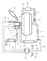
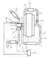
図3は過給機付内燃機関の一例を示すものであり、エンジン1の排気Gをタービン2の作動流体にしてコンプレッサ3を駆動するターボチャージャ4と、エアクリーナ5を通過してコンプレッサ3により圧縮された吸気Aをエンジン1へ送給する吸気経路6と、当該エンジン1の排気経路7のタービン2よりも上流側(排気マニホールド)から吸気経路6のコンプレッサ3よりも下流側へ至るEGR管路8と、主に燃料噴射制御を担うエンジン制御手段(ECU:Electronic Control Unit)9とを有している。
FIG. 3 shows an example of an internal combustion engine with a supercharger. The turbocharger 4 that drives the compressor 3 using the exhaust G of the engine 1 as the working fluid of the turbine 2 and the air cleaner 5 are compressed by the compressor 3.
吸気経路6には、コンプレッサ3が圧縮した吸気Aを冷却するためのインタクーラ10が組み込んであり、エアクリーナ5とコンプレッサ3の吸気導入口との間には、吸気Aの質量流量(kg/秒)や温度(℃)の情報11を得るためのエアフローメータ12が組み込んである。
The
排気経路7のタービン2の下流側には、マフラ13が設けてあり、EGR管路8には、排気Gを冷却するためのEGRクーラ14と排気Gの流量を調整するためのEGRバルブ15が直列に組み込んである。
A
タービン2のノズルベーンの開度は、信号16に基づき作動するアクチュエータ17により調整でき、例えば、一定の排気Gの流入量に対してノズルベーンの開度を拡げた場合は、排気Gの流速が下がってタービン2の回転数が低くなり、コンプレッサ3の吸気Aの吸い込み量が減るので、ターボチャージャ4の見掛け上の容量が増大する(同等の回転数を保つためにより多くの排気Gが必要になる)。
The opening degree of the nozzle vane of the turbine 2 can be adjusted by an
また逆に、一定の排気Gの流入量に対してノズルベーンの開度を狭めた場合は、排気Gの流速が上がってタービン2の回転数が高くなり、コンプレッサ3の吸気Aの吸い込み量が増すので、ターボチャージャ4の見掛け上の容量が減少する(より少ない排気Gで同等の回転数を保てる)。 On the other hand, when the opening degree of the nozzle vane is narrowed with respect to the fixed inflow amount of the exhaust gas G, the flow rate of the exhaust gas G increases, the rotational speed of the turbine 2 increases, and the intake amount of the intake air A of the compressor 3 increases. Therefore, the apparent capacity of the turbocharger 4 is reduced (the same rotational speed can be maintained with less exhaust G).
エンジン制御手段9は、予め設定してあるターボチャージャ4の質量流量制御マップとエアフローメータ12から得た情報11に基づく信号16をアクチュエータ17へ送ってタービン2のノズルベーンの開度を調整し、コンプレッサ3からエンジン1へ供給される吸気Aの質量流量が一定になるように調整する機能を具備している。
The engine control means 9 sends a
図3に示す過給機付内燃機関では、エンジン1が稼動状態であるとき、排気Gの大部分は、タービン2へ流入してコンプレッサ3を駆動した後、マフラ13を経て大気中に放出される。
In the supercharged internal combustion engine shown in FIG. 3, when the engine 1 is in an operating state, most of the exhaust G flows into the turbine 2 and drives the compressor 3, and then is released into the atmosphere via the
エアクリーナ5からコンプレッサ3に流入して圧縮された吸気Aは、インタクーラ10を通ってエンジン1へ送給され、これと同時に排気Gの一部がEGR管路8へ流入して、EGRクーラ14により冷却され且つEGRバルブ15で流量調整が行なわれた排気Gがエンジン1へ送給され、燃焼温度の低下が図られ、NOxの発生が低減することになる。
ターボチャージャ4のコンプレッサ3からエンジン1へ送給すべき吸気Aの質量流量が一定になるようにタービン2のノズルベーンの開度を調整する制御では、外気温度が高い場合に、ノズルベーンに開度を狭めてタービン2の回転数を上げ、空気密度の低下による吸気Aの質量流量の不足を補うことになるが、このような制御では、インタクーラ10やラジエータなどの冷却系の負荷が増えて最終的にはエンジンがオーバーヒートすることになる。
In the control for adjusting the opening degree of the nozzle vane of the turbine 2 so that the mass flow rate of the intake air A to be supplied from the compressor 3 of the turbocharger 4 to the engine 1 is constant, the opening degree is adjusted to the nozzle vane when the outside air temperature is high. Narrowing and increasing the rotation speed of the turbine 2 will compensate for the shortage of the mass flow rate of the intake air A due to a decrease in the air density. However, in such control, the load on the cooling system such as the
本発明は上述した実情に鑑みてなしたもので、エンジンのオーバーヒートを回避可能なターボチャージャ制御機構を提供することを目的としている。 The present invention has been made in view of the above-described circumstances, and an object thereof is to provide a turbocharger control mechanism capable of avoiding engine overheating.
上記目的を達成するために、請求項1に記載の発明は、タービンに可動ノズルベーンを装備したターボチャージャに付帯する回転数センサと、当該ターボチャージャのコンプレッサ上流側に設けたエアフローメータと、アクセル開度を検出するアクセルセンサと、エンジン冷却水温を計測する温度センサと、エンジン吸気系統に設けたブースト圧センサと、エンジンの燃料噴射制御を担い且つ各センサとエアフローメータから得た情報に基づいてコンプレッサの実吸気体積流量が体積流量制御マップに見合うように燃料噴射量を制御するエンジン制御手段とを備えている。 In order to achieve the above object, an invention according to claim 1 is directed to a rotational speed sensor attached to a turbocharger equipped with a movable nozzle vane in a turbine, an air flow meter provided upstream of a compressor of the turbocharger, and an accelerator opening. An accelerator sensor for detecting the engine temperature, a temperature sensor for measuring the engine cooling water temperature, a boost pressure sensor provided in the engine intake system, and a compressor based on information obtained from each sensor and the air flow meter for controlling fuel injection of the engine Engine control means for controlling the fuel injection amount so that the actual intake volume flow rate matches the volume flow rate control map.
請求項2に記載の発明は、エアフローメータから得た情報と質量流量制御マップに基づき可動ノズルベーンの開度を調整する機能、エアフローメータから得た情報から想定吸気体積流量を算出する機能、ブースト圧センサから得た情報と吸気体積流量に基づきターボチャージャの理想回転数を算出する機能、回転数センサで得たターボチャージャの実回転数が理想回転数を上回った場合に実回転数とブースト圧センサから得た情報と体積流量制御マップに基づき吸気体積流量が体積流量制御マップに見合うように燃料噴射量を制御する機能とを、エンジン制御手段に具備させている。 The invention according to claim 2 is a function for adjusting the opening degree of the movable nozzle vane based on the information obtained from the air flow meter and the mass flow rate control map, a function for calculating the assumed intake volume flow rate from the information obtained from the air flow meter, boost pressure A function to calculate the ideal speed of the turbocharger based on the information obtained from the sensor and the intake volume flow rate. When the actual speed of the turbocharger obtained by the speed sensor exceeds the ideal speed, the actual speed and boost pressure sensor. The engine control means is provided with a function of controlling the fuel injection amount so that the intake volume flow matches the volume flow control map based on the information obtained from the above and the volume flow control map.
本発明においては、各センサとエアフローメータから得た情報に基づき、エンジン制御手段がコンプレッサの吸気体積流量が体積流量制御マップに見合うように、燃料噴射量を減らしてターボチャージャの回転数を下げる。 In the present invention, based on the information obtained from each sensor and the air flow meter, the engine control means reduces the fuel injection amount and lowers the rotational speed of the turbocharger so that the intake volume flow rate of the compressor matches the volume flow rate control map.
本発明のターボチャージャ制御機構によれば、各センサとエアフローメータからの情報に基づいて、コンプレッサの実吸気体積流量が体積流量制御マップに見合うように、燃料噴射量を減らすので、外気温度が高い場合のエンジン冷却系の負荷を軽減することが可能になり、よって、エンジンのオーバーヒートを回避できる、という優れた効果を奏し得る。 According to the turbocharger control mechanism of the present invention, the fuel injection amount is reduced so that the actual intake volume flow rate of the compressor matches the volume flow rate control map based on information from each sensor and the air flow meter, so the outside air temperature is high. In this case, it is possible to reduce the load on the engine cooling system in this case, and thus it is possible to achieve an excellent effect of avoiding overheating of the engine.
以下、本発明の実施の形態を図面に基づき説明する。 Hereinafter, embodiments of the present invention will be described with reference to the drawings.
図1及び図2は本発明のターボチャージャ制御機構の実施の形態の一例を適用した過給機付内燃機関を示すものであり、図中、図3と同一の符号を付した部分は同一物を表している。 1 and 2 show a turbocharged internal combustion engine to which an example of an embodiment of a turbocharger control mechanism of the present invention is applied. In the figure, the same reference numerals as in FIG. Represents.
ターボチャージャ制御機構は、先述したエアフローメータ12と、アクセル開度を検出するアクセルセンサ18と、エンジン冷却水温を計測する温度センサ19と、吸気経路6に組み込んだブースト圧センサ20と、ターボチャージャ4に付帯する回転数センサ21と、エンジン1の燃料噴射制御を担い且つアクチュエータ17に信号16を送るエンジン制御手段22とを有している。
The turbocharger control mechanism includes the
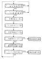
エンジン制御手段22には、質量流量制御マップとエアフローメータ12から得た情報11に基づく信号16をアクチュエータ17へ送ってタービン2のノズルベーンの開度を調整し、コンプレッサ3からエンジン1へ供給される吸気Aの質量流量が一定になるように調整する機能の他に、
a.アクセルセンサ18から得たアクセル開度の情報23に基づき、アクセル全開状態が予め設定してある時間を超えたか否かを判定する機能、
b.a項の要件が満たされた場合に、温度センサ19から得た水温の情報24に基づき、エンジン冷却水温が予め定めてある上限値を超えたか否かを判定する機能、
c.b項の要件が満たされた場合に、エアフローメータ12から得た吸気Aの質量流量や温度の情報11に基づき、吸気Aの体積流量Q1(立方m/分)を算出する機能、
d.ブースト圧センサ20から得た圧力の情報25に基づき、ターボ圧力比πC1を算出する機能、
e.体積流量Q1及びターボ圧力比πC1からターボチャージャ4の理想回転数NT0を算出する機能、
f.回転数センサ21で得た情報26、すなわち、ターボチャージャ4の実回転数NT1が理想回転数NT0以上になったか否を判定する機能と、
g.f項の要件が満たされた場合に、実回転数NT1とターボ圧力比πC1から目標体積流量Q0を算出し、設計条件により定まるターボチャージャ4固有の体積流量制御マップに目標体積流量Q0が見合うように燃料噴射量を減らしてターボチャージャ4の回転数を相対的に下げる機能、
h.燃料噴射量を減らした後、温度センサ19から得た情報24に基づき、エンジン冷却水温が上限値よりも若干低い値(例えば、上限値が95℃だとすると93℃程度)にまで下がったか否を判定する機能、
が設定してあり(図2参照)、エンジン1が稼働している間、a項の機能とb項の機能は判定を繰り返し実行するようになっている。
The engine control means 22 sends a
a. A function for determining whether or not the accelerator fully open state exceeds a preset time based on the
b. a function for determining whether or not the engine cooling water temperature has exceeded a predetermined upper limit value based on the
c. a function of calculating the volume flow rate Q1 (cubic m / min) of the intake air A based on the mass flow rate and
d. A function of calculating the turbo pressure ratio πC1 based on the
e. A function of calculating the ideal rotational speed NT0 of the turbocharger 4 from the volume flow rate Q1 and the turbo pressure ratio πC1;
f.
g. When the requirement of the term f is satisfied, the target volume flow Q0 is calculated from the actual rotational speed NT1 and the turbo pressure ratio πC1, and the target volume flow Q0 matches the volume flow control map unique to the turbocharger 4 determined by the design conditions. The function of reducing the fuel injection amount and lowering the rotational speed of the turbocharger 4 relatively,
h. After reducing the fuel injection amount, based on the
Is set (see FIG. 2), and while the engine 1 is operating, the function of the item a and the function of the item b are repeatedly determined.
つまり、g項の機能が発動すると、ターボチャージャ4の質量流量制御を体積流量制御に変えて燃料噴射量を減らすので、エンジン冷却系の負荷を軽減することが可能になり、エンジンのオーバーヒートを回避できる。 In other words, when the function of the g term is activated, the mass flow rate control of the turbocharger 4 is changed to the volume flow rate control to reduce the fuel injection amount, thereby reducing the load on the engine cooling system and avoiding the engine overheating. it can.
更に、f項の要件が満たされない場合はターボチャージャ4の質量流量制御を継続し、h項の要件が満たされた場合はターボチャージャ4の体積流量制御を質量流量制御に戻すことになる。 Further, when the requirement of the f term is not satisfied, the mass flow control of the turbocharger 4 is continued, and when the requirement of the h term is satisfied, the volume flow control of the turbocharger 4 is returned to the mass flow control.
なお、本発明のターボチャージャ制御機構は上述した実施の形態のみに限定されるものではなく、本発明の要旨を逸脱しない範囲において変更を加え得ることは勿論である。 It should be noted that the turbocharger control mechanism of the present invention is not limited to the above-described embodiment, and it goes without saying that modifications can be made without departing from the scope of the present invention.
本発明のターボチャージャ制御機構は、様々な車種に適用できる。 The turbocharger control mechanism of the present invention can be applied to various vehicle types.
1 エンジン
2 タービン
3 コンプレッサ
4 ターボチャージャ
6 吸気経路
12 エアフローメータ
18 アクセルセンサ
19 温度センサ
20 ブースト圧センサ
21 回転数センサ
22 エンジン制御手段
23〜26 情報
DESCRIPTION OF SYMBOLS 1 Engine 2 Turbine 3 Compressor 4
Claims (2)
Priority Applications (1)
| Application Number | Priority Date | Filing Date | Title |
|---|---|---|---|
| JP2004121228A JP2005299618A (en) | 2004-04-16 | 2004-04-16 | Turbocharger control mechanism |
Applications Claiming Priority (1)
| Application Number | Priority Date | Filing Date | Title |
|---|---|---|---|
| JP2004121228A JP2005299618A (en) | 2004-04-16 | 2004-04-16 | Turbocharger control mechanism |
Publications (1)
| Publication Number | Publication Date |
|---|---|
| JP2005299618A true JP2005299618A (en) | 2005-10-27 |
Family
ID=35331451
Family Applications (1)
| Application Number | Title | Priority Date | Filing Date |
|---|---|---|---|
| JP2004121228A Pending JP2005299618A (en) | 2004-04-16 | 2004-04-16 | Turbocharger control mechanism |
Country Status (1)
| Country | Link |
|---|---|
| JP (1) | JP2005299618A (en) |
Cited By (7)
| Publication number | Priority date | Publication date | Assignee | Title |
|---|---|---|---|---|
| WO2007145021A1 (en) * | 2006-06-12 | 2007-12-21 | Yanmar Co., Ltd. | Engine with supercharger |
| JP2008184922A (en) * | 2007-01-26 | 2008-08-14 | Hino Motors Ltd | Turbine protection device |
| WO2009066578A1 (en) * | 2007-11-20 | 2009-05-28 | Yanmar Co., Ltd. | Engine |
| WO2011099173A1 (en) | 2010-02-09 | 2011-08-18 | 三菱重工業株式会社 | Control device for engine with turbocharger |
| WO2015145924A1 (en) * | 2014-03-28 | 2015-10-01 | マツダ株式会社 | Control device for engine equipped with turbo-supercharger |
| CN110541753A (en) * | 2019-09-30 | 2019-12-06 | 中国民航大学 | A turbocharger turbine air intake cooling device |
| CN114151214A (en) * | 2021-11-03 | 2022-03-08 | 潍柴动力股份有限公司 | Engine air inlet signal correction method and device and engine |
-
2004
- 2004-04-16 JP JP2004121228A patent/JP2005299618A/en active Pending
Cited By (14)
| Publication number | Priority date | Publication date | Assignee | Title |
|---|---|---|---|---|
| US8191370B2 (en) | 2006-06-12 | 2012-06-05 | Yanmar Co., Ltd. | Engine with supercharger |
| RU2401388C2 (en) * | 2006-06-12 | 2010-10-10 | Янмар Ко., Лтд | Engine with supercharger (versions) |
| WO2007145021A1 (en) * | 2006-06-12 | 2007-12-21 | Yanmar Co., Ltd. | Engine with supercharger |
| JP2008184922A (en) * | 2007-01-26 | 2008-08-14 | Hino Motors Ltd | Turbine protection device |
| WO2009066578A1 (en) * | 2007-11-20 | 2009-05-28 | Yanmar Co., Ltd. | Engine |
| US8402953B2 (en) | 2007-11-20 | 2013-03-26 | Yanmar Co., Ltd. | Engine |
| WO2011099173A1 (en) | 2010-02-09 | 2011-08-18 | 三菱重工業株式会社 | Control device for engine with turbocharger |
| JP2011185263A (en) * | 2010-02-09 | 2011-09-22 | Mitsubishi Heavy Ind Ltd | Control device of engine with turbocharger |
| US10145297B2 (en) | 2014-03-28 | 2018-12-04 | Mazda Motor Corporation | Control device for engine equipped with turbo-supercharger |
| JP2015190414A (en) * | 2014-03-28 | 2015-11-02 | マツダ株式会社 | Control device for turbocharged engine |
| WO2015145924A1 (en) * | 2014-03-28 | 2015-10-01 | マツダ株式会社 | Control device for engine equipped with turbo-supercharger |
| CN110541753A (en) * | 2019-09-30 | 2019-12-06 | 中国民航大学 | A turbocharger turbine air intake cooling device |
| CN114151214A (en) * | 2021-11-03 | 2022-03-08 | 潍柴动力股份有限公司 | Engine air inlet signal correction method and device and engine |
| CN114151214B (en) * | 2021-11-03 | 2023-08-18 | 潍柴动力股份有限公司 | Engine air intake signal correction method and device and engine |
Similar Documents
| Publication | Publication Date | Title |
|---|---|---|
| JP4215069B2 (en) | Exhaust gas recirculation device for internal combustion engine | |
| CN102758687B (en) | Internal combustion engine control apparatus | |
| JP4534514B2 (en) | Diesel engine control device | |
| CN100470035C (en) | System for Controlling Turbocharger Compressor Surge | |
| US7261098B2 (en) | System and method for adjusting the exhaust gas recirculation rate in an internal combustion engine | |
| US8001953B2 (en) | Exhaust gas recirculation system for internal combustion engine and method for controlling the same | |
| CN101845986B (en) | Model-based control of airpath pressure limits by modulating turbo charger by-pass valve and variable-geometry turbine | |
| US20080295514A1 (en) | Exhaust Gas Recirculation Apparatus of an Internal Combustion Engine and Control Method Thereof | |
| CN101675223A (en) | Method of controlling a turbocharger | |
| JP2009523961A (en) | Diesel engine with supercharger | |
| JP2009528475A (en) | Method and apparatus for controlling the supercharged air of an internal combustion engine | |
| JP2004528503A (en) | Electronically controlled engine exhaust treatment system to reduce nitrogen oxide emissions | |
| JP4746389B2 (en) | Supercharging system | |
| JP2006336547A (en) | EGR device | |
| JP2009097362A (en) | Control device for engine with two-stage turbocharger | |
| US8571818B2 (en) | Method of dynamically estimating the fresh air flow rate supplied to an engine with high-pressure and low-pressure EGR circuits | |
| CN102317602A (en) | Supercharged diesel internal combustion engine, and method for controlling the airflow in such an engine | |
| JP2008546946A (en) | Supercharged diesel engine | |
| US7140360B2 (en) | System for controlling exhaust emissions produced by an internal combustion engine | |
| US20130192223A1 (en) | Exhaust system | |
| JP4492406B2 (en) | Diesel engine intake / exhaust system | |
| JP5491028B2 (en) | Method for an internal combustion engine with exhaust recirculation | |
| CN103195555B (en) | Control systems and methods for super turbo-charged engines | |
| JP2005299618A (en) | Turbocharger control mechanism | |
| JP2007263040A (en) | Engine three-stage turbocharging system |
Legal Events
| Date | Code | Title | Description |
|---|---|---|---|
| A621 | Written request for application examination |
Free format text: JAPANESE INTERMEDIATE CODE: A621 Effective date: 20070326 |
|
| A131 | Notification of reasons for refusal |
Free format text: JAPANESE INTERMEDIATE CODE: A131 Effective date: 20090915 |
|
| A02 | Decision of refusal |
Free format text: JAPANESE INTERMEDIATE CODE: A02 Effective date: 20100202 |