JP2005299564A - Exhaust manifold gasket - Google Patents
Exhaust manifold gasket Download PDFInfo
- Publication number
- JP2005299564A JP2005299564A JP2004119140A JP2004119140A JP2005299564A JP 2005299564 A JP2005299564 A JP 2005299564A JP 2004119140 A JP2004119140 A JP 2004119140A JP 2004119140 A JP2004119140 A JP 2004119140A JP 2005299564 A JP2005299564 A JP 2005299564A
- Authority
- JP
- Japan
- Prior art keywords
- exhaust manifold
- gasket
- cylinder head
- engine
- flange portion
- Prior art date
- Legal status (The legal status is an assumption and is not a legal conclusion. Google has not performed a legal analysis and makes no representation as to the accuracy of the status listed.)
- Pending
Links
Images

Landscapes
- Gasket Seals (AREA)
- Exhaust Silencers (AREA)
Abstract
【課題】シリンダヘッド及びヘッドカバー間から漏れ出て垂れたオイルが、その下方のエンジンの高温部分にかかるのを抑制することのできる排気マニホールドガスケットを提供する。
【解決手段】排気マニホールドガスケット28は、ガスケット本体及び樋部37を備える。ガスケット本体は、エンジン11におけるシリンダヘッド15と、そのシリンダヘッド15の外壁面15Aに取付けられる排気マニホールド25とにより挟持される。樋部37は、ガスケット本体の上端部に一体に形成され、かつシリンダヘッド15上のヘッドカバー24と排気マニホールド25とが互いに近接する空間S1について、エンジン11の気筒配列方向(紙面と直交する方向)の全域にわたって配置される。同気筒配列方向に直交する面での樋部37の断面形状は略V字状をなしている。
【選択図】 図1An exhaust manifold gasket is provided that can prevent oil that has leaked and dripped from between a cylinder head and a head cover from being applied to a hot portion of an engine below the cylinder head and a head cover.
An exhaust manifold gasket includes a gasket body and a flange portion. The gasket body is sandwiched between a cylinder head 15 in the engine 11 and an exhaust manifold 25 attached to an outer wall surface 15A of the cylinder head 15. The flange 37 is formed integrally with the upper end of the gasket body, and the cylinder arrangement direction of the engine 11 (direction perpendicular to the paper surface) in the space S1 in which the head cover 24 and the exhaust manifold 25 on the cylinder head 15 are close to each other. It is arranged over the whole area. The cross-sectional shape of the flange portion 37 on a plane orthogonal to the cylinder arrangement direction is substantially V-shaped.
[Selection] Figure 1
Description
本発明は、エンジンのシリンダヘッド及び排気マニホールド間から燃焼ガスが漏れ出るのを抑制する排気マニホールドガスケットに関するものである。 The present invention relates to an exhaust manifold gasket that suppresses leakage of combustion gas from between an engine cylinder head and an exhaust manifold.
一般的なエンジンにおいては、シリンダヘッドの外壁面に排気マニホールドがボルト等によって締結され、エンジンの運転に伴い各気筒で発生した燃焼ガスが、シリンダヘッドの対応する排気ポートから排気マニホールドに流出される。燃焼ガスは排気マニホールド内で1箇所に集められた後に下流の排気管へ流出される。この流通過程で燃焼ガスがシリンダヘッド及び排気マニホールド間から漏れ出るのを抑制するために、それらの間に排気マニホールドガスケットが配置される。 In a general engine, an exhaust manifold is fastened to an outer wall surface of a cylinder head with a bolt or the like, and combustion gas generated in each cylinder as the engine is operated flows out from a corresponding exhaust port of the cylinder head to the exhaust manifold. . The combustion gas is collected in one place in the exhaust manifold and then flows out to the downstream exhaust pipe. In order to prevent combustion gas from leaking between the cylinder head and the exhaust manifold during this flow process, an exhaust manifold gasket is disposed between them.
こうしたシリンダヘッド、排気マニホールドガスケット及び排気マニホールドに関連する技術として、例えば特許文献1に記載された「排気ガス再燃焼装置」がある。この装置では、排気マニホールドの上方に気筒配列方向に延びる二次空気分配管が設けられている。また、二次空気分配管の底壁に下方へ延びる空気噴射管が設けられ、その空気噴射管の下半部が排気マニホールドの内部に入り込んでいる。さらに、空気噴射管は、排気マニホールド内では、その上壁の近傍において排気ポートの軸線方向に向うように折曲げられている。
As a technique related to such a cylinder head, an exhaust manifold gasket, and an exhaust manifold, for example, there is an “exhaust gas recombustion device” described in
上記排気ガス再燃焼装置によると、空気噴射管から噴出された二次空気が排気ポートの上壁に沿って流れる。この二次空気により、排気ポートの排気バルブ近傍の排気ガス(燃焼ガス)が排気ポートの下壁に沿って強制的に押出され、排気ポート内が二次空気で満たされる。そのため、次回の排気行程で、排気バルブが開き、燃焼室から排出される高温高圧の排気ガスが、排気ポート内の上記二次空気によって再燃焼される。この再燃焼によって、エンジンの運転開始時に排気ガスの温度が上昇するため、触媒コンバータの早期活性化を図ることができる。 According to the exhaust gas recombustion device, the secondary air ejected from the air injection pipe flows along the upper wall of the exhaust port. By this secondary air, the exhaust gas (combustion gas) in the vicinity of the exhaust valve of the exhaust port is forcibly pushed out along the lower wall of the exhaust port, and the interior of the exhaust port is filled with the secondary air. Therefore, in the next exhaust stroke, the exhaust valve is opened, and the high-temperature and high-pressure exhaust gas discharged from the combustion chamber is reburned by the secondary air in the exhaust port. Due to this recombustion, the temperature of the exhaust gas rises at the start of engine operation, so that the catalytic converter can be activated early.
なお、本発明にかかる先行技術文献としては、上述した特許文献1のほかに下記の特許文献2が挙げられる。
ところが、上記特許文献1を含め一般的なエンジンでは、シリンダヘッドに対するヘッドカバーの取付け部が二次空気分配管や排気マニホールドの上方に位置している場合、次の不具合が起るおそれがある。それは、シリンダヘッド内で動弁機構等を潤滑等するために用いられているオイルが、シリンダヘッド及びヘッドカバー間から漏れ出て垂れると、温度の高くなった二次空気分配管や排気マニホールドにかかることである。こうした不具合は、各気筒が傾斜して配列されて、上記取付け部が排気マニホールドの上方に位置する傾向にあるV型エンジンで特に起りやすい。
However, in general engines including the above-mentioned
本発明はこのような実情に鑑みてなされたものであって、その目的は、シリンダヘッド及びヘッドカバー間から漏れ出て垂れたオイルが、その下方のエンジンの高温部分にかかるのを抑制することのできる排気マニホールドガスケットを提供することにある。 The present invention has been made in view of such a situation, and an object of the present invention is to suppress oil leaking and dripping from between the cylinder head and the head cover from being applied to a high temperature portion of the engine below. It is to provide an exhaust manifold gasket that can be used.
以下、上記目的を達成するための手段及びその作用効果について記載する。
請求項1に記載の発明では、エンジンにおけるシリンダヘッドと、そのシリンダヘッドの外壁面に取付けられる排気マニホールドとにより挟持されるガスケット本体と、前記ガスケット本体に接続され、かつ前記シリンダヘッド上のヘッドカバーと前記排気マニホールドとが互いに近接する空間に配置される樋部とを備えている。
In the following, means for achieving the above object and its effects are described.
In the first aspect of the present invention, a gasket main body sandwiched between a cylinder head in the engine and an exhaust manifold attached to an outer wall surface of the cylinder head; a head cover connected to the gasket main body and on the cylinder head; The exhaust manifold is provided with a flange portion disposed in a space close to each other.
上記の構成によれば、シリンダヘッド内のオイルが、ヘッドカバーの同シリンダヘッドに対する取付け部(ヘッドカバー及びシリンダヘッド間)から漏れ出て、ヘッドカバーと排気マニホールドとが互いに近接する空間に垂れた場合、そのオイルは同空間に配置された樋部上に落下して受止められる。この樋部は排気マニホールドよりも上方に位置している。このため、オイルが樋部よりも下方へ落下して排気マニホールド等、取付け部下方の高温部分にかかる現象が起きにくくなる。 According to the above configuration, when the oil in the cylinder head leaks from the attachment portion (between the head cover and the cylinder head) of the head cover to the cylinder head, and the head cover and the exhaust manifold hang down in a space close to each other, The oil falls and is received on the collar part arranged in the same space. This flange is located above the exhaust manifold. For this reason, the phenomenon that the oil falls below the flange and the high temperature portion below the mounting portion such as the exhaust manifold is less likely to occur.
請求項2に記載の発明では、請求項1に記載の発明において、前記エンジンの気筒配列方向に直交する面での前記樋部の断面形状が略V字状をなしているとする。
上記の構成によれば、ヘッドカバー及びシリンダヘッド間からオイルが漏れ出て垂れた場合、そのオイルは樋部上に落下する。このオイルは、V字状断面を有する樋部の底部に集められる。このため、一旦樋部上に落下したオイルが、その樋部から溢れる等して落下する現象が起りにくい。
According to a second aspect of the present invention, in the first aspect of the present invention, it is assumed that the cross-sectional shape of the flange portion in a plane perpendicular to the cylinder arrangement direction of the engine is substantially V-shaped.
According to said structure, when oil leaks out from between a head cover and a cylinder head and it drips, the oil will fall on a collar part. This oil is collected at the bottom of the collar with a V-shaped cross section. For this reason, the phenomenon that the oil once dropped on the buttock overflows from the buttock, for example, does not easily occur.
請求項3に記載の発明では、請求項1又は2に記載の発明において、前記樋部は前記ガスケット本体に一体に形成されているとする。
上記の構成によれば、樋部をガスケット本体とは別部材によって構成した場合に比べて部品点数が少なくてすみ、また、樋部をガスケット本体に別途固定する構造が不要となる。
According to a third aspect of the present invention, in the first or second aspect of the present invention, the flange portion is formed integrally with the gasket body.
According to the above configuration, the number of parts can be reduced as compared with the case where the flange portion is formed of a member different from the gasket body, and a structure for separately fixing the flange portion to the gasket body is not necessary.
請求項4に記載の発明では、請求項1〜3のいずれか1つに記載の発明において、前記樋部は、前記ヘッドカバーと前記排気マニホールドとが互いに近接する空間について、前記エンジンの気筒配列方向の全域にわたって配置されているとする。 According to a fourth aspect of the present invention, in the invention according to any one of the first to third aspects, the flange portion has a cylinder arrangement direction of the engine in a space where the head cover and the exhaust manifold are close to each other. It is assumed that it is arranged over the entire area.
上記の構成によれば、ヘッドカバー及びシリンダヘッド間から漏れ出て垂れたオイルは、その漏れ出た箇所に拘らず、ヘッドカバーと排気マニホールドとが近接する空間について気筒配列方向の全域にわたって配置された樋部によって確実に受止められる。 According to the above configuration, the oil leaking and dripping from between the head cover and the cylinder head is disposed over the entire area in the cylinder arrangement direction in the space where the head cover and the exhaust manifold are close to each other regardless of the leaked portion. It is reliably received by the part.
請求項5に記載の発明では、請求項4に記載の発明において、前記ガスケット本体が前記シリンダヘッド及び前記排気マニホールドにより挟持された状態では、前記樋部は、前記エンジンの気筒配列方向に傾斜するものであるとする。 According to a fifth aspect of the present invention, in the fourth aspect of the present invention, in the state where the gasket body is sandwiched between the cylinder head and the exhaust manifold, the flange portion is inclined in the cylinder arrangement direction of the engine. Suppose it is a thing.
上記の構成によれば、ヘッドカバー及びシリンダヘッド間から垂れたオイルは樋部上に落下すると、その樋部がエンジンの気筒配列方向に傾斜していることから、その傾斜の低所へ向けて流下する。そして、オイルは樋部の最も低くなった箇所(樋部の端)に至ると、そこから落下する。前述したように樋部が気筒配列方向の全域にわたって配置されていることから、落下したオイルは排気マニホールドから気筒配列方向に離れた箇所を通ることとなり、排気マニホールドにかかるおそれはない。 According to the above configuration, when the oil dripping from between the head cover and the cylinder head falls on the flange, the flange is inclined toward the cylinder arrangement direction of the engine, and therefore flows down toward the lower portion of the inclination. To do. When the oil reaches the lowest point of the buttock (end of the buttock), it falls from there. As described above, since the flange portion is disposed over the entire area in the cylinder arrangement direction, the dropped oil passes through a portion away from the exhaust manifold in the cylinder arrangement direction, and there is no possibility of being applied to the exhaust manifold.
請求項6に記載の発明では、請求項1〜5のいずれか1つに記載の発明において、前記樋部には突部及び凹部の少なくとも一方が設けられているとする。
上記の構成によれば、樋部に突部及び凹部の少なくとも一方が設けられることにより、これらの突部や凹部がなく平らな場合に比べて樋部の剛性が高くなる。これに伴い樋部の共振周波数が高くなって、振動しにくくなり騒音の発生が抑制される。
In the invention described in claim 6, in the invention described in any one of claims 1-5, it is assumed that at least one of a protrusion and a recess is provided in the flange portion.
According to said structure, by providing at least one of a protrusion and a recessed part in a collar part, the rigidity of a collar part becomes high compared with the case where these protrusions and a recessed part do not exist and are flat. Along with this, the resonance frequency of the heel portion becomes high, and it becomes difficult to vibrate and the generation of noise is suppressed.
請求項7に記載の発明では、請求項6に記載の発明において、前記突部及び凹部の少なくとも一方は前記樋部を塑性加工することにより形成されたものであるとする。
上記の構成によれば、樋部の一部に対し塑性加工をすることにより突部及び凹部の少なくとも一方が形成される。そのため、突部や凹部の形成のために、別部材を用意して樋部に固定しなくてもよい。従って、新たな部材を追加することなく上記騒音や振動を抑制する効果を得ることができる。
In the invention described in claim 7, in the invention described in claim 6, it is assumed that at least one of the projecting portion and the recessed portion is formed by plastic working the flange portion.
According to said structure, at least one of a protrusion and a recessed part is formed by carrying out plastic working with respect to a part of collar part. Therefore, it is not necessary to prepare a separate member and fix it to the collar for the formation of the protrusion and the recess. Therefore, the effect of suppressing the noise and vibration can be obtained without adding a new member.
以下、本発明の排気マニホールドガスケットを具体化した一実施形態について、図面を参照して説明する。本実施形態では、自動車用エンジン、特に、一対のバンクがV字状をなすように配置されたV型エンジンに適用される排気マニホールドガスケットを想定している。 Hereinafter, an embodiment of an exhaust manifold gasket according to the present invention will be described with reference to the drawings. In the present embodiment, an exhaust manifold gasket is assumed which is applied to an automobile engine, in particular, a V-type engine in which a pair of banks are arranged in a V shape.
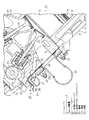
図1は、エンジン11におけるシリンダブロック12の一方(左側)のバンク、及びその近傍の内部構造を示している。シリンダブロック12の各バンクは、紙面に直交する方向に配列された複数の気筒(シリンダ)13を有しており、各気筒13内にピストン14が往復動可能に収容されている。
FIG. 1 shows one (left side) bank of the
シリンダブロック12の各バンク上にはシリンダヘッド15が締結されている。各気筒13内において、ピストン14の頂面と、シリンダヘッド15とにより囲まれた空間によって燃焼室16が形成されている。バンク毎のシリンダヘッド15には、気筒13毎に吸気ポート17及び排気ポート18がそれぞれ設けられている。各吸気ポート17の一端(図1の右端)はシリンダヘッド15の内壁面において開口し、他端(図1の左端)は燃焼室16に面して開口している。同様に、各排気ポート18の一端(図1の左端)はシリンダヘッド15の外壁面15Aにおいて開口し、他端(図1の右端)は燃焼室16に面して開口している。これらの吸・排気ポート17,18を開閉するために、シリンダヘッド15には吸気バルブ19及び排気バルブ20がそれぞれ往復動可能に支持されている。
A
また、シリンダヘッド15において、吸・排気バルブ19,20の各上端部の近傍には、それぞれカム21Aを有するカムシャフト(排気側のみ図示)21が回転可能に設けられている。各カムシャフト21の回転により吸・排気バルブ19,20が往復動し、吸・排気ポート17,18が開放又は閉鎖される。
In the
なお、シリンダヘッド15上には、ゴム等の弾性材料からなるヘッドカバーガスケット23を介してヘッドカバー24が載置され、同ヘッドカバー24がボルト(図示略)によりシリンダヘッド15に締結されている。このヘッドカバー24によって、シリンダヘッド15上部の動弁機構等が覆われている。
A
吸気ポート17には吸気通路(図示略)が接続されており、エンジン11の外部の空気が吸気通路及び吸気ポート17を通過して燃焼室16に取り込まれる。この空気は、燃料噴射弁から噴射された燃料と混ざり合って混合気となる。さらに、この混合気は点火プラグの電気火花によって着火され、爆発・燃焼する。このときに生じた高温高圧の燃焼ガスによりピストン14が往復動され、エンジン11の出力軸であるクランクシャフトが回転されて、エンジン11の駆動力(出力トルク)が得られる。
An intake passage (not shown) is connected to the
排気ポート18には排気通路が接続されており、燃焼室16で生じた燃焼ガスが排気通路を通ってエンジン11の外部へ排出される。排気通路の一部は、シリンダヘッド15の外壁面15Aにボルト22により締結された排気マニホールド25によって構成されている。
An exhaust passage is connected to the
また、シリンダヘッド15の内部には、気筒13毎の排気ポート18に二次空気を導入するための二次空気導入通路26が設けられている。二次空気導入通路26の一端(図1の右端)は排気ポート18に接続され、他端(図1の左端)はシリンダヘッド15の外壁面15Aに開口している。ヘッドカバー24と排気マニホールド25とが互いに近接する空間には、エンジン11の気筒配列方向に延びる二次空気分配管27が配置されている。この二次空気分配管27は排気マニホールド25のフランジ25Aに溶接等の手段によって固定されている。二次空気分配管27には、例えば電動エアポンプ(図示略)から吐出された二次空気が供給される。二次空気分配管27の内部空間は二次空気の供給通路となっており、この二次空気の供給通路が前述した排気ポート18毎の二次空気導入通路26に連通している。そのため、二次空気は二次空気分配管27内で分配され、二次空気導入通路26を通って対応する排気ポート18に導かれる。
Further, a secondary
例えば、内燃機関が冷間始動等され、排気通路途中に配設された触媒が未だ活性化していない期間には、上記のように二次空気が排気ポート18に導入されることにより、排気中の炭化水素(HC)や一酸化炭素(CO)が酸化されて、それらHCやCOの残存量が減少する。触媒が活性化していない期間におけるHCやCOの外部への放出が抑制され、排気エミッションが改善される。また、このような未燃焼ガスの燃焼(酸化)により触媒が速やかに昇温され、エンジン11の冷間始動後であっても、同触媒が早期に活性状態となる。
For example, during a period when the internal combustion engine is cold started and the catalyst disposed in the exhaust passage is not yet activated, the secondary air is introduced into the
ところで、燃焼ガスが排気ポート18から排気マニホールド25へ流れる過程で、シリンダヘッド15に対する排気マニホールド25の締結箇所から漏れ出るのを抑制するために、シリンダヘッド15及び排気マニホールド25間には排気マニホールドガスケット28が介在されている。表現を変えると、この排気マニホールドガスケット28はシリンダヘッド15の外壁面15A及び排気マニホールド25によって挟持されている。
Incidentally, an exhaust manifold gasket is provided between the
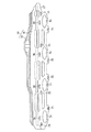
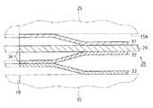
排気マニホールドガスケット28は、図5に示すように耐熱性を有する材料、例えばステンレス鋼等の金属材料によってそれぞれ形成された複数枚(本実施形態では4枚)の板材を重ね合せることによって形成されている。このうちの1枚は、排気マニホールドガスケット28の主要部をなすガスケット本体29となっており、気筒配列方向(図5の左右方向)に細長い形状をなしている。他の3枚の板材31〜33は、前記ガスケット本体29よりも薄く形成されている。これら3枚の板材31〜33のうちの1枚(31)はガスケット本体29の排気マニホールド25側の面に重ね合され、2枚(32,33)はシリンダヘッド15側の面に順に重ね合されている。板材31〜33はかしめによりガスケット本体29に係止されている。
As shown in FIG. 5, the
ガスケット本体29及び3枚の板材31〜33において、排気ポート18に対応する箇所には排気孔34があけられている。ガスケット本体29の両面に重ねられる2枚の板材31,32において、排気孔34の周囲の箇所は、そのガスケット本体29からそれぞれ離間するように曲げ形成されている。さらに、シリンダヘッド15に最も近い板材33は、排気孔34の周囲の箇所において、板材32の上記離間部分に重ね合されている。同板材33における前記重ね合せ部分の周囲は、前記板材32から離間するように曲げ形成されている。これら曲げ形成された箇所は、他の箇所よりも弾性変形しやすくなっている。
In the gasket
なお、上記のように曲げ形成するのは、排気マニホールドガスケット28がシリンダヘッド15及び排気マニホールド25によって挟持されたときに、排気孔34の周囲のシールの必要な箇所におけるシリンダヘッド15及び排気マニホールド25に対するシール面圧を高めて、シールを確実なものとするためである。
The bending is formed as described above when the
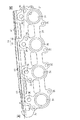
図2及び図3に示すように、ガスケット本体29及び3枚の板材31〜33において、各排気孔34の周囲には、前記ボルト22が挿通又は螺入されるねじ孔35と、二次空気分配管27で分配された二次空気が通過する二次空気孔36とがそれぞれあけられている。そして、排気マニホールド25に挿通されたボルト22が、対応するねじ孔35を通じてシリンダヘッド15に螺入されることで、排気マニホールド25及び排気マニホールドガスケット28がともにシリンダヘッド15に締結されている。
As shown in FIGS. 2 and 3, in the gasket
ここで、エンジン11においては、図1に示すようにシリンダヘッド15内で動弁機構等を潤滑等するために用いられているオイルが、シリンダヘッド15とヘッドカバー24との隙間、より正確にはヘッドカバーガスケット23とシリンダヘッド15との間、又は同ガスケット23とヘッドカバー24との間から漏れ出て垂れる場合がある。この垂れたオイルは、その下方に位置する温度の高くなった二次空気分配管27や排気マニホールド25にかかるおそれがある。
Here, in the
そこで、本実施形態では、ガスケット本体29に、その上端からヘッドカバー24と二次空気分配管27とが互いに接近している空間S1へ延びる樋部37が一体に形成されている。同空間S1は、ヘッドカバー24と排気マニホールド25とが互いに接近する空間の一部をなしている。
Therefore, in the present embodiment, the
エンジン11の気筒配列方向についての樋部37の長さ(図2及び図3における左右長)は、排気マニホールド25の同方向の長さと同じかそれよりもわずかに長く設定されている。そして、樋部37は、ヘッドカバー24と二次空気分配管27(排気マニホールド25)とが互いに近接する上記空間S1について、気筒配列方向の全域にわたって配置されている。
The length of the
樋部37は、大別すると第1オイル受け部38と第2オイル受け部39とからなる。第1オイル受け部38は樋部37の大部分を占めるものであり、略平板状をなし、ガスケット本体29に対し略直交している(図1参照)。第2オイル受け部39は第1オイル受け部38の端部を略上方へ折曲げることにより形成されている。そのため、排気マニホールドガスケット28がシリンダヘッド15及び排気マニホールド25間に配置された使用状態では、第1オイル受け部38はガスケット本体29から離れるほど低くなるよう傾斜し、第2オイル受け部39はそれとは逆に、ガスケット本体29から離れるほど高くなるよう傾斜する。このように、エンジン11の気筒配列方向に直交する面での樋部37の断面形状が略V字状をなしている。
The
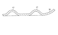
図3、図4及び図6に示すように、樋部37の一部、ここでは第1オイル受け部38には、上方へ突出する突部として多数の突起41が形成されている。これらの突起41は、第1オイル受け部38を塑性加工することによりされたものである。
As shown in FIGS. 3, 4, and 6, a plurality of
上記構成の排気マニホールドガスケット28がシリンダヘッド15及び排気マニホールド25によって挟持される(V型)エンジン11は、通常、クランクシャフトが前端ほど高くなるように傾斜した状態で車両に搭載される。この搭載に伴い、図3に示すように、バンク毎の排気マニホールドガスケット28もまた前側ほど高くなるよう、水平面に対し所定の角度αをもって傾斜する。
The
上記エンジン11の運転時には、排気マニホールド25の温度が高くなり、その排気マニホールド25から放出される熱の影響を受けた二次空気分配管27の温度も高くなる。こうした状況のもと、シリンダヘッド15内で動弁機構等を潤滑等するために用いられているオイルが、シリンダヘッド15とヘッドカバー24との隙間であってヘッドカバーガスケット23によるシール部分から漏れ出て垂れた場合、そのオイルは、空間S1に配置された樋部37上に落下する。この樋部37が略V字状の断面を有していることから、前記のようにしてオイル受け部38,39上に落下したオイルは樋部37の底部に集められる。オイルが樋部37から溢れる等して下方へ落下し、二次空気分配管27、排気マニホールド25等の高温部分にかかる現象は起きにくい。
During operation of the
樋部37上に落下したオイルは、前述したように樋部37がエンジン11の気筒配列方向に角度αで傾斜していることから、その傾斜の低所へ向けて流下する。ここで、樋部37は、空間S1について、エンジン11の気筒配列方向の全域にわたって配置されている。このことから、オイルは樋部37上を流下し、排気マニホールド25から気筒配列方向に離れた箇所に位置する樋部37の端部(最下端部)に至ると、そこから落下する。そのため、オイルが排気マニホールド25にかかるおそれはない。
As described above, the oil that has fallen on the
ところで、樋部37の多くの部分を占める第1オイル受け部38が略平板状をなしていることから、剛性が不足して振動しやすく騒音を発生させる原因となり得る。この樋部37を振動させる原因の1つに、排気が排気マニホールド25内を流れる際に発する流動音が挙げられる。この流動音が樋部37に伝達されて放射される。
By the way, since the 1st
この点、本実施形態では、第1オイル受け部38に多数の突起41が形成されている。これらの突起41は第1オイル受け部38の剛性を高めて共振周波数を高くする。そのため、第1オイル受け部38が振動しにくく騒音が発生しにくい。
In this regard, in the present embodiment, a large number of
そのほかにも樋部37は遮熱板としても機能する。すなわち、高温となった二次空気分配管27や排気マニホールド25からは輻射熱が放出される。ここで、仮に空間S1に何ら輻射熱を遮るものがないとすると、その輻射熱は、シリンダヘッド15、ヘッドカバー24、ヘッドカバーガスケット23等に伝達される。これらのうち、特にヘッドカバーガスケット23はゴム等、耐熱性がさほど高くない材料によって形成されている。そのため、ヘッドカバーガスケット23が熱によって変形したり劣化したりするおそれがある。
In addition, the
この点、本実施形態では空間S1に樋部37が配置されている。この樋部37によって上記輻射熱が遮られ、シリンダヘッド15、ヘッドカバー24、ヘッドカバーガスケット23等に伝達されにくくなる。このため、輻射熱の伝達に起因する上記不具合が解消又は抑制される。
In this regard, in the present embodiment, the
以上詳述した本実施形態によれば、次の効果が得られる。
(1)シリンダヘッド15及び排気マニホールド25により挟持されるガスケット本体29と、ヘッドカバー24及び二次空気分配管27が互いに近接する空間S1に位置する樋部37とにより排気マニホールドガスケット28を構成している。そのため、シリンダヘッド15及びヘッドカバー24間から漏れ出て垂れたオイルを樋部37によって受止めることで、その下方の高温の二次空気分配管27にかかるのを抑制することができる。
According to the embodiment described in detail above, the following effects can be obtained.
(1) An
樋部37が配置される空間S1は、ヘッドカバー24及び排気マニホールド25が互いに近接する空間の一部でもある。そのため、シリンダヘッド15及びヘッドカバー24間から漏れ出て垂れたオイルが、その下方の高温の排気マニホールド25にかかるのを樋部37によって抑制することもできる。
The space S1 in which the
これらの効果は、各気筒が傾斜して配列されて、ヘッドカバー24のシリンダヘッド15に対する取付け部が、排気マニホールド25の上方に位置する本実施形態のようなV型のエンジン11において特に有効である。
These effects are particularly effective in the V-
(2)樋部37を第1及び第2オイル受け部38,39によって構成し、エンジン11の気筒配列方向に直交する面での樋部37の断面形状を略V字状にしている。そのため、ヘッドカバー24及びシリンダヘッド15間から漏れ出て垂れたオイルを樋部37の底部に集めることができる。一旦樋部37上に落下したオイルが、その樋部37から溢れる等して落下する現象を抑制することができる。
(2) The
(3)樋部37をガスケット本体29に一体に形成している。このため、樋部37をガスケット本体29とは別部材によって構成した場合に比べて部品点数が少なくてすみ、また、樋部37をガスケット本体29に固定する構造が不要となる。
(3) The
(4)樋部37をガスケット本体29の一部としている。このため、ガスケット本体29をシリンダヘッド15の外壁面15Aと排気マニホールド25との間に装着することで、樋部37を空間S1の所望箇所に確実に配置することができる。
(4) The
(5)樋部37を、ヘッドカバー24と排気マニホールド25とが互いに近接する空間について、エンジン11の気筒配列方向の全域にわたって配置している。このため、シリンダヘッド15及びヘッドカバー24間について、気筒配列方向のどの箇所から垂れたオイルであっても樋部37によって確実に受止め、排気マニホールド25にかかりにくくすることができる。
(5) The
(6)V型エンジン11は、通常、そのクランクシャフトが前側ほど高くなるように傾斜した状態で車両に搭載される。これに伴い、シリンダヘッド15及び排気マニホールド25間に配置された排気マニホールドガスケット28もまた同方向、すなわち気筒配列方向に傾斜する。
(6) The V-
そのため、ヘッドカバー24及びシリンダヘッド15間から垂れて樋部37上に落下したオイルを、気筒配列方向に傾斜した樋部37に沿って低所へ向けて流下させ、排気マニホールド25から気筒配列方向に離れた箇所から落下させることができる。従って、樋部37から落下したオイルが排気マニホールド25にかかるのを確実に抑制することができる。
Therefore, the oil that hangs down from between the
(7)ヘッドカバー24と二次空気分配管27(排気マニホールド25)とが互いに近接する空間S1に樋部37を配置することで、二次空気分配管27や排気マニホールド25から放出される輻射熱を樋部37によって遮ることができる。その結果、ヘッドカバーガスケット23等が過剰に昇温して変形したり劣化したりするのを抑制することができる。
(7) By disposing the
(8)ガスケット本体29に樋部37を追加することにより、振動、騒音等の発生対象箇所が増える。これは、樋部37がなければ本来起らない不具合である。
この点、本実施形態では、樋部37の第1オイル受け部38に多数の突起41を形成することで樋部37の剛性を高めている。このため、樋部37による効果(オイルの高温部分の落下抑制、遮熱)を確保しつつ、樋部37が振動して騒音を発生する不具合を解消することができる。
(8) By adding the
In this regard, in this embodiment, the rigidity of the
(9)第1オイル受け部38を塑性加工することにより突起41を形成している。そのため、突起41の形成のために別部材を用意して樋部37に固定しなくてもよい。従って、新たな部材を追加することなく上記騒音や振動を抑制する効果を得ることができる。
(9) The
なお、本発明は次に示す別の実施形態に具体化することができる。
・上記実施形態における突起41を、第1オイル受け部38の下方へ突出するように塑性加工してもよい。ただし、樋部37上に落下したオイルがたまりにくいという点で突起41を上方へ突出させる方が望ましい。
Note that the present invention can be embodied in another embodiment described below.
-You may carry out the plastic processing so that the
・突部として、突起41に代えて樋部37にリブを形成してもよく、この場合にも樋部37の剛性を高めることができる。この場合、リブを格子状に形成すると樋部37の剛性を効率よく高めることができる。
As a protrusion, a rib may be formed on the
・第1オイル受け部38の剛性を高めるという観点からは、突部(突起41)に代えて凹部を設けてもよい。また、突部及び凹部の両方を第1オイル受け部38に設けてもよい。
-From a viewpoint of improving the rigidity of the 1st
・第2オイル受け部39にも突部及び凹部の少なくとも一方を設けてもよい。
・突起41を樋部37とは別の部材によって構成してもよく、この場合にも前記実施形態と同様の効果が得られる。ただし、突起41を樋部37に固定する構造が別途必要になる。
The second
The
・樋部37をガスケット本体29とは別部材によって構成してもよい。この場合、樋部37をガスケット本体29に固定する構造が別途必要になる。
・本発明は、前記実施形態とは異なる箇所(空間S1とは異なる箇所)に二次空気分配管27が設けられたり、同二次空気分配管27が設けられないタイプのエンジンのための排気マニホールドガスケットにも適用可能である。ただし、いずれの場合でも、樋部37は、ヘッドカバー24と排気マニホールド25とが互いに近接する空間に配置される。
-You may comprise the
-The present invention is an exhaust for an engine of a type in which the secondary
・本発明はV型エンジンに限らず、直列型エンジン用排気マニホールドガスケットにも適用可能である。 The present invention is not limited to a V-type engine but can be applied to an exhaust manifold gasket for an in-line engine.
11…エンジン、15…シリンダヘッド、15A…外壁面、24…ヘッドカバー、25…排気マニホールド、28…排気マニホールドガスケット、29…ガスケット本体、37…樋部、41…突起(突部)、S1…空間。
DESCRIPTION OF
Claims (7)
前記ガスケット本体に接続され、かつ前記シリンダヘッド上のヘッドカバーと前記排気マニホールドとが互いに近接する空間に配置される樋部と
を備えることを特徴とする排気マニホールドガスケット。 A gasket body sandwiched between a cylinder head in the engine and an exhaust manifold attached to an outer wall surface of the cylinder head;
An exhaust manifold gasket comprising: a flange that is connected to the gasket body and is disposed in a space in which a head cover on the cylinder head and the exhaust manifold are close to each other.
Priority Applications (1)
| Application Number | Priority Date | Filing Date | Title |
|---|---|---|---|
| JP2004119140A JP2005299564A (en) | 2004-04-14 | 2004-04-14 | Exhaust manifold gasket |
Applications Claiming Priority (1)
| Application Number | Priority Date | Filing Date | Title |
|---|---|---|---|
| JP2004119140A JP2005299564A (en) | 2004-04-14 | 2004-04-14 | Exhaust manifold gasket |
Publications (1)
| Publication Number | Publication Date |
|---|---|
| JP2005299564A true JP2005299564A (en) | 2005-10-27 |
Family
ID=35331408
Family Applications (1)
| Application Number | Title | Priority Date | Filing Date |
|---|---|---|---|
| JP2004119140A Pending JP2005299564A (en) | 2004-04-14 | 2004-04-14 | Exhaust manifold gasket |
Country Status (1)
| Country | Link |
|---|---|
| JP (1) | JP2005299564A (en) |
-
2004
- 2004-04-14 JP JP2004119140A patent/JP2005299564A/en active Pending
Similar Documents
| Publication | Publication Date | Title |
|---|---|---|
| AU2010274133B2 (en) | Muffler attachment system | |
| US8844276B2 (en) | Exhaust muffler for general-purpose engine | |
| US8813716B2 (en) | Pre-combustion chamber tip | |
| US20100251993A1 (en) | Bi-fuel internal combustion engine | |
| JP2006037862A (en) | Secondary air supply structure for internal combustion engine | |
| JP5432856B2 (en) | Oil separator arrangement structure | |
| JP4455423B2 (en) | General-purpose engine muffler structure | |
| JP2005299564A (en) | Exhaust manifold gasket | |
| JP4970383B2 (en) | General-purpose engine exhaust muffler | |
| JP2019203474A (en) | Air intake device of internal combustion engine | |
| JP4334007B2 (en) | Internal combustion engine provided with oil filter device | |
| JP4359265B2 (en) | General-purpose engine muffler cover structure | |
| JP2011214446A (en) | Internal combustion engine | |
| JP7740130B2 (en) | internal combustion engine | |
| JP2020169576A (en) | Exhaust structure of internal combustion engine | |
| JP7016596B2 (en) | Support bracket | |
| JP2025136473A (en) | internal combustion engine | |
| KR200162566Y1 (en) | Leakage prevention device of cylinder head | |
| JP2025008834A (en) | Exhaust system for internal combustion engines | |
| JP5704091B2 (en) | Variable compression ratio internal combustion engine | |
| JP2007303341A (en) | Resin intake manifold for internal combustion engine and internal combustion engine | |
| JP2017066973A (en) | Exhaust connection part structure of engine | |
| JP2014020303A (en) | Piston and piston ring for internal combustion engine | |
| JP2001200933A (en) | Cylinder head gasket | |
| JP2007170278A (en) | Lubrication structure of internal combustion engine |
Legal Events
| Date | Code | Title | Description |
|---|---|---|---|
| A621 | Written request for application examination |
Free format text: JAPANESE INTERMEDIATE CODE: A621 Effective date: 20070321 |
|
| A977 | Report on retrieval |
Effective date: 20090401 Free format text: JAPANESE INTERMEDIATE CODE: A971007 |
|
| A131 | Notification of reasons for refusal |
Effective date: 20090616 Free format text: JAPANESE INTERMEDIATE CODE: A131 |
|
| A521 | Written amendment |
Free format text: JAPANESE INTERMEDIATE CODE: A523 Effective date: 20090807 |
|
| A131 | Notification of reasons for refusal |
Free format text: JAPANESE INTERMEDIATE CODE: A131 Effective date: 20090929 |
|
| A521 | Written amendment |
Effective date: 20091130 Free format text: JAPANESE INTERMEDIATE CODE: A523 |
|
| A02 | Decision of refusal |
Effective date: 20100105 Free format text: JAPANESE INTERMEDIATE CODE: A02 |
|
| A711 | Notification of change in applicant |
Free format text: JAPANESE INTERMEDIATE CODE: A711 Effective date: 20100305 |
|
| A521 | Written amendment |
Free format text: JAPANESE INTERMEDIATE CODE: A821 Effective date: 20100305 |