JP2005299542A - engine - Google Patents
engine Download PDFInfo
- Publication number
- JP2005299542A JP2005299542A JP2004118013A JP2004118013A JP2005299542A JP 2005299542 A JP2005299542 A JP 2005299542A JP 2004118013 A JP2004118013 A JP 2004118013A JP 2004118013 A JP2004118013 A JP 2004118013A JP 2005299542 A JP2005299542 A JP 2005299542A
- Authority
- JP
- Japan
- Prior art keywords
- fuel
- engine
- speed
- air
- chamber
- Prior art date
- Legal status (The legal status is an assumption and is not a legal conclusion. Google has not performed a legal analysis and makes no representation as to the accuracy of the status listed.)
- Pending
Links
- 239000000446 fuel Substances 0.000 claims abstract description 151
- 238000002485 combustion reaction Methods 0.000 claims abstract description 80
- 238000002347 injection Methods 0.000 claims abstract description 62
- 239000007924 injection Substances 0.000 claims abstract description 62
- 239000000203 mixture Substances 0.000 claims abstract description 42
- 238000000034 method Methods 0.000 claims abstract description 20
- 230000008569 process Effects 0.000 claims abstract description 20
- 230000007423 decrease Effects 0.000 claims description 13
- 239000007789 gas Substances 0.000 claims description 7
- QVGXLLKOCUKJST-UHFFFAOYSA-N atomic oxygen Chemical compound [O] QVGXLLKOCUKJST-UHFFFAOYSA-N 0.000 claims description 5
- 239000001301 oxygen Substances 0.000 claims description 5
- 229910052760 oxygen Inorganic materials 0.000 claims description 5
- 239000000243 solution Substances 0.000 abstract 1
- VNWKTOKETHGBQD-UHFFFAOYSA-N methane Chemical compound C VNWKTOKETHGBQD-UHFFFAOYSA-N 0.000 description 10
- 230000006835 compression Effects 0.000 description 5
- 238000007906 compression Methods 0.000 description 5
- 230000009467 reduction Effects 0.000 description 5
- 230000006378 damage Effects 0.000 description 4
- 239000007788 liquid Substances 0.000 description 4
- 239000003345 natural gas Substances 0.000 description 4
- 238000004891 communication Methods 0.000 description 3
- 239000003350 kerosene Substances 0.000 description 3
- 238000001514 detection method Methods 0.000 description 2
- 230000007246 mechanism Effects 0.000 description 2
- 230000003213 activating effect Effects 0.000 description 1
- 230000008859 change Effects 0.000 description 1
- -1 composed of methane Chemical compound 0.000 description 1
- 230000003247 decreasing effect Effects 0.000 description 1
- 238000005516 engineering process Methods 0.000 description 1
- 239000002828 fuel tank Substances 0.000 description 1
- 230000002093 peripheral effect Effects 0.000 description 1
- 238000011946 reduction process Methods 0.000 description 1
- 230000003685 thermal hair damage Effects 0.000 description 1
Images
Classifications
-
- Y—GENERAL TAGGING OF NEW TECHNOLOGICAL DEVELOPMENTS; GENERAL TAGGING OF CROSS-SECTIONAL TECHNOLOGIES SPANNING OVER SEVERAL SECTIONS OF THE IPC; TECHNICAL SUBJECTS COVERED BY FORMER USPC CROSS-REFERENCE ART COLLECTIONS [XRACs] AND DIGESTS
- Y02—TECHNOLOGIES OR APPLICATIONS FOR MITIGATION OR ADAPTATION AGAINST CLIMATE CHANGE
- Y02T—CLIMATE CHANGE MITIGATION TECHNOLOGIES RELATED TO TRANSPORTATION
- Y02T10/00—Road transport of goods or passengers
- Y02T10/10—Internal combustion engine [ICE] based vehicles
- Y02T10/12—Improving ICE efficiencies
-
- Y—GENERAL TAGGING OF NEW TECHNOLOGICAL DEVELOPMENTS; GENERAL TAGGING OF CROSS-SECTIONAL TECHNOLOGIES SPANNING OVER SEVERAL SECTIONS OF THE IPC; TECHNICAL SUBJECTS COVERED BY FORMER USPC CROSS-REFERENCE ART COLLECTIONS [XRACs] AND DIGESTS
- Y02—TECHNOLOGIES OR APPLICATIONS FOR MITIGATION OR ADAPTATION AGAINST CLIMATE CHANGE
- Y02T—CLIMATE CHANGE MITIGATION TECHNOLOGIES RELATED TO TRANSPORTATION
- Y02T10/00—Road transport of goods or passengers
- Y02T10/10—Internal combustion engine [ICE] based vehicles
- Y02T10/30—Use of alternative fuels, e.g. biofuels
Landscapes
- Combustion Methods Of Internal-Combustion Engines (AREA)
- Output Control And Ontrol Of Special Type Engine (AREA)
- Electrical Control Of Air Or Fuel Supplied To Internal-Combustion Engine (AREA)
- Combined Controls Of Internal Combustion Engines (AREA)
Abstract
Description
本発明は、主燃料と酸素含有ガスとの混合気を圧縮した燃焼室において、燃料噴射弁から副燃料を噴射して自己着火燃焼させることで前記混合気を着火させる噴射着火運転を行うように構成され、前記燃焼室への混合気の吸気量を調整してエンジン回転数を目標回転数範囲内に設定するエンジン回転数設定手段を備えたエンジンに関する。 According to the present invention, in a combustion chamber in which an air-fuel mixture of main fuel and oxygen-containing gas is compressed, a sub-fuel is injected from a fuel injection valve and self-ignition combustion is performed so as to ignite the air-fuel mixture. The present invention relates to an engine comprising engine speed setting means configured to adjust the intake amount of the air-fuel mixture into the combustion chamber and set the engine speed within a target speed range.
天然ガスなどの主燃料と空気(酸素含有ガス)との混合気を圧縮した燃焼室において、燃料噴射弁から軽油や灯油などの副燃料を噴射して自己着火燃焼させることで該混合気を着火させる噴射着火運転を行うエンジン(上記副燃料を着火用パイロット燃料と呼ぶ場合があることから、このようなエンジンをパイロット着火エンジンと呼ぶ場合がある。)が知られている(例えば、特許文献1を参照。)。
また、このようなエンジンは、上記噴射着火運転において、主燃料からなる混合気の着火のために燃料噴射弁により副燃料を噴射して自己着火させるので、副燃料の噴射量の総熱量に対する熱量比が数%と微量である点でディーゼルエンジンとは異なる。
In a combustion chamber in which a mixture of main fuel such as natural gas and air (oxygen-containing gas) is compressed, auxiliary fuel such as light oil and kerosene is injected from the fuel injection valve and self-ignition combustion is performed to ignite the mixture. An engine that performs an injection ignition operation to be performed (the above-mentioned sub fuel is sometimes referred to as an ignition pilot fuel, and therefore, such an engine is sometimes referred to as a pilot ignition engine) is known (for example, Patent Document 1). See).
In addition, in such an injection ignition operation, such an engine performs self-ignition by injecting secondary fuel by the fuel injection valve for ignition of the air-fuel mixture consisting of main fuel. It differs from a diesel engine in that the ratio is as small as a few percent.
上記のようなエンジンでは、主燃料からなる混合気を副燃料の自己着火燃焼により発生する熱エネルギにより安定して着火させることができるので、燃焼室における平均有効圧を高めて高効率化を図ることができ、更には、上記主燃料からなる混合気を比較的低当量比で安定して希薄燃焼させることができるので、低NOx化を図ることができる。 In the engine as described above, the air-fuel mixture consisting of the main fuel can be stably ignited by the thermal energy generated by the self-ignition combustion of the auxiliary fuel, so that the average effective pressure in the combustion chamber is increased and the efficiency is increased. Furthermore, since the air-fuel mixture comprising the main fuel can be stably lean burned at a relatively low equivalent ratio, NOx reduction can be achieved.
また、従来のコージェネレーションシステムやヒートポンプシステム等の駆動源として用いられるエンジンでは、エンジン・コントロール・ユニット(以下、ECUと呼ぶ)が機能するエンジン回転数設定手段により、燃焼室への混合気の吸気量を吸気路に設けられたスロットルバルブの開度調整により調整してエンジン回転数を所定の目標回転数範囲内に設定するように構成されている場合がある。 In addition, in an engine used as a drive source for a conventional cogeneration system, heat pump system, or the like, intake of the air-fuel mixture into the combustion chamber is performed by an engine speed setting means that functions as an engine control unit (hereinafter referred to as ECU). In some cases, the engine speed is set within a predetermined target speed range by adjusting the amount by adjusting the opening of a throttle valve provided in the intake passage.
上記特許文献1に記載のエンジンにおいて、ECUが機能するエンジン回転数設定手段によりエンジン回転数を所定の目標回転数範囲内に設定するように構成した場合に、急激な負荷変動等により、エンジン回転数が目標回転数範囲外に変動する場合がある。
そして、上記エンジン回転数設定手段は、その変動したエンジン回転数を目標回転数範囲内に収めるために、エンジン回転数の変動に追従して燃焼室への混合気の吸気量を変動させるのであるが、上記エンジン回転数の変動が急激な場合には、吸気路に設けられたスロットルバルブの開度を変動させてから燃焼室への混合気の吸気量が変化するまでの遅れ時間が存在することから、エンジン回転数が一時的に大幅に変動してしまう場合がある。
In the engine described in
The engine speed setting means changes the intake amount of the air-fuel mixture into the combustion chamber following the change in the engine speed in order to keep the changed engine speed within the target speed range. However, when the fluctuation of the engine speed is abrupt, there is a delay time from when the opening of the throttle valve provided in the intake passage is changed to when the intake amount of the air-fuel mixture to the combustion chamber changes. For this reason, the engine speed may temporarily fluctuate significantly.
特に、急激な負荷低下によりエンジンの回転数が一時的に許容範囲を超えて増加した場合には、エンジンの損傷を防止するための安全装置が働いてエンジンが停止されてしまい、エンジンの点検及び再起動等の煩雑な作業が必要となる。 In particular, when the engine speed temporarily increases beyond the allowable range due to a sudden load drop, a safety device for preventing engine damage is activated and the engine is stopped. Complicated work such as restart is required.
従って、本発明は、上記の事情に鑑みてなされたものであり、その目的は、所謂パイロット着火エンジンにおいて、簡単な構成によりエンジン回転数の許容範囲を超える一時的な増加を抑制することができる技術を提供する点にある。 Therefore, the present invention has been made in view of the above circumstances, and the object thereof is to suppress a temporary increase exceeding the allowable range of the engine speed with a simple configuration in a so-called pilot ignition engine. The point is to provide technology.
上記目的を達成するための本発明に係るエンジンは、主燃料と酸素含有ガスとの混合気を圧縮した燃焼室において、燃料噴射弁から副燃料を噴射して自己着火燃焼させることで前記混合気を着火させる噴射着火運転を行うように構成され、前記燃焼室への混合気の吸気量を調整してエンジン回転数を目標回転数範囲内に設定するエンジン回転数設定手段を備えたエンジンであって、その第1特徴構成は、エンジン回転数が前記目標回転数範囲を超える高回転数状態を判定する判定手段と、
前記判定手段で前記高回転数状態を判定したときに、前記燃料噴射弁による副燃料の噴射量を低下若しくは停止させる回転数上昇回避処理を行う処理手段とを備えた点にある。
In order to achieve the above object, an engine according to the present invention includes a combustion chamber in which an air-fuel mixture of main fuel and oxygen-containing gas is compressed. The engine includes an engine speed setting means that adjusts the amount of air-fuel mixture into the combustion chamber and sets the engine speed within a target speed range. The first characteristic configuration is a determining means for determining a high engine speed state in which the engine speed exceeds the target engine speed range;
And a processing means for performing a speed increase avoidance process for reducing or stopping the injection amount of the auxiliary fuel by the fuel injection valve when the determination means determines the high rotational speed state.
上記第1特徴構成によれば、上記判定手段によりエンジン回転数が目標回転数範囲を超える高回転数状態となったことを判定し、エンジン回転数がそれ以上増加するとエンジンの損傷等の恐れがある場合には、上記処理手段により上記回転数上昇回避処理を行うことで、瞬時に副燃料の自己着火燃焼により発生する熱エネルギを低下若しくは無くすことができ、燃焼室において燃焼を抑制できる。よって、エンジン回転数がそれ以上増加してエンジンが損傷することを抑制して、エンジン回転数を低下させて目標回転数範囲内に戻すことができる。 According to the first characteristic configuration, the determination means determines that the engine speed is in a high speed state exceeding the target speed range, and if the engine speed further increases, the engine may be damaged. In some cases, by performing the rotation speed increase avoidance process by the processing means, the thermal energy generated by the self-ignition combustion of the auxiliary fuel can be instantaneously reduced or eliminated, and combustion can be suppressed in the combustion chamber. Therefore, it is possible to suppress the engine speed from increasing further and damage the engine, and to reduce the engine speed and return it to the target speed range.
本発明に係るエンジンの第2特徴構成は、エンジン負荷の低下速度が許容速度を超える負荷急低下状態を判定する判定手段と、
前記判定手段で前記負荷急低下状態を判定したときに、前記燃料噴射弁による副燃料の噴射量を低下若しくは停止させる回転数上昇回避処理を行う処理手段とを備えた点にある。
The second characteristic configuration of the engine according to the present invention is a determination means for determining a sudden load decrease state in which the engine load decrease rate exceeds an allowable speed,
And a processing means for performing a speed increase avoidance process for reducing or stopping the injection amount of the sub fuel by the fuel injection valve when the determination means determines the sudden load drop state.
上記第2特徴構成によれば、上記判定手段によりエンジン負荷の低下速度が許容速度を超えて負荷急低下状態となったことを判定し、エンジン負荷の急低下によりエンジン回転数が目標回転数範囲を超えてエンジンの損傷等の恐れがある場合には、上記処理手段により上記回転数上昇回避処理を行うことで、上記第1特徴構成と同様に、エンジン回転数がそれ以上増加してエンジンが損傷することを抑制して、エンジン回転数を低下させて目標回転数範囲内に戻すことができる。 According to the second characteristic configuration, it is determined by the determining means that the engine load decreasing speed exceeds the allowable speed and the load suddenly decreases. If there is a risk of engine damage exceeding the above, the engine speed is further increased by performing the engine speed increase avoidance process by the processing means, as in the first feature configuration. It is possible to suppress damage and reduce the engine speed to return it within the target speed range.
上記目的を達成するための本発明に係るエンジンの第3特徴構成は、前記燃焼室として、シリンダ内に形成された主室と、シリンダヘッド内に形成され前記主室に連通する副室とを備え、
前記燃料噴射弁が前記副室に配置されている点にある。
In order to achieve the above object, a third characteristic configuration of the engine according to the present invention includes a main chamber formed in a cylinder and a sub chamber formed in a cylinder head and communicating with the main chamber as the combustion chamber. Prepared,
The fuel injection valve is disposed in the sub chamber.
上記第3特徴構成によれば、燃焼室として上記主室と上記副室とを設け、その副室に燃料噴射弁を配置することで、副室に噴射された副燃料を燃焼室全体に拡散することを抑制しながら副室において良好に自己着火燃焼させることができ、その自己着火燃焼により発生する火炎ジェットを主室に噴出させることで主室の例えば低当量比の混合気を良好に着火させることができる。
そして、このようなエンジンにおいても、判定手段と処理手段を備えることで、エンジン回転数の許容範囲を超える一時的な上昇を抑制することができる。
According to the third characteristic configuration, the main chamber and the sub chamber are provided as the combustion chamber, and the fuel injection valve is disposed in the sub chamber, so that the sub fuel injected into the sub chamber is diffused throughout the combustion chamber. The sub-chamber can be successfully self-ignited and combusted while suppressing the occurrence of this, and the flame jet generated by the self-igniting combustion is injected into the main chamber, for example, to ignite the low-equivalent gas mixture in the main chamber. Can be made.
Even in such an engine, by providing the determination unit and the processing unit, a temporary increase exceeding the allowable range of the engine speed can be suppressed.
本発明に係るエンジンの第4特徴構成は、前記複数の燃焼室を備えて多気筒式に構成され、
前記処理手段が、一部の前記燃焼室に対してのみ前記回転数上昇回避処理を行うように構成されている点にある。
A fourth characteristic configuration of the engine according to the present invention is configured as a multi-cylinder type including the plurality of combustion chambers,
The processing means is configured to perform the rotation speed increase avoiding process only for a part of the combustion chambers.
複数の燃焼室を備えて多気筒式に構成されたエンジンにおいては、処理手段により全ての燃焼室に対して上述した回転数上昇回避処理を行うと、全ての燃焼室において副燃料の自己着火燃焼により発生する熱エネルギが低下若しくは無くなって燃焼を抑制し、エンジン回転数の過剰低下を招く場合がある。そこで、上記第4特徴構成によれば、上記処理手段により、複数の燃焼室のうちの一部の燃焼室に対してのみ上記回転数上昇回避処理を行うことで、上記のようなエンジン回転数の過剰低下を回避することができる。 In an engine having a plurality of combustion chambers and configured in a multi-cylinder type, when the above-described rotation speed increase avoidance processing is performed on all the combustion chambers by the processing means, self-ignition combustion of auxiliary fuel in all the combustion chambers In some cases, the heat energy generated by the fuel is reduced or eliminated, suppressing combustion, and excessively reducing the engine speed. Therefore, according to the fourth feature configuration, the engine speed as described above is obtained by performing the engine speed increase avoidance process only on a part of the plurality of combustion chambers by the processing means. Can be avoided.
本発明の実施の形態について、図1〜図3に基づいて説明する。
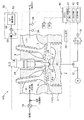
エンジン100は、ピストン2と、ピストン2を収容するシリンダ3とを備え、ピストン2をシリンダ3内で往復運動させると共に、吸気弁4及び排気弁5を開閉動作させて、シリンダ3内に形成された燃焼室1において吸気、圧縮、燃焼・膨張、排気の諸行程を行い、ピストン2の往復動をクランク軸17の回転運動として出力されるものであり、このような構成は、通常の4ストローク内燃機関と変わるところはない。
An embodiment of the present invention will be described with reference to FIGS.
The
このエンジン100は、メタンを主成分とする天然ガスである主燃料MFと空気との混合気MGを吸気路6に形成し、吸気行程において吸気弁4を開状態として吸気路6からその混合気MGを燃焼室1に吸気して、圧縮行程において排気弁5を閉状態としてその吸気した混合気MGを圧縮し、燃焼・膨張行程においてその圧縮した混合気を着火して燃焼させ、排気行程において排気弁5を開状態として燃焼後の排ガスを排気路7に排出する。
尚、混合気MGの当量比は、1未満、好ましくは0.5以上0.7以下の範囲内程度に設定される。
The
The equivalence ratio of the air-fuel mixture MG is set to be less than 1, preferably in the range of 0.5 to 0.7.
燃焼室1には、上記吸気路6から吸気される主燃料MFとは異なり、主燃料MFよりも着火性に優れた液体燃料である軽油や灯油などの副燃料SFを、圧縮行程終了時に燃焼室1に高圧噴射して自己着火させる燃料噴射弁25が設けられている。
Unlike the main fuel MF sucked from the
この燃料噴射弁25は、一般的なディーゼルエンジンなどで用いられている例えばコモンレール方式の燃料噴射機構と同様の構成を採用することができ、高圧縮された状態で供給された副燃料SFを燃焼室1に噴射するように構成される。
The
しかし、そのディーゼルエンジン用の燃料噴射機構は高圧噴射した液体燃料を拡散燃焼させることによりピストンを押し下げるために比較的多くの液体燃料を噴射する点と比較して、この燃料噴射弁25は、副燃料SFの噴射量が微量である点で相違する。
However, the fuel injection mechanism for the diesel engine has a secondary
即ち、本実施形態のエンジン100では、圧縮行程終了時において、燃料噴射弁25から燃焼室1に微量の副燃料SFを高圧噴射して自己着火燃焼させることにより、燃焼・膨張行程において、その副燃料MFの自己着火燃焼により発生した熱エネルギによって吸気路6から吸気された混合気MGが安定して着火されて燃焼し、その燃焼によりピストン2が押し下げられて、運転が継続されるのである。
That is, in the
尚、燃料噴射弁25による副燃料SFの噴射量は、主燃料MFと副燃料SFとの熱量の合計に対する熱量比で0.2%以上5%以下の範囲内好ましくは1%以下の範囲内とされる。
即ち、副燃料SFの噴射量の総熱量に対する熱量比を0.2%よりも小さくすると、その自己着火燃焼により発生する熱量が小さすぎて混合気MGを安定して着火させることができずに失火が発生する場合があり、一方5%よりも大きくすると、その自己着火燃焼により発生する熱量が大きすぎて燃焼室1の最高圧力が過剰に大きくなりノッキング等が発生する場合があり、更に、主燃料MFに対する副燃料SFの消費量が大きくなるから、副燃料SFを貯留しておくタンクなどの大型化により装置の大型化を招いてしまう。
また、副燃料SFの噴射量の総熱量に対する熱量比を1%未満とすることで、上記のような失火及びノッキングを回避しながら、一層の小型化を図ることができる。
The injection amount of the auxiliary fuel SF by the
That is, if the calorie ratio of the injection amount of the auxiliary fuel SF to the total heat amount is smaller than 0.2%, the amount of heat generated by the self-ignition combustion is too small to stably ignite the mixture MG. Misfire may occur. On the other hand, if it is larger than 5%, the amount of heat generated by the self-ignition combustion is too large, the maximum pressure of the
Further, by making the heat quantity ratio of the injection quantity of the auxiliary fuel SF to the total heat quantity less than 1%, further miniaturization can be achieved while avoiding misfire and knocking as described above.
そして、エンジン100は、上記のような構成を採用することにより、主燃料MFとして天然ガス等を用いた当量比0.5〜0.7の混合気MGを、燃料噴射弁25から高圧噴射された微量の副燃料MFの自己着火燃焼により安定して着火させることができるので、燃焼室1における図示平均有効圧力を高くして、高出力且つ高効率化を図ることができる。
The
また、燃料噴射弁25への副燃料SFを供給する副燃料供給手段50について説明を加えると、副燃料SFは、副燃料タンク53に貯留されており、その副燃料SFが、副燃料供給路54において、クランク軸17の回転動力を利用して駆動する燃料ポンプ51により高圧縮され、燃料噴射弁25に供給される。
また、燃料噴射弁25による副燃料SFの噴射量は、燃料噴射弁25自身の作動を調整することにより調整される。尚、この燃料噴射弁25における噴射量は、副燃料供給路54に設けたガバナを調整して、燃料噴射弁25へ供給される副燃料SFの圧力を調整することでも調整することができる。
また、副燃料供給路54には、副燃料SFの流量を計測する流量計52が設けられている。
Further, the auxiliary fuel supply means 50 for supplying the auxiliary fuel SF to the
Further, the injection amount of the sub fuel SF by the
The auxiliary
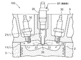
また、本実施形態のエンジン100は、燃焼室1として、シリンダ3の内面とピストン2の頂面とシリンダヘッド9の下面とで規定される主室11と、シリンダヘッド9の中央部(シリンダ3の軸心に沿った部分)に設けられた副室口金20内に形成された副室21とが設けられ、この主室11と副室21とは、上記副室口金20の主室11への突出部に形成された連通孔22を介して連通する。尚、上記副室21の容積比は、燃焼室1全体の2%以上20%以下程度が好ましい。
Further, the
更に、ピストン2の頂面の中央部には、ピストン2が上死点に位置するときに、主室11に突出する上記副室口金20を囲う形態で凹部2aが形成されており、凹部2aにより、圧縮行程においてピストン2が上昇するときに、ピストン2の頂面外周部から凹部2aの中心部に流れるスキッシュが発生する。
Furthermore, a
更に、燃料噴射弁25は、上記副室口金20の上方に設けられて、副室21に副燃料SFを高圧噴射するように構成されている。
Further, the
即ち、このエンジン100は、上記のような構成を採用することにより、主室11に吸気された混合気MGをピストン2の上昇により圧縮して、圧縮された混合気MGを主室11に開口する連通孔22を介して副室21に流入させ、副室21において圧縮された混合気MGに燃料噴射弁25により副燃料SFを噴射して自己着火燃焼させることで火炎を形成し、その火炎を副室21から連通孔22を介して主室11に火炎ジェットFJとして噴射して、この火炎ジェットFJにより主室11の混合気MGを着火させて燃焼させる所謂噴射着火運転を行うように構成されている。
That is, the
エンジン100には、コンピュータからなるエンジン・コントロール・ユニット(以下、ECUと呼ぶ。)40が設けられ、このECU40は、クランク軸17の回転角度を測定するクランク角センサ16の検出結果によりエンジン回転数を監視しながら、そのエンジン回転数が所望の目標回転数範囲内に設定するように、吸気路6に設けられたスロットルバルブ15の開度調整により燃焼室1への混合気MGの吸気量を調整するエンジン回転数設定手段41として機能するように構成されている。
The
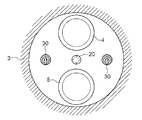
エンジン100は、図2に示すように、燃料噴射弁25が燃焼室1の中央部に配置され、複数具体的には2個の点火プラグ30が燃焼室1の中央部を中心に対称配置されており、更に、燃料噴射弁25は副室21に配置され、複数の点火プラグ30は主室11に配置されている。また、これら点火プラグ30は、例えば起動運転時や無負荷運転時等の燃焼室1において副燃料SFの自己着火や混合気MGの着火が安定していないときに、ECU40により作動されて、主室11に吸気された混合気MGを安定して火花点火して燃焼させるものである。
As shown in FIG. 2, in the
エンジン回転数設定手段41によりエンジン回転数を所定の目標回転数範囲内に設定するように構成しても、急激な負荷変動等により、エンジン回転数が目標回転数範囲外に変動する場合があるが、エンジン100においては、そのようなエンジン回転数の過剰な変動を回避するように構成されている。以下、その詳細構成について説明を加える。
Even if the engine speed is set within the predetermined target speed range by the engine speed setting means 41, the engine speed may fluctuate outside the target speed range due to a sudden load fluctuation or the like. However, the
ECU40は、エンジン負荷36の低下速度が許容速度を超える負荷急低下状態若しくはその負荷急低下状態等に起因してクランク角センサ16の検出結果から認識されるエンジン回転数が目標回転数範囲を超える高回転数状態、又は、エンジン負荷36の上昇速度が許容速度を超える負荷急上昇状態若しくはその負荷急上昇状態等に起因してエンジン回転数が目標回転数範囲を下回る低回転数状態を判定する判定手段42として機能するように構成されている。更に、ECU40は、上記判定手段42により負荷急低下状態若しくは高回転数状態を判定したときにエンジン回転数の過剰な上昇を回避するための回転数上昇回避処理を行い、一方、上記判定手段42により負荷急上昇状態若しくは低回転数状態を判定したときにエンジン回転数の過剰な低下を回避するための回転数低下回避処理を行う処理手段43として機能するように構成されている。
The
即ち、処理手段43は、上記判定手段42により負荷急低下状態若しくは高回転数状態を判定したときに、燃料噴射弁25による副燃料SFの噴射量を瞬時に低下若しくは停止させるように上記回転数上昇回避処理を行って、副燃料の自己着火燃焼により発生する熱エネルギを低下若しくは無くして、エンジン回転数がそれ以上増加してエンジンが損傷することを抑制して、エンジン回転数を目標回転数範囲内に低下させる。
That is, the processing means 43, when the determination means 42 determines a sudden load drop state or a high rotation speed state, the rotation speed so as to instantaneously decrease or stop the injection amount of the sub fuel SF by the
一方、処理手段43は、上記判定手段42により負荷急上昇状態若しくは低回転数状態を判定したときに、主燃料MFの供給量を増加させることで燃焼室1に吸気される混合気MGの当量比を増加させると共に、燃料噴射弁25からの副燃料SFの噴射量を低下させるように上記回転数低下回避処理を行って、燃焼室1の燃焼を活性化し、エンジン回転数がそれ以上低下してエンジンが停止することを抑制して、エンジン回転数を目標回転数範囲内に上昇させる。
また、上記回転数低下処理において、上記副燃料SFの噴射量を低下させるので、混合気MGの当量比の増加に起因する副室口金20等の熱損傷が抑制される。
尚、本実施形態では、上記回転数低下回避処理において、混合気MGの当量比を当初0.5程度であったものを0.7程度に増加させ、副燃料SFの噴射量は、その総熱量に対する熱量比で、当初1%程度であったものを0.5%程度に低下させる。
On the other hand, the processing means 43 increases the supply ratio of the main fuel MF to increase the equivalence ratio of the air-fuel mixture MG that is taken into the
Further, since the injection amount of the auxiliary fuel SF is reduced in the rotation speed reduction process, thermal damage to the
In the present embodiment, in the rotation speed reduction avoiding process, the equivalence ratio of the air-fuel mixture MG is initially increased from about 0.5 to about 0.7, and the injection amount of the auxiliary fuel SF is set to the total amount. The ratio of heat quantity to heat quantity, which was originally about 1%, is reduced to about 0.5%.
また、上記処理手段43は、エンジン100が、燃焼室1を複数備えた多気筒式に構成されている場合には、全ての燃焼室1に対して上記回転数上昇回避処理又は上記回転数低下回避処理を行うことでエンジン回転数の過剰な低下又は上昇等が発生することを抑制するために、複数の燃焼室1の内の予め決定してある一部の燃焼室1に対して上記回転数上昇回避処理又は上記回転数低下回避処理を行うように構成される。
Further, when the
また、処理手段43は、回転数低下回避処理において、燃料噴射弁25からの副燃料SFの噴射量を低下させることで混合気MGに対する着火性が低下することを防止するために、点火プラグ30を作動させるように構成されている。
In addition, the processing means 43 prevents the ignition plug 30 from igniting the air-fuel mixture MG by reducing the injection amount of the sub fuel SF from the
〔別実施形態〕
(1)上記実施の形態では、回転数上昇回避処理における副燃料SFの噴射量の低下幅は、エンジン回転数の過剰の上昇を回避できる範囲内で適宜設定可能である。
[Another embodiment]
(1) In the above embodiment, the amount of decrease in the injection amount of the auxiliary fuel SF in the rotation speed increase avoidance process can be set as appropriate within a range in which an excessive increase in engine speed can be avoided.
(2)上記実施の形態では、燃料噴射弁25を燃焼室1の中央部に配置された副室21に配置し、更に、点火プラグ30を燃焼室1としての主室11の中央部を中心に対称配置したが、上記燃料噴射弁25及び点火プラグ30の配置は適宜改変可能である。
また、点火プラグ30は設けなくても構わない。
(2) In the above embodiment, the
Further, the
(3)上記実施の形態では、燃焼室1として主室11及び副室21を設けたが、別に、副室21を設けることなく、主室11のみで燃焼室1を構成しても構わない。
(3) Although the
(4)上記実施の形態では、主燃料MFとして天然ガスを、副燃料SFとして軽油や灯油を用いたが、別に、主燃料MF及び副燃料SFは適宜改変可能である。尚、特に、副燃料SFについては、燃焼室1に高圧状態で噴射して自己着火させるので、着火性に優れた液体燃料を利用することが好ましい。
(4) In the above embodiment, natural gas is used as the main fuel MF, and light oil or kerosene is used as the auxiliary fuel SF. However, the main fuel MF and the auxiliary fuel SF can be modified as appropriate. In particular, since the auxiliary fuel SF is injected into the
1:燃焼室
11:主室(燃焼室)
15:スロットルバルブ
16:クランク角センサ
21:副室(燃焼室)
22:連通孔
25:燃料噴射弁
30:点火プラグ
36:エンジン負荷
40:エンジン・コントロール・ユニット(ECU)
41:エンジン回転数設定手段
42:判定手段
43:処理手段
50:副燃料供給手段
100:エンジン
MF:主燃料
SF:副燃料
MG:混合気
1: Combustion chamber 11: Main chamber (combustion chamber)
15: Throttle valve 16: Crank angle sensor 21: Sub chamber (combustion chamber)
22: Communication hole 25: Fuel injection valve 30: Spark plug 36: Engine load 40: Engine control unit (ECU)
41: Engine speed setting means 42: Determination means 43: Processing means 50: Sub fuel supply means 100: Engine MF: Main fuel SF: Sub fuel MG: Air-fuel mixture
Claims (4)
エンジン回転数が前記目標回転数範囲を超える高回転数状態を判定する判定手段と、
前記判定手段で前記高回転数状態を判定したときに、前記燃料噴射弁による副燃料の噴射量を低下若しくは停止させる回転数上昇回避処理を行う処理手段とを備えたエンジン。 In a combustion chamber in which an air-fuel mixture of main fuel and oxygen-containing gas is compressed, it is configured to perform an injection ignition operation of igniting the air-fuel mixture by injecting auxiliary fuel from a fuel injection valve and performing self-ignition combustion, An engine having an engine speed setting means for adjusting an intake amount of an air-fuel mixture into a combustion chamber and setting an engine speed within a target speed range,
Determining means for determining a high engine speed state in which the engine engine speed exceeds the target engine speed range;
An engine comprising: processing means for performing a speed increase avoidance process for reducing or stopping the injection amount of the auxiliary fuel by the fuel injection valve when the determination means determines the high speed state.
エンジン負荷の低下速度が許容速度を超える負荷急低下状態を判定する判定手段と、
前記判定手段で前記負荷急低下状態を判定したときに、前記燃料噴射弁による副燃料の噴射量を低下若しくは停止させる回転数上昇回避処理を行う処理手段とを備えたエンジン。 In a combustion chamber in which an air-fuel mixture of main fuel and oxygen-containing gas is compressed, it is configured to perform an injection ignition operation of igniting the air-fuel mixture by injecting auxiliary fuel from a fuel injection valve and performing self-ignition combustion, An engine having an engine speed setting means for adjusting an intake amount of an air-fuel mixture into a combustion chamber and setting an engine speed within a target speed range,
A determination means for determining a sudden load decrease state in which the engine load decrease speed exceeds an allowable speed;
An engine comprising: processing means for performing a speed increase avoidance process for reducing or stopping the injection amount of the auxiliary fuel by the fuel injection valve when the determination means determines the sudden load drop state.
前記燃料噴射弁が前記副室に配置されている請求項1又は2に記載のエンジン。 The combustion chamber includes a main chamber formed in a cylinder, and a sub chamber formed in a cylinder head and communicating with the main chamber.
The engine according to claim 1, wherein the fuel injection valve is disposed in the sub chamber.
前記処理手段が、一部の前記燃焼室に対してのみ前記回転数上昇回避処理を行うように構成されている請求項1から3の何れか1項に記載のエンジン。
A plurality of combustion chambers are provided to form a multi-cylinder type,
The engine according to any one of claims 1 to 3, wherein the processing unit is configured to perform the rotation speed increase avoidance process only on a part of the combustion chambers.
Priority Applications (1)
| Application Number | Priority Date | Filing Date | Title |
|---|---|---|---|
| JP2004118013A JP2005299542A (en) | 2004-04-13 | 2004-04-13 | engine |
Applications Claiming Priority (1)
| Application Number | Priority Date | Filing Date | Title |
|---|---|---|---|
| JP2004118013A JP2005299542A (en) | 2004-04-13 | 2004-04-13 | engine |
Publications (1)
| Publication Number | Publication Date |
|---|---|
| JP2005299542A true JP2005299542A (en) | 2005-10-27 |
Family
ID=35331390
Family Applications (1)
| Application Number | Title | Priority Date | Filing Date |
|---|---|---|---|
| JP2004118013A Pending JP2005299542A (en) | 2004-04-13 | 2004-04-13 | engine |
Country Status (1)
| Country | Link |
|---|---|
| JP (1) | JP2005299542A (en) |
Cited By (3)
| Publication number | Priority date | Publication date | Assignee | Title |
|---|---|---|---|---|
| JP2015232280A (en) * | 2014-06-09 | 2015-12-24 | マツダ株式会社 | Multiple-fuel engine fuel injection control unit |
| JP2017510745A (en) * | 2014-03-17 | 2017-04-13 | ウッドワード, インコーポレーテッドWoodward, Inc. | Use of pre-chamber for dual fuel engine |
| JP2021095869A (en) * | 2019-12-17 | 2021-06-24 | Ygk通商株式会社 | Power generation gas engine |
-
2004
- 2004-04-13 JP JP2004118013A patent/JP2005299542A/en active Pending
Cited By (3)
| Publication number | Priority date | Publication date | Assignee | Title |
|---|---|---|---|---|
| JP2017510745A (en) * | 2014-03-17 | 2017-04-13 | ウッドワード, インコーポレーテッドWoodward, Inc. | Use of pre-chamber for dual fuel engine |
| JP2015232280A (en) * | 2014-06-09 | 2015-12-24 | マツダ株式会社 | Multiple-fuel engine fuel injection control unit |
| JP2021095869A (en) * | 2019-12-17 | 2021-06-24 | Ygk通商株式会社 | Power generation gas engine |
Similar Documents
| Publication | Publication Date | Title |
|---|---|---|
| JP4100401B2 (en) | Internal combustion engine | |
| JP3991789B2 (en) | An internal combustion engine that compresses and ignites the mixture. | |
| CN101473126B (en) | Multifuel internal combustion engine | |
| US6427643B1 (en) | Internal combustion engine with variable compression ratio | |
| WO2009130777A1 (en) | Multifuel internal-combustion engine | |
| JP4715753B2 (en) | Internal combustion engine | |
| JP2009108777A (en) | Compression ignition internal combustion engine | |
| JP5922830B1 (en) | Gas engine | |
| JP5192177B2 (en) | Sub-chamber engine | |
| JP4386781B2 (en) | engine | |
| JP4073315B2 (en) | Sub-chamber engine | |
| JP4737045B2 (en) | Multi-fuel internal combustion engine | |
| JP2005232988A (en) | Subsidiary chamber type engine | |
| JP3953346B2 (en) | Sub-chamber lean combustion gas engine | |
| JP2005299542A (en) | engine | |
| JP4835279B2 (en) | Multi-fuel internal combustion engine | |
| JP4229795B2 (en) | Premixed compression ignition engine and operation control method thereof | |
| JP3747519B2 (en) | Direct cylinder injection spark ignition engine | |
| JPH11324805A (en) | Precombustion chamber type gas engine | |
| JP2005299541A (en) | engine | |
| JP2024038712A (en) | Internal combustion engine control device | |
| JP4145177B2 (en) | Engine and operation method thereof | |
| JP4844316B2 (en) | Multi-fuel internal combustion engine | |
| JP2007315357A (en) | Multi-fuel internal combustion engine | |
| JP2000064838A (en) | Pilot ignition gas engine |
Legal Events
| Date | Code | Title | Description |
|---|---|---|---|
| A621 | Written request for application examination |
Free format text: JAPANESE INTERMEDIATE CODE: A621 Effective date: 20060831 |
|
| A977 | Report on retrieval |
Free format text: JAPANESE INTERMEDIATE CODE: A971007 Effective date: 20080625 |
|
| A131 | Notification of reasons for refusal |
Free format text: JAPANESE INTERMEDIATE CODE: A131 Effective date: 20080626 |
|
| A02 | Decision of refusal |
Free format text: JAPANESE INTERMEDIATE CODE: A02 Effective date: 20081030 |