JP2005299525A - Control device for internal combustion engine - Google Patents
Control device for internal combustion engine Download PDFInfo
- Publication number
- JP2005299525A JP2005299525A JP2004117646A JP2004117646A JP2005299525A JP 2005299525 A JP2005299525 A JP 2005299525A JP 2004117646 A JP2004117646 A JP 2004117646A JP 2004117646 A JP2004117646 A JP 2004117646A JP 2005299525 A JP2005299525 A JP 2005299525A
- Authority
- JP
- Japan
- Prior art keywords
- injection valve
- fuel
- hydrogen
- cylinder
- internal combustion
- Prior art date
- Legal status (The legal status is an assumption and is not a legal conclusion. Google has not performed a legal analysis and makes no representation as to the accuracy of the status listed.)
- Withdrawn
Links
Images
Classifications
-
- F—MECHANICAL ENGINEERING; LIGHTING; HEATING; WEAPONS; BLASTING
- F02—COMBUSTION ENGINES; HOT-GAS OR COMBUSTION-PRODUCT ENGINE PLANTS
- F02D—CONTROLLING COMBUSTION ENGINES
- F02D41/00—Electrical control of supply of combustible mixture or its constituents
- F02D41/0025—Controlling engines characterised by use of non-liquid fuels, pluralities of fuels, or non-fuel substances added to the combustible mixtures
-
- F—MECHANICAL ENGINEERING; LIGHTING; HEATING; WEAPONS; BLASTING
- F02—COMBUSTION ENGINES; HOT-GAS OR COMBUSTION-PRODUCT ENGINE PLANTS
- F02D—CONTROLLING COMBUSTION ENGINES
- F02D19/00—Controlling engines characterised by their use of non-liquid fuels, pluralities of fuels, or non-fuel substances added to the combustible mixtures
- F02D19/06—Controlling engines characterised by their use of non-liquid fuels, pluralities of fuels, or non-fuel substances added to the combustible mixtures peculiar to engines working with pluralities of fuels, e.g. alternatively with light and heavy fuel oil, other than engines indifferent to the fuel consumed
- F02D19/08—Controlling engines characterised by their use of non-liquid fuels, pluralities of fuels, or non-fuel substances added to the combustible mixtures peculiar to engines working with pluralities of fuels, e.g. alternatively with light and heavy fuel oil, other than engines indifferent to the fuel consumed simultaneously using pluralities of fuels
- F02D19/081—Adjusting the fuel composition or mixing ratio; Transitioning from one fuel to the other
-
- F—MECHANICAL ENGINEERING; LIGHTING; HEATING; WEAPONS; BLASTING
- F02—COMBUSTION ENGINES; HOT-GAS OR COMBUSTION-PRODUCT ENGINE PLANTS
- F02D—CONTROLLING COMBUSTION ENGINES
- F02D41/00—Electrical control of supply of combustible mixture or its constituents
- F02D41/0025—Controlling engines characterised by use of non-liquid fuels, pluralities of fuels, or non-fuel substances added to the combustible mixtures
- F02D41/0027—Controlling engines characterised by use of non-liquid fuels, pluralities of fuels, or non-fuel substances added to the combustible mixtures the fuel being gaseous
-
- F—MECHANICAL ENGINEERING; LIGHTING; HEATING; WEAPONS; BLASTING
- F02—COMBUSTION ENGINES; HOT-GAS OR COMBUSTION-PRODUCT ENGINE PLANTS
- F02D—CONTROLLING COMBUSTION ENGINES
- F02D41/00—Electrical control of supply of combustible mixture or its constituents
- F02D41/30—Controlling fuel injection
- F02D41/3094—Controlling fuel injection the fuel injection being effected by at least two different injectors, e.g. one in the intake manifold and one in the cylinder
-
- F—MECHANICAL ENGINEERING; LIGHTING; HEATING; WEAPONS; BLASTING
- F02—COMBUSTION ENGINES; HOT-GAS OR COMBUSTION-PRODUCT ENGINE PLANTS
- F02D—CONTROLLING COMBUSTION ENGINES
- F02D19/00—Controlling engines characterised by their use of non-liquid fuels, pluralities of fuels, or non-fuel substances added to the combustible mixtures
- F02D19/06—Controlling engines characterised by their use of non-liquid fuels, pluralities of fuels, or non-fuel substances added to the combustible mixtures peculiar to engines working with pluralities of fuels, e.g. alternatively with light and heavy fuel oil, other than engines indifferent to the fuel consumed
- F02D19/0663—Details on the fuel supply system, e.g. tanks, valves, pipes, pumps, rails, injectors or mixers
- F02D19/0686—Injectors
- F02D19/0692—Arrangement of multiple injectors per combustion chamber
-
- Y—GENERAL TAGGING OF NEW TECHNOLOGICAL DEVELOPMENTS; GENERAL TAGGING OF CROSS-SECTIONAL TECHNOLOGIES SPANNING OVER SEVERAL SECTIONS OF THE IPC; TECHNICAL SUBJECTS COVERED BY FORMER USPC CROSS-REFERENCE ART COLLECTIONS [XRACs] AND DIGESTS
- Y02—TECHNOLOGIES OR APPLICATIONS FOR MITIGATION OR ADAPTATION AGAINST CLIMATE CHANGE
- Y02T—CLIMATE CHANGE MITIGATION TECHNOLOGIES RELATED TO TRANSPORTATION
- Y02T10/00—Road transport of goods or passengers
- Y02T10/10—Internal combustion engine [ICE] based vehicles
- Y02T10/30—Use of alternative fuels, e.g. biofuels
Landscapes
- Engineering & Computer Science (AREA)
- Chemical & Material Sciences (AREA)
- Combustion & Propulsion (AREA)
- Mechanical Engineering (AREA)
- General Engineering & Computer Science (AREA)
- Oil, Petroleum & Natural Gas (AREA)
- Combined Controls Of Internal Combustion Engines (AREA)
- Output Control And Ontrol Of Special Type Engine (AREA)
- Electrical Control Of Air Or Fuel Supplied To Internal-Combustion Engine (AREA)
Abstract
【課題】 この発明は、内燃機関の制御装置に関し、運転状態に応じた適切な手法で水素を供給することができ、これにより、機関性能を向上させることを目的とする。
【解決手段】 吸気ポート18に、ガソリンを噴射するガソリン噴射弁26と、水素を噴射する水素燃料ポート噴射弁28とを設ける。シリンダヘッド14に、水素を筒内に噴射する水素燃料筒内噴射弁30を設ける。内燃機関10の運転状態に応じて、用いる噴射弁を選択する。通常運転時には、ガソリン噴射弁26および水素燃料ポート噴射弁28を選択する。高負荷時には、ガソリン噴射弁26および水素燃料筒内噴射弁30を選択する。また、始動時には、水素燃料筒内噴射弁30のみを選択する。
【選択図】 図1
The present invention relates to a control device for an internal combustion engine, and can supply hydrogen by an appropriate method according to an operating state, thereby improving engine performance.
SOLUTION: An intake port 18 is provided with a gasoline injection valve 26 for injecting gasoline and a hydrogen fuel port injection valve 28 for injecting hydrogen. The cylinder head 14 is provided with a hydrogen fuel cylinder injection valve 30 that injects hydrogen into the cylinder. The injection valve to be used is selected according to the operating state of the internal combustion engine 10. During normal operation, the gasoline injection valve 26 and the hydrogen fuel port injection valve 28 are selected. When the load is high, the gasoline injection valve 26 and the hydrogen fuel in-cylinder injection valve 30 are selected. At the time of start-up, only the hydrogen fuel cylinder injection valve 30 is selected.
[Selection] Figure 1
Description
この発明は、内燃機関の制御装置に係り、特に、ガソリン等の主燃料と水素燃料の双方を燃料として利用する内燃機関の制御装置に関する。 The present invention relates to a control device for an internal combustion engine, and more particularly to a control device for an internal combustion engine that uses both main fuel such as gasoline and hydrogen fuel as fuel.
従来、例えば特開平9−195857号公報には、ガソリンを吸気ポートに噴射するガソリン噴射弁と、水素を吸気ポートに噴射する水素ポート噴射弁とを備える内燃機関が開示されている。また、従来、例えば特開平7−63128号公報には、ガソリンを吸気ポートに噴射するガソリン噴射弁と、水素を筒内に噴射する水素筒内噴射弁とを備える内燃機関が開示されている。水素を燃料として用いると、燃焼速度がガソリンの場合に比して格段に速くなる。このため、上記従来の技術の何れにおいても、ガソリンを主燃料として用いつつ、更に水素を添加することにより、燃焼状態を改善させることができる。 Conventionally, for example, Japanese Patent Application Laid-Open No. 9-195857 discloses an internal combustion engine that includes a gasoline injection valve that injects gasoline into an intake port and a hydrogen port injection valve that injects hydrogen into an intake port. Conventionally, for example, Japanese Patent Application Laid-Open No. 7-63128 discloses an internal combustion engine including a gasoline injection valve that injects gasoline into an intake port and a hydrogen in-cylinder injection valve that injects hydrogen into the cylinder. When hydrogen is used as a fuel, the combustion speed is much faster than in the case of gasoline. For this reason, in any of the above conventional techniques, the combustion state can be improved by adding hydrogen while using gasoline as the main fuel.
上記従来の技術のようにガソリンを主燃料とする内燃機関において、水素を燃料として利用すれば、内燃機関の運転状態に応じて様々なメリットを得ることが可能である。しかしながら、上述した従来の技術のように、水素を供給する燃料噴射弁を吸気ポートまたは筒内の何れか一方に備える構成では、主燃料と共に、あるいは単独で水素を燃料として用いるメリットを生かしきれない。 In the internal combustion engine using gasoline as the main fuel as in the above-described conventional technology, if hydrogen is used as the fuel, various merits can be obtained according to the operating state of the internal combustion engine. However, in the configuration in which the fuel injection valve for supplying hydrogen is provided in either the intake port or the cylinder as in the conventional technique described above, the advantage of using hydrogen alone as the fuel together with the main fuel cannot be utilized. .
この発明は、上述のような課題を解決するためになされたもので、運転状態に応じた適切な手法で水素を供給することができ、これにより、機関性能を向上させることのできる内燃機関の制御装置を提供することを目的とする。 The present invention has been made to solve the above-described problems, and can supply hydrogen by an appropriate technique according to the operating state, thereby improving the engine performance. An object is to provide a control device.
第1の発明は、上記の目的を達成するため、主燃料を噴射する主燃料噴射弁と、
水素燃料を吸気ポートに噴射する水素燃料ポート噴射弁と、
水素燃料を筒内に噴射する水素燃料筒内噴射弁とを備え、
内燃機関の運転状態に応じて、前記主燃料噴射弁、前記水素燃料ポート噴射弁、および前記水素燃料筒内噴射弁の中から燃料噴射に用いる噴射弁を選択する噴射弁選択手段と、
前記噴射弁選択手段により選択された噴射弁を用いて燃料噴射を実行する燃料噴射実行手段と、を備えることを特徴とする。
In order to achieve the above object, a first invention is a main fuel injection valve that injects main fuel;
A hydrogen fuel port injection valve for injecting hydrogen fuel into the intake port;
A hydrogen fuel in-cylinder injection valve for injecting hydrogen fuel into the cylinder;
An injection valve selection means for selecting an injection valve to be used for fuel injection from the main fuel injection valve, the hydrogen fuel port injection valve, and the hydrogen fuel in-cylinder injection valve according to the operating state of the internal combustion engine;
Fuel injection execution means for executing fuel injection using the injection valve selected by the injection valve selection means.
また、第2の発明は、第1の発明において、前記噴射弁選択手段は、内燃機関の始動時には、前記水素燃料筒内噴射弁のみによる燃料噴射を選択し、
前記燃料噴射実行手段は、成層運転が実現されるように燃料噴射を実行することを特徴とする。
In a second aspect based on the first aspect, the injection valve selection means selects fuel injection only by the hydrogen fuel in-cylinder injection valve when starting the internal combustion engine,
The fuel injection execution means executes fuel injection so as to realize a stratified operation.
また、第3の発明は、第1の発明において、前記主燃料噴射弁は、主燃料を吸気ポートに噴射する噴射弁であり、
前記噴射弁選択手段は、内燃機関の通常運転時には、前記主燃料噴射弁と前記水素燃料ポート噴射弁とによる燃料噴射を選択することを特徴とする。
In a third aspect based on the first aspect, the main fuel injection valve is an injection valve that injects main fuel into the intake port,
The injection valve selection means selects fuel injection by the main fuel injection valve and the hydrogen fuel port injection valve during normal operation of the internal combustion engine.
また、第4の発明は、第3の発明において、前記噴射弁選択手段は、加速が開始された時点から所定の噴射弁変更期間が経過するまでの間は、前記主燃料噴射弁と前記水素燃料筒内噴射弁とによる燃料噴射を選択することを特徴とする。 According to a fourth aspect of the present invention based on the third aspect, the injection valve selection means is arranged such that the main fuel injection valve and the hydrogen are in a range from when acceleration is started until a predetermined injection valve change period has elapsed. The fuel injection by the fuel cylinder injection valve is selected.
また、第5の発明は、第1の発明において、前記噴射弁選択手段は、内燃機関の高負荷時には、前記主燃料噴射弁と前記水素燃料筒内噴射弁とによる燃料噴射を選択し、
前記燃料噴射実行手段は、吸気弁が閉弁した後に、前記水素燃料筒内噴射弁からの燃料噴射を開始することを特徴とする。
In a fifth aspect based on the first aspect, the injection valve selection means selects fuel injection by the main fuel injection valve and the hydrogen fuel in-cylinder injection valve when the internal combustion engine is at a high load,
The fuel injection execution means starts fuel injection from the hydrogen fuel in-cylinder injection valve after the intake valve is closed.
また、第6の発明は、第1の発明において、前記噴射弁選択手段は、ノッキングが検出された場合には、前記主燃料噴射弁と前記水素燃料筒内噴射弁とによる燃料噴射を選択し、
前記燃料噴射実行手段は、吸気弁が閉弁した後に、前記水素燃料筒内噴射弁からの燃料噴射を開始することを特徴とする。
In a sixth aspect based on the first aspect, the injection valve selection means selects fuel injection by the main fuel injection valve and the hydrogen fuel in-cylinder injection valve when knocking is detected. ,
The fuel injection execution means starts fuel injection from the hydrogen fuel in-cylinder injection valve after the intake valve is closed.
また、第7の発明は、第1の発明において、前記噴射弁選択手段は、排気温度が所定の上限値を越えた場合には、前記主燃料噴射弁と前記水素燃料筒内噴射弁とによる燃料噴射を選択し、
前記燃料噴射実行手段は、吸気弁が閉弁した後に、前記水素燃料筒内噴射弁からの燃料噴射を開始することを特徴とする。
Further, according to a seventh aspect based on the first aspect, the injection valve selecting means uses the main fuel injection valve and the hydrogen fuel in-cylinder injection valve when the exhaust gas temperature exceeds a predetermined upper limit value. Select fuel injection,
The fuel injection execution means starts fuel injection from the hydrogen fuel in-cylinder injection valve after the intake valve is closed.
第1の発明によれば、内燃機関の運転状態に応じて、燃料噴射に用いる噴射弁を選択することにより、内燃機関の様々な運転状態に対して、適切な手法で水素を供給することができる。このため、本発明によれば、主燃料と共に、あるいは単独で水素を燃料として用いるメリットを最大限に得ることができ、内燃機関の性能を向上させることができる。 According to the first invention, by selecting an injection valve used for fuel injection according to the operating state of the internal combustion engine, hydrogen can be supplied in an appropriate manner with respect to various operating states of the internal combustion engine. it can. For this reason, according to the present invention, the merit of using hydrogen as the fuel alone or with the main fuel can be maximized, and the performance of the internal combustion engine can be improved.
第2の発明によれば、始動時には、水素燃料筒内噴射弁が選択される。水素を燃料として成層運転を行えば、ガソリンなどの主燃料の場合に比して大幅に高い空気過剰率で希薄燃焼運転を行うことができ、また、未燃HCが排出されることもない。このため、本発明によれば、始動時に、水素燃料筒内噴射弁を選択して、内燃機関を高効率に運転することができる。 According to the second invention, at the time of start-up, the hydrogen fuel in-cylinder injection valve is selected. When stratified operation is performed using hydrogen as a fuel, lean combustion operation can be performed with an air excess rate significantly higher than that of main fuel such as gasoline, and unburned HC is not discharged. Therefore, according to the present invention, the internal combustion engine can be operated with high efficiency by selecting the hydrogen fuel in-cylinder injection valve at the time of starting.
第3の発明によれば、通常運転時には、主燃料噴射弁と水素燃料ポート噴射弁とが選択される。この際、水素が筒内ではなく吸気ポート内に噴射されると、吸気ポート内に噴射された水素と主燃料との混合状態、および、それらと空気との混合状態を良くすることができる。このため、本発明によれば、筒内に直接水素を噴射する場合に比して、更に希薄燃焼運転が可能な限界を延ばすことができ、その結果として、更なる燃費性能の向上や排気ガスの清浄化を実現することができる。 According to the third invention, the main fuel injection valve and the hydrogen fuel port injection valve are selected during normal operation. At this time, if hydrogen is injected into the intake port instead of into the cylinder, the mixed state of hydrogen injected into the intake port and the main fuel and the mixed state of these and air can be improved. For this reason, according to the present invention, it is possible to extend the limit at which lean-burn operation can be further performed as compared with the case where hydrogen is directly injected into the cylinder, and as a result, further improvement of fuel consumption performance and exhaust gas can be achieved. Can be realized.
第4の発明によれば、加速の初期時には、主燃料噴射弁と水素燃料筒内噴射弁とが選択される。水素燃料噴射弁は、水素燃料ポート噴射弁に比して噴射圧力が高い。このため、加速時に水素燃料筒内噴射弁が選択されることで、水素燃料ポート噴射弁を使用する場合に比して、高い追従性で水素の噴射量を増量させることができる。このため、本発明によれば、加速時に、良好なレスポンスで水素を供給することができる。 According to the fourth invention, at the initial stage of acceleration, the main fuel injection valve and the hydrogen fuel in-cylinder injection valve are selected. The hydrogen fuel injection valve has a higher injection pressure than the hydrogen fuel port injection valve. For this reason, by selecting the hydrogen fuel in-cylinder injection valve at the time of acceleration, it is possible to increase the hydrogen injection amount with high followability as compared with the case of using the hydrogen fuel port injection valve. For this reason, according to the present invention, hydrogen can be supplied with a good response during acceleration.
第5の発明によれば、高負荷時には、主燃料噴射弁と水素燃料筒内噴射弁とが選択される。この際、吸気弁の閉弁後に水素を筒内に供給されるため、吸入空気量が減少しない。このため、本発明によれば、高負荷時に、水素添加による燃焼改善効果が得られることで、トルクを向上させることができる。 According to the fifth aspect of the invention, the main fuel injection valve and the hydrogen fuel in-cylinder injection valve are selected at the time of high load. At this time, since the hydrogen is supplied into the cylinder after the intake valve is closed, the intake air amount does not decrease. For this reason, according to the present invention, it is possible to improve the torque by obtaining the combustion improvement effect by hydrogenation at the time of high load.
第6の発明によれば、ノッキングが検出された場合には、主燃料噴射弁と水素燃料筒内噴射弁とが選択される。このため、本発明によれば、水素が供給される際に吸入空気量が減少しないため、トルクを減少させることなく、ノッキングを解消することができる。 According to the sixth aspect, when knocking is detected, the main fuel injection valve and the hydrogen fuel in-cylinder injection valve are selected. Therefore, according to the present invention, since the intake air amount does not decrease when hydrogen is supplied, knocking can be eliminated without reducing the torque.
第7の発明によれば、排気温度が所定の上限値を越えた場合には、主燃料噴射弁と水素燃料筒内噴射弁とが選択される。このため、本発明によれば、水素が供給される際に吸入空気量が減少しないため、トルクを減少させることなく、排気温度を低下させることができ、これにより、触媒を保護することができる。 According to the seventh aspect, when the exhaust temperature exceeds a predetermined upper limit value, the main fuel injection valve and the hydrogen fuel in-cylinder injection valve are selected. For this reason, according to the present invention, since the amount of intake air does not decrease when hydrogen is supplied, the exhaust temperature can be lowered without reducing the torque, and thus the catalyst can be protected. .
実施の形態1.
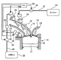
図1は、本発明の実施の形態1の内燃機関10の構成を説明するための図である。内燃機関10の筒内には、その内部を往復移動するピストン12が設けられている。また、内燃機関10は、シリンダヘッド14を備えている。ピストン12とシリンダヘッド14との間には、燃焼室16が形成されている。燃焼室16には、吸気ポート18および排気ポート20が連通している。吸気ポート18および排気ポート20には、それぞれ吸気弁22および排気弁24が配置されている。
Embodiment 1 FIG.
FIG. 1 is a diagram for explaining a configuration of an
吸気ポート18には、ポート内にガソリンを噴射するガソリン噴射弁26が配置されている。また、吸気ポート18には、ポート内に水素を噴射する水素燃料ポート噴射弁28が配置されている。更に、シリンダヘッド14には、筒内に水素を噴射する水素燃料筒内噴射弁30が配置されている。
The
ガソリン噴射弁26には、ガソリン供給管32を介してガソリンタンク34が連通している。ガソリン供給管32は、ガソリン噴射弁26とガソリンタンク34との間に、ポンプ36を備えている。ポンプ36は、ガソリン噴射弁26に所定の圧力でガソリンを供給することができる。このため、ガソリン噴射弁26は、外部から供給される駆動信号を受けて開弁することにより、その開弁の時間に応じた量のガソリンを吸気ポート18内に噴射することができる。
A
本実施形態のシステムは、気体状態にある水素を高圧で貯留するための水素タンク38を備えている。水素タンク38には、水素供給管40が連通している。水素供給管40は、その途中の分岐点42で分岐された後に、それぞれ水素燃料ポート噴射弁28と水素燃料筒内噴射弁30とに連通している。尚、本実施形態のシステムでは、水素燃料ポート噴射弁28および水素燃料筒内噴射弁30に供給される水素燃料として、外部から水素タンク38内に充填される水素ガスを使用しているが、これらの噴射弁に供給される水素燃料はこれに限定されるものではなく、車両上で生成、あるいは外部より供給される高濃度の水素を含む水素リッチガスを使用するものであってもよい。
The system of this embodiment includes a
水素供給管40には、水素タンク38と分岐点42との間に、1次レギュレータ44が配置されており、分岐点42と水素燃料ポート噴射弁28との間に、2次レギュレータ46が配置されている。このような構成によれば、水素燃料筒内噴射弁30には、1次レギュレータ44により減圧された所定の圧力で、水素タンク38内にある水素が供給される。また、水素燃料ポート噴射弁28には、更に2次レギュレータ46により減圧された所定の圧力で、水素が供給される。このため、水素燃料筒内噴射弁30および水素燃料ポート噴射弁28は、外部から供給される駆動信号を受けて開弁することにより、その開弁の時間に応じた量の水素を、それぞれ筒内および吸気ポート18内に噴射することができる。
In the
また、水素供給管40には、分岐点42と水素燃料筒内噴射弁30との間に、燃圧センサ48が配置されている。燃圧センサ48は、水素燃料筒内噴射弁30に供給される水素の圧力に応じた出力を発するセンサである。水素燃料筒内噴射弁30には、水素燃料ポート噴射弁28に比して高圧の水素が供給されることとなる。本実施形態のシステムでは、燃圧センサ48が発する出力に基づいて1次レギュレータ44を制御することとしている。このため、水素タンク38から供給される水素の圧力が変動する場合であっても、水素燃料筒内噴射弁30に安定した圧力で水素を供給することができる。
In the
本実施形態のシステムは、ECU50を備えている。ECU50には、上述した燃圧センサ48に加え、内燃機関10の運転状態を把握すべく、ノッキングの発生を検知するKCSセンサや、スロットル開度、機関回転数、排気温度、冷却水温度、潤滑油温度、触媒床温度などを検出するための各種センサ(図示省略する)が接続されている。また、ECU50には、上述したガソリン噴射弁26、水素燃料ポート噴射弁28、水素燃料筒内噴射弁30、ポンプ36などのアクチュエータが接続されている。このような構成によれば、ECU50は、内燃機関10の運転状態に応じて、燃料噴射を実行する噴射弁を任意に選択することができる。
The system of this embodiment includes an
次に、図2を参照して、本実施形態のシステムが内燃機関10の運転状態に応じて使用する噴射弁を選択して実行する運転手法について説明する。
Next, with reference to FIG. 2, an operation method in which the system of the present embodiment selects and executes an injection valve to be used according to the operation state of the
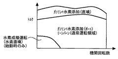
図2は、本発明の実施の形態1において実行される内燃機関10の運転手法を説明するための図である。本実施形態のシステムは、内燃機関10の運転状態に応じて、ガソリンと共に水素を燃料として供給する噴射弁として、水素燃料ポート噴射弁28および水素燃料筒内噴射弁30の何れか一方を選択することを特徴としている。図2に示すように、主として用いられる通常運転領域では、燃料噴射を実行するための噴射弁として、ガソリン噴射弁26と水素燃料ポート噴射弁28とを選択することとしている。より具体的には、これらの噴射弁を用いて、希薄燃焼運転を実行することとしている。
FIG. 2 is a diagram for explaining an operation method of the
水素を燃料として用いると、燃焼速度がガソリンの場合に比して格段に速くなる。このため、通常運転領域では、ガソリンとともに水素を供給することにより燃焼状態を改善させることができ、安定して希薄燃焼運転を実現できる空気過剰率の限界を大幅に高めることができる。また、この運転領域において、水素燃料ポート噴射弁28をガソリン噴射弁26と共に使用し、水素を筒内ではなく吸気ポート18内に噴射することにより、吸気ポート18内に噴射された水素とガソリンとの混合状態、および、それらと空気との混合状態を良くすることができる。このため、本実施形態のシステムによれば、水素燃料筒内噴射弁30により筒内に直接水素を噴射する場合に比して、更に希薄燃焼運転が可能な限界を延ばすことができ、その結果として、更なる燃費性能の向上や排気ガスの清浄化を実現することができる。
When hydrogen is used as a fuel, the combustion speed is much faster than in the case of gasoline. For this reason, in a normal operation area | region, a combustion state can be improved by supplying hydrogen with gasoline, and the limit of the excess air ratio which can implement | achieve a lean combustion operation stably can be raised significantly. Further, in this operation region, the hydrogen fuel
図2に示すように、高負荷領域では、出力優先のため、燃料噴射を実行するための噴射弁として、ガソリン噴射弁26と水素燃料筒内噴射弁30とを選択することとしている。より具体的には、高負荷領域では、ガソリン噴射弁26により、出力空燃比となるように燃料噴射を実行すると共に、水素燃料筒内噴射弁30により、吸気弁22が閉弁した後に水素を筒内に噴射することとしている。このような構成によれば、水素添加により燃焼状態を改善することができるため、トルクを向上させることができる。
As shown in FIG. 2, in the high load region, the
また、高負荷領域において、水素燃料ポート噴射弁28ではなく水素燃料筒内噴射弁30を使用していることにより、上記の如く、吸気弁22が閉弁した後に水素を筒内に供給することができる。水素はガス燃料であるため、吸気弁22の閉弁前に吸気ポート18内に、あるいは筒内に水素を噴射することとすると、供給された水素の分だけ吸入空気量が減少し、その結果、ガソリンのみによる燃料噴射の場合に比して、逆にトルクが減少してしまう。これに対し、本実施形態のシステムによれば、筒内に吸入される吸入空気量を減少させることがないため、水素添加による燃焼改善効果が得られることでトルクを向上させることが可能となる。
Further, by using the hydrogen fuel in-
また、図2に示すように、始動時(ここでいう始動時には、始動直後および暖機が完了するまでの冷機時を含む)では、燃料噴射を実行するための噴射弁として、水素燃料筒内噴射弁30のみを選択することとしている。より具体的には、始動時では、水素燃料筒内噴射弁30により、成層運転を実行することとしている。この成層運転は、点火時に、点火プラグ周辺に着火性に優れた混合気層が形成されるように、圧縮行程時に燃料を噴射する運転である。このような成層運転を実行することとすれば、筒内に供給された燃料全体として見た場合に、吸気ポート18内に、あるいは、筒内に均一に燃料を噴射する場合に比して、より高い空気過剰率で燃焼を実現することができる。
Further, as shown in FIG. 2, at the time of start-up (including the time of start-up here and immediately after start-up and the time of cool-down until completion of warm-up), the hydrogen fuel cylinder is used as an injection valve for executing fuel injection. Only the
本実施形態では、水素燃料ポート噴射弁28ではなく水素燃料筒内噴射弁30を使用していることにより、上述した成層運転を行うことが可能となる。水素は着火性が良いため、水素を燃料として成層運転することにより、ガソリンを燃料とする場合に比して大幅に高い空気過剰率で希薄燃焼運転を実現することができる。このため、更に付け加えると、ガソリンの場合と異なり、NOX排出量が増加してしまうという問題もない。また、始動時には、必要最小限のトルクしか内燃機関10に要求されないため、水素のみによる燃焼によれば十分である。更に、本実施形態の手法によれば、ガソリンを燃料とする場合のように、始動時に着火性の向上のために燃料を増量する必要もなく、また、未燃炭化水素(HC)が排出されることもない。このため、本実施形態のシステムによれば、始動時において、水素を燃料とする成層運転により、内燃機関10を高効率に運転することができる。
In the present embodiment, the stratified operation described above can be performed by using the hydrogen fuel in-
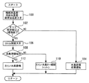
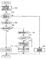
図3は、本実施の形態1において、上記の機能を実現するためにECU50が実行するルーチンのフローチャートである。図3に示すルーチンでは、先ず、触媒床温度、エンジン冷却水温度、エンジン潤滑油温度が取得される(ステップ100)。次いで、上記ステップ100において入手した各温度が全て既定値以上か否かが判定される(ステップ102)。具体的には、内燃機関10が始動した後に暖機が終了しているか否かを判定している。
FIG. 3 is a flowchart of a routine executed by the
上記ステップ102において、暖機が終了していないと判定された場合には、水素燃料筒内噴射弁30による成層運転が実行される(ステップ104)。
一方、上記ステップ102において、暖機が終了していると判定された場合には、スロットル開度が取得される(ステップ106)。次いで、スロットル開度に基づいて、高負荷域か否かが判定される(ステップ108)。
If it is determined in
On the other hand, if it is determined in
その結果、上記ステップ108において、高負荷領域でない、すなわち、通常運転領域であると判定された場合には、ガソリン噴射弁26と水素燃料ポート噴射弁28とによる希薄燃焼運転が実行される(ステップ110)。
一方、上記ステップ108において、高負荷領域であると判定された場合には、ガソリン噴射弁26と水素燃料筒内噴射弁30とにより、ガソリンを出力空燃比となるように噴射し、かつ、筒内に水素を添加する出力優先の運転が実行される(ステップ112)。
As a result, when it is determined in
On the other hand, if it is determined in
以上説明した図3に示すルーチンの処理によれば、内燃機関10の運転状態に応じた最適な噴射弁を選択して水素を供給することができ、その結果として、全ての運転領域において、水素を利用するメリットが最大限得られるような運転を実行することができる。このため、本実施形態のシステムによれば、それぞれの運転状態において、燃費性能の向上、排気ガスの清浄化、および出力性能の向上など、機関の各性能を向上させることができる。
According to the processing of the routine shown in FIG. 3 described above, hydrogen can be supplied by selecting an optimal injection valve in accordance with the operating state of the
尚、上述した実施の形態1においては、ガソリン噴射弁26が、前記第1の発明における「主燃料噴射弁」に相当している。また、ECU50が、上記ステップ102、108の処理を実行することにより前記第1の発明における「噴射弁選択手段」が、上記ステップ104、110、112の処理を実行することにより前記第1の発明における「燃料噴射実行手段」が、それぞれ実現されている。
In the first embodiment described above, the
実施の形態2.
次に、図4を参照して、本発明の実施の形態2について説明する。
本実施形態のシステムは、上述した実施の形態1の装置構成を用いて、ECU50に図4に示すルーチンを実行させることにより実現されるものである。
Embodiment 2. FIG.
Next, a second embodiment of the present invention will be described with reference to FIG.
The system of the present embodiment is realized by causing the
上述した実施の形態1では、高負荷領域であれば、出力優先のため、ガソリンと共に水素を供給することとしている。これに対して、本実施形態のシステムは、高負荷領域であれば常に水素を添加するのではなく、必要に応じて水素を添加することとしている点に特徴を有している。 In Embodiment 1 described above, hydrogen is supplied together with gasoline in order to prioritize output in the high load region. In contrast, the system of the present embodiment is characterized in that hydrogen is not always added in a high load region, but hydrogen is added as necessary.
より具体的には、本実施形態のシステムでは、高負荷領域においては、ガソリン噴射弁26により、出力空燃比となるように燃料噴射を実行することとしている。このような運転がなされると、特に低回転域では、ノッキングが生ずることがある。そこで、本実施形態のシステムでは、ノッキングが発生した場合に、ガソリン噴射に加え、水素燃料筒内噴射弁30から水素を筒内に噴射することとしている。上記の如く、水素を添加すると、燃焼速度が速くなる。このため、ノッキング発生時に水素を添加することにより、ガソリンを増量したり、点火時期をリタードしたりする必要なく、ノッキングを解消することができる。また、水素燃料筒内噴射弁30を用いたことで、吸気弁22の閉弁された後に筒内に水素を噴射することができる。このため、筒内に吸入される新気の量を減少させることなく、つまり、トルクを減少させることなく、ノッキングを解消することができる。
More specifically, in the system of this embodiment, in the high load region, fuel injection is executed by the
また、高負荷領域において、ガソリンを燃料として出力空燃比で運転されると、特に高回転時では、排気温度が通常運転時に比してかなり高くなる。排気温度が高くなりすぎると、排気通路に配置される触媒の劣化が懸念される。そこで、本実施形態のシステムでは、排気温度が所定の上限値を上回った場合に、ガソリン噴射に加え、水素燃料筒内噴射弁30から水素を筒内に噴射することとしている。水素添加により燃焼速度が速くなると、燃焼がより早く完了する。その結果、燃料の熱エネルギがより多く仕事に変換されることで、排気弁24が開弁する際の排気ガスの温度が低下する。このため、排気温度が上限値を上回った場合に水素を添加することにより、排気温度を低下させることができ、その結果、燃焼を改善させることができると共に、触媒を保護することができる。また、この場合にも、水素燃料筒内噴射弁30を用いて、吸気弁22の閉弁された後に筒内に水素を噴射することにより、筒内に吸入される新気の量を減少させることがなく、つまり、トルクを減少させることがない。
Further, when the engine is operated at an output air-fuel ratio using gasoline as fuel in a high load region, the exhaust temperature becomes considerably higher than that during normal operation, particularly at a high speed. If the exhaust temperature becomes too high, there is a concern about the deterioration of the catalyst disposed in the exhaust passage. Therefore, in the system of the present embodiment, when the exhaust gas temperature exceeds a predetermined upper limit value, hydrogen is injected into the cylinder from the hydrogen fuel in-
図4は、本実施の形態2において、内燃機関10の運転状態に応じた適切な噴射弁を選択して燃料噴射を実行するために、図1に示すECU50が実行するルーチンのフローチャートである。尚、図4において、実施の形態1における図3に示すステップと同一のステップについては、同一の符号を付してその説明を省略または簡略する。
FIG. 4 is a flowchart of a routine executed by the
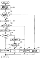
図4に示すルーチンでは、高負荷領域であると判定された場合には(ステップ108)、次いで、KCSセンサの出力が取得され(ステップ114)、そのセンサの情報に基づいて、ノッキングが発生しているか否かが判定される(ステップ116)。
その結果、上記ステップ116において、ノッキングの発生が判定された場合には、ガソリン噴射弁26と水素燃料筒内噴射弁30とが噴射弁として選択される(ステップ112)。
In the routine shown in FIG. 4, when it is determined that the vehicle is in the high load region (step 108), the output of the KCS sensor is acquired (step 114), and knocking occurs based on the sensor information. It is determined whether or not (step 116).
As a result, when it is determined in
一方、上記ステップ116において、ノッキングが発生していないと判定された場合には、次に、排気温度が取得され(ステップ118)、取得された排気温度が上限値を越えているか否かが判定される(ステップ120)。
On the other hand, if it is determined in
その結果、上記ステップ120において、排気温度が上限値を越えていると判定された場合には、ガソリン噴射弁26と水素燃料筒内噴射弁30とが噴射弁として選択される(ステップ112)。
一方、上記ステップ120において、排気温度が上限値を越えていないと判定された場合には、ガソリン噴射弁26のみが噴射弁として選択される(ステップ122)。
As a result, when it is determined in
On the other hand, if it is determined in
以上説明した図4に示すルーチンの処理によれば、高負荷領域において、ノッキングの発生や排気温度の上限値越えが確認された場合に、水素を添加することにより、ノッキング解消や排気温度低下による触媒保護を実現することができ、高負荷領域の上記以外の場合には、ガソリンのみを燃料とする運転を行うことができる。このため、本実施形態のシステムによれば、実施の形態のシステムに比して水素使用総量を減らしつつ、ガソリンと共に、あるいは、ガソリンに代えて水素を燃料とするメリットを享受することができる。 According to the processing of the routine shown in FIG. 4 described above, in the high load region, when occurrence of knocking or exceeding the upper limit of the exhaust temperature is confirmed, by adding hydrogen, knocking is eliminated or the exhaust temperature decreases. Catalyst protection can be realized, and in cases other than the above in the high load region, operation using only gasoline as fuel can be performed. For this reason, according to the system of the present embodiment, it is possible to enjoy the advantage of using hydrogen as fuel together with gasoline or in place of gasoline, while reducing the total amount of hydrogen used as compared with the system of the embodiment.
実施の形態3.
次に、図5を参照して、本発明の実施の形態3について説明する。
本実施形態のシステムは、上述した実施の形態1の装置構成を用いて、ECU50に示すルーチンを実行させることにより実現されるものである。
Embodiment 3 FIG.
Next, a third embodiment of the present invention will be described with reference to FIG.
The system of the present embodiment is realized by causing the routine shown in the
本実施形態のシステムは、通常運転領域において加速が行われる場合に、その加速の開始初期に、水素燃料ポート噴射弁28に代えて水素燃料筒内噴射弁30を選択することとしたという点を除き、実施の形態1の処理と同様である。
The system of the present embodiment is that when acceleration is performed in the normal operation region, the hydrogen fuel in-
加速時に水素を添加する場合には、ガソリンの噴射量が増量されるのに合わせて水素の添加量も増量させることが好ましい。しかしながら、気体燃料である水素は、液体燃料であるガソリンに比して体積が大きい。このため、同時期に吸気ポート18内に噴射量が増量された場合には、水素燃料ポート噴射弁28の追従性は、ガソリン噴射弁26のそれに比して良くない。その一方で、水素燃料筒内噴射弁30は、水素燃料ポート噴射弁28に比して噴射圧力が高い。このため、水素燃料筒内噴射弁30によれば、水素燃料ポート噴射弁を使用する場合に比して、水素増量時に高い追従性を得ることができる。そこで、本実施形態のシステムでは、通常運転領域において、加速が開始された時点から、所定の噴射弁変更期間が経過するまでの間は、つまり、水素燃料ポート噴射弁28によっても増量に追従できるようになるまでの間は、水素燃料ポート噴射弁28から水素燃料筒内噴射弁30に切り替えることとした。
When hydrogen is added at the time of acceleration, it is preferable to increase the hydrogen addition amount as the gasoline injection amount is increased. However, hydrogen, which is a gaseous fuel, has a larger volume than gasoline, which is a liquid fuel. For this reason, when the injection amount is increased in the
図5は、本実施の形態3において、内燃機関10の運転状態に応じて適切な噴射弁を選択して燃料噴射を実行するために、図1に示すECU50が実行するルーチンのフローチャートである。尚、図5において、実施の形態1における図3に示すステップと同一のステップについては、同一の符号を付してその説明を省略または簡略する。
FIG. 5 is a flowchart of a routine executed by the
図5に示すルーチンでは、高負荷領域でないと判定された場合には(ステップ108)、次いで、機関回転数が取得され(ステップ124)、機関回転数とスロットル開度に基づいて、加速条件が成立するか否かが判定される(ステップ126)。
その結果、上記ステップ126において、加速条件が成立しないと判定された場合には、ガソリン噴射弁26と水素燃料ポート噴射弁28とが噴射弁として選択される(ステップ110)。
In the routine shown in FIG. 5, when it is determined that the vehicle is not in the high load region (step 108), the engine speed is acquired (step 124), and the acceleration condition is determined based on the engine speed and the throttle opening. It is determined whether or not it is established (step 126).
As a result, if it is determined in
一方、上記ステップ126において、加速条件の成立が判定された場合には、所定の噴射弁変更期間tが経過するまでの間は、ガソリン噴射弁26と水素燃料ポート噴射弁28とによる燃料噴射に代えて、ガソリン噴射弁26と水素燃料筒内噴射弁30とによる燃料噴射が選択される(ステップ128)。
On the other hand, if it is determined in
本ステップ128で用いられる噴射弁変更期間tは、加速の状態に応じて決定されるべき期間である。つまり、スロットル開度の変化量が大きい場合には、燃料が増量される際の追従性が高く要求される。このため、上記変更期間tは、スロットル開度の変化量が大きいほど長く設定されるのが望ましい。また、急激に加速された場合、すなわち、スロットル開度の変化率が大きい場合にも、その追従性が高く要求される。このため、上記変更期間tは、スロットル開度の変化率が大きいほど長く設定されるのが望ましい。ECU50は、上記の要求を満たすように、噴射弁変更期間tを、スロットル開度の変化量とその変化率との関係で定めたマップを記憶している。具体的には、本ステップ128では、そのマップを参照して、噴射弁変更期間tが設定される。
The injection valve change period t used in
上記ステップ128において、所定の噴射弁変更期間tが経過すると、ガソリン噴射弁26と水素燃料ポート噴射弁28とが噴射弁として選択される(ステップ110)。
以上説明した図5に示すルーチンの処理によれば、加速初期時に水素燃料ポート噴射弁28から水素燃料筒内噴射弁30に切り替えることにより、良好なレスポンスで水素を供給することができる。また、以上の処理によれば、加速の状態に関わらずに水素供給時の追従性を確保することができる。
In
According to the processing of the routine shown in FIG. 5 described above, hydrogen can be supplied with good response by switching from the hydrogen fuel
10 内燃機関
18 吸気ポート
22 吸気弁
26 ガソリン噴射弁
28 水素燃料ポート噴射弁
30 水素燃料筒内噴射弁
36 ポンプ
44 1次レギュレータ
46 2次レギュレータ
50 ECU(Electronic Control Unit)
DESCRIPTION OF
Claims (7)
水素燃料を吸気ポートに噴射する水素燃料ポート噴射弁と、
水素燃料を筒内に噴射する水素燃料筒内噴射弁とを備え、
内燃機関の運転状態に応じて、前記主燃料噴射弁、前記水素燃料ポート噴射弁、および前記水素燃料筒内噴射弁の中から燃料噴射に用いる噴射弁を選択する噴射弁選択手段と、
前記噴射弁選択手段により選択された噴射弁を用いて燃料噴射を実行する燃料噴射実行手段と、
を備えることを特徴とする内燃機関の制御装置。 A main fuel injection valve for injecting main fuel;
A hydrogen fuel port injection valve for injecting hydrogen fuel into the intake port;
A hydrogen fuel in-cylinder injection valve for injecting hydrogen fuel into the cylinder;
An injection valve selection means for selecting an injection valve to be used for fuel injection from the main fuel injection valve, the hydrogen fuel port injection valve, and the hydrogen fuel in-cylinder injection valve according to the operating state of the internal combustion engine;
Fuel injection execution means for executing fuel injection using the injection valve selected by the injection valve selection means;
A control device for an internal combustion engine, comprising:
前記燃料噴射実行手段は、成層運転が実現されるように燃料噴射を実行することを特徴とする請求項1記載の内燃機関の制御装置。 The injection valve selection means, when starting the internal combustion engine, selects fuel injection only by the hydrogen fuel cylinder injection valve,
2. The control apparatus for an internal combustion engine according to claim 1, wherein the fuel injection execution means executes fuel injection so that stratified operation is realized.
前記噴射弁選択手段は、内燃機関の通常運転時には、前記主燃料噴射弁と前記水素燃料ポート噴射弁とによる燃料噴射を選択することを特徴とする請求項1記載の内燃機関の制御装置。 The main fuel injection valve is an injection valve that injects main fuel into the intake port;
2. The control apparatus for an internal combustion engine according to claim 1, wherein the injection valve selection means selects fuel injection by the main fuel injection valve and the hydrogen fuel port injection valve during normal operation of the internal combustion engine.
前記燃料噴射実行手段は、吸気弁が閉弁した後に、前記水素燃料筒内噴射弁からの燃料噴射を開始することを特徴とする請求項1記載の内燃機関の制御装置。 The injection valve selection means selects fuel injection by the main fuel injection valve and the hydrogen fuel in-cylinder injection valve at the time of high load of the internal combustion engine,
2. The control apparatus for an internal combustion engine according to claim 1, wherein the fuel injection execution unit starts fuel injection from the hydrogen fuel in-cylinder injection valve after the intake valve is closed.
前記燃料噴射実行手段は、吸気弁が閉弁した後に、前記水素燃料筒内噴射弁からの燃料噴射を開始することを特徴とする請求項1記載の内燃機関の制御装置。 The injection valve selection means selects fuel injection by the main fuel injection valve and the hydrogen fuel in-cylinder injection valve when knocking is detected,
2. The control apparatus for an internal combustion engine according to claim 1, wherein the fuel injection execution unit starts fuel injection from the hydrogen fuel in-cylinder injection valve after the intake valve is closed.
前記燃料噴射実行手段は、吸気弁が閉弁した後に、前記水素燃料筒内噴射弁からの燃料噴射を開始することを特徴とする請求項1記載の内燃機関の制御装置。 The injection valve selection means selects fuel injection by the main fuel injection valve and the hydrogen fuel in-cylinder injection valve when the exhaust gas temperature exceeds a predetermined upper limit value,
2. The control apparatus for an internal combustion engine according to claim 1, wherein the fuel injection execution unit starts fuel injection from the hydrogen fuel in-cylinder injection valve after the intake valve is closed.
Priority Applications (1)
| Application Number | Priority Date | Filing Date | Title |
|---|---|---|---|
| JP2004117646A JP2005299525A (en) | 2004-04-13 | 2004-04-13 | Control device for internal combustion engine |
Applications Claiming Priority (1)
| Application Number | Priority Date | Filing Date | Title |
|---|---|---|---|
| JP2004117646A JP2005299525A (en) | 2004-04-13 | 2004-04-13 | Control device for internal combustion engine |
Publications (1)
| Publication Number | Publication Date |
|---|---|
| JP2005299525A true JP2005299525A (en) | 2005-10-27 |
Family
ID=35331375
Family Applications (1)
| Application Number | Title | Priority Date | Filing Date |
|---|---|---|---|
| JP2004117646A Withdrawn JP2005299525A (en) | 2004-04-13 | 2004-04-13 | Control device for internal combustion engine |
Country Status (1)
| Country | Link |
|---|---|
| JP (1) | JP2005299525A (en) |
Cited By (9)
| Publication number | Priority date | Publication date | Assignee | Title |
|---|---|---|---|---|
| JP2007182855A (en) * | 2006-01-10 | 2007-07-19 | Toyota Motor Corp | Control device for internal combustion engine |
| JP2007192204A (en) * | 2006-01-23 | 2007-08-02 | Nissan Motor Co Ltd | Sub-chamber internal combustion engine |
| JP2007211608A (en) * | 2006-02-07 | 2007-08-23 | Mazda Motor Corp | Control device for hydrogen engine |
| JP2007303403A (en) * | 2006-05-12 | 2007-11-22 | Mazda Motor Corp | Engine fuel injector |
| DE102007021477A1 (en) * | 2007-05-08 | 2008-11-20 | Daimler Ag | Internal combustion engine and method for operating an internal combustion engine |
| WO2012028941A1 (en) * | 2010-09-03 | 2012-03-08 | Toyota Jidosha Kabushiki Kaisha | Internal combustion engine |
| JP2017020467A (en) * | 2015-07-14 | 2017-01-26 | マツダ株式会社 | Gas fuel engine control device |
| KR102256138B1 (en) * | 2020-06-30 | 2021-05-25 | 주식회사 코니테크놀로지 | Bifuel supply system having a mpi injector and gdi injector for liguidfuel |
| WO2024106061A1 (en) * | 2022-11-15 | 2024-05-23 | 株式会社日立製作所 | Control device for engine electricity generation system |
-
2004
- 2004-04-13 JP JP2004117646A patent/JP2005299525A/en not_active Withdrawn
Cited By (14)
| Publication number | Priority date | Publication date | Assignee | Title |
|---|---|---|---|---|
| JP2007182855A (en) * | 2006-01-10 | 2007-07-19 | Toyota Motor Corp | Control device for internal combustion engine |
| JP2007192204A (en) * | 2006-01-23 | 2007-08-02 | Nissan Motor Co Ltd | Sub-chamber internal combustion engine |
| JP2007211608A (en) * | 2006-02-07 | 2007-08-23 | Mazda Motor Corp | Control device for hydrogen engine |
| JP2007303403A (en) * | 2006-05-12 | 2007-11-22 | Mazda Motor Corp | Engine fuel injector |
| DE102007021477A1 (en) * | 2007-05-08 | 2008-11-20 | Daimler Ag | Internal combustion engine and method for operating an internal combustion engine |
| EP1990523A3 (en) * | 2007-05-08 | 2013-10-30 | Daimler AG | Combustion engine and method for operating a combustion engine |
| JP2012057470A (en) * | 2010-09-03 | 2012-03-22 | Toyota Motor Corp | Internal combustion engine |
| CN103080509A (en) * | 2010-09-03 | 2013-05-01 | 丰田自动车株式会社 | Internal combustion engine |
| WO2012028941A1 (en) * | 2010-09-03 | 2012-03-08 | Toyota Jidosha Kabushiki Kaisha | Internal combustion engine |
| JP2017020467A (en) * | 2015-07-14 | 2017-01-26 | マツダ株式会社 | Gas fuel engine control device |
| KR102256138B1 (en) * | 2020-06-30 | 2021-05-25 | 주식회사 코니테크놀로지 | Bifuel supply system having a mpi injector and gdi injector for liguidfuel |
| WO2024106061A1 (en) * | 2022-11-15 | 2024-05-23 | 株式会社日立製作所 | Control device for engine electricity generation system |
| JP2024071940A (en) * | 2022-11-15 | 2024-05-27 | 株式会社日立製作所 | Engine power generation system control device |
| JP7791805B2 (en) | 2022-11-15 | 2025-12-24 | 株式会社日立製作所 | Engine power generation system control device |
Similar Documents
| Publication | Publication Date | Title |
|---|---|---|
| EP2264303B1 (en) | Control method and device of engine and corresponding engine | |
| WO2002084088A1 (en) | Multiple cylinder internal combustion engine | |
| JP2005299525A (en) | Control device for internal combustion engine | |
| US20160348606A1 (en) | Control apparatus for internal combustion engine | |
| JP2010053716A (en) | Control device of internal combustion engine | |
| JP4784431B2 (en) | Control device for gas fuel internal combustion engine | |
| JP4365812B2 (en) | Control device and control method for internal combustion engine | |
| JP2007247522A (en) | Fuel injection control device for internal combustion engine | |
| JP4277883B2 (en) | In-cylinder injection spark ignition internal combustion engine | |
| JP2006002683A (en) | Control device for internal combustion engine | |
| JP2009047094A (en) | Control unit for gasoline engine | |
| JP4102268B2 (en) | Compression ignition internal combustion engine | |
| JP2011017285A (en) | Fuel injection control device for internal combustion engine | |
| JP4602383B2 (en) | Control device for variable valve internal combustion engine | |
| JP4677996B2 (en) | Internal combustion engine using hydrogen | |
| JP2007211608A (en) | Control device for hydrogen engine | |
| JP2005098132A (en) | Combustion control system for compression ignition internal combustion engine | |
| JP4406881B2 (en) | Engine control device | |
| JP2006132399A (en) | Control device and control method for supercharged engine | |
| JP5435157B2 (en) | Fuel injection control device for internal combustion engine | |
| JP4304463B2 (en) | Fuel injection control device for internal combustion engine | |
| JP2005163609A (en) | INTERNAL COMBUSTION ENGINE OPERATION CONTROL DEVICE AND INTERNAL COMBUSTION ENGINE OPERATION CONTROL METHOD | |
| JP2010203333A (en) | Control device for multi-cylinder internal combustion engine | |
| JP2003090249A (en) | Spark ignition direct injection internal combustion engine | |
| JP4123093B2 (en) | Fuel injection control device for internal combustion engine |
Legal Events
| Date | Code | Title | Description |
|---|---|---|---|
| A300 | Application deemed to be withdrawn because no request for examination was validly filed |
Free format text: JAPANESE INTERMEDIATE CODE: A300 Effective date: 20070703 |