JP4602383B2 - Control device for variable valve internal combustion engine - Google Patents
Control device for variable valve internal combustion engine Download PDFInfo
- Publication number
- JP4602383B2 JP4602383B2 JP2007210956A JP2007210956A JP4602383B2 JP 4602383 B2 JP4602383 B2 JP 4602383B2 JP 2007210956 A JP2007210956 A JP 2007210956A JP 2007210956 A JP2007210956 A JP 2007210956A JP 4602383 B2 JP4602383 B2 JP 4602383B2
- Authority
- JP
- Japan
- Prior art keywords
- intake
- valve
- amount
- intake valve
- air amount
- Prior art date
- Legal status (The legal status is an assumption and is not a legal conclusion. Google has not performed a legal analysis and makes no representation as to the accuracy of the status listed.)
- Expired - Fee Related
Links
Images


Classifications
-
- Y02T10/146—
-
- Y02T10/18—
Description
本発明は、自動車等の車両で使用される可変動弁式内燃機関及び制御方法に関し、特に、吸気バルブのリフト量、開弁期間を連続的に制御することにより吸入空気量制御を行う可変動弁式内燃機関及び制御方法に関する。 The present invention relates to a variable valve operating internal combustion engine and a control method used in a vehicle such as an automobile, and more particularly to a variable valve that performs intake air amount control by continuously controlling a lift amount and a valve opening period of an intake valve. The present invention relates to a valve-type internal combustion engine and a control method.
近年、自動車用内燃機関の燃費低減を目的として、リフト量、開弁期間を可変設定できる吸気バルブによって吸入空気量制御を行う可変動弁式内燃機関が普及しつつある。可変動弁式内燃機関として、一つの気筒毎に二つの吸気ポートとその各吸気ポートを個別に開閉する吸気バルブを有し、内燃機関の低回転領域においては、一方の吸気バルブをエンジン負荷の高低にかかわらず閉弁固定し、他方の吸気バルブのリフト量、開弁期間の少なくとも一方をエンジン負荷の増大に対応して連続して徐々に大きくすることにより、吸入空気量制御を行い、同時に燃焼室内のスワール制御を行うものがある(例えば、特許文献1)。 In recent years, for the purpose of reducing the fuel consumption of an internal combustion engine for automobiles, a variable valve-operated internal combustion engine that controls intake air amount by an intake valve that can variably set a lift amount and a valve opening period is becoming widespread. As a variable valve-operated internal combustion engine, each cylinder has two intake ports and intake valves that individually open and close each intake port. In the low speed region of the internal combustion engine, one of the intake valves is connected to the engine load. Regardless of the height, the valve is closed and fixed, and at least one of the lift amount and the valve opening period of the other intake valve is continuously increased gradually in response to an increase in engine load. There exists what performs swirl control in a combustion chamber (for example, patent documents 1).
特許文献1に示されているような従来の可変動弁式内燃機関では、エンジン低回転数運転域で、一部の吸気バルブの休止制御を行うため、低回転高負荷領域において吸入空気量が不足すると考えられる。
In a conventional variable valved internal combustion engine such as that disclosed in
また、従来の可変動弁式内燃機関では、低吸入空気量領域での吸気バルブのリフト量、開弁期間のばらつき(誤差)による吸入空気量のばらつきを低減することの考慮がなされていない。吸入空気量のばらつき、特に、低吸入空気量領域の吸入空気量のばらつきは、混合気(燃料−空気)の空燃比の制御精度を大きく低下し、エンジン性能を悪化する。 Further, in the conventional variable valve-operated internal combustion engine, no consideration is given to reducing variations in intake air amount due to variations (errors) in the lift amount and valve opening period of the intake valve in the low intake air amount region. Variations in the intake air amount, particularly variations in the intake air amount in the low intake air amount region, greatly reduce the control accuracy of the air-fuel ratio of the air-fuel mixture (fuel-air) and deteriorate engine performance.
本発明は、上述の如き問題点を解消するためになされたもので、その目的とするところは、吸気バルブのリフト量や開弁期間を連続的に制御することにより吸入空気量制御を行うことができる可変動弁機構付きの内燃機関において、吸入空気量が不足する虞れがなく、リフト量、開弁期間のばらつきによる吸入空気量のばらつきを低減して高精度な吸入空気量制御を行うことができる可変動弁式内燃機関及び制御方法を提供することにある。 The present invention has been made to solve the above-described problems, and an object thereof is to perform intake air amount control by continuously controlling the lift amount and valve opening period of the intake valve. In an internal combustion engine with a variable valve mechanism that can perform the intake valve, there is no fear that the intake air amount will be insufficient, and highly accurate intake air amount control is performed by reducing variations in the intake air amount due to variations in lift amount and valve opening period. It is an object of the present invention to provide a variable valve operating internal combustion engine and a control method.
上述の目的を達成するために、本発明による可変動弁式内燃機関は、一つの気筒毎に複数個の吸気ポートとその各吸気ポートを個別に開閉する吸気バルブを有し、吸気バルブのリフト量あるいは開弁期間の少なくとも何れか一方を連続的に可変設定する可変動弁機構を備え、吸気バルブにより吸入空気量の制御を行う可変動弁式内燃機関において、一つの気筒における前記複数個の吸気バルブのリフト量あるいは開弁期間の少なくとも何れか一方が各吸気バルブ毎に各々個別に可変設定可能に構成され、内燃機関の吸入空気量等の運転状態に応じて一つの気筒における前記複数個の吸気バルブの動作モードをそれぞれ独立に設定制御する制御手段を有する。 In order to achieve the above-described object, a variable valve-actuated internal combustion engine according to the present invention has a plurality of intake ports for each cylinder and intake valves that individually open and close the intake ports, and lifts the intake valves. In a variable valved internal combustion engine that includes a variable valve mechanism that continuously and variably sets at least one of an amount and a valve opening period, and that controls the amount of intake air using an intake valve, At least one of the lift amount and the valve opening period of the intake valve can be individually variably set for each intake valve, and the plural in one cylinder according to the operating state such as the intake air amount of the internal combustion engine Control means for independently setting and controlling the operation modes of the intake valves.
この発明による可変動弁式内燃機関によれば、一つの気筒における複数個の吸気バルブの動作モード(リフト量あるいは/および開弁期間)が制御手段によって内燃機関の運転状態に応じてそれぞれ独立に設定され、各吸気バルブ毎の動作モードの適正設定により、吸入空気量不足が生じることがなく、リフト量、開弁期間のばらつきによる吸入空気量のばらつきを低減することが可能になる。 According to the variable valve type internal combustion engine of the present invention, the operation mode (lift amount or / and valve opening period) of a plurality of intake valves in one cylinder is independently controlled by the control means according to the operating state of the internal combustion engine. By setting the appropriate operation mode for each intake valve, there is no shortage of intake air amount, and it is possible to reduce variations in intake air amount due to variations in lift amount and valve opening period.
本発明による可変動弁式内燃機関では、前記制御手段は、低空気量領域においては、一つの気筒に設けられた前記複数個の吸気バルブのうちの少なくとも1つの吸気バルブの休止を行い、中、高空気量領域においては、低空気量領域において作動させた吸気バルブおよびその他の吸気バルブを作動させる。これにより、吸入空気量不足が生じることがなく、リフト量、開弁期間のばらつきによる吸入空気量のばらつきが低減する。 In the variable valve operating internal combustion engine according to the present invention, the control means pauses at least one intake valve of the plurality of intake valves provided in one cylinder in a low air amount region. In the high air amount region, the intake valve and other intake valves operated in the low air amount region are operated. As a result, there is no shortage of intake air amount, and variations in intake air amount due to variations in lift amount and valve opening period are reduced.
本発明による可変動弁式内燃機関は、一つの気筒に設けられた複数個の吸気ポートおよびそれに対応する吸気バルブの径が異なる。この場合、前記制御手段は、低空気量領域では、一つの気筒に設けられた前記複数個の吸気バルブのうち、径の大きい方の吸気バルブを休止させ、中、高空気量領域では、一つの気筒に設けられた前記複数個の吸気バルブの全てを作動させる。これにより、吸入空気量不足が生じることがなく、リフト量、開弁期間のばらつきによる吸入空気量のばらつきが低減する。 In the variable valve operating internal combustion engine according to the present invention, the diameters of a plurality of intake ports provided in one cylinder and the corresponding intake valves are different. In this case, the control means stops the intake valve having the larger diameter among the plurality of intake valves provided in one cylinder in the low air amount region, and reduces the intake valve in the middle and high air amount regions. All of the plurality of intake valves provided in one cylinder are operated. As a result, there is no shortage of intake air amount, and variations in intake air amount due to variations in lift amount and valve opening period are reduced.
また、前記制御手段は、中空気量領域では、一つの気筒に設けられた前記複数個の吸気バルブのうち、径の大きい方の吸気バルブを作動させ、径の小さい方の吸気バルブの休止を行い、高空気量領域では、一つの気筒に設けられた前記複数個の吸気バルブの全てを作動させる。これにより、吸入空気量不足が生じることがなく、リフト量、開弁期間のばらつきによる吸入空気量のばらつきが低減する。 Further, the control means operates the intake valve having a larger diameter among the plurality of intake valves provided in one cylinder in the medium air amount region, and pauses the intake valve having the smaller diameter. In the high air volume region, all of the plurality of intake valves provided in one cylinder are operated. As a result, there is no shortage of intake air amount, and variations in intake air amount due to variations in lift amount and valve opening period are reduced.
また、前記制御手段は、低空気量領域から高空気量領域に移る過渡時には、低空気量領域において作動させる吸気バルブによる吸入空気量を過渡変化中に低下させると共に、中、高空気量領域において作動させる吸気バルブによる吸入空気量を過渡変化中に増加させ、これとは、反対に、高空気量領域から低空気量領域に移る過渡時には、中、高空気量領域において作動させる吸気バルブによる吸入空気量を過渡変化中に低下させると共に、低空気量領域において作動させる吸気バルブによる吸入空気量を過渡変化中に増加させる。これにより、吸入空気量不足が生じることがなく、リフト量、開弁期間のばらつきによる吸入空気量のばらつきが低減する。 In addition, during the transition from the low air amount region to the high air amount region, the control means reduces the intake air amount by the intake valve operated in the low air amount region during the transient change, and in the middle and high air amount regions. The intake air amount by the intake valve to be activated is increased during the transient change, and conversely, during the transition from the high air amount region to the low air amount region, the intake by the intake valve to be operated in the middle and high air amount regions The air amount is decreased during the transient change, and the intake air amount by the intake valve operated in the low air amount region is increased during the transient change. As a result, there is no shortage of intake air amount, and variations in intake air amount due to variations in lift amount and valve opening period are reduced.
また、前記制御手段は、低空気量領域において作動させる吸気バルブから高空気量領域において作動させる吸気バルブに作動させるバルブを切り換える際に、後者の最小吸入空気量が前者の最大吸入空気量以上とする。 Further, when the control means switches the valve to be operated from the intake valve that is operated in the low air amount region to the intake valve that is operated in the high air amount region, the latter minimum intake air amount is greater than or equal to the former maximum intake air amount. To do.
また、前記制御手段は、低空気量領域から中〜高空気量領域に移る過渡変化時において、過渡変化前の運転状態およびドライバが意図する過渡変化後の運転状態に応じて、低空気量領域において作動させる吸気バルブを通過する空気量の低下幅を変化させることもでき、過渡変化前の運転状態およびドライバが意図する過渡運転に適合した過渡特性が得られる。 Further, the control means is configured to change the low air amount region according to the operation state before the transient change and the operation state after the transient change intended by the driver at the time of the transient change from the low air amount region to the medium to high air amount region. It is also possible to change the amount of decrease in the amount of air passing through the intake valve that is operated in step S1, and to obtain a transient characteristic that is suitable for the operation state before the transient change and the transient operation intended by the driver.
また、本発明による可変動弁式内燃機関は、過渡変化前の運転状態およびドライバが意図する過渡変化後の運転状態に応じて、低負荷運転領域において作動させる吸気バルブを通過する空気量を過渡変化する前に比べて低下させると共に、高負荷運転領域において作動させる吸気バルブを通過する空気量を過渡変化する前に比べて増加させることを禁止する。 Further, the variable valve operating internal combustion engine according to the present invention transiently changes the amount of air passing through the intake valve operated in the low load operation region according to the operating state before the transient change and the operating state after the transient change intended by the driver. It is prohibited to increase the amount of air passing through the intake valve operated in the high-load operation region as compared to before the transient change while reducing the amount compared to before the change.
また、本発明による可変動弁式内燃機関は、低空気量領域では吸気バルブ上流に負圧を発生させる手段を有し、低空気量領域では一つの気筒に設けられた前記複数個の吸気バルブのうち、一つの吸気バルブにより吸入空気量制御を行う。これにより、低空気量領域では吸気バルブのリフト量、開弁期間を拡大でき、リフト量、開弁期間のばらつきによる吸入空気量のばらつきが、より一層低減する。 Further, the variable valve operating internal combustion engine according to the present invention has means for generating a negative pressure upstream of the intake valve in the low air amount region, and the plurality of intake valves provided in one cylinder in the low air amount region. Of these, the intake air amount is controlled by one intake valve. Thereby, the lift amount and valve opening period of the intake valve can be expanded in the low air amount region, and the variation in the intake air amount due to the variation in the lift amount and the valve opening period is further reduced.
また、本発明による可変動弁式内燃機関は、一つの気筒に配設された前記複数個の吸気ポートの各々に個別に燃料噴射を行う燃料噴射弁を有し、前記複数個の吸気ポートへのそれぞれの燃料噴射量が一つの気筒に設けられた吸気バルブを通過するそれぞれの空気量により決定される。これにより、複数個の吸気ポートにおける混合気の生成が不均一になることがない。 In addition, the variable valve operating internal combustion engine according to the present invention includes a fuel injection valve that individually injects fuel into each of the plurality of intake ports arranged in one cylinder. The respective fuel injection amounts are determined by the respective air amounts that pass through the intake valves provided in one cylinder. Thereby, the generation of the air-fuel mixture in the plurality of intake ports does not become uneven.
また、上述の目的を達成するために、本発明による可変動弁式内燃機関の制御方法は、一つの気筒毎に複数個の吸気ポートとその各吸気ポートを個別に開閉する吸気バルブを有し、吸気バルブのリフト量あるいは開弁期間の少なくとも何れか一方を連続的に可変設定する可変動弁機構を備え、吸気バルブにより吸入空気量の制御を行う可変動弁式内燃機関の制御方法において、一つの気筒における前記複数個の吸気バルブのリフト量あるいは開弁期間の少なくとも何れか一方を、内燃機関の運転状態に応じてそれぞれ個別に制御する。 In order to achieve the above object, a control method for a variable valve operating internal combustion engine according to the present invention includes a plurality of intake ports for each cylinder and intake valves that individually open and close each intake port. In the control method of the variable valve operating internal combustion engine, which includes a variable valve mechanism that continuously and variably sets at least one of the lift amount or the valve opening period of the intake valve and controls the intake air amount by the intake valve, At least one of lift amounts or valve opening periods of the plurality of intake valves in one cylinder is individually controlled according to the operating state of the internal combustion engine.
この発明による可変動弁式内燃機関の制御方法によれば、一つの気筒における複数個の吸気バルブの動作モード(リフト量あるいは/および開弁期間)が制御手段によって内燃機関の運転状態に応じてそれぞれ独立に設定され、各吸気バルブ毎の動作モードの適正設定により、吸入空気量不足が生じることがなく、リフト量、開弁期間のばらつきによる吸入空気量のばらつきを低減することが可能になる。 According to the control method for a variable valve internal combustion engine according to the present invention, the operation mode (lift amount or / and valve opening period) of a plurality of intake valves in one cylinder is determined by the control means in accordance with the operating state of the internal combustion engine. Each is set independently, and the appropriate setting of the operation mode for each intake valve prevents the intake air amount from becoming insufficient, and it is possible to reduce variations in intake air amount due to variations in lift amount and valve opening period. .
以上の説明から理解される如く、この発明による可変動弁式内燃機関及び制御方法によれば、一つの気筒に設けられた複数個の吸気バルブの動作モードをエンジンの運転領域により個々に変更することにより、吸気バルブのリフト量および開弁期間のばらつきによる吸入空気量のばらつきを低減することができ、吸入空気量のばらつきに起因する混合気の空燃比の制御精度の低下を解消し、エンジン性能の向上を図ることができる。 As understood from the above description, according to the variable valve operating internal combustion engine and the control method according to the present invention, the operation modes of a plurality of intake valves provided in one cylinder are individually changed depending on the operation region of the engine. As a result, it is possible to reduce the variation in intake air amount due to variations in the lift amount and valve opening period of the intake valve, eliminate the deterioration in the control accuracy of the air-fuel ratio of the air-fuel mixture caused by the variation in intake air amount, and The performance can be improved.
以下に添付の図を参照してこの発明の実施の形態を詳細に説明する。
(実施形態1)
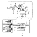
図1は本発明による可変動弁式内燃機関の実施形態1を示している。可変動弁式内燃機関100は、自動車用ガソリンエンジンであり、シリンダブロック1に形成されたシリンダホア3内にピストン4を往復動可能に有する。ピストン4はコネクティングロッド2によって図示しないクランク機構に連結されている。シリンダブロック1の上部にはシリンダヘッド5が取り付けられている。シリンダヘッド5はピストン4との間に燃焼室6を画定している。なお、図1では、一つの気筒(燃焼室6)のみを示しているが、通常、自動車用ガソリンエンジンは、4気筒、6気筒等の多気筒エンジンである。
Embodiments of the present invention will be described below in detail with reference to the accompanying drawings.
(Embodiment 1)
FIG. 1 shows
シリンダヘッド5には、吸気ポート11、排気ポート21が形成されている。また、シリンダヘッド5には、火花点火用の点火プラグ9が取り付けられていると共に、吸気ポート11を開閉する吸気バルブ7、排気ポート21を開閉する排気バルブ8が各々取り付けられている。吸気ポート11、排気ポート21、吸気ポート11を開閉する吸気バルブ7、排気ポート21を開閉する排気バルブ8は、各気筒毎に2個設けられている(図2参照)。
An
吸気バルブ7には、リフト量、開弁期間および位相を連続的に変更可能とする可変動弁機構10が設けられている。吸気バルブ7の上流側には吸気ポート11へ燃料を噴射する燃料噴射弁12が取り付けられている。
The
内燃機関100は、ピストン4の往復動作(吸気行程)によって負圧となる燃焼室6に吸気ポート11より空気を吸入する。燃料噴射弁12より吸気ポート11に噴射された燃料は、燃焼室6に吸入される吸入空気と共に燃焼室6に吸入される。
The
燃焼室6内に吸入された燃料は、燃焼室6内に吸入された空気と混合し、点火プラグ9により点火され、燃焼する。燃焼室6の既燃焼ガス、すなわち排気ガスはピストン4の往復動作(排気行程)によって排気ポート21から燃焼室6外に排出される。
The fuel sucked into the
コントロールユニット13は、コンピュータ式のものであり、エンジン制御部16、可変動弁制御部17、インジェクタ駆動回路18および変速機制御部19などを含み、各種のセンサの出力信号から内燃機関100の運転状態を検出し、その検出結果に応じて内燃機関100に装着されている可変動弁機構10、燃料噴射弁12、点火プラグ9を制御する。
The
コントロールユニット13に各種センサからの入力される信号を以下に示す。本実施形態では、クランク角、気筒判別信号、スロットル開度、アクセルペダル踏量、ブレーキペダル踏量、吸気温度、吸入空気量、水温、排気温度、排気酸素濃度が、コントロールユニット13に入力される。図中には、吸入空気量センサ14、スロットル開度センサ15のみを示してある。
Signals input from the various sensors to the
各気筒に対する燃料噴射および点火時期はコントロールユニット13により制御され、噴射パルス信号および点火信号は、コントロールユニット13において演算処理され、噴射および点火時期を制御している。
The fuel injection and ignition timing for each cylinder is controlled by the
本実施形態の内燃機関100では、ポンプ損失低減による燃費向上を目的として、可変動弁機構10を備えた吸気バルブ7を用いることにより、吸入空気量制御を行うことができる。可変動弁機構10を備えた吸気バルブ7を用いて吸入空気量制御を行う際、部分負荷運転領域において、吸気バルブ7のリフト量および開弁期間を連続的に可変することにより、吸入空気量を制御している。ポンプ損失が最も大きく発生するのは、従来、スロットルが全閉状態となるアイドル運転領域であるため、本実施形態に記載の可変動弁機構を用いることにより、最も燃費低減効果が得られるのはアイドル運転領域である。
In the
しかし、可変動弁機構でアイドル運転を行うためには吸気バルブのリフト量および開弁期間が極めて小さくする必要が生じるため、吸気バルブのリフト量および開弁期間のばらつきによるサイクル毎の吸入空気量のばらつきおよび気筒間の吸入空気量のばらつきが発生する。 However, in order to perform idle operation with the variable valve mechanism, the lift amount and the valve opening period of the intake valve need to be extremely small. Therefore, the intake air amount per cycle due to variations in the lift amount and the valve opening period of the intake valve Variation and intake air amount variation between cylinders occur.
そこで、本実施形態では、一つの気筒に設けられた2個の吸気バルブそれぞれのバルブシート径を異なるように構成している。図2にシリンダヘッド5をピストン4側から見たものを示す。本実施形態では、吸気ポート11aのバルブシート径の小さい吸気バルブ7aと、吸気ポート11bのバルブシート径の大きい吸気バルブ7bを有する構成としている。
Therefore, in the present embodiment, the valve seat diameters of the two intake valves provided in one cylinder are configured to be different. FIG. 2 shows the
さらには、可変動弁機構10は、一つの気筒における吸気バルブ7a、7bのリフト量、開弁期間を各々個別に可変設定可能に構成されている。この可変動弁機構10の制御手段であるコントロールユニット13の可変動弁制御部17は、内燃機関100の運転状態に応じて一つの気筒における吸気バルブ7a、7bの動作モードをそれぞれ独立に設定制御する。ここで云う吸気バルブ7a、7bの動作モードとは、リフト量、開弁期間、位相の組合せを意味する。
Furthermore, the
図3は、本実施形態の可変動弁式内燃機関の吸気バルブ7a、7bの作動モードを示したものである。図3(a)は、トルクとエンジン回転数とにより決まる低〜高空気量領域(A)〜(D)の分布例を示している。本実施形態での空気量(吸入空気量)は、エンジン1サイクル中に吸入される空気量を意味している。
FIG. 3 shows operation modes of the
具体的には、低空気量領域(A)では、図3(b)に示すように、吸気バルブ7bをゼロリフトとし、吸気バルブ7aのリフト量、開弁期間および位相を可変設定することにより空気量制御を行う。中空気量領域(B)では、図3(c)に示すように、吸気バルブ7aをゼロリフトとし、吸気バルブ7bのリフト量、開弁期間および位相を可変設定することにより空気量制御を行う。高空気量領域(C)、(D)では、図3(d)、(e)に示すように、吸気バルブ7aおよび吸気バルブ7bの両方のリフト量、開弁期間および位相を可変設定することにより吸入空気量制御を行う。
Specifically, in the low air amount region (A), as shown in FIG. 3B, the
高空気量領域における比較的空気量が小さい領域(C)では、吸気バルブ7bのリフト量および開弁期間をフルリフト状態よりも小さくすると共に位相を変化させることで吸入空気量を小さくし、吸気バルブ7aのリフト量および開弁期間を大きくすると共に位相を変化させ、要求空気量と吸気バルブ7bを通過する空気量の差分が吸気バルブ7aを通過して燃焼室6に供給されるよう制御する。
In the region (C) where the air amount is relatively small in the high air amount region, the intake air amount is reduced by changing the phase and changing the lift amount and the valve opening period of the
図2に示されている実施形態では、吸気バルブが2個としてあるが、吸気バルブが3個であっても構わない。吸気バルブが3個の場合には、バルブシート径の最も小さい吸気バルブを7a、それ以外の2個の吸気バルブを大径の吸気バルブ7bとすればよい。
In the embodiment shown in FIG. 2, there are two intake valves, but there may be three intake valves. When there are three intake valves, the intake valve with the smallest valve seat diameter may be 7a, and the other two intake valves may be the
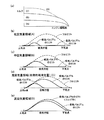
上述したように、本実施形態では、低空気量領域(A)においては、小径の吸気バルブ7aのみで吸入空気量制御を行うので、一つの気筒に設けられた複数個の吸気バルブそれぞれを同様に制御して吸入空気量制御を行った場合に比べ、要求吸入空気量に適合する開口面積を確保するためのリフト量および開弁期間を拡大する必要がある。ここで云う開口面積は、1行程毎の単位時間当たりのポート開口面積である。
As described above, in the present embodiment, in the low air amount region (A), the intake air amount control is performed only by the small-
これにより、図4に示すように、低空気量領域(A)における吸気バルブリフト量および開弁期間のばらつきによる空気量のばらつきを低減することができる。これは、吸気バルブ7aのポート径が小さいので、リフト量、開弁期間のばらつき量に対する吸入空気量のばらつきの比率が小さいことを意味する。なお、図4中のリフトばらつき量は目標リフトからのばらつきを表し、吸入空気量のばらつきは目標空気量からのばらつきを表している。
Thereby, as shown in FIG. 4, the variation in the air amount due to the variation in the intake valve lift amount and the valve opening period in the low air amount region (A) can be reduced. This means that since the port diameter of the
吸気バルブ7aのみで吸入空気量制御を行う低空気量領域(A)では、各エンジン回転数において吸気バルブ7aをフルリフトとした場合の空気量により決定される。なお、低空気量領域(A)では、吸気バルブ上流に設けられたスロットルを閉じることで、吸気管内に負圧を与えて吸気バルブ7aのリフト量および開弁期間を拡大してもよい。これは、吸気管内に充満する空気量が減少するため、吸気バルブ7aの開口面積を拡大して空気量を確保する必要が生じるためである。
In the low air amount region (A) where the intake air amount control is performed only by the
中空気量領域(B)では、吸気バルブ7bのみで空気量制御を行うので、吸気バルブ7aおよび吸気バルブ7bの両バルブを作動させた場合に比べ、要求吸入空気量に適合する吸気バルブ7bの開口面積を確保するためにリフト量および開弁期間を拡大する必要がある。これにより、中空気量領域(B)における吸気バルブ7bのリフト量および開弁期間のばらつきによる吸入空気量のばらつきを低減することができる。
In the middle air amount region (B), since the air amount control is performed only by the
中空気量領域(B)で、吸気バルブ7aと吸気バルブ7bの両方を動作させない理由は、吸気バルブ7aをゼロリフトとすることにより、吸気バルブ7aのリフト量および開弁期間のばらつきによる吸入空気量のばらつきが加算されることを排除するためである。
The reason why both the
吸気バルブ7bのみで吸入空気量制御を行う中空気量領域(B)は、各エンジン回転数において吸気バルブ7bをフルリフトとした場合の空気量により決定される。
The middle air amount region (B) in which the intake air amount control is performed only by the
高空気量領域(C)、(D)では、吸気バルブ7aおよび吸気バルブ7bの両方を作動させ、吸入空気量の確保を図る。高空気量領域において比較的空気量が小さい領域(C)では、吸気バルブ7bのリフト量および開弁期間を最大に保持しながら吸気バルブ7aをゼロリフトからリフト量および開弁期間を拡大した場合、吸気バルブ7aのリフト量および開弁期間のばらつきにより空気量にばらつきが発生する。
In the high air amount regions (C) and (D), both the
そこで、エンジン回転数により吸気バルブ7bを通過する空気量のばらつきが許容範囲内となるリフト量および開弁期間を与えた場合の吸気バルブ7aのリフト量および開弁期間を予め定めておき、高空気量領域において比較的空気量が小さい領域(C)では、吸気バルブ7aに予め定められたリフト量および開弁期間を与え、要求空気量からの吸気バルブ7aを通過する空気量の差分を吸気バルブ7bのリフト量、開弁期間および位相を制御することにより与えることができる。
Therefore, the lift amount and the valve opening period of the
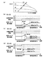
次に、本実施形態での過渡時における制御について図5を用いて説明する。ドライバ意図に応じてコントロールユニット13により図5(a)に示すようにエンジン回転およびトルクの様々な変化が発生する。
Next, the control at the time of transition in this embodiment is demonstrated using FIG. Depending on the driver's intention, the
図5(a)において目標空気量領域(A)から(B)に変化する場合には、図5(b)に示されているように、まず、吸気バルブ7aのリフト量および開弁期間を増加させることにより、開口面積の増加を図る。吸気バルブ7aのリフト量および開弁期間が構成上の最大値に達し、吸気バルブ7aのみを作動させた場合に得られる最大の空気量に達すると、過渡変化中に、吸気バルブ7aのリフト量および開弁期間を減少させると共に、これに同期して吸気バルブ7bのリフト量および開弁期間を増加させて開口面積を増加させる。吸気バルブ7bの開口面積の目標値は、ドライバ意図から決定される目標空気量により決定される。最終的に吸気バルブ7aの開口面積をゼロとする。
In the case of changing from the target air amount region (A) to (B) in FIG. 5 (a), first, as shown in FIG. 5 (b), the lift amount and the valve opening period of the
この制御を行う理由は以下のとおりである。吸気バルブ7aの開口面積を最大値に保持したまま吸気バルブ7bの開口面積を増加させるように制御を行うとすると、吸気バルブ7aのみを作動させた場合に得られる最大の空気量から僅かに大きい空気量が目標である場合、吸気バルブ7bのリフト量および開弁期間を微小に増加させて開口面積を増加させる必要が生じるため、吸気バルブ7bのリフト量および開弁期間のばらつきによる吸入空気量のばらつきが発生する。
The reason for performing this control is as follows. If control is performed to increase the opening area of the
そこで、本実施形態では、吸気バルブ7aの開口面積を減少させることによって、空気量確保のために吸気バルブ7bの開口面積を増加させる必要を生じさせている。この制御により、吸気バルブ7bのリフト量および開弁期間を拡大することが可能となるため、吸気バルブ7bのリフト量および開弁期間のばらつきによる吸入空気量のばらつきを低減することができる。
Therefore, in the present embodiment, by reducing the opening area of the
最終的に吸気バルブ7aの開口面積をゼロとすることにより、吸気バルブ7aのリフト量および開弁期間のばらつきによる吸入空気量のばらつきを完全に排除することができる。なお、吸気バルブ7aの開口面積をゼロとせずとも構わない。その場合には、吸気バルブ7aおよび吸気バルブ7bの開口面積の目標値は、ドライバ意図から決定される目標空気量により決定される。
Finally, by setting the opening area of the
また、低空気量領域から中空気量領域に移る過渡変化時において、過渡変化前の運転状態およびドライバが意図する過渡変化後の運転状態に応じて、低空気量領域において作動させる吸気バルブ7aを通過する空気量の低下幅を変化させることもできる。
Further, at the time of a transient change from the low air amount region to the medium air amount region, the
図5(a)において目標空気量領域(B)から(C)に変化する場合には、図5(c)に示されているように、まず、吸気バルブ7bのリフト量および開弁期間を増加させることにより、開口面積の増加を図る。吸気バルブ7bのリフト量および開弁期間が構成上の最大値に達し、吸気バルブ7bのみを作動させた場合に得られる最大の空気量に達すると、過渡変化中に、吸気バルブ7bのリフト量および開弁期間を減少させると共に、これに同期して吸気バルブ7aのリフト量および開弁期間を増加させて開口面積を増加させる。吸気バルブ7aおよび吸気バルブ7bの開口面積の目標値は、ドライバ意図から決定される目標空気量により決定される。
When changing from the target air amount region (B) to (C) in FIG. 5 (a), first, as shown in FIG. 5 (c), the lift amount and the valve opening period of the
この制御を行う理由は以下のとおりである。吸気バルブ7bの開口面積を最大値に保持したまま吸気バルブ7aの開口面積を増加させるように制御を行うとすると、吸気バルブ7bのみを作動させた場合に得られる最大の空気量から僅かに大きい空気量が目標である場合、吸気バルブ7aのリフト量および開弁期間を微小に増加させて開口面積を増加させる必要が生じるため、吸気バルブ7aのリフト量および開弁期間のばらつきによる吸入空気量のばらつきが発生する。
The reason for performing this control is as follows. If control is performed to increase the opening area of the
そこで、本実施形態では、吸気バルブ7bの開口面積を減少させることによって、空気量確保のために吸気バルブ7aの開口面積を増加させる必要を生じさせている。この制御により、吸気バルブ7aのリフト量および開弁期間を拡大することが可能となるため、吸気バルブ7aのリフト量および開弁期間のばらつきによる吸入空気量のばらつきを低減することができる。これにより、吸入空気量のばらつきに起因する混合気の空燃比の制御精度の低下が解消され、エンジン性能の向上が図られる。
Therefore, in this embodiment, it is necessary to increase the opening area of the
図5(a)において目標空気量領域(C)から(D)に変化する場合には、図5(d)に示されているように、吸気バルブ7aおよび吸気バルブ7bのリフト量および開弁期間を増加させることにより開口面積の増加を図る。目標空気量領域(C)から(D)への過渡時では、吸気バルブ7aおよび吸気バルブ7bのリフト量および開弁期間が過渡中を通じて十分に大きい値を保持できるため、上述した目標空気量領域(A)から(B)、目標空気量領域(B)から(C)の過渡変化時のような吸気バルブ制御を行う必要がない。吸気バルブ7aおよび吸気バルブ7bの開口面積の目標値はドライバ意図から決定される目標空気量により決定される。
In the case where the target air amount region (C) changes to (D) in FIG. 5 (a), as shown in FIG. 5 (d), the lift amount and valve opening of the
なお、高空気量領域から低空気量領域に移る過渡時には、上述の制御とは、逆に、中、高空気量領域において作動させる吸気バルブ7bによる吸入空気量を過渡変化中に低下させると共に、低空気量領域において作動させる吸気バルブ7aによる吸入空気量を過渡変化中に増加させる。
At the time of transition from the high air amount region to the low air amount region, conversely to the above control, the intake air amount by the
本実施形態では、一つの気筒に設けられた複数個の吸気バルブ7a、7bを通過する空気量がエンジンの運転領域により異なるため、本実施形態で示した吸気バルブの動作モード毎にそれぞれの吸気バルブの通過空気量に相応しい量の燃料を噴射する必要がある。図6に示すように、一つの気筒に配設された複数個の吸気ポート11a、11b毎に個別に燃料噴射弁12を設けるのが理想的である。
In the present embodiment, since the amount of air passing through the plurality of
(実施形態2)
つぎに、本発明による可変動弁式内燃機関の実施形態2について説明する。本実施形態の可変動弁式内燃機関の全体構成は、図1に示されているものと同等であり、本実施形態のでは、一つの気筒に設けられた吸気バルブ7c、7dのバルブシート径を互いに等しいように構成している。図7にシリンダヘッド5をピストン4側から見たものを示す。
(Embodiment 2)
Next,
本実施形態では、低空気量領域で使用する吸気バルブ7cと高空気量領域で使用する吸気バルブ7)を有する構成としている。さらには、エンジンの運転領域により一つの気筒に設けられた吸気バルブ7c、7dそれぞれの動作モードを変化させている。本実施形態でも、吸気バルブの動作モードとは、リフト量、開弁期間、位相の組合せを意味する。
In this embodiment, an
具体的には、図8に示すように、低空気量領域(A)では、図8(b)に示すように、吸気バルブ7dをゼロリフトとし、吸気バルブ7のリフト量、開弁期間および位相を制御することにより空気量制御を行う。高空気量領域(C)、(D)では、図8(c)、(d)に示すように、吸気バルブ7および吸気バルブ7dの両方のリフト量、開弁期間および位相を制御することにより吸入空気量制御を行う。なお、図8(a)は、トルクとエンジン回転数とにより決まる低〜高空気量領域(A)、(C)、(D)の分布例を示している。
Specifically, as shown in FIG. 8, in the low air amount region (A), as shown in FIG. 8B, the
高空気量領域において比較的空気量が小さい領域(C)では、吸気バルブ7cのリフト量および開弁期間を小さくすると共に位相を変化させることで通過する空気量を小さくし、吸気バルブ7dのリフト量および開弁期間を大きくすると共に位相を変化させて要求空気量と吸気バルブ7を通過する空気量の差分が吸気バルブ7dを通過して燃焼室に供給されるよう制御する。
In the region (C) where the air amount is relatively small in the high air amount region, the lift amount and the valve opening period of the
なお、本実施形態での空気量は、1サイクル中に吸入される空気量を意味している。図7では、吸気バルブが2個としてあるが、吸気バルブが3個であっても構わない。吸気バルブが3個の場合には、低空気量領域で使用する吸気バルブ7c、それ以外の吸気バルブ7dとする。
Note that the amount of air in the present embodiment means the amount of air sucked during one cycle. In FIG. 7, the number of intake valves is two. However, the number of intake valves may be three. When there are three intake valves, the
上述したように、本実施形態でも、低空気量領域(A)において吸気バルブ7cのみで空気量制御を行うので、一つの気筒に設けられた複数個の吸気バルブそれぞれを同様に制御して空気量制御を行った場合に比べ、要求吸入空気量に適合する開口面積を確保するためのリフト量および開弁期間を拡大する必要がある。これにより、図4に示すように、低空気量領域における吸気バルブリフト量および開弁期間のばらつきによる空気量のばらつきを低減することができる。これにより、吸入空気量のばらつきに起因する混合気の空燃比の制御精度の低下が解消され、エンジン性能の向上が図られる。
As described above, also in the present embodiment, since the air amount control is performed only by the
吸気バルブ7cのみで吸入空気量制御を行う低空気量領域(A)は、各エンジン回転数において吸気バルブ7cをフルリフトとした場合の空気量により決定される。なお、低空気量領域(A)では、吸気バルブ上流に設けられたスロットルを閉じることで吸気管内に負圧を与えて吸気バルブ7cのリフト量および開弁期間を拡大してもよい。これは、吸気管内に充満する空気量が減少するため、吸気バルブ7cの開口面積を拡大して空気量を確保する必要が生じるためである。
The low air amount region (A) where the intake air amount control is performed only by the
高空気量領域では、吸気バルブ7cおよび吸気バルブ7dの両方を作動させ、吸入空気量の確保を図る。高空気量領域において比較的空気量が小さい領域(C)では、吸気バルブ7cのリフト量および開弁期間を最大に保持しながら吸気バルブ7dをゼロリフトからリフト量および開弁期間を拡大した場合、吸気バルブ7dのリフト量および開弁期間のばらつきにより空気量にばらつきが発生する。
In the high air amount region, both the
そこで、エンジン回転数により吸気バルブ7dを通過する空気量のばらつきが許容範囲内となるリフト量および開弁期間を与えた場合の吸気バルブ7cのリフト量および開弁期間を予め定めておき、高空気量領域において比較的空気量が小さい領域(C)では、吸気バルブ7cに予め定められたリフト量および開弁期間を与え、要求空気量から吸気バルブ7cを通過する空気量の差分を吸気バルブ7dのリフト、開弁期間および位相を制御することにより与えることができる。
Therefore, the lift amount and the valve opening period of the
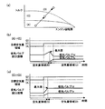
次に、本実施形態での過渡時における制御について図9を用いて説明する。ドライバ意図に応じてコントロールユニット13により図9(a)に示すようにエンジン回転およびトルクの様々な変化が発生する。
Next, the control at the time of transition in this embodiment is demonstrated using FIG. Depending on the driver's intention, the
図9(a)において目標空気量領域(A)から(C)に過渡変化する場合には、図9(b)に示されているように、まず、吸気バルブ7cのリフト量および開弁期間を増加させることにより、開口面積の増加を図る。吸気バルブ7cのリフト量および開弁期間が構成上の最大値に達し、吸気バルブ7cのみを作動させた場合に得られる最大の空気量に達すると、過渡変化中に、吸気バルブ7cのリフト量および開弁期間を減少させると共に、これに同期して吸気バルブ7dのリフト量および開弁期間を増加させて開口面積を増加させる。吸気バルブ7および吸気バルブ7dの開口面積の目標値は、ドライバ意図から決定される目標空気量により決定される。
In the case where a transient change is made from the target air amount region (A) to (C) in FIG. 9 (a), as shown in FIG. 9 (b), first, the lift amount and the valve opening period of the
この制御を行う理由は以下のとおりである。吸気バルブ7cの開口面積を最大値に保持したまま吸気バルブ7dの開口面積を増加させるように制御を行うとすると、吸気バルブ7cのみを作動させた場合に得られる最大の空気量から僅かに大きい空気量が目標である場合、吸気バルブ7dのリフト量および開弁期間を微小に増加させて開口面積を増加させる必要が生じるため、吸気バルブ7dのリフト量および開弁期間のばらつきによる吸入空気量のばらつきが発生する。
The reason for performing this control is as follows. If the control is performed so that the opening area of the
そこで、本実施形態では、吸気バルブ7cの開口面積を減少させることによって、空気量確保のために吸気バルブ7dの開口面積を増加させる必要を生じさせている。この制御により、吸気バルブ7dのリフト量および開弁期間を拡大することが可能となるため、吸気バルブ7dのリフト量および開弁期間のばらつきによる吸入空気量のばらつきを低減することができる。これにより、吸入空気量のばらつきに起因する混合気の空燃比の制御精度の低下が解消され、エンジン性能の向上が図られる。
Therefore, in this embodiment, it is necessary to increase the opening area of the
また、低空気量領域から高空気量領域に移る過渡変化時において、過渡変化前の運転状態およびドライバが意図する過渡変化後の運転状態に応じて、低空気量領域において作動させる吸気バルブ7cを通過する空気量の低下幅を変化させることもできる。
Further, at the time of a transient change from the low air amount region to the high air amount region, the
図9(a)において目標空気量領域(C)から(D)に変化する場合には、図9(c)に示されているように、吸気バルブ7cおよび吸気バルブ7dのリフト量および開弁期間を増加させることにより、開口面積の増加を図る。目標空気量領域(C)から(D)への過渡時では、吸気バルブ7cおよび吸気バルブ7dのリフト量および開弁期間が過渡中を通じて十分に大きい値を保持できるため、上述した目標空気量領域(A)から(C)の過渡変化時のような吸気バルブ制御を行う必要がない。吸気バルブ7cおよび吸気バルブ7dの開口面積の目標値は、ドライバ意図から決定される目標空気量により決定される。
In the case where the target air amount region (C) is changed to (D) in FIG. 9 (a), as shown in FIG. 9 (c), the lift amount and valve opening of the
なお、この実施形態でも、高空気量領域から低空気量領域に移る過渡時には、上述の制御とは、逆に、中、高空気量領域において作動させる吸気バルブ7dによる吸入空気量を過渡変化中に低下させると共に、低空気量領域において作動させる吸気バルブ7cによる吸入空気量を過渡変化中に増加させる。
In this embodiment as well, during the transition from the high air amount region to the low air amount region, the intake air amount by the
本実施形態では、一つの気筒に設けられた吸気バルブ7c、7dを通過する空気量がエンジンの運転領域により異なるため、本実施形態で示した吸気バルブ7c、7dの動作モード毎にそれぞれの吸気バルブの通過空気量に相応しい量の燃料を噴射する必要がある。したがって、この場合も、図6に示すように、一つの気筒に配設された吸気ポート毎に燃料噴射弁12を設けるのが理想的である。
In the present embodiment, the amount of air passing through the
100 内燃機関
1 シリンダブロック
2 コンロッド
3 シリンダ
4 ピストン
5 シリンダヘッド
6 燃焼室
7(7a、7b、7c、7d) 吸気バルブ
8 排気バルブ
9 点火プラグ
10 可変動弁機構
11(11a、11b) 吸気ポート
12 燃料噴射弁
DESCRIPTION OF
Claims (5)
前記複数個の吸気ポートを個別に開閉する複数個の吸気バルブは、第1の吸気バルブと第2の吸気バルブを含み、
前記吸入空気量に基づいた複数の吸気バルブの制御モード中の最も空気量が大きい高空気量領域の制御モードにおいて、該高空気量領域中を空気量により二つに分割した低い空気量の領域では、前記第2の吸気バルブのリフト量又は開弁期間及び位相を操作して、前記第2の吸気バルブを通過する空気量が、要求空気量から前記第1の吸気バルブを通過する空気量を減じた差分となるように制御することを特徴とする可変動弁式内燃機関の制御装置。 Each cylinder has a plurality of intake ports and an intake valve that individually opens and closes each intake port, and at least one of the lift amount and the valve opening period of the intake valve is continuously variably set. In a variable valve operating internal combustion engine that includes a valve mechanism and controls the amount of intake air by the intake valve,
The plurality of intake valves that individually open and close the plurality of intake ports include a first intake valve and a second intake valve,
In the control mode of the high air amount region where the air amount is the largest during the control mode of the plurality of intake valves based on the intake air amount, the low air amount region obtained by dividing the high air amount region into two by the air amount Then, by operating the lift amount or valve opening period and phase of the second intake valve, the amount of air passing through the second intake valve is changed from the required amount of air to the amount of air passing through the first intake valve. A control apparatus for a variable valve operating internal combustion engine, characterized in that control is performed so as to obtain a difference obtained by subtracting.
前記第1の吸気バルブには、予め定められたリフト量及び開弁期間を与え、
前記差分は、要求空気量から前記予め定められたリフト量及び開弁期間が与えられた時の前記第1の吸気バルブを通過する空気量を減じたものであることを特徴とする可変動弁式内燃機関の制御装置。 The control apparatus for a variable valve operating internal combustion engine according to claim 1,
The first intake valve is given a predetermined lift amount and a valve opening period,
The difference is obtained by subtracting the amount of air passing through the first intake valve when the predetermined lift amount and the valve opening period are given from the required air amount. Control device for an internal combustion engine.
前記複数個の吸気ポートを個別に開閉する複数個の吸気バルブは、第1の吸気バルブと、バルブシート径が該第1の吸気バルブより大きい第2の吸気バルブを含み、
前記吸入空気量の制御は、
前記第1の吸気バルブのみで空気量を制御する第1のモードと、
前記第2の吸気バルブのみで空気量を制御する第2のモードと、
前記第1の吸気バルブに予め定められたリフト量及び開弁期間を与えて、前記第2の吸気バルブのリフト量又は開弁期間及び位相を操作して、前記第2の吸気バルブを通過する空気量が、要求空気量から前記第1の吸気バルブを通過する空気量を減じた差分となるように制御する第3のモードと、
前記第2の吸気バルブのリフト量及び開弁期間を最大に保持しつつ、第1の吸気バルブで空気量を制御する第4のモードと、
を備えたことを特徴とする可変動弁式内燃機関の制御装置。 Each cylinder has a plurality of intake ports and an intake valve that individually opens and closes each intake port, and at least one of the lift amount and the valve opening period of the intake valve is continuously variably set. In a variable valve operating internal combustion engine that includes a valve mechanism and controls the amount of intake air by the intake valve,
The plurality of intake valves that individually open and close the plurality of intake ports include a first intake valve and a second intake valve having a valve seat diameter larger than the first intake valve,
The control of the intake air amount is as follows:
A first mode in which the air amount is controlled only by the first intake valve;
A second mode in which the amount of air is controlled only by the second intake valve;
A predetermined lift amount and valve opening period are given to the first intake valve, and the lift amount or valve opening period and phase of the second intake valve are manipulated to pass through the second intake valve. A third mode for controlling the air amount to be a difference obtained by subtracting the amount of air passing through the first intake valve from the required air amount;
A fourth mode of controlling the air amount with the first intake valve while maintaining the lift amount and the valve opening period of the second intake valve to the maximum;
A control apparatus for a variable valve operating internal combustion engine, comprising:
前記第1のモードから前記第2のモードに切換わる過渡期間において、前記第1の吸気バルブのリフト量及び開弁期間が最大に達すると、前記第1の吸気バルブの開口面積を減少させると共に同期して前記第2の吸気バルブの開口面積を増加させることを特徴とする可変動弁式内燃機関の制御装置。 In the control apparatus for a variable valve operating internal combustion engine according to claim 3,
When the lift amount and the valve opening period of the first intake valve reach the maximum during the transition period during which the first mode is switched to the second mode, the opening area of the first intake valve is reduced. A control apparatus for a variable valve operating internal combustion engine, wherein the opening area of the second intake valve is increased in synchronization.
前記第2のモードから前記第3のモードに切換わる過渡期間において、前記第2の吸気バルブのリフト量及び開弁期間が最大に達すると、前記第2の吸気バルブの開口面積を減少させると共に同期して前記第1の吸気バルブの開口面積を増加させることを特徴とする可変動弁式内燃機関の制御装置。 In the control apparatus for a variable valve operating internal combustion engine according to claim 3 or 4,
When the lift amount and the valve opening period of the second intake valve reach the maximum during the transition period from the second mode to the third mode, the opening area of the second intake valve is reduced. A control apparatus for a variable valve operating internal combustion engine, wherein the opening area of the first intake valve is increased synchronously.
Priority Applications (1)
| Application Number | Priority Date | Filing Date | Title |
|---|---|---|---|
| JP2007210956A JP4602383B2 (en) | 2007-08-13 | 2007-08-13 | Control device for variable valve internal combustion engine |
Applications Claiming Priority (1)
| Application Number | Priority Date | Filing Date | Title |
|---|---|---|---|
| JP2007210956A JP4602383B2 (en) | 2007-08-13 | 2007-08-13 | Control device for variable valve internal combustion engine |
Related Parent Applications (1)
| Application Number | Title | Priority Date | Filing Date |
|---|---|---|---|
| JP2003116054A Division JP4054711B2 (en) | 2003-04-21 | 2003-04-21 | Variable valve engine |
Publications (3)
| Publication Number | Publication Date |
|---|---|
| JP2007321767A JP2007321767A (en) | 2007-12-13 |
| JP2007321767A5 JP2007321767A5 (en) | 2008-01-31 |
| JP4602383B2 true JP4602383B2 (en) | 2010-12-22 |
Family
ID=38854776
Family Applications (1)
| Application Number | Title | Priority Date | Filing Date |
|---|---|---|---|
| JP2007210956A Expired - Fee Related JP4602383B2 (en) | 2007-08-13 | 2007-08-13 | Control device for variable valve internal combustion engine |
Country Status (1)
| Country | Link |
|---|---|
| JP (1) | JP4602383B2 (en) |
Families Citing this family (2)
| Publication number | Priority date | Publication date | Assignee | Title |
|---|---|---|---|---|
| JP5194814B2 (en) * | 2008-01-15 | 2013-05-08 | マツダ株式会社 | Control method and apparatus for internal combustion engine |
| JP5104463B2 (en) * | 2008-03-28 | 2012-12-19 | 株式会社デンソー | Fuel injection device |
Citations (3)
| Publication number | Priority date | Publication date | Assignee | Title |
|---|---|---|---|---|
| JPH0828284A (en) * | 1994-07-20 | 1996-01-30 | Yamaha Motor Co Ltd | Intake device for four-cycle engine |
| JP2000087766A (en) * | 1998-09-08 | 2000-03-28 | Nissan Motor Co Ltd | Control unit for variable valve engine |
| JP2001159322A (en) * | 1999-12-02 | 2001-06-12 | Nissan Motor Co Ltd | Intake device for engine |
-
2007
- 2007-08-13 JP JP2007210956A patent/JP4602383B2/en not_active Expired - Fee Related
Patent Citations (3)
| Publication number | Priority date | Publication date | Assignee | Title |
|---|---|---|---|---|
| JPH0828284A (en) * | 1994-07-20 | 1996-01-30 | Yamaha Motor Co Ltd | Intake device for four-cycle engine |
| JP2000087766A (en) * | 1998-09-08 | 2000-03-28 | Nissan Motor Co Ltd | Control unit for variable valve engine |
| JP2001159322A (en) * | 1999-12-02 | 2001-06-12 | Nissan Motor Co Ltd | Intake device for engine |
Also Published As
| Publication number | Publication date |
|---|---|
| JP2007321767A (en) | 2007-12-13 |
Similar Documents
| Publication | Publication Date | Title |
|---|---|---|
| US7357119B2 (en) | Variable valve type internal combustion engine and control method thereof | |
| US7377260B2 (en) | Method and device for controlling an internal combustion engine | |
| EP1384875A2 (en) | Fuel control system and method of engine | |
| JP2005207273A (en) | Variable compression ratio internal combustion engine | |
| JP6011714B2 (en) | Control device and control method for internal combustion engine | |
| JP4277883B2 (en) | In-cylinder injection spark ignition internal combustion engine | |
| JP2011241756A (en) | Apparatus for control of internal combustion engine | |
| US20160348606A1 (en) | Control apparatus for internal combustion engine | |
| JP2000073803A (en) | Cylinder injection gasoline engine | |
| US9624862B2 (en) | Control apparatus for internal combustion engine | |
| JP4602383B2 (en) | Control device for variable valve internal combustion engine | |
| JP5273310B2 (en) | Control device for internal combustion engine | |
| JP5282636B2 (en) | Control device for internal combustion engine | |
| US7849834B2 (en) | Method and apparatus for controlling emissions from internal combustion engines | |
| JP2000291476A (en) | Cylinder injection internal combustion engine | |
| JP2006336620A (en) | Fuel injection control device for internal combustion engine | |
| JP6252006B2 (en) | Engine control device | |
| JP2004316545A (en) | Control device by cylinder for compression ignition type internal combustion engine | |
| JP2006132399A (en) | Control device and control method for an engine with supercharger | |
| JP2007278208A (en) | Control device for internal combustion engine | |
| US8219301B2 (en) | Control device for internal combustion engine | |
| JP2003148182A (en) | Control device of internal combustion engine | |
| JP2009264280A (en) | Control device of cylinder fuel injection engine | |
| JP2006336621A (en) | Control device for internal combustion engine | |
| JP2008115836A (en) | Cylinder injection control device |
Legal Events
| Date | Code | Title | Description |
|---|---|---|---|
| A621 | Written request for application examination |
Free format text: JAPANESE INTERMEDIATE CODE: A621 Effective date: 20070911 |
|
| A521 | Written amendment |
Free format text: JAPANESE INTERMEDIATE CODE: A523 Effective date: 20071130 |
|
| A711 | Notification of change in applicant |
Free format text: JAPANESE INTERMEDIATE CODE: A712 Effective date: 20100115 |
|
| A131 | Notification of reasons for refusal |
Free format text: JAPANESE INTERMEDIATE CODE: A131 Effective date: 20100119 |
|
| A521 | Written amendment |
Free format text: JAPANESE INTERMEDIATE CODE: A523 Effective date: 20100323 |
|
| A131 | Notification of reasons for refusal |
Free format text: JAPANESE INTERMEDIATE CODE: A131 Effective date: 20100713 |
|
| A521 | Written amendment |
Free format text: JAPANESE INTERMEDIATE CODE: A523 Effective date: 20100826 |
|
| TRDD | Decision of grant or rejection written | ||
| A01 | Written decision to grant a patent or to grant a registration (utility model) |
Free format text: JAPANESE INTERMEDIATE CODE: A01 Effective date: 20100914 |
|
| A01 | Written decision to grant a patent or to grant a registration (utility model) |
Free format text: JAPANESE INTERMEDIATE CODE: A01 |
|
| A61 | First payment of annual fees (during grant procedure) |
Free format text: JAPANESE INTERMEDIATE CODE: A61 Effective date: 20100929 |
|
| FPAY | Renewal fee payment (event date is renewal date of database) |
Free format text: PAYMENT UNTIL: 20131008 Year of fee payment: 3 |
|
| R150 | Certificate of patent or registration of utility model |
Ref document number: 4602383 Country of ref document: JP Free format text: JAPANESE INTERMEDIATE CODE: R150 Free format text: JAPANESE INTERMEDIATE CODE: R150 |
|
| LAPS | Cancellation because of no payment of annual fees |