JP2005299419A - Exhaust muffler with exhaust emission control function for engine - Google Patents
Exhaust muffler with exhaust emission control function for engine Download PDFInfo
- Publication number
- JP2005299419A JP2005299419A JP2004113392A JP2004113392A JP2005299419A JP 2005299419 A JP2005299419 A JP 2005299419A JP 2004113392 A JP2004113392 A JP 2004113392A JP 2004113392 A JP2004113392 A JP 2004113392A JP 2005299419 A JP2005299419 A JP 2005299419A
- Authority
- JP
- Japan
- Prior art keywords
- exhaust
- chamber
- muffler
- partition member
- exhaust gas
- Prior art date
- Legal status (The legal status is an assumption and is not a legal conclusion. Google has not performed a legal analysis and makes no representation as to the accuracy of the status listed.)
- Granted
Links
Images

Classifications
-
- F—MECHANICAL ENGINEERING; LIGHTING; HEATING; WEAPONS; BLASTING
- F01—MACHINES OR ENGINES IN GENERAL; ENGINE PLANTS IN GENERAL; STEAM ENGINES
- F01N—GAS-FLOW SILENCERS OR EXHAUST APPARATUS FOR MACHINES OR ENGINES IN GENERAL; GAS-FLOW SILENCERS OR EXHAUST APPARATUS FOR INTERNAL COMBUSTION ENGINES
- F01N13/00—Exhaust or silencing apparatus characterised by constructional features ; Exhaust or silencing apparatus, or parts thereof, having pertinent characteristics not provided for in, or of interest apart from, groups F01N1/00 - F01N5/00, F01N9/00, F01N11/00
- F01N13/18—Construction facilitating manufacture, assembly, or disassembly
- F01N13/1861—Construction facilitating manufacture, assembly, or disassembly the assembly using parts formed by casting or moulding
-
- C—CHEMISTRY; METALLURGY
- C12—BIOCHEMISTRY; BEER; SPIRITS; WINE; VINEGAR; MICROBIOLOGY; ENZYMOLOGY; MUTATION OR GENETIC ENGINEERING
- C12G—WINE; PREPARATION THEREOF; ALCOHOLIC BEVERAGES; PREPARATION OF ALCOHOLIC BEVERAGES NOT PROVIDED FOR IN SUBCLASSES C12C OR C12H
- C12G3/00—Preparation of other alcoholic beverages
- C12G3/04—Preparation of other alcoholic beverages by mixing, e.g. for preparation of liqueurs
-
- F—MECHANICAL ENGINEERING; LIGHTING; HEATING; WEAPONS; BLASTING
- F01—MACHINES OR ENGINES IN GENERAL; ENGINE PLANTS IN GENERAL; STEAM ENGINES
- F01N—GAS-FLOW SILENCERS OR EXHAUST APPARATUS FOR MACHINES OR ENGINES IN GENERAL; GAS-FLOW SILENCERS OR EXHAUST APPARATUS FOR INTERNAL COMBUSTION ENGINES
- F01N1/00—Silencing apparatus characterised by method of silencing
- F01N1/08—Silencing apparatus characterised by method of silencing by reducing exhaust energy by throttling or whirling
- F01N1/083—Silencing apparatus characterised by method of silencing by reducing exhaust energy by throttling or whirling using transversal baffles defining a tortuous path for the gases or successively throttling gas flow
-
- F—MECHANICAL ENGINEERING; LIGHTING; HEATING; WEAPONS; BLASTING
- F01—MACHINES OR ENGINES IN GENERAL; ENGINE PLANTS IN GENERAL; STEAM ENGINES
- F01N—GAS-FLOW SILENCERS OR EXHAUST APPARATUS FOR MACHINES OR ENGINES IN GENERAL; GAS-FLOW SILENCERS OR EXHAUST APPARATUS FOR INTERNAL COMBUSTION ENGINES
- F01N1/00—Silencing apparatus characterised by method of silencing
- F01N1/08—Silencing apparatus characterised by method of silencing by reducing exhaust energy by throttling or whirling
- F01N1/089—Silencing apparatus characterised by method of silencing by reducing exhaust energy by throttling or whirling using two or more expansion chambers in series
-
- F—MECHANICAL ENGINEERING; LIGHTING; HEATING; WEAPONS; BLASTING
- F01—MACHINES OR ENGINES IN GENERAL; ENGINE PLANTS IN GENERAL; STEAM ENGINES
- F01N—GAS-FLOW SILENCERS OR EXHAUST APPARATUS FOR MACHINES OR ENGINES IN GENERAL; GAS-FLOW SILENCERS OR EXHAUST APPARATUS FOR INTERNAL COMBUSTION ENGINES
- F01N13/00—Exhaust or silencing apparatus characterised by constructional features ; Exhaust or silencing apparatus, or parts thereof, having pertinent characteristics not provided for in, or of interest apart from, groups F01N1/00 - F01N5/00, F01N9/00, F01N11/00
- F01N13/002—Apparatus adapted for particular uses, e.g. for portable devices driven by machines or engines
-
- F—MECHANICAL ENGINEERING; LIGHTING; HEATING; WEAPONS; BLASTING
- F01—MACHINES OR ENGINES IN GENERAL; ENGINE PLANTS IN GENERAL; STEAM ENGINES
- F01N—GAS-FLOW SILENCERS OR EXHAUST APPARATUS FOR MACHINES OR ENGINES IN GENERAL; GAS-FLOW SILENCERS OR EXHAUST APPARATUS FOR INTERNAL COMBUSTION ENGINES
- F01N13/00—Exhaust or silencing apparatus characterised by constructional features ; Exhaust or silencing apparatus, or parts thereof, having pertinent characteristics not provided for in, or of interest apart from, groups F01N1/00 - F01N5/00, F01N9/00, F01N11/00
- F01N13/009—Exhaust or silencing apparatus characterised by constructional features ; Exhaust or silencing apparatus, or parts thereof, having pertinent characteristics not provided for in, or of interest apart from, groups F01N1/00 - F01N5/00, F01N9/00, F01N11/00 having two or more separate purifying devices arranged in series
- F01N13/0097—Exhaust or silencing apparatus characterised by constructional features ; Exhaust or silencing apparatus, or parts thereof, having pertinent characteristics not provided for in, or of interest apart from, groups F01N1/00 - F01N5/00, F01N9/00, F01N11/00 having two or more separate purifying devices arranged in series the purifying devices are arranged in a single housing
-
- F—MECHANICAL ENGINEERING; LIGHTING; HEATING; WEAPONS; BLASTING
- F01—MACHINES OR ENGINES IN GENERAL; ENGINE PLANTS IN GENERAL; STEAM ENGINES
- F01N—GAS-FLOW SILENCERS OR EXHAUST APPARATUS FOR MACHINES OR ENGINES IN GENERAL; GAS-FLOW SILENCERS OR EXHAUST APPARATUS FOR INTERNAL COMBUSTION ENGINES
- F01N13/00—Exhaust or silencing apparatus characterised by constructional features ; Exhaust or silencing apparatus, or parts thereof, having pertinent characteristics not provided for in, or of interest apart from, groups F01N1/00 - F01N5/00, F01N9/00, F01N11/00
- F01N13/18—Construction facilitating manufacture, assembly, or disassembly
- F01N13/1888—Construction facilitating manufacture, assembly, or disassembly the housing of the assembly consisting of two or more parts, e.g. two half-shells
-
- F—MECHANICAL ENGINEERING; LIGHTING; HEATING; WEAPONS; BLASTING
- F01—MACHINES OR ENGINES IN GENERAL; ENGINE PLANTS IN GENERAL; STEAM ENGINES
- F01N—GAS-FLOW SILENCERS OR EXHAUST APPARATUS FOR MACHINES OR ENGINES IN GENERAL; GAS-FLOW SILENCERS OR EXHAUST APPARATUS FOR INTERNAL COMBUSTION ENGINES
- F01N3/00—Exhaust or silencing apparatus having means for purifying, rendering innocuous, or otherwise treating exhaust
- F01N3/08—Exhaust or silencing apparatus having means for purifying, rendering innocuous, or otherwise treating exhaust for rendering innocuous
- F01N3/10—Exhaust or silencing apparatus having means for purifying, rendering innocuous, or otherwise treating exhaust for rendering innocuous by thermal or catalytic conversion of noxious components of exhaust
- F01N3/24—Exhaust or silencing apparatus having means for purifying, rendering innocuous, or otherwise treating exhaust for rendering innocuous by thermal or catalytic conversion of noxious components of exhaust characterised by constructional aspects of converting apparatus
- F01N3/28—Construction of catalytic reactors
- F01N3/2882—Catalytic reactors combined or associated with other devices, e.g. exhaust silencers or other exhaust purification devices
- F01N3/2885—Catalytic reactors combined or associated with other devices, e.g. exhaust silencers or other exhaust purification devices with exhaust silencers in a single housing
-
- F—MECHANICAL ENGINEERING; LIGHTING; HEATING; WEAPONS; BLASTING
- F01—MACHINES OR ENGINES IN GENERAL; ENGINE PLANTS IN GENERAL; STEAM ENGINES
- F01N—GAS-FLOW SILENCERS OR EXHAUST APPARATUS FOR MACHINES OR ENGINES IN GENERAL; GAS-FLOW SILENCERS OR EXHAUST APPARATUS FOR INTERNAL COMBUSTION ENGINES
- F01N2210/00—Combination of methods of silencing
-
- F—MECHANICAL ENGINEERING; LIGHTING; HEATING; WEAPONS; BLASTING
- F01—MACHINES OR ENGINES IN GENERAL; ENGINE PLANTS IN GENERAL; STEAM ENGINES
- F01N—GAS-FLOW SILENCERS OR EXHAUST APPARATUS FOR MACHINES OR ENGINES IN GENERAL; GAS-FLOW SILENCERS OR EXHAUST APPARATUS FOR INTERNAL COMBUSTION ENGINES
- F01N2230/00—Combination of silencers and other devices
- F01N2230/04—Catalytic converters
-
- F—MECHANICAL ENGINEERING; LIGHTING; HEATING; WEAPONS; BLASTING
- F01—MACHINES OR ENGINES IN GENERAL; ENGINE PLANTS IN GENERAL; STEAM ENGINES
- F01N—GAS-FLOW SILENCERS OR EXHAUST APPARATUS FOR MACHINES OR ENGINES IN GENERAL; GAS-FLOW SILENCERS OR EXHAUST APPARATUS FOR INTERNAL COMBUSTION ENGINES
- F01N2240/00—Combination or association of two or more different exhaust treating devices, or of at least one such device with an auxiliary device, not covered by indexing codes F01N2230/00 or F01N2250/00, one of the devices being
- F01N2240/20—Combination or association of two or more different exhaust treating devices, or of at least one such device with an auxiliary device, not covered by indexing codes F01N2230/00 or F01N2250/00, one of the devices being a flow director or deflector
-
- F—MECHANICAL ENGINEERING; LIGHTING; HEATING; WEAPONS; BLASTING
- F01—MACHINES OR ENGINES IN GENERAL; ENGINE PLANTS IN GENERAL; STEAM ENGINES
- F01N—GAS-FLOW SILENCERS OR EXHAUST APPARATUS FOR MACHINES OR ENGINES IN GENERAL; GAS-FLOW SILENCERS OR EXHAUST APPARATUS FOR INTERNAL COMBUSTION ENGINES
- F01N2450/00—Methods or apparatus for fitting, inserting or repairing different elements
- F01N2450/30—Removable or rechangeable blocks or cartridges, e.g. for filters
-
- F—MECHANICAL ENGINEERING; LIGHTING; HEATING; WEAPONS; BLASTING
- F01—MACHINES OR ENGINES IN GENERAL; ENGINE PLANTS IN GENERAL; STEAM ENGINES
- F01N—GAS-FLOW SILENCERS OR EXHAUST APPARATUS FOR MACHINES OR ENGINES IN GENERAL; GAS-FLOW SILENCERS OR EXHAUST APPARATUS FOR INTERNAL COMBUSTION ENGINES
- F01N2490/00—Structure, disposition or shape of gas-chambers
- F01N2490/08—Two or more expansion chambers in series separated by apertured walls only
-
- F—MECHANICAL ENGINEERING; LIGHTING; HEATING; WEAPONS; BLASTING
- F01—MACHINES OR ENGINES IN GENERAL; ENGINE PLANTS IN GENERAL; STEAM ENGINES
- F01N—GAS-FLOW SILENCERS OR EXHAUST APPARATUS FOR MACHINES OR ENGINES IN GENERAL; GAS-FLOW SILENCERS OR EXHAUST APPARATUS FOR INTERNAL COMBUSTION ENGINES
- F01N2510/00—Surface coverings
- F01N2510/06—Surface coverings for exhaust purification, e.g. catalytic reaction
-
- F—MECHANICAL ENGINEERING; LIGHTING; HEATING; WEAPONS; BLASTING
- F01—MACHINES OR ENGINES IN GENERAL; ENGINE PLANTS IN GENERAL; STEAM ENGINES
- F01N—GAS-FLOW SILENCERS OR EXHAUST APPARATUS FOR MACHINES OR ENGINES IN GENERAL; GAS-FLOW SILENCERS OR EXHAUST APPARATUS FOR INTERNAL COMBUSTION ENGINES
- F01N2590/00—Exhaust or silencing apparatus adapted to particular use, e.g. for military applications, airplanes, submarines
- F01N2590/06—Exhaust or silencing apparatus adapted to particular use, e.g. for military applications, airplanes, submarines for hand-held tools or portables devices
Abstract
Description
本発明は,主として汎用エンジンに適用される排気浄化機能付き排気マフラの改良に関する。 The present invention relates to an improvement of an exhaust muffler having an exhaust purification function mainly applied to a general-purpose engine.
従来,エンジン用排気浄化機能付き排気マフラとして,中空のマフラ本体の内面に,排気浄化用触媒を担持した多孔質体を固着したものが下記特許文献1に開示されるように知られており,また中空のマフラ本体内の排気通路に,排気浄化用触媒を担持したハニカム体若しくは多孔質体を介裝したものが下記特許文献2に開示されるように知られている。
特許文献1に開示されるようなものでは,排気浄化用触媒を担持した多孔質体がマフラ本体に内壁に固着されているため,排気浄化用触媒で生じる排気浄化反応熱によりマフラ本体が過熱され,排気マフラの隣接機器に熱害が及ぶ虞があり,また特許文献1に開示されるようなものでは,構造が複雑でコスト高となるのみならず,ハニカム体若しくは多孔質体において一気に排気浄化を行うため,排気温度の上昇が激しく,またマフラ本体のハニカム体若しくは多孔質体に近接した部分が特に過熱されることになり,さらにハニカム体若しくは多孔質体よるエンジンの背圧の上昇により多少とも出力低下を伴うので,特に比較的小排気量の汎用エンジンには不向きである。 In the one disclosed in Patent Document 1, since the porous body carrying the exhaust purification catalyst is fixed to the inner wall of the muffler body, the muffler body is overheated by the exhaust purification reaction heat generated in the exhaust purification catalyst. In addition, there is a risk of heat damage to adjacent equipment of the exhaust muffler, and the one disclosed in Patent Document 1 not only makes the structure complicated and expensive, but also exhausts the exhaust gas from the honeycomb body or porous body at once. As a result, the exhaust temperature rises rapidly, and the portion of the muffler body close to the honeycomb body or porous body is particularly overheated. Both are accompanied by a decrease in output, and are not suitable for general-purpose engines with a relatively small displacement.
本発明は,かゝる事情に鑑みてなされたもので,隣接機器への熱害が少なく,しかも構造が簡単で低コストであり,その上,エンジン出力の低下が少ない,エンジン用排気浄化機能付き排気マフラを提供することを目的とする。 The present invention has been made in view of such circumstances, and has an exhaust gas purification function for an engine that causes less heat damage to adjacent equipment, has a simple structure and is low in cost, and has little reduction in engine output. An object is to provide an exhaust muffler with a valve.
上記目的を達成するために,本発明は,中空のマフラ本体内を仕切り部材により第1排気室及び第2排気室に区画すると共に,この仕切り部材に第3排気室を形成し,エンジンの排ガスを第1排気室に導入する排気入口をマフラ本体に設け,第1及び第2排気室間を連通する第1連通孔と,第2排気室を第3排気室に連通する第2連通孔とを仕切り部材に設け,第3排気室を排気出口管を介して大気に開放し,仕切り部材の第1及び第2排気室に臨む外表面,並びに第3排気室に臨む内表面に排気浄化用触媒を担持し,マフラ本体の内面は排気浄化用触媒の非担持面としたことを第1の特徴とする。 In order to achieve the above object, the present invention divides the inside of a hollow muffler body into a first exhaust chamber and a second exhaust chamber by a partition member, and forms a third exhaust chamber in the partition member. An exhaust inlet for introducing the first exhaust chamber into the first exhaust chamber is provided in the muffler body, a first communication hole that communicates between the first and second exhaust chambers, a second communication hole that communicates the second exhaust chamber with the third exhaust chamber, Is provided on the partition member, the third exhaust chamber is opened to the atmosphere through the exhaust outlet pipe, and the outer surface of the partition member facing the first and second exhaust chambers and the inner surface facing the third exhaust chamber are used for exhaust purification. The first feature is that the catalyst is supported and the inner surface of the muffler body is a non-supported surface of the exhaust purification catalyst.
また本発明は,第1の特徴に加えて,第1排気室には,排気入口から第1排気室に流入した排ガスを拡散する第1拡散板を配設したことを第2の特徴とする。 In addition to the first feature, the present invention has a second feature that the first exhaust chamber is provided with a first diffusion plate for diffusing the exhaust gas flowing into the first exhaust chamber from the exhaust inlet. .
さらに本発明は,第1又は第2の特徴に加えて,第2排気室には,第1連通孔から第2排気室に流入した排ガスを拡散させながら第3排気室側へ誘導する第2拡散板を配設したことを第3の特徴とする。 Furthermore, in addition to the first or second feature, the present invention provides a second exhaust chamber in which the exhaust gas flowing into the second exhaust chamber from the first communication hole is guided to the third exhaust chamber side while diffusing. The third feature is that a diffusion plate is provided.
さらにまた本発明は,第1の特徴に加えて,排気出口管の内面は排気浄化用触媒の非担持面としたことを第4の特徴とする。 Furthermore, in addition to the first feature, the present invention has a fourth feature that the inner surface of the exhaust outlet pipe is a non-supporting surface of the exhaust purification catalyst.
本発明の第1の特徴によれば,エンジンの排ガスは,第1排気室〜第3排気室を順次移動する間に,仕切り部材の外表面及び内表面において浄化作用を段階的に受けることになり,浄化反応熱による排気温度の上昇も,仕切り部材自体の温度上昇も極力少なくすることができる。しかもマフラ本体の内面は,排気浄化用触媒の非担持面となっているから,マフラ本体の過熱を回避し得て,隣接機器への熱害を簡単に防ぐことができる。その上,触媒担持専用のハニカム体若しくは多孔質体は使用しないので,構造が簡単で安価に提供することができる。 According to the first feature of the present invention, the exhaust gas of the engine is subjected to the purification action in stages on the outer surface and the inner surface of the partition member while moving sequentially from the first exhaust chamber to the third exhaust chamber. Thus, the exhaust temperature rise due to the purification reaction heat and the temperature rise of the partition member itself can be minimized. Moreover, since the inner surface of the muffler main body is a non-supporting surface for the exhaust purification catalyst, overheating of the muffler main body can be avoided and thermal damage to adjacent equipment can be easily prevented. In addition, since a honeycomb body or a porous body dedicated to catalyst support is not used, the structure is simple and can be provided at low cost.
また排気出口管の長さを,エンジンの常用回転数に合わせて適当に設定することにより,エンジンの排気脈動を有効に利用して外気を第3排気室〜第1排気室へと引き込むことができ,酸化反応による排気浄化性能の向上を図ることができる。 In addition, by appropriately setting the length of the exhaust outlet pipe in accordance with the normal engine speed, the exhaust pulsation of the engine can be effectively used to draw outside air from the third exhaust chamber to the first exhaust chamber. It is possible to improve exhaust gas purification performance by oxidation reaction.
さらに仕切り部材の外表面及び内表面に担持した排気浄化用触媒は,排ガスの流れを殆ど妨げないので,エンジンの背圧の上昇を抑えて出力低下を極力防ぐことができる。 Furthermore, since the exhaust purification catalyst carried on the outer surface and inner surface of the partition member hardly disturbs the flow of exhaust gas, it is possible to suppress an increase in engine back pressure and prevent a decrease in output as much as possible.
また本発明の第2の特徴によれば,排気入口から第1排気室に流入した排ガスを第1拡散板により第1排気室の全体に拡散させて,触媒を担持した仕切り部材の外表面に万遍なく接触させ,それを効果的に浄化することができる。しかも,排気入口から第1排気室に流入した排ガスの仕切り部材への衝突がないから,仕切り部材の外表面が局部的に過熱されることはなく,仕切り部材の耐久性を高めることができる。 Further, according to the second feature of the present invention, the exhaust gas flowing into the first exhaust chamber from the exhaust inlet is diffused throughout the first exhaust chamber by the first diffusion plate, and is applied to the outer surface of the partition member carrying the catalyst. It can be contacted evenly and purified effectively. In addition, since the exhaust gas flowing into the first exhaust chamber from the exhaust inlet does not collide with the partition member, the outer surface of the partition member is not locally heated, and the durability of the partition member can be improved.
さらに本発明の第3の特徴によれば,第1排気室から第1連通孔を通して第2排気室に移行した排ガスを,第2拡散板により拡散させながら全体的には第3排気室側へ誘導するので,排ガスは,触媒を担持した仕切り部材の第2排気室に臨む外表面に万遍なく接触して再度浄化された後,第2連通孔を通過して第3排気室にスムーズに移行することができ,排気浄化効率を高めることができる。 Further, according to the third feature of the present invention, the exhaust gas transferred from the first exhaust chamber to the second exhaust chamber through the first communication hole is diffused by the second diffusion plate, and is entirely directed to the third exhaust chamber side. Since the exhaust gas is purified by contacting the outer surface of the partition member carrying the catalyst that faces the second exhaust chamber, the exhaust gas passes through the second communication hole and smoothly enters the third exhaust chamber. The exhaust gas purification efficiency can be increased.
さらにまた本発明の第4の特徴によれば,排気出口管を通過する排ガスの温度上昇を極力抑え,排ガスによる隣接機器への影響を防ぐことができる。 Furthermore, according to the fourth feature of the present invention, the temperature rise of the exhaust gas passing through the exhaust outlet pipe can be suppressed as much as possible, and the influence of the exhaust gas on adjacent devices can be prevented.
本発明の実施の形態を,添付図面に示す本発明の好適な実施例に基づいて説明する。 Embodiments of the present invention will be described based on preferred embodiments of the present invention shown in the accompanying drawings.
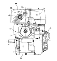
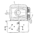
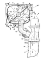
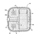
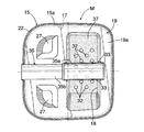
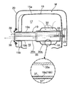
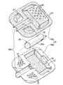
図1は本発明に係る排気マフラを備えた汎用エンジンの正面図,図2は図1の2矢視図,図3は図1の3矢視図,図4は図3の4−4線に沿うエンジンの一部及び排気マフラの断面図,図5は図4の5−5線断面図,図6は図4の6−6線断面図,図7は図4の7−7線断面図,図8は上記排気マフラ内の仕切り部材の分解斜視図である。
1 is a front view of a general-purpose engine equipped with an exhaust muffler according to the present invention, FIG. 2 is a view taken in the direction of
先ず,図1〜図3に示すように,汎用エンジンEのエンジン本体1は,下面に据え付けフランジ2aを有してクランク軸4を水平に支承するクランクケース2と,このクランクケース2から一側方に斜め上向きに突出するシリンダ3とからなっており,クランクケース2の正面側には,クランク軸4をクランキングするリコイル式エンジンスタータ5が取り付けられる。またエンジン本体1には,クランクケース2の上方に配置される燃料タンクTと,シリンダ3の上方で燃料タンクTに隣接する吸気エアクリーナA及び排気マフラMとが取り付けられる。
First, as shown in FIGS. 1 to 3, the engine body 1 of the general-purpose engine E includes a
図4において,前記シリンダ3は,クランクケース2に連なるシリンダブロック3aと,このシリンダブロック3aの端面に接合され,シリンダブロック3a内のピストン6が臨む燃焼室7を有するシリンダヘッド3bと,このシリンダヘッド3bに接合されて,それとの間に動弁室8を画成するヘッドカバー3cとで構成され,シリンダヘッド3bには,燃焼室7に連なる排気ポート9に連通する排気管10の下端連結フランジ10aがボルト12により固着され,この排気管10に排気マフラMが連結される。
4, the
上記排気マフラMについて,図4〜図8により説明する。 The exhaust muffler M will be described with reference to FIGS.
図4及び図5において,排気マフラMは,箱型のマフラ本体15と,このマフラ本体15内に一つの対角線に沿って配置されて,その内部を第1排気室16及び第2排気室17に区画する仕切り部材19と,マフラ本体15の排気管10側下面を除く外面を覆って,マフラ本体15に複数のタッピングねじ21,21…により固着される合成樹脂製又は鋼板製のマフラカバー20とからなっている。
4 and 5, the exhaust muffler M is arranged in a box-shaped muffler
マフラ本体15は,一つの対角線に沿って分割される鋼板製の下部マフラ半体15b及び上部マフラ半体15aからなっており,上部マフラ半体15a外周のかしめ部22を,下部マフラ半体15b外周のフランジ部23にかしめることにより,両マフラ半体15a,15bは結合される。その際,かしめ部22及びフランジ部23間に前記仕切り部材19の外周部を挟持することにより,仕切り部材19はマフラ本体15に結合される。
The
図4に示すように,下部マフラ半体15bには,排気管10を第1排気室16に開口させる排気入口25が設けられ,この排気入口25を覆って排気入口25及び仕切り部材19間を遮る第1拡散板26が下部マフラ半体15bの内壁に接合され,この第1拡散板26により,排気入口25から第1排気室16に流入した排ガスを拡散させて,排ガスの仕切り部材19への衝突を防ぐようになっている。
As shown in FIG. 4, the
第1拡散板26には,下部マフラ半体15bを貫通する連結ボルト28が溶接されており,この連結ボルト28とこれに螺合するナット29とにより,第1拡散板26及び下部マフラ半体15bは,前記排気管10の上端連結フランジ10bに固着される。こうして第1拡散板26は下部マフラ半体15bの補強板を兼ねることになる。
A connecting
図5〜図8に示すように,仕切り部材19は,互いに接合される鋼板製の上部仕切り半体19a及び下部仕切り半体19bからなっており,下部仕切り半体19bの一半部には,互いに間隔を置いて並ぶ二組の第1連通孔31,31…;31,31…群が設けられ,これらによって第1及び第2排気室16,17間が連通される。また上部仕切り半体19aの一半部には,上記二組の第1連通孔31,31…;31,31…群を覆うように配置されて,第1連通孔31,31…;31,31…群から第2排気室17に流入した排ガスを後述の第3排気室18側へ誘導する一対の第2拡散板27,27が切り起こしにより形成される。
As shown in FIGS. 5 to 8, the
両仕切り半体19a,19bの他半部間には,それらを外方に膨出させて第3排気室18が形成されると共に,第2排気室17をこの第3排気室18に連通する第2連通孔32,32…群が上部仕切り半体19aに設けられる。
A
そして,第3排気室18は,二組の第1連通孔31,31…;31,31…群の間を通る排気出口管35を介して大気に開放される。
The
上記排気出口管35は,第3排気室18を横断するように上部及び下部仕切り半体19a,19b間に支持されるパイプ部材35aと,このパイプ部材35aに連通するように上部及び下部仕切り半体19a,19b間に膨出形成されるパイプ状部35bとからなっており,そのパイプ状部35bが二組の第1連通孔31,31…;31,31…群の間を通って上部及び下部マフラ半体15a,15bの接合面間を貫き,外部に突出するように配置される。パイプ部材35aの一端には,第3排気室18を排気出口管35に連通する一つ又は複数の切欠き状の第3連通孔33が設けられる。
The
而して,仕切り部材19の第1及び第2排気室16,17に臨む外表面,並びに第3排気室18に臨む内表面には排気浄化用触媒37が担持され,マフラ本体15の内面及び排気出口管35は排気浄化用触媒の非担持面とされる。排気浄化用触媒37は,酸化触媒としてのPt又はPdと,還元触媒としてのRhとからなっている。したがって,排気中のHC,COは,酸化触媒により酸化処理され,また排気中のNOxは還元触媒により還元処理されることになる。
Thus, the
マフラカバー20には,排気出口管35の外端開口部に対向する通孔38が設けられると共に,この通孔38を横切る金網製のスパークアレスタ39が付設される。
The
次に,この実施例の作用について説明する。 Next, the operation of this embodiment will be described.
エンジンEの排気行程で,燃焼室7を出た排ガスは,排気ポート9,排気管10及び排気入口25を順次経て第1排気室16に流入する。そのとき排ガスは,第1拡散板26に衝突することで,仕切り部材19へ衝突することなく,第1排気室16の全体に拡散することになる。その結果,排ガスは,触媒37を担持した仕切り部材19の第1排気室16に臨む外表面に万遍なく接触して,効果的に浄化される。しかも排気入口25から第1排気室16に流入した排ガスが仕切り部材19に直接衝突することがないから,仕切り部材19の外表面が局部的に過熱されることもなく,仕切り部材19の耐久性を高めることができる。
In the exhaust stroke of the engine E, the exhaust gas exiting the combustion chamber 7 flows into the
第1排気室16で浄化された排ガスは,二組の第1連通孔31,31…;31,31…群から第2排気室17に移行するが,その際,一対の第2拡散板27,27により拡散されながら全体的には第3排気室18側へ誘導される。その結果,排ガスは,触媒37を担持した仕切り部材19の第2排気室17に臨む外表面に万遍なく接触して再度浄化された後,第2連通孔32,32…群を通過して第3排気室18にスムーズに移行することができる。そして,その排ガスは,触媒37を担持した仕切り部材19の第3排気室18に臨む内表面に接触して更に浄化された後,第3連通孔33から排気出口管35を経由して大気に排出される。
The exhaust gas purified in the
このように,排ガスが第1排気室16〜第3排気室18を順次移動する間に,仕切り部材19の外表面及び内表面において浄化作用を段階的に受けるので,浄化反応熱による排気温度の上昇も,仕切り部材19自体の温度上昇も比較的少ない。しかもマフラ本体15の内面は,排気浄化用触媒の非担持面となっているから,マフラ本体15の過熱を回避でき,したがって排気マフラMには,通常の排気マフラの場合と同様に,その外面を覆う一層の簡単なマフラカバー20を取り付けることにより,燃料タンクT等の隣接機器に熱害を及ぼすことを回避することができる。その上,触媒担持専用のハニカム体若しくは多孔質体は使用しないので,構造が極めて簡単で安価である。
As described above, the purification action is received in stages on the outer surface and the inner surface of the
さらに第3排気室18を大気に開放する排気出口管35の内面も,排気浄化用触媒の非担持面となっているから,排気出口管35を通過する排ガスの温度上昇を極力抑え,スパークアレスタ39の耐久性を確保すると共に,排ガスによる隣接機器への影響を防ぐことができる。
Further, since the inner surface of the
その上,排気出口管35の長さを,エンジンEの常用回転数に合わせて適当に設定することにより,エンジンEの排気脈動を有効に利用して外気を第3排気室18〜第1排気室16へと引き込むことができ,したがって酸化反応による排気浄化性能の向上を図ることができる。
In addition, by appropriately setting the length of the
また排ガスは,第1排気室16から〜第3排気室18に順次移行する際の膨張による減衰作用により消音される。
Further, the exhaust gas is muffled by a damping action due to expansion when sequentially shifting from the
さらに仕切り部材19の外表面及び内表面に担持した排気浄化用触媒37は,排ガスの流れを殆ど妨げないので,背圧の上昇を抑えてエンジンEの出力低下を極力防ぐことができる。したがって,この排気マフラMは,小排気量の汎用エンジン用として好適である。
Further, the
本発明は,上記実施例に限定されるものではなく,その要旨を逸脱しない範囲で種々の設計変更が可能である。 The present invention is not limited to the above embodiments, and various design changes can be made without departing from the scope of the invention.
E・・・・・エンジン
M・・・・・排気マフラ
15・・・・マフラ本体
16・・・・第1排気室
17・・・・第2排気室
18・・・・第3排気室
19・・・・仕切り部材
25・・・・排気入口
26・・・・第1拡散板
27・・・・第2拡散板
31・・・・第1連通孔
32・・・・第2連通孔
33・・・・第3連通孔
35・・・・排気出口管
37・・・・触媒
E engine
Claims (4)
第2排気室(16)には,排気入口(25)から第2排気室(16)に流入した排ガスを拡散する第1拡散板(26)を配設したことを特徴とする,エンジン用排気浄化機能付き排気マフラ。 An exhaust muffler with an exhaust purification function for an engine according to claim 1,
An exhaust for an engine, characterized in that the second exhaust chamber (16) is provided with a first diffusion plate (26) for diffusing the exhaust gas flowing into the second exhaust chamber (16) from the exhaust inlet (25). Exhaust muffler with purification function.
第2排気室(17)には,第1連通孔(31)から第2排気室(17)に流入した排ガスを拡散させながら第3排気室(18)側へ誘導する第2拡散板(27)を配設したことを特徴とする,エンジン用排気浄化機能付き排気マフラ。 An exhaust muffler with an exhaust purification function for an engine according to claim 1 or 2,
In the second exhaust chamber (17), a second diffusion plate (27) that guides the exhaust gas flowing into the second exhaust chamber (17) from the first communication hole (31) to the third exhaust chamber (18) side while diffusing. An exhaust muffler with an exhaust purification function for engines.
排気出口管(35)の内面は排気浄化用触媒の非担持面としたことを特徴とする,エンジン用排気浄化機能付き排気マフラ。
An exhaust muffler with an exhaust purification function for an engine according to claim 1,
An exhaust muffler with an exhaust purification function for an engine, characterized in that the inner surface of the exhaust outlet pipe (35) is a non-supporting surface of an exhaust purification catalyst.
Priority Applications (9)
| Application Number | Priority Date | Filing Date | Title |
|---|---|---|---|
| JP2004113392A JP4381868B2 (en) | 2004-04-07 | 2004-04-07 | Exhaust muffler with engine exhaust purification function |
| TW094103379A TWI299767B (en) | 2004-04-07 | 2005-02-03 | Engine exhaust muffler with exhaust emission control function |
| KR1020050024900A KR100604733B1 (en) | 2004-04-07 | 2005-03-25 | Engine exhaust muffler with exhaust emission control function |
| CA002503296A CA2503296C (en) | 2004-04-07 | 2005-03-31 | Engine exhaust muffler with exhaust emission control function |
| US11/094,485 US7296657B2 (en) | 2004-04-07 | 2005-03-31 | Engine exhaust muffler with exhaust emission control function |
| DE602005000368T DE602005000368T2 (en) | 2004-04-07 | 2005-04-01 | Silencer for an internal combustion engine with an exhaust emission control function |
| EP05252090A EP1584800B1 (en) | 2004-04-07 | 2005-04-01 | Engine exhaust muffler with exhaust emission control function |
| CNU2005200117083U CN2802095Y (en) | 2004-04-07 | 2005-04-07 | Exhaust silencer with exhaust purification function for engine |
| CNB2005100632784A CN100376768C (en) | 2004-04-07 | 2005-04-07 | Engine exhaust muffler with exhaust emission control function |
Applications Claiming Priority (1)
| Application Number | Priority Date | Filing Date | Title |
|---|---|---|---|
| JP2004113392A JP4381868B2 (en) | 2004-04-07 | 2004-04-07 | Exhaust muffler with engine exhaust purification function |
Publications (2)
| Publication Number | Publication Date |
|---|---|
| JP2005299419A true JP2005299419A (en) | 2005-10-27 |
| JP4381868B2 JP4381868B2 (en) | 2009-12-09 |
Family
ID=34909510
Family Applications (1)
| Application Number | Title | Priority Date | Filing Date |
|---|---|---|---|
| JP2004113392A Expired - Fee Related JP4381868B2 (en) | 2004-04-07 | 2004-04-07 | Exhaust muffler with engine exhaust purification function |
Country Status (8)
| Country | Link |
|---|---|
| US (1) | US7296657B2 (en) |
| EP (1) | EP1584800B1 (en) |
| JP (1) | JP4381868B2 (en) |
| KR (1) | KR100604733B1 (en) |
| CN (2) | CN2802095Y (en) |
| CA (1) | CA2503296C (en) |
| DE (1) | DE602005000368T2 (en) |
| TW (1) | TWI299767B (en) |
Cited By (1)
| Publication number | Priority date | Publication date | Assignee | Title |
|---|---|---|---|---|
| JP2007262984A (en) * | 2006-03-28 | 2007-10-11 | Komatsu Zenoah Co | Muffler |
Families Citing this family (20)
| Publication number | Priority date | Publication date | Assignee | Title |
|---|---|---|---|---|
| US7549511B2 (en) * | 1998-08-18 | 2009-06-23 | Marocco Gregory M | Exhaust sound and emission control systems |
| EP2284605A3 (en) | 1999-02-23 | 2017-10-18 | Semiconductor Energy Laboratory Co, Ltd. | Semiconductor device and fabrication method thereof |
| US7482705B2 (en) * | 2003-05-12 | 2009-01-27 | Piercey Iii Gerald S | Generator support plenum |
| US7389853B2 (en) | 2004-05-24 | 2008-06-24 | Briggs & Stratton Corporation | Muffler for an engine |
| MY148994A (en) * | 2005-06-23 | 2013-06-28 | Honda Motor Co Ltd | Muffler unit for general-purpose engine |
| DE202005013804U1 (en) * | 2005-08-31 | 2007-01-11 | Dolmar Gmbh | catalyst chamber |
| EP1895118A1 (en) * | 2006-08-29 | 2008-03-05 | Tecumseh Products Company | Passive secondary air muffler |
| CN100424325C (en) * | 2006-10-30 | 2008-10-08 | 常州风特安泵业有限公司 | Silencer |
| EP2088293B1 (en) | 2008-02-06 | 2010-12-01 | BDD Beteiligungs GmbH | Method for producing an assembly, containing a component with an isolation and such an assembly |
| US20110277454A1 (en) * | 2010-05-11 | 2011-11-17 | Cummins Filtration Ip, Inc | Apparatus and system for trapping debris and arresting sparks |
| DE102010062049A1 (en) * | 2010-11-26 | 2012-05-31 | J. Eberspächer GmbH & Co. KG | silencer |
| US9121319B2 (en) | 2012-10-16 | 2015-09-01 | Universal Acoustic & Emission Technologies | Low pressure drop, high efficiency spark or particulate arresting devices and methods of use |
| JP6084487B2 (en) * | 2013-03-11 | 2017-02-22 | 本田技研工業株式会社 | Muffler with catalytic converter |
| CN103711552B (en) * | 2013-12-04 | 2017-01-04 | 潍柴动力股份有限公司 | Box SCR catalytic muffler and air inlet device thereof |
| DE102014119076A1 (en) | 2014-12-18 | 2016-06-23 | Dr. Ing. H.C. F. Porsche Aktiengesellschaft | Silencer for motor vehicles |
| JP2017198112A (en) * | 2016-04-26 | 2017-11-02 | 株式会社マキタ | Engine muffler |
| CA3059012A1 (en) * | 2017-04-04 | 2018-10-11 | Bombardier Recreational Products Inc. | Muffler for an internal combustion engine |
| US11377996B2 (en) * | 2017-06-09 | 2022-07-05 | Briggs & Stratton, Llc | Muffler with baffle defining multiple chambers |
| JP2022130011A (en) * | 2021-02-25 | 2022-09-06 | 本田技研工業株式会社 | Muffler for engine, air-cooled engine and work machine |
| US11927121B1 (en) | 2022-09-08 | 2024-03-12 | Arctic Cat Inc. | Muffler assemblies for snowmobiles |
Family Cites Families (13)
| Publication number | Priority date | Publication date | Assignee | Title |
|---|---|---|---|---|
| FR2550820B1 (en) * | 1983-08-18 | 1987-08-21 | Jourdan Charles | EXHAUST DEVICE FOR INTERNAL COMBUSTION ENGINE |
| US4848513A (en) * | 1988-01-11 | 1989-07-18 | Ced's, Inc. | Noise abatement muffler |
| JP2618764B2 (en) | 1991-04-26 | 1997-06-11 | 本田技研工業株式会社 | Method and apparatus for purifying exhaust gas of an internal combustion engine |
| JPH05141233A (en) | 1991-11-21 | 1993-06-08 | Komatsu Zenoah Co | Muffler |
| JP2578330Y2 (en) * | 1992-02-10 | 1998-08-13 | 株式会社共立 | Exhaust muffler structure of internal combustion engine |
| US5451728A (en) * | 1992-11-19 | 1995-09-19 | Wci Outdoor Products, Inc. | Muffler for two-cycle internal combustion engine and method of assembly |
| DE29802099U1 (en) * | 1998-02-07 | 1998-03-26 | Stihl Maschf Andreas | Exhaust silencer for a two-stroke engine |
| JP2000008842A (en) * | 1998-06-25 | 2000-01-11 | Suzuki Motor Corp | Silencer of versatile internal combustion engine |
| DE19834822A1 (en) * | 1998-08-01 | 2000-02-03 | Stihl Maschf Andreas | Exhaust silencer with a catalytic converter |
| US6250422B1 (en) * | 1998-12-14 | 2001-06-26 | Nelson Industries, Inc. | Dual cross-flow muffler |
| SE0001465L (en) * | 2000-04-20 | 2001-10-21 | Electrolux Ab | Silencer |
| JP3944054B2 (en) * | 2002-10-30 | 2007-07-11 | 本田技研工業株式会社 | Engine exhaust gas purification device |
| US7389853B2 (en) * | 2004-05-24 | 2008-06-24 | Briggs & Stratton Corporation | Muffler for an engine |
-
2004
- 2004-04-07 JP JP2004113392A patent/JP4381868B2/en not_active Expired - Fee Related
-
2005
- 2005-02-03 TW TW094103379A patent/TWI299767B/en not_active IP Right Cessation
- 2005-03-25 KR KR1020050024900A patent/KR100604733B1/en active IP Right Grant
- 2005-03-31 US US11/094,485 patent/US7296657B2/en active Active
- 2005-03-31 CA CA002503296A patent/CA2503296C/en not_active Expired - Fee Related
- 2005-04-01 DE DE602005000368T patent/DE602005000368T2/en active Active
- 2005-04-01 EP EP05252090A patent/EP1584800B1/en not_active Expired - Fee Related
- 2005-04-07 CN CNU2005200117083U patent/CN2802095Y/en not_active Expired - Lifetime
- 2005-04-07 CN CNB2005100632784A patent/CN100376768C/en not_active Expired - Fee Related
Cited By (2)
| Publication number | Priority date | Publication date | Assignee | Title |
|---|---|---|---|---|
| JP2007262984A (en) * | 2006-03-28 | 2007-10-11 | Komatsu Zenoah Co | Muffler |
| US8360200B2 (en) | 2006-03-28 | 2013-01-29 | Husqvarna Zenoah Co., Ltd. | Muffler |
Also Published As
| Publication number | Publication date |
|---|---|
| US20050224284A1 (en) | 2005-10-13 |
| TW200537011A (en) | 2005-11-16 |
| EP1584800A1 (en) | 2005-10-12 |
| JP4381868B2 (en) | 2009-12-09 |
| DE602005000368D1 (en) | 2007-02-08 |
| DE602005000368T2 (en) | 2007-09-27 |
| CN2802095Y (en) | 2006-08-02 |
| TWI299767B (en) | 2008-08-11 |
| CN1680685A (en) | 2005-10-12 |
| CA2503296A1 (en) | 2005-10-07 |
| US7296657B2 (en) | 2007-11-20 |
| KR20060045346A (en) | 2006-05-17 |
| CN100376768C (en) | 2008-03-26 |
| EP1584800B1 (en) | 2006-12-27 |
| KR100604733B1 (en) | 2006-07-28 |
| CA2503296C (en) | 2008-10-07 |
Similar Documents
| Publication | Publication Date | Title |
|---|---|---|
| KR100604733B1 (en) | Engine exhaust muffler with exhaust emission control function | |
| JP5417610B2 (en) | High performance exhaust system | |
| JP3314241B2 (en) | Exhaust gas purification device for motorcycle engine | |
| JP4024127B2 (en) | Exhaust device for internal combustion engine | |
| WO2011030458A1 (en) | Exhaust muffler for multipurpose engine | |
| US7282185B2 (en) | Emission control apparatus | |
| JP2007146681A (en) | Exhaust system of internal combustion engine | |
| JP6084487B2 (en) | Muffler with catalytic converter | |
| JP3139925U (en) | Improved catalyst core position fixing device | |
| JP4325565B2 (en) | Exhaust gas purification device and exhaust gas purification method for internal combustion engine | |
| JP2005325808A (en) | Muffler for small engine | |
| WO2006019286A1 (en) | Front muffler | |
| JP5893926B2 (en) | Muffler with built-in catalyst | |
| JP4970383B2 (en) | General-purpose engine exhaust muffler | |
| JP2007239503A (en) | Exhaust emission control device for engine | |
| JP5519261B2 (en) | Engine equipment | |
| JP3237333B2 (en) | Silencer with exhaust gas purification device | |
| JP3350252B2 (en) | Exhaust gas purification device | |
| JP2005083254A (en) | Exhaust emission control device of general purpose engine | |
| JPH03286122A (en) | Exhaust purification device of two-cycle engine | |
| JP7429262B2 (en) | engine | |
| TWI805635B (en) | Exhaust system for two-stroke engine and respective motor vehicle | |
| WO2021230147A1 (en) | Exhaust catalyst device for internal combustion engine | |
| KR19990018822U (en) | Condensate Discharge Structure of Automobile Silencer | |
| JPS5853165B2 (en) | 2 cycle engine |
Legal Events
| Date | Code | Title | Description |
|---|---|---|---|
| A621 | Written request for application examination |
Free format text: JAPANESE INTERMEDIATE CODE: A621 Effective date: 20061130 |
|
| A977 | Report on retrieval |
Free format text: JAPANESE INTERMEDIATE CODE: A971007 Effective date: 20090528 |
|
| A131 | Notification of reasons for refusal |
Free format text: JAPANESE INTERMEDIATE CODE: A131 Effective date: 20090610 |
|
| A521 | Written amendment |
Free format text: JAPANESE INTERMEDIATE CODE: A523 Effective date: 20090810 |
|
| TRDD | Decision of grant or rejection written | ||
| A01 | Written decision to grant a patent or to grant a registration (utility model) |
Free format text: JAPANESE INTERMEDIATE CODE: A01 Effective date: 20090902 |
|
| A01 | Written decision to grant a patent or to grant a registration (utility model) |
Free format text: JAPANESE INTERMEDIATE CODE: A01 |
|
| A61 | First payment of annual fees (during grant procedure) |
Free format text: JAPANESE INTERMEDIATE CODE: A61 Effective date: 20090916 |
|
| FPAY | Renewal fee payment (event date is renewal date of database) |
Free format text: PAYMENT UNTIL: 20121002 Year of fee payment: 3 |
|
| R150 | Certificate of patent or registration of utility model |
Ref document number: 4381868 Country of ref document: JP Free format text: JAPANESE INTERMEDIATE CODE: R150 Free format text: JAPANESE INTERMEDIATE CODE: R150 |
|
| FPAY | Renewal fee payment (event date is renewal date of database) |
Free format text: PAYMENT UNTIL: 20131002 Year of fee payment: 4 |
|
| LAPS | Cancellation because of no payment of annual fees |