JP2005299344A - Remaining form for side ditch floor slab - Google Patents
Remaining form for side ditch floor slab Download PDFInfo
- Publication number
- JP2005299344A JP2005299344A JP2004121129A JP2004121129A JP2005299344A JP 2005299344 A JP2005299344 A JP 2005299344A JP 2004121129 A JP2004121129 A JP 2004121129A JP 2004121129 A JP2004121129 A JP 2004121129A JP 2005299344 A JP2005299344 A JP 2005299344A
- Authority
- JP
- Japan
- Prior art keywords
- floor slab
- residual
- concrete
- mold plate
- side groove
- Prior art date
- Legal status (The legal status is an assumption and is not a legal conclusion. Google has not performed a legal analysis and makes no representation as to the accuracy of the status listed.)
- Pending
Links
- 239000004567 concrete Substances 0.000 claims abstract description 31
- 230000003014 reinforcing effect Effects 0.000 claims abstract description 31
- 238000009415 formwork Methods 0.000 claims description 14
- 239000011347 resin Substances 0.000 claims description 7
- 229920005989 resin Polymers 0.000 claims description 7
- 239000000463 material Substances 0.000 claims description 2
- 230000002787 reinforcement Effects 0.000 abstract description 3
- 238000000926 separation method Methods 0.000 abstract description 3
- 238000010276 construction Methods 0.000 abstract description 2
- 239000000835 fiber Substances 0.000 description 7
- 239000000725 suspension Substances 0.000 description 4
- 238000005452 bending Methods 0.000 description 3
- 238000009434 installation Methods 0.000 description 3
- 239000004568 cement Substances 0.000 description 2
- 238000005260 corrosion Methods 0.000 description 2
- 230000007797 corrosion Effects 0.000 description 2
- 239000003365 glass fiber Substances 0.000 description 2
- 229920000049 Carbon (fiber) Polymers 0.000 description 1
- 239000004917 carbon fiber Substances 0.000 description 1
- 239000002184 metal Substances 0.000 description 1
- VNWKTOKETHGBQD-UHFFFAOYSA-N methane Chemical compound C VNWKTOKETHGBQD-UHFFFAOYSA-N 0.000 description 1
- 238000000034 method Methods 0.000 description 1
- 238000006386 neutralization reaction Methods 0.000 description 1
- 239000011150 reinforced concrete Substances 0.000 description 1
- 238000010008 shearing Methods 0.000 description 1
- 239000012209 synthetic fiber Substances 0.000 description 1
- 229920002994 synthetic fiber Polymers 0.000 description 1
Images
Landscapes
- Sewage (AREA)
Abstract
Description
本発明は側溝用床版を構築する際に、工事現場においてコンクリートを打設する時の残存型枠として最適に使用するものである。 The present invention is optimally used as a residual formwork when placing concrete in a construction site when constructing a floor gutter slab.
従来、側溝床版用残存型枠としての大型の側溝の上面に被せる蓋体を工事現場において形成するものとして、ガラス繊維等で補強された薄肉セメント板を残存型枠板として使用するもの(特開平2−153135号公報、特許文献1参照)や、また上記先行技術の強度不足を解消するために、残存型枠板を下面に設け、その残存型枠板の上方に鉄筋を配筋してコンクリートを打設した側溝床版用残存型枠において、前記残存型枠板を繊維強化セメントにより形成し、前記コンクリートとの接合表面に断面形状がほぼ台形またはほぼ三角形の補強リブを複数個設けるもの(特開平9−013486号公報、特許文献2参照)が知られている。
しかしながら上記従来の特許文献2の方法においては、残存型枠板と打設したコンクリートとのなじみが悪く、部材間で剥離して鉄筋腐食その他のトラブルが発生しやすいという問題があった。
特にコストや取り扱いやすさ等を勘案して残存型枠板を薄肉化すればするほど、コンクリートの打設時や使用時に側溝床版用残存型枠自体がたわみ、より部材間での剥離が起きやすくなってしまう。
However, in the method of the above-mentioned conventional patent document 2, there is a problem that the familiarity between the remaining mold plate and the placed concrete is poor, and peeling between members tends to cause rebar corrosion and other troubles.
In particular, the thinner the remaining mold plate in consideration of cost, ease of handling, etc., the more the residual mold for the side groove floor slab itself will bend during concrete placement and use, resulting in more separation between members. It becomes easy.
そこでこの発明は上記課題を解消するため、残存型枠板とコンクリートとの間の剥離がおきにくい構造としたものであり、耐久性が大幅に向上するとともに、残存型枠板を薄肉化することにより、製品自体を軽量にして搬入および施工が容易であり、かつ構造的に堅牢な側溝用床版を提供しようとするものである。 Accordingly, in order to solve the above-mentioned problems, the present invention has a structure in which separation between the remaining mold plate and the concrete is difficult to occur, and the durability is greatly improved and the remaining mold plate is thinned. Therefore, it is intended to provide a side slab floor slab that is light in weight and easy to carry in and construct and is structurally robust.
すなわちこの発明の側溝床版用残存型枠は、残存型枠板を下面に設け、該残存型枠板の上面に鉄筋を配筋してコンクリートを打設して成る側溝用床版において、前記残存型枠板の前記コンクリートとの接合表面に、断面形状において上部が幅広の逆テーパ部を有する補強リブを複数個設けたことを特徴とするものである。 That is, the residual formwork for a side groove floor slab according to the present invention is the side groove floor slab formed by providing a residual mold plate on a lower surface, placing reinforcing bars on the upper surface of the residual mold plate, and placing concrete. A plurality of reinforcing ribs having a reverse taper portion having a wide upper portion in a cross-sectional shape are provided on the surface of the remaining mold plate bonded to the concrete.
この発明の側溝床版用残存型枠は、繊維補強レジンコンクリートからなることをも特徴とするものである。 The residual formwork for side groove floor slabs of the present invention is also characterized by comprising fiber reinforced resin concrete.
この発明の側溝床版用残存型枠は、前記補強リブ内に補強部材を挿入したことをも特徴とするものである。 The residual mold for a side groove floor slab according to the present invention is characterized in that a reinforcing member is inserted into the reinforcing rib.
この発明の側溝床版用残存型枠は、前記補強部材がFRP製棒状材であることをも特徴とするものである。 The residual formwork for a side groove floor slab according to the present invention is characterized in that the reinforcing member is an FRP rod-shaped material.
この発明の側溝床版用残存型枠は、前記残存型枠板の適所に、上部もしくは下部からサポート部材を張り渡して支持もしくは牽引することを可能とする連結部を設けたことをも特徴とするものである。 The residual mold for a lateral groove slab according to the present invention is characterized in that a connecting portion is provided at an appropriate position of the residual mold plate so that the support member can be supported or pulled by stretching from above or below. To do.
この発明の側溝床版用残存型枠は、前記残存型枠板の連結部が、治具取付孔からなることをも特徴とするものである。 The residual mold for a side groove floor slab according to the present invention is characterized in that the connecting portion of the residual mold plate comprises a jig mounting hole.
繊維補強レジンコンクリートにより形成された残存型枠板は、繊維補強レジンコンクリートの特性である高い引張強度と断面形状による曲げ強さも高く、なおかつ軽量化されることから、型枠支保工の組立・解体を必要とせず容易に敷設できる。また打設コンクリートとの接合表面形状により、打設コンクリートと一体となって挙動する。これにより従来の現場打ち鉄筋コンクリート製の側溝用床版と比べ大幅な施工性の合理化が可能である。 Remaining formwork plate made of fiber reinforced resin concrete has high tensile strength and high bending strength due to the characteristics of fiber reinforced resin concrete, and is lighter, so assembly and disassembly of formwork support work Can be installed easily without the need for In addition, due to the shape of the joint surface with the cast concrete, it behaves integrally with the cast concrete. As a result, it is possible to greatly rationalize the workability compared with the conventional slabs made of cast-in-place reinforced concrete.
以下図面に基いて、この発明の側溝床版用残存型枠の実施の形態を詳細に説明する。
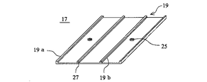
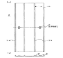
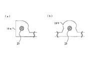
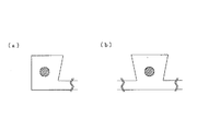
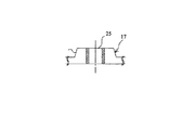
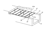
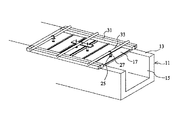
図1はこの発明の側溝床版用残存型枠の1実施例を示す残存型枠板の斜視図、図2(a)はその平面図、(b)はその側面図、図3(a)は残存型枠板の板面に設けた第1のリブの拡大断面図、(b)は第2のリブの拡大断面図、図4(a)は残存型枠板の板面に設けた第1のリブの別の例を示す拡大断面図、(b)は第2のリブの別の例を示す拡大断面図、図5は治具取付孔を示す概略断面図、図6は残存型枠板を下部で支持する場合の設置状態を示す斜視図、図7は残存型枠板を上部から牽引する場合の設置状態を示す斜視図である。
Hereinafter, an embodiment of a residual formwork for a side groove floor slab according to the present invention will be described in detail with reference to the drawings.
FIG. 1 is a perspective view of a remaining mold plate showing one embodiment of a residual mold for a lateral groove floor of the present invention, FIG. 2 (a) is a plan view thereof, (b) is a side view thereof, and FIG. 3 (a). Is an enlarged cross-sectional view of the first rib provided on the plate surface of the remaining mold plate, FIG. 4B is an enlarged cross-sectional view of the second rib, and FIG. FIG. 5 is an enlarged cross-sectional view showing another example of the first rib, FIG. 5B is an enlarged cross-sectional view showing another example of the second rib, FIG. 5 is a schematic cross-sectional view showing the jig mounting hole, and FIG. FIG. 7 is a perspective view showing the installation state when the remaining mold plate is pulled from the upper part.
図1ないし図7にしたがってこの発明の側溝床版用残存型枠の一実施例について説明する。この実施例は、側溝用床版として大型の側溝の上に被せる床版を現場において製作する場合を例とする。11は側溝本体であり、この側溝本体11は例えば溝幅が700〜2500mm程度の大型のものが使用される(図6および図7参照)。
図1ないし図5において、13は側溝本体1の上方に左右対向して形成された床版搭載部である。また17は残存型枠板であり、この残存型枠板17は前記側溝本体11の前記床版搭載部13の上面に載置され、構築すべき側溝用床版としての床版21の下面に捨型枠材として使用されるものであり、この残存型枠板17は側溝本体11の開口部15を塞ぐようになっている。
An embodiment of the residual mold for a side groove floor slab according to the present invention will be described with reference to FIGS. In this embodiment, a case where a floor slab is placed on a large side groove as a side slab floor slab is manufactured as an example.
In FIG. 1 to FIG. 5,
前記残存型枠板17は、繊維補強レジンコンクリートにより予め工場において平面ほぼ矩形に形成される。残存型枠板17は、高い曲げ強度と剛性を有して床版21の下側部分を専有する大きさとし、かつコンクリートと密接に一体化するために、床版21に配筋される鉄筋を被覆して鉄筋の腐蝕防止やコンクリートの中性化を抑制し、しかもコンクリートCとの接合表面には、断面形状において上部が幅広の逆テーパ部を有する補強リブ19が複数本設けられている。
The
前記繊維補強レジンコンクリートに使用される繊維として好適なものは、ガラス繊維が使用されるほか、炭素繊維、金属繊維、合成繊維が使用される。 As a fiber suitable for the fiber-reinforced resin concrete, glass fiber is used, and carbon fiber, metal fiber, and synthetic fiber are used.
前記補強リブ19の大きさは、残存型枠板17の平面の大きさの大小に応じて自由に設定できる。なお図2(a),(b)において、補強リブ19は残存型枠板2の上面に4本形成され、このうち2本の補強リブ19aは残存型枠板17の左右端に形成され、且つ残りの2本の補強リブ19aが内方に適宜の間隔をあけて外側の前記補強リブ19aに対して平行に形成される。
The size of the reinforcing
そして図3(a)、(b)に示すように、第1の補強リブ19aは、外側端面を垂直に、また内側端面をくの字状に形成され、かつ上部は面取りされている。
また図4(a)、(b)に示すように、第2の補強リブ19bは、両側端面をくの字状に形成され、かつ上部は面取りされて円弧状断面に形成されている。
いずれにしても断面形状において上部が幅広の逆テーパ部20を有しており、打設したコンクリートがこの逆テーパ部20に係合して残存型枠板17に強固に密着するようになっている。
As shown in FIGS. 3A and 3B, the first reinforcing rib 19a is formed such that the outer end face is vertical, the inner end face is formed in a dogleg shape, and the upper part is chamfered.
Further, as shown in FIGS. 4A and 4B, the second reinforcing rib 19b is formed in a dogleg shape on both side end surfaces, and the upper portion is chamfered to form an arc-shaped cross section.
In any case, the cross-sectional shape has a reverse taper portion 20 whose upper portion is wide, and the placed concrete engages with the reverse taper portion 20 and comes into close contact with the remaining
23は前記補強リブ19内に挿入される補強部材としての補強筋であり、この補強筋23は前記補強リブ19の強度を一層強く確保するためのものであり、例えば外径が約6〜12mm程度のFRP製棒状材が使用される。そして図示においては補強筋23は1本が挿入されているが、複数本であってもよい。しかも補強リブ19は、残存型枠板17が単なる板状のほぼ同一厚さのものに比べて荷重に対する高い曲げ剛性を増し、上面に打設されるコンクリートの水平剪断力に対する耐力をもたせ、剛性を高める機能をも備えている。
残存型枠板17は、その適所に治具取付孔25等からなる連結部が形成されている。そしてこの治具取付孔25には残存型枠板17を下から支持する支持ボルト27をネジ付けたり、残存型枠板17を上から支持する吊下げボルト29をネジ付けることができるようになっている。
The
コンクリート25は図6のように、下から治具取付孔25に取り付けた支持ボルト27で支持された残存型枠板17の上方に、例えば路面と一体的に打設される。
また残存型枠板17の幅方向の両側に側枠31を設置し、その上部に横桁33を介して吊下げボルト29を吊下げ、治具取付孔25に取り付けた吊下げボルト29で牽引した残存型枠板17上にコンクリート25が打設される。
このコンクリートが養生、固化された後に残存型枠板17と一体化した側溝用床版21が現場において形成される。
As shown in FIG. 6, the
Further,
After this concrete is cured and solidified, a side gutter floor slab 21 integrated with the
この際、残存型枠板17はコンクリートパネルとは異なり、繊維補強レジンコンクリート等により形成されているので、軽量であり、剛性は高くなる。
At this time, unlike the concrete panel, the
この発明は、上記側溝本体の上面に形成した床版搭載部内に載置可能に収容される蓋体のみならず、また橋梁の桁間に掛渡される床板、建物のスラブ等にも使用することが可能である。 The present invention is used not only for a lid that can be placed in a floor slab mounting portion formed on the upper surface of the gutter body, but also for a floor board spanned between bridge girders, a building slab, and the like. Is possible.
11 側溝本体
13 床版搭載部
15 開口部
17 残存型枠板
19,19a,19b 補強リブ
20 逆テーパ部
21 床版
23 補強筋
25 治具取付孔
27 支持ボルト
29 吊下げボルト
31 側枠
33 横桁
11 Side groove
Claims (6)
6. The residual mold for a side groove floor slab according to claim 5, wherein the connecting portion of the residual mold plate is a jig mounting hole.
Priority Applications (1)
| Application Number | Priority Date | Filing Date | Title |
|---|---|---|---|
| JP2004121129A JP2005299344A (en) | 2004-04-16 | 2004-04-16 | Remaining form for side ditch floor slab |
Applications Claiming Priority (1)
| Application Number | Priority Date | Filing Date | Title |
|---|---|---|---|
| JP2004121129A JP2005299344A (en) | 2004-04-16 | 2004-04-16 | Remaining form for side ditch floor slab |
Publications (1)
| Publication Number | Publication Date |
|---|---|
| JP2005299344A true JP2005299344A (en) | 2005-10-27 |
Family
ID=35331224
Family Applications (1)
| Application Number | Title | Priority Date | Filing Date |
|---|---|---|---|
| JP2004121129A Pending JP2005299344A (en) | 2004-04-16 | 2004-04-16 | Remaining form for side ditch floor slab |
Country Status (1)
| Country | Link |
|---|---|
| JP (1) | JP2005299344A (en) |
Cited By (3)
| Publication number | Priority date | Publication date | Assignee | Title |
|---|---|---|---|---|
| CN102888957A (en) * | 2012-08-15 | 2013-01-23 | 杨众 | Prefabricated light slab stair |
| JP2019052507A (en) * | 2017-09-19 | 2019-04-04 | 株式会社大林組 | Concrete buried formwork and integration method of concrete buried formwork and post-cast concrete |
| CN116043666A (en) * | 2022-12-13 | 2023-05-02 | 海洋石油工程股份有限公司 | Steel Fiber Concrete-GFRP Composite Slab Composite Beam and Its Construction Method |
-
2004
- 2004-04-16 JP JP2004121129A patent/JP2005299344A/en active Pending
Cited By (4)
| Publication number | Priority date | Publication date | Assignee | Title |
|---|---|---|---|---|
| CN102888957A (en) * | 2012-08-15 | 2013-01-23 | 杨众 | Prefabricated light slab stair |
| JP2019052507A (en) * | 2017-09-19 | 2019-04-04 | 株式会社大林組 | Concrete buried formwork and integration method of concrete buried formwork and post-cast concrete |
| JP7034433B2 (en) | 2017-09-19 | 2022-03-14 | 株式会社大林組 | How to integrate concrete buried formwork and concrete buried formwork with post-casting concrete |
| CN116043666A (en) * | 2022-12-13 | 2023-05-02 | 海洋石油工程股份有限公司 | Steel Fiber Concrete-GFRP Composite Slab Composite Beam and Its Construction Method |
Similar Documents
| Publication | Publication Date | Title |
|---|---|---|
| WO2008133460A1 (en) | Composite concrete column and construction method using the same | |
| KR100854224B1 (en) | Half section precast cantilever deck and construction method | |
| KR100812132B1 (en) | Concrete slab assembly | |
| KR101186053B1 (en) | Method of Constructing Insitu Concrete Beam Using Preinstalled Precast Concrete Slab | |
| JP4028831B2 (en) | Removable support beam | |
| KR20170014821A (en) | Cable-Stayed Bridge having Precast Core, and Constructing Method thereof | |
| KR102000534B1 (en) | Construction method using textile reinforcing panel of high durability for combined usage of permanent form | |
| KR101482523B1 (en) | Nodular Box Girder, and Nodular Box Girder Bridge and Constructing Method thereof | |
| JP2014109152A (en) | Beam member and floor structure | |
| KR101389044B1 (en) | Steel girders for bridges and its production method | |
| JP4073746B2 (en) | Construction method of corrugated steel web bridge | |
| JPH04228710A (en) | Road slab for bridge | |
| JP6517121B2 (en) | Buried formwork | |
| KR100728106B1 (en) | Cantilevered part installation structure and construction method of bridge deck | |
| KR100462966B1 (en) | Prestressed Concrete U-Girder of compositive girder bridge | |
| JP2002339496A (en) | Slab construction method and ceiling construction method | |
| KR20070107495A (en) | Formwork assembly and building construction method using same | |
| JP2006169730A (en) | Concrete bridge girder and method of forming the same | |
| JPH0913486A (en) | Concrete structure body | |
| JPH10110498A (en) | Half precast slab and method of constructing hollow flat slab using the same | |
| KR100650444B1 (en) | Construction method of cantilevered part of bridge | |
| JPH04333705A (en) | Fibre-reinforced resin permanent formwork for concrete floor slab and construction thereof and frp-reinforced concrete slab | |
| KR20220011044A (en) | the device fixing bar in detachable form and the detachable form structure using the same | |
| KR100588350B1 (en) | Method of constructing the side end of median side of bridge slab and upper bracket applied to it | |
| KR20050112913A (en) | A construction system of the wall/dome and the the method thereof it |
Legal Events
| Date | Code | Title | Description |
|---|---|---|---|
| A621 | Written request for application examination |
Free format text: JAPANESE INTERMEDIATE CODE: A621 Effective date: 20070413 |
|
| A977 | Report on retrieval |
Free format text: JAPANESE INTERMEDIATE CODE: A971007 Effective date: 20090306 |
|
| A131 | Notification of reasons for refusal |
Free format text: JAPANESE INTERMEDIATE CODE: A131 Effective date: 20090716 |
|
| A521 | Written amendment |
Free format text: JAPANESE INTERMEDIATE CODE: A523 Effective date: 20090817 |
|
| A02 | Decision of refusal |
Free format text: JAPANESE INTERMEDIATE CODE: A02 Effective date: 20091104 |