JP2005299330A - Dozer for shovel - Google Patents
Dozer for shovel Download PDFInfo
- Publication number
- JP2005299330A JP2005299330A JP2004120588A JP2004120588A JP2005299330A JP 2005299330 A JP2005299330 A JP 2005299330A JP 2004120588 A JP2004120588 A JP 2004120588A JP 2004120588 A JP2004120588 A JP 2004120588A JP 2005299330 A JP2005299330 A JP 2005299330A
- Authority
- JP
- Japan
- Prior art keywords
- force
- blade
- dozer
- soil
- discharge
- Prior art date
- Legal status (The legal status is an assumption and is not a legal conclusion. Google has not performed a legal analysis and makes no representation as to the accuracy of the status listed.)
- Pending
Links
- 239000002689 soil Substances 0.000 claims abstract description 67
- 238000003825 pressing Methods 0.000 claims abstract description 15
- 230000007423 decrease Effects 0.000 claims description 9
- 238000004364 calculation method Methods 0.000 description 6
- 238000007599 discharging Methods 0.000 description 3
- 238000009412 basement excavation Methods 0.000 description 2
- 238000004140 cleaning Methods 0.000 description 2
- 238000007689 inspection Methods 0.000 description 2
- 238000004519 manufacturing process Methods 0.000 description 2
- 230000000052 comparative effect Effects 0.000 description 1
- 230000008602 contraction Effects 0.000 description 1
- 238000010586 diagram Methods 0.000 description 1
- 238000009826 distribution Methods 0.000 description 1
- 230000000694 effects Effects 0.000 description 1
- 230000002452 interceptive effect Effects 0.000 description 1
- 238000010408 sweeping Methods 0.000 description 1
- 230000007704 transition Effects 0.000 description 1
Images
Classifications
-
- E—FIXED CONSTRUCTIONS
- E02—HYDRAULIC ENGINEERING; FOUNDATIONS; SOIL SHIFTING
- E02F—DREDGING; SOIL-SHIFTING
- E02F3/00—Dredgers; Soil-shifting machines
- E02F3/04—Dredgers; Soil-shifting machines mechanically-driven
- E02F3/76—Graders, bulldozers, or the like with scraper plates or ploughshare-like elements; Levelling scarifying devices
- E02F3/7609—Scraper blade mounted forwardly of the tractor on a pair of pivoting arms which are linked to the sides of the tractor, e.g. bulldozers
Landscapes
- Engineering & Computer Science (AREA)
- Mechanical Engineering (AREA)
- Mining & Mineral Resources (AREA)
- Civil Engineering (AREA)
- General Engineering & Computer Science (AREA)
- Structural Engineering (AREA)
- Operation Control Of Excavators (AREA)
- Cleaning In General (AREA)
- Control Of Motors That Do Not Use Commutators (AREA)
- Conveying And Assembling Of Building Elements In Situ (AREA)
- Paper (AREA)
- Shovels (AREA)
Abstract
Description
本発明はショベルの下部走行体に装着されて排土作業を行なうドーザに関するものである。 The present invention relates to a dozer that is mounted on a lower traveling body of an excavator and performs a soil discharging operation.
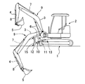
図6にドーザ付きの小型ショベル(ミニショベルと称される)を示す。 FIG. 6 shows a small excavator with a dozer (referred to as a mini excavator).
このショベルは、基本的には、クローラ式の下部走行体1上に上部旋回体2が縦軸まわりに旋回自在に搭載され、この上部旋回体2に、ブーム3、アーム4、バケット5及びこれらを駆動する油圧シリンダ(ブーム、アーム、バケット各シリンダ)6,7,8から成る作業(掘削)アタッチメント9が装着されて構成される。
In this excavator, an
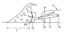
ドーザ10は、図7にも示すように、ドーザアーム11と、このドーザアーム11の先端に地面に対してすくい角θを持つ状態で取付けられたブレード(排土板)12とを備え、ドーザアーム11の基端部が下部走行体1に水平なアーム支軸13によって取付けられる。
As shown in FIG. 7, the
また、ドーザアーム11と下部走行体1との間にドーザシリンダ14が設けられ、同シリンダ14の伸縮作動によりドーザアーム11がアーム支軸13を中心に回動してブレード12が上下に移動する。
Further, a
排土作業を行なうときは、図示のようにブレード12の下端を接地させた状態で下部走行体1を走行させることにより、図7の矢印aで示す押し込み力によってブレード12の前面(ブレード面)15で土を削り、排土する。
When performing the earth removal work, the lower traveling body 1 is run with the lower end of the
この排土作用は、次のようにして行なわれる。 This soil removal action is performed as follows.
(イ)削った土がブレード面15の前方に溜まり始める。
(A) The shaved soil begins to accumulate in front of the
(ロ)溜まった土が、ブレード面15に沿って上昇する。
(B) The accumulated soil rises along the
(ハ) 押し上げられた土は、自重及び押し上げ力により前方に崩れていく。 (C) The pushed up soil collapses forward due to its own weight and pushing force.
(二) 崩れた土は、ブレード中心を境に左右から排出される。 (2) The broken soil is discharged from the left and right sides of the blade center.
この場合、上記(ハ)の段階で、図7の矢印bで示すようにブレード上方に盛り上がった土がブレード上面を乗り越えて後方にこぼれ落ちると、仕上げ面が荒らされるため、これを避けるためにブレード12を一旦上げて土山上部を前方に掃き出し、あるいはバックして整地し直す等の余分な処理が必要となり、作業効率が大幅に低下する。
In this case, in the above stage (c), when the soil that has risen above the blade climbs over the blade upper surface and spills backward as shown by the arrow b in FIG. 7, the finished surface is roughened. Excessive processing such as raising the
従って、ドーザ作業においては、作業効率を高める上で、この土のブレード後方への乗り越え量をできるだけ少なくすることが肝要となる。 Therefore, in the dozer work, it is important to reduce the amount of the soil that can be moved over to the rear of the blade as much as possible in order to improve the work efficiency.
この乗り越え量を減少させる策として、第1に、ブレード幅に対してブレード高さを十分大きくとることが考えられる。 As a measure for reducing the amount of overcoming, first, it is conceivable to make the blade height sufficiently larger than the blade width.
ところが、ショベルのドーザ10においては、特有の問題点として、図6に示すようにドーザ10が作業アタッチメント9の下方に位置し、しかも作業アタッチメント9は図中二点鎖線で示すように掘削時にかなり下方まで下がるため、ドーザ10と干渉するおそれがある。
However, in the
このため、ブレード高さを十分大きくとることができず、この結果、土の乗り越えが起こり易い状況にあった。 For this reason, the blade height could not be made sufficiently large, and as a result, it was in a situation where it was easy for the soil to get over.
そこで、従来のドーザ10においては、図7,8に示すようにブレード面15の上部を前方に大きくオーバーハングする形で湾曲させることにより、下向きの押し付け力Fd(図8参照)を発生させて乗り越えを回避することとしている。
Therefore, in the
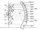
図8は、ブレード面15を高さ方向に複数(NO1〜NO10)の区域に分け、各区域を近似の直線に置き換えて力の発生状況を表したもので、Fuは土をブレード面15に沿って押し上げる押し上げ力、Fdは土を下向きに押し付ける押し付け力である。
FIG. 8 shows the state of force generation by dividing the
同図に示すように、ブレード面15の下端から中間部までの区域(NO1〜NO4。ブレード面下部)15aで押し上げ力Fuが作用する一方、中間部から上部までの区域(NO5〜NO10。ブレード面上部15bでは押し付け力Fdが作用し、押し付け力Fdの総和ΣFdが押し上げ力Fuの総和ΣFuとほぼ等しくなる(ΣFu>ΣFdではあるが、その比率が50:50に近い値となる)ようにブレード面15の形状が設定されている(この点は本発明の実施形態との比較において詳述する)。
As shown in the figure, the pushing force Fu acts in the area from the lower end of the
しかし、こうすると、押し上げ力Fuが押し付け力Fdによってほとんど打ち消される結果、ブレード面上部で最終的に残存する実質押し上げ力が小さくなるため、土が前方に回らずに堆積して図7に示すように裾Lの長い土山が形成される。このため、ブレード12の前進力により山が後方に崩れ易くなる。
However, in this case, the pushing force Fu is almost canceled by the pushing force Fd, so that the substantial pushing force finally remaining at the upper part of the blade surface becomes small, so that the soil accumulates without rotating forward as shown in FIG. An earthen mountain with a long skirt L is formed. For this reason, the mountain tends to collapse backward due to the forward force of the
また、本発明者の試験によると、実際には、ブレード面15に土が当たることによるエネルギーロスがあり、これが押し上げ力Fuを減少させる原因の一つになることが解明されている。
Further, according to the test by the present inventor, it has been clarified that there is actually an energy loss due to the soil hitting the
よって、前記のようにブレード面上部での押し上げ力Fuの残存値が小さい従来のドーザ10によると、土の乗り越えが発生し易く、作業効率が低いものとなっていた。
Therefore, according to the
そこで本発明は、押し上げた土を前方に効率良く回して後方への乗り越えを抑え、ドーザ作業の効率を高めることができるショベルのドーザを提供するものである。 Accordingly, the present invention provides an excavator dozer that can efficiently rotate the pushed-up soil forward to suppress overcoming behind and increase the efficiency of the dozer operation.
請求項1の発明は、下部走行体にドーザアームを介してブレードが地面に対してすくい角をもって取付けられ、このブレードを接地させた状態で上記下部走行体を走行させることにより、ブレード面で排土作業を行なうショベルのドーザにおいて、上記ブレード面が次の要件を満足する形状に設定されたものである。 According to the first aspect of the present invention, the blade is attached to the lower traveling body via the dozer arm with a rake angle, and the lower traveling body is traveled in a state where the blade is grounded, so that the earth is discharged on the blade surface. In the excavator dozer that performs the work, the blade surface is set to a shape that satisfies the following requirements.
A) 土をブレード面に沿って押し上げる押し上げ力Fuを発生させること。 A) Generate a lifting force Fu that pushes up the soil along the blade surface.
B) 上部に放出面を有し、この放出面で上記押し上げ力Fuが、押し上げた土を前方に回す前方上向きの放出力を発生させること。 B) It has a discharge surface at the top, and the above-mentioned lifting force Fu generates a forward upward discharge force that rotates the pushed-up soil forward.
C) 上記放出面において放出力を発生させることによって生じる下向きの押し付け力Fdの総和ΣFdと、上記押し上げ力の総和ΣFuとの関係が、
ΣFu>ΣFd
となること。
C) The relationship between the sum ΣFd of the downward pressing force Fd generated by generating the discharge force on the discharge surface and the sum ΣFu of the pushing force is
ΣFu> ΣFd
To be.
D) 上記押し上げ力Fuをプラス値とし、放出面に土が当たることによって生じる押し上げ力の減少分と、押し付け力Fdとをマイナス値として、放出面の最終部分での値がプラスとなること。 D) The push-up force Fu is a positive value, the decrease in the push-up force caused by the soil hitting the discharge surface and the push force Fd are negative values, and the value at the final part of the discharge surface is positive.
請求項2の発明は、請求項1の構成において、押し上げ力の総和ΣFuと押し付け力Fdの総和ΣFdの比率がほぼ8:2となるようにブレード面の形状が設定されたものである。 According to a second aspect of the present invention, in the configuration of the first aspect, the shape of the blade surface is set such that the ratio of the total sum ΣFu of the pushing force and the total sum ΣFd of the pressing force Fd is approximately 8: 2.
請求項3の発明は、請求項1または2の構成において、ブレード面が、曲率の異なる複数の曲面が連続する面として形成されたものである。 According to a third aspect of the present invention, in the configuration of the first or second aspect, the blade surface is formed as a surface in which a plurality of curved surfaces having different curvatures are continuous.
請求項4の発明は、請求項1乃至3のいずれかの構成において、ブレードが、下部走行体に対するドーザアームの取付点を中心として上下方向に移動可能に設けられ、上記ドーザアームの取付点の高さ位置が、ブレード接地状態で放出面の高さ範囲内に設定されたものである。 According to a fourth aspect of the present invention, in the configuration according to any one of the first to third aspects, the blade is provided so as to be movable in the vertical direction around the attachment point of the dozer arm with respect to the lower traveling body, and the height of the attachment point of the dozer arm. The position is set within the height range of the discharge surface in the blade grounded state.
請求項5の発明は、請求項1乃至4のいずれかの構成において、ブレード面の高さ寸法Hと幅寸法Wとが、
W=4.4〜5.7×H
の関係に設定されたものである。
The invention according to
W = 4.4-5.7 × H
It is set in the relationship.
請求項6の発明は、請求項1乃至5のいずれかの構成において、ブレードが下部走行体の進行方向と直交して設けられたものである。 A sixth aspect of the present invention is the structure according to any one of the first to fifth aspects, wherein the blade is provided perpendicular to the traveling direction of the lower traveling body.
ドーザ作業時の土の挙動は、前に述べたようにブレード面によって土が受ける力の方向と大きさで決まる。すなわち、削られた土は、押し上げ力によりブレード面に沿って上昇し、押し付け力によって下降しようとする。 The behavior of the soil during the dozer operation is determined by the direction and magnitude of the force applied to the soil by the blade surface as described above. That is, the shaved soil rises along the blade surface by the pushing force and tends to descend by the pushing force.
ここで、押し上げ力を前向きに転換させることによって、土を前方に回そうとする力(放出力)が発生し、この放出力が十分に大きいと、土が効率良く前方に回される。 Here, by changing the push-up force forward, a force (discharge force) for turning the soil forward is generated. When the discharge force is sufficiently large, the soil is efficiently rotated forward.
本発明によると、ブレード上部の放出面で押し上げ力Fuの方向を前向きに転換させて放出力を発生させ、
(i) この放出力の源である押上げ力の総和ΣFuが、押し付け力Fdの総和ΣFdよりも大きくなり、
(ii) 押し上げ力Fuをプラス値とし、放出面に土が当たることによって生じる押し上げ力の減少分と、押し付け力Fdとをマイナス値として、放出面の最終部分での値がプラスとなる
ようにブレード面の形状を設定したから、放出力を十分大きくとることができる。
According to the present invention, the direction of the push-up force Fu is changed forward on the discharge surface at the top of the blade to generate a discharge power,
(i) The total sum ΣFu of the push-up force that is the source of the discharge power is larger than the total sum ΣFd of the push-in force Fd,
(ii) The pushing force Fu is set to a positive value, and the decrease in the pushing force caused by the soil hitting the discharge surface and the pressing force Fd are set to a negative value so that the value at the final part of the discharge surface is positive. Since the shape of the blade surface is set, the discharge power can be made sufficiently large.
これにより、ブレード上部で土を高波のように効率良く前方に回して前に崩れ易い(裾の短い)土山を作り、左右から速やかに排出することができるため、排土作業の効率を高めることができる。 As a result, the soil can be turned forward efficiently like a high wave at the upper part of the blade to create a soil mountain that is easy to collapse forward (short hem) and discharged quickly from the left and right, increasing the efficiency of soil removal work Can do.
この場合、本発明者の計算によると、請求項2の発明のように、ΣFuとΣdの比率をほぼ8:2の比率とすることで上記(i)(ii)の要件を十分満足し、裾が短くて90°近くに立った土山を形成して、最も効率の良い排土作用を得ることができる。
In this case, according to the calculation of the present inventor, the requirement (i) (ii) is sufficiently satisfied by setting the ratio of ΣFu and Σd to be approximately 8: 2, as in the invention of
また、請求項3の発明によると、ブレード面をすべて曲面で形成したから、ブレード面に沿った土の移動がスムーズに行なわれ、直線の連続面とした場合のように変曲点で土がこびり付く等のおそれがなくなる。 In addition, according to the invention of claim 3, since the blade surface is entirely formed of a curved surface, the soil moves smoothly along the blade surface, and the soil is inflected at the inflection point as in the case of a straight continuous surface. There is no risk of sticking.
一方、請求項4の発明によると、ブレードの上下移動による放出面の角度変化が少なくてすむため、ブレードの上下移動にかかわらず効率の良い排土作用を確保することができる。
On the other hand, according to the invention of
ところで、ショベルのドーザの場合、作業アタッチメントとの干渉回避の観点からドーザ高さの上限値が決まるが、実機において上記の効率の良い排土作用を確保する上で、請求項5の発明のようにブレード面の高さ寸法Hと幅寸法Wとの関係を、
W=4.4〜5.7×H
に設定するのが望ましい。
By the way, in the case of an excavator dozer, the upper limit value of the dozer height is determined from the viewpoint of avoiding interference with the work attachment. However, in order to ensure the above-described efficient soil removal action in an actual machine, as in the invention of
W = 4.4-5.7 × H
It is desirable to set to.
なお、ブレード面幅Wが上記以下であると、下部走行体の幅よりも小さくなって排土効率が悪く、実用に適さない。また、上記以上に大きくすると、ブレード左右からの土の排出作用が悪くなり、上記ブレード面による作用が実質的に生かされない。 If the blade surface width W is equal to or smaller than the above, it is smaller than the width of the lower traveling body, the soil removal efficiency is poor, and is not suitable for practical use. Moreover, if it enlarges more than the above, the discharge | emission function of the soil from a blade right and left will worsen, and the effect | action by the said blade surface will not be utilized substantially.
一方、排土効率を上げる別の策として、ブレード全体を進行方向に対して平面視で傾斜して取付け、あるいはブレード全体を逆V字形とすることが考えられるが、こうすると、ショベルの足回りの点検や清掃等のためにブレードを支えにして機体を持ち上げたり、ブレードと作業アタッチメントとの間に物を挟んだりするショベルのドーザ特有の機能が果たせなくなる。 On the other hand, as another measure to increase the soil removal efficiency, it is conceivable that the entire blade is attached with an inclination in plan view with respect to the traveling direction, or the entire blade is formed in an inverted V shape. The special function of the excavator's dozer that lifts the airframe while supporting the blade for inspection or cleaning, or puts an object between the blade and the work attachment cannot be performed.
この点で、請求項6の発明のようにブレードを進行方向と直交して取付けるのが望ましい。また、こうしても、基本的に上記ブレード面の形状設定のみによって十分に効率の良い排土作用を確保することができる。 In this respect, it is desirable to mount the blade perpendicular to the traveling direction as in the invention of claim 6. Even in this case, a sufficiently efficient soil removal operation can be secured basically only by setting the shape of the blade surface.
図1,2に実施形態にかかるドーザのブレード21を示す。
1 and 2 show a
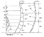
このブレード21の前面であるブレード面22は、曲率半径の異なる三つの曲面が高さ方向に連続する面として形成されている。
The
すなわち、最も大きな曲率半径R1を持った下部22aと、最も小さな曲率半径R2を持った中間部22bと、その中間の曲率半径R3を持った上部22cとによってブレード面22が形成されている。
That is, the
ここで、ブレード面下部22aは接地状態で後倒れに傾斜してすくい角θを形成する曲面、上部22cは前倒れに傾斜して土を前方に回す曲面としてそれぞれ形成されている。また、中間部22bは、下部22aから上部22cへ曲面を滑らかに移行させるつなぎの面として、後倒れの傾斜角度を徐々に小さくする曲面に形成されている。
Here, the blade surface
このブレード面22の形状は、次の作用が得られることを条件として設定されている。
The shape of the
I) 下端で削った土をブレード面22に沿って押し上げる押し上げ力Fuが発生すること。
I) A lifting force Fu that pushes up the soil cut at the lower end along the
II) 上部22cにおいて、押し上げ力Fuの方向が前向きに転換し、これによって土を前方に移動させる力(放出力)が発生すること。
II) In the
III) 上部(放出面)22cにおいて放出力を発生させることによって生じる下向きの押し付け力Fdの総和ΣFdと、上記押し上げ力FUの総和ΣFuとの関係が、
ΣFu>ΣFd
となること。
III) The relationship between the sum ΣFd of the downward pressing force Fd generated by generating the discharge force at the upper part (release surface) 22c and the sum ΣFu of the above-mentioned pushing force FU is as follows:
ΣFu> ΣFd
To be.
IV) 上記押し上げ力Fuをプラス値とし、放出面22cに土が当たることによって生じる押し上げ力の減少分と、押し付け力Fdとをマイナス値として、放出面の最終部分での値がプラスとなること。
IV) The push-up force Fu is a positive value, the decrease in push-up force caused by the soil hitting the
この点を図2,8及び表1〜3によってさらに詳述する。 This point will be described in more detail with reference to FIGS.
図2は、図8のブレード面15と同様に、ブレード面22を高さ方向に複数の区域(ここではNO1〜NO7の区域)に分け、かつ、各区域を近似直線に置き換えて力(分力)の発生状況を計算により求めたものである。
2, like the
条件: ブレード下端に単位荷重100を与えて、ブレード面22に荷重を加える。また、各区域の直線は、曲面であるブレード面22に対して寸法誤差が1mm以内とする。
Condition: A unit load of 100 is applied to the lower end of the blade, and a load is applied to the
ブレード面下部22aを形成するNO1〜NO3の各区域には、それぞれ65,50,50の大きさを持った後方上向きの押し上げ力Fuが発生する。
In each of the areas NO1 to NO3 forming the blade surface
ブレード面中間部22bを形成するNO4,5の区域にはそれぞれ30,10の大きさを持った後方上向きの押し上げ力Fuが発生する。
A rear upward push-up force Fu having a size of 30, 10 is generated in the NO4, 5 areas forming the blade surface
ブレード面上部(放出面)22cを形成するNO6,7の区域には、それぞれ15,30の大きさを持った後方下向きの押し付け力Fdが発生する(押し上げ力との対比から−を付して示す)。 In the areas of NO6 and 7 forming the blade surface upper part (release surface) 22c, rearward downward pressing force Fd having a size of 15,30 is generated (in contrast to the lifting force-). Show).
このような力が働くようにブレード面22の形状が設定されている。
The shape of the
これに対し、従来のドーザにおけるブレード面12の場合、図8及び表2に示すような力が発生する。ここでは、本発明の実施形態とほぼ同一サイズで、ブレード面全体が単一の曲面(たとえばR=160mm)で形成されたブレード面について、NO1〜NO10の10区域に発生する力を計算で求めている。
On the other hand, in the case of the
この従来例では、NO1〜NO4までの下部領域で押し上げ力Fu(NO1から順に50,55,40,15)が発生し、残りのNO5〜NO10の上部全領域で押し付け力(同、−5,−25,−45,−60,−70,−70)が発生する。 In this conventional example, the pushing force Fu (50, 55, 40, 15 in order from NO1) is generated in the lower region from NO1 to NO4, and the pushing force (-5, -25, -45, -60, -70, -70).
以上の結果、表3に示すように、押し上げ力Fuの総和ΣFuが、従来例では7810に対し本発明の実施形態では9525、押し付け力Fdの総和ΣFdが、従来例では−6755に対し本発明の実施形態では−2475となる。 As a result, as shown in Table 3, the total sum ΣFu of the lifting force Fu is 9525 in the embodiment of the present invention compared to 7810 in the conventional example, and the total sum ΣFd of the pressing force Fd is −6755 in the conventional example. In this embodiment, it is −2475.
つまり、従来例では、
ΣFu≒ΣFd(比率は54%:46%)
となるのに対し、本発明の実施形態によると、
ΣFu>ΣFd(比率は79%:21%)
となり、押し上げ力Fuの総和ΣFuが押し下げ力Fdの総和ΣFdを圧倒的に上回ることとなる。
In other words, in the conventional example,
ΣFu ≒ ΣFd (ratio is 54%: 46%)
In contrast, according to an embodiment of the present invention,
ΣFu> ΣFd (ratio is 79%: 21%)
Thus, the sum ΣFu of the push-up force Fu exceeds the sum ΣFd of the push-down force Fd overwhelmingly.
一方、本発明者の試験によると、放出面22cに土が当たることによるエネルギーロス分(放出抵抗)が押し上げ力Fuを減少させるため、実際には、放出面22cの最終部分(NO7の区域)で残存する押し上げ力は上記の値よりも低くなる。
On the other hand, according to the test of the present inventor, since the energy loss (release resistance) due to the soil hitting the
この実質押し上げ力を表1,2の最も右の欄に示す。表中、プラスは押し上げ力、マイナスは押し付け力及び放出抵抗による押し上げ力を減少させる力を示す。 The actual pushing force is shown in the rightmost column of Tables 1 and 2. In the table, plus indicates a pushing force, and minus indicates a pushing force and a force that decreases the pushing force due to the release resistance.
従来例から説明すると、図8及び表2において、NO1〜NO4の各区域(ブレード面下部15a)では放出抵抗は発生しないため、押し上げ力Fuのトータルは+7810となる。
If it demonstrates from a prior art example, in FIG. 8 and Table 2, since discharge resistance will not generate | occur | produce in each area (blade surface
これに対し、NO5〜NO10の各区域で押し付け力Fdに加えて放出抵抗が発生するため、その分、押し上げ力が減少する。この減少分を加味した実質押し上げ力の計算は、区域ごとに、放出抵抗による力の減少分の総和を求め、これと押し付け力の和を押し上げ力から差し引いて求める。 On the other hand, since the release resistance is generated in addition to the pressing force Fd in each of the areas NO5 to NO10, the pushing force is reduced accordingly. The calculation of the actual push-up force taking this decrease into account is obtained by calculating the sum of the decrease in force due to the release resistance for each area and subtracting the sum of this and the push force from the push-up force.
たとえばNO5の区域において、NO4の区域で働く押し上げ力が7810で、NO4,5での放出抵抗による力が29.99,30.00(単位荷重30)、力を受ける範囲が21、押し付け力が−105である場合に、
7810×(29.99/30.00)21−105
によってNO5での実質押し上げ力7650.512を求める。
For example, in the NO5 area, the pushing force working in the NO4 area is 7810, the release resistance force in NO4,5 is 29.99,30.00 (unit load 30), the force receiving range is 21, and the pushing force is -105,
7810 × (29.99 / 30.00) 21 −105
To obtain a substantially pushing force 7650.512 at NO5.
次に、この実質押し上げ力の数値7650.512をベースにNO6での実質押し上げ力を求め、以下、NO10まで同様の計算を行なう。 Next, based on the numerical value 7650.512 of the substantial pushing force, the substantial pushing force at NO6 is obtained, and thereafter, the same calculation is performed up to NO10.
この結果、ブレード面最終部分での実質押し上げ力は−2788.34、すなわち押し付け力の方が強くなる。これは、元々、押し上げ力Fuの総和ΣFuの絶対値が小さい(押し付け力Fdの総和ΣFdとの差が小さい)ことに起因する。 As a result, the actual pushing force at the final portion of the blade surface is -2788.34, that is, the pushing force is stronger. This is due to the fact that the absolute value of the sum ΣFu of the push-up force Fu is originally small (the difference from the sum ΣFd of the push-up force Fd is small).
従って、従来例によると、土がブレード高さを越える領域で押し上げ力が働かず、十分な放出力が得られないため、土が前方に回らずに堆積して図7に示すように裾Lの長い土山が形成され、前進力によって山が後方に崩れ易くなる。 Therefore, according to the conventional example, the push-up force does not work in the region where the soil exceeds the blade height, and sufficient discharge power cannot be obtained. Therefore, the soil accumulates without rotating forward, and the skirt L as shown in FIG. A long soil mountain is formed, and the mountain tends to collapse backward due to the forward force.
これに対し、本発明の実施形態によると、図2及び表1に示すように、上記同様の計算法によって各区域での実質押し上げ力を求めた結果、放出面22cの最終部分(NO7)での実質押し上げ力は+1159.429と十分大きいプラス値となる。
On the other hand, according to the embodiment of the present invention, as shown in FIG. 2 and Table 1, as a result of obtaining the substantial pushing force in each area by the same calculation method as described above, the final portion (NO7) of the
いいかえれば、本発明の実施形態では、押し上げ力Fuの総和ΣFuが押し付け力Fdの総和ΣFdよりも大きくなることに加えて、放出面22cの最終部分での値がプラスとなるとなるようにブレード面22の形状が設定されている。 In other words, in the embodiment of the present invention, in addition to the sum ΣFu of the pushing force Fu being larger than the sum ΣFd of the pushing force Fd, the blade surface has a positive value at the final portion of the discharge surface 22c. 22 shapes are set.
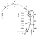
これにより、図1に示すように、土がブレード高さを越える領域においても、押し付け力Fdを上回る押し上げ力Fuが維持されるため、土が、十分大きな放出力Ffを加えられながら土の自重Gと粘性による高波のような放物線を描いてブレード前方に移動し、ブレード21から十分離れた位置で崩れ落ちる。
As a result, as shown in FIG. 1, even in the region where the soil exceeds the blade height, the pushing force Fu exceeding the pressing force Fd is maintained, so that the soil can be applied with a sufficiently large discharge force Ff while its own weight. It moves in front of the blade while drawing a parabola like a high wave due to G and viscosity, and collapses at a position sufficiently away from the
こうして、図3に示すように裾Lの短い土山が作られ、左右から速やかに排出されるため、排土作業の効率を高めることができる。 In this way, as shown in FIG. 3, a soil mound with a short skirt L is created and discharged quickly from the left and right, so the efficiency of the soil removal work can be increased.
この場合、表3中に示すように、ΣFuとΣdの比率を79:21(ほぼ8:2)の比率とすると、押し上げ力Fuの総和ΣFuが十分大きくて、実質押し上げ力も十分大きなプラス値となり、裾角度が90°近くになる裾Lの短いに近い土山が形成されて、最も効率の良い排土作用が得られることが明らかとなった。 In this case, as shown in Table 3, when the ratio of ΣFu and Σd is 79:21 (almost 8: 2), the sum ΣFu of the push-up force Fu is sufficiently large, and the substantial push-up force is a sufficiently large positive value. It has been clarified that the most efficient soil removal action can be obtained by forming a short earth crest having a short skirt L with a hem angle of 90 °.
なお、この好ましい比率は、土の粘度等の性状によって多少変動するが、ほぼ8:2の範囲となる。 This preferred ratio varies somewhat depending on properties such as the viscosity of the soil, but is in the range of about 8: 2.
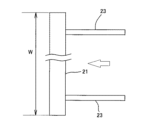
図3〜図5において、23はドーザアームで、このドーザアーム21の先端にブレード21が取付けられる点、ドーザアーム23の基端部が下部走行体1にアーム支軸24によって取付けられる点、及び図示しないドーザシリンダによりこのドーザアーム23がアーム支軸24を中心に回動してブレード21が上下移動する点は従来と同じである。
3 to 5,
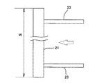
ここで、ブレード21は、図4に示すように矢印で示すドーザ進行方向に対して直交する状態で取付けられている。これにより、ショベルの足回りの点検や清掃等のためにブレード21を支えにして機体を持ち上げたり、ブレード21と作業アタッチメントとの間に物を挟んだりするショベルのドーザ特有の機能を確保することができる。
Here, as shown in FIG. 4, the
また、ブレード21の高さ寸法の上限値は、前記のように作業アタッチメントと干渉しない範囲として決まるが、実機において上記の効率の良い排土作用を確保する上で、ブレード面22の高さ寸法(下端から放出面22cの上端までの寸法)Hと、幅寸法W(図4中に示す)との関係を、
W=4.4〜5.7×H
に設定するのが望ましいことが計算によって確認された。
Further, the upper limit value of the height dimension of the
W = 4.4-5.7 × H
It was confirmed by calculation that it is desirable to set to.
なお、ブレード面幅Wが上記以下であると、下部走行体1の幅よりも小さくなって排土効率が悪く、実用に適さない。また、上記以上に大きくすると、ブレード左右からの土の排出作用が悪くなり、上記ブレード面22による排土作用が実質的に生かされない。
In addition, when the blade surface width W is equal to or smaller than the above, the width of the lower traveling body 1 is smaller than that of the lower traveling body 1, so that the soil removal efficiency is poor and is not suitable for practical use. Further, if it is made larger than the above, the soil discharging action from the left and right sides of the blade is deteriorated, and the soil discharging action by the
ところで、ドーザ作業においては、実際上、グラウンドレベルよりも上方での作業が主となるため、この点の作業性を重視する必要がある。 By the way, in the dozer work, the work above the ground level is actually the main, so it is necessary to emphasize the workability of this point.
従って、上記の効率の良い排土作業をグラウンドレベルよりも上方で確保するために、ブレード21を接地させた状態と上方に移動させた状態で、ブレード面上部(放出面)22cの角度変化ができるだけ小さくなるように考慮するのが望ましい。
Therefore, in order to ensure the above-described efficient earth removal work above the ground level, the angle change of the blade surface upper part (discharge surface) 22c changes between the state where the
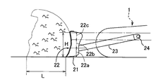
この実施形態では、上記観点から、図3及び図5(イ)に示すように、下部走行体1に対するドーザアーム23の取付点(アーム支軸24)の高さ位置が、ブレード接地状態でブレード面上部(放出面)22cの高さ範囲内に設定されている。
In this embodiment, from the above viewpoint, as shown in FIGS. 3 and 5 (a), the height position of the attachment point (arm support shaft 24) of the
こうすれば、ブレード21の上下移動による放出面22cの角度変化が小さくてすむため、ブレード21の上下移動にかかわらず効率の良い排土作用を確保することができる。
In this way, the angle change of the
比較例を挙げると、ブレード21を接地させた状態での理想的な放出面22cの角度αを16°とし、図3及び図5(イ)に示すようにドーザアーム取付点高さ位置を放出面22cの高さ範囲のほぼ中心部に設定した場合(前者)と、図5(ロ)に示すように放出面22cよりも下方のほぼ最下限位置に設定した場合(後者)とにおいて、ブレード21をある同じ高さまで上げたときの放出面22cの角度αが前者では26°、後者では29°となる。
As a comparative example, the angle α of the
つまり、前者では放出面角度αの角度変化が後者よりも約3°小さくなる。 That is, in the former, the change in the emission surface angle α is about 3 ° smaller than the latter.
放出角度αとは、ブレード面22の放出面22cの上端に対する接線と、ブレード接地状態での垂線とのなす角度をいう。
The discharge angle α is an angle formed by a tangent to the upper end of the
なお、ミニショベルの場合、地面よりも下方でのドーザ作業は、走行力が小さいこと等から数十mm程度までに制限されるため、放出面22cの角度変化は小さくて問題とならない。
In the case of a mini excavator, the dozer work below the ground is limited to about several tens of millimeters due to a small running force and the like, so the change in the angle of the
1 下部走行体
21 ブレード
22 ブレード面
22a ブレード面下部
22b ブレード面中間部
22c ブレード面上部(放出面)
23 ドーザアーム
24 アーム支軸(ドーザアームの取付点)
DESCRIPTION OF SYMBOLS 1
23
Claims (6)
A) 土をブレード面に沿って押し上げる押し上げ力Fuを発生させること。
B) 上部に放出面を有し、この放出面で上記押し上げ力Fuが、押し上げた土を前方に回す前方上向きの放出力を発生させること。
C) 上記放出面において放出力を発生させることによって生じる下向きの押し付け力Fdの総和ΣFdと、上記押し上げ力の総和ΣFuとの関係が、
ΣFu>ΣFd
となること。
D) 上記押し上げ力Fuをプラス値とし、放出面に土が当たることによって生じる押し上げ力の減少分と、押し付け力Fdとをマイナス値として、放出面の最終部分での値がプラスとなること。 In the excavator dozer, the blade is attached to the lower traveling body through the dozer arm with a rake angle with respect to the ground, and the lower traveling body is moved while the blade is in contact with the ground, thereby performing the earth removal work on the blade surface. An excavator dozer characterized in that the blade surface is set to a shape that satisfies the following requirements.
A) Generate a lifting force Fu that pushes up the soil along the blade surface.
B) Having a discharge surface in the upper part, and the above-mentioned push-up force Fu generates a forward upward discharge force that rotates the pushed-up soil forward.
C) The relationship between the sum ΣFd of the downward pressing force Fd generated by generating the discharge force on the discharge surface and the sum ΣFu of the pushing force is
ΣFu> ΣFd
To be.
D) The push-up force Fu is a positive value, the decrease in the push-up force caused by the soil hitting the discharge surface and the push force Fd are negative values, and the value at the final part of the discharge surface is positive.
W=4.4〜5.7×H
の関係に設定されたことを特徴とする請求項1乃至4のいずれか1項に記載のショベルのドーザ。 The height dimension H and width dimension W of the blade surface are
W = 4.4-5.7 × H
The shovel dozer according to any one of claims 1 to 4, characterized in that the relationship is set to
Priority Applications (6)
| Application Number | Priority Date | Filing Date | Title |
|---|---|---|---|
| JP2004120588A JP2005299330A (en) | 2004-04-15 | 2004-04-15 | Dozer for shovel |
| DE602005023931T DE602005023931D1 (en) | 2004-04-15 | 2005-04-12 | Excavator with planning unit |
| US11/103,548 US7048072B2 (en) | 2004-04-15 | 2005-04-12 | Excavator |
| EP05102879A EP1586711B1 (en) | 2004-04-15 | 2005-04-12 | Excavator with dozer unit |
| AT05102879T ATE483859T1 (en) | 2004-04-15 | 2005-04-12 | EXCAVATOR WITH PLANNING UNIT |
| CNB2005100652684A CN100371540C (en) | 2004-04-15 | 2005-04-15 | Bulldozer |
Applications Claiming Priority (1)
| Application Number | Priority Date | Filing Date | Title |
|---|---|---|---|
| JP2004120588A JP2005299330A (en) | 2004-04-15 | 2004-04-15 | Dozer for shovel |
Publications (1)
| Publication Number | Publication Date |
|---|---|
| JP2005299330A true JP2005299330A (en) | 2005-10-27 |
Family
ID=34939245
Family Applications (1)
| Application Number | Title | Priority Date | Filing Date |
|---|---|---|---|
| JP2004120588A Pending JP2005299330A (en) | 2004-04-15 | 2004-04-15 | Dozer for shovel |
Country Status (6)
| Country | Link |
|---|---|
| US (1) | US7048072B2 (en) |
| EP (1) | EP1586711B1 (en) |
| JP (1) | JP2005299330A (en) |
| CN (1) | CN100371540C (en) |
| AT (1) | ATE483859T1 (en) |
| DE (1) | DE602005023931D1 (en) |
Families Citing this family (4)
| Publication number | Priority date | Publication date | Assignee | Title |
|---|---|---|---|---|
| BE1019294A4 (en) * | 2010-04-16 | 2012-05-08 | Lille Allenbroer Leo Alix De | SURFACE MECHANISM AND MACHINE INCLUDING SUCH MECHANISM. |
| CN105484304B (en) * | 2014-09-16 | 2018-08-03 | 徐工集团工程机械股份有限公司 | A kind of spading system and the land leveller for including the spading system |
| US9945096B2 (en) | 2016-02-10 | 2018-04-17 | Deere & Company | Force-based work vehicle blade pitch control |
| CN106467421A (en) * | 2016-09-27 | 2017-03-01 | 机科发展科技股份有限公司 | Shovel mud plate turning machine |
Citations (5)
| Publication number | Priority date | Publication date | Assignee | Title |
|---|---|---|---|---|
| JPH04231523A (en) * | 1990-12-28 | 1992-08-20 | Iseki & Co Ltd | Ultra-compact excavator car soil removal device |
| JP2532631Y2 (en) * | 1991-11-08 | 1997-04-16 | 新キャタピラー三菱株式会社 | Blade device |
| JP2001040692A (en) * | 1999-07-30 | 2001-02-13 | Hitachi Constr Mach Co Ltd | Blade structure of construction machine for leveling work equipped with cutting edge with cross-shaped U-shape |
| JP2001049685A (en) * | 1999-08-05 | 2001-02-20 | Isao Kenmochi | Blade device for hydraulic shovel |
| JP2001355254A (en) * | 2000-06-14 | 2001-12-26 | Echigo Shoji Kk | Soil collecting body attached to soil discharging body installed on driving vehicle |
Family Cites Families (20)
| Publication number | Priority date | Publication date | Assignee | Title |
|---|---|---|---|---|
| US2169606A (en) * | 1936-02-15 | 1939-08-15 | Emsco Derrick & Equip Co | Bulldozer attachment for tractors |
| US3685592A (en) * | 1970-09-15 | 1972-08-22 | Case Co J I | Fluid cushioned dozer blade |
| US4019587A (en) * | 1976-05-17 | 1977-04-26 | Caterpillar Tractor Co. | Work vehicle having variable curvature blade assembly |
| FR2450913A1 (en) * | 1979-03-08 | 1980-10-03 | Takeuchi Manufacturing Cy Ltd | Rotating, back-acting mechanical bucket digger - has horizontally rotatable bucket digger and scraper blade |
| DE3039364A1 (en) * | 1980-10-18 | 1982-05-19 | Dr.Ing.H.C. F. Porsche Ag, 7000 Stuttgart | Recovery tank sweeping and support shield - has swivelling bottom piece hinged to top piece and fixable for sweeping |
| DE3043153A1 (en) * | 1980-11-15 | 1982-06-03 | Hanomag GmbH, 3000 Hannover | Earthmoving machine levelling shield cutter blade - is positioned on shield bottom, angled rearward from shield curve tangential plane |
| DE8528068U1 (en) * | 1985-10-02 | 1985-11-14 | Straus, Reinhold, 6950 Mosbach | Dozer with dozer blade, in particular for tracked vehicles |
| DE3644497A1 (en) * | 1986-12-24 | 1988-07-07 | Schaeff Karl Gmbh & Co | MULTIPURPOSE SIGN ON AN EXCAVATOR |
| US5018284A (en) * | 1987-03-31 | 1991-05-28 | Japan as represented by Director of Construction Machinery Works of Hokkaido Development Bureau | Snow plow for vehicles |
| CN2139596Y (en) * | 1992-12-01 | 1993-08-04 | 负建军 | Multifunctional bulldozer with adjustable ladle |
| DE59406556D1 (en) * | 1993-06-11 | 1998-09-03 | Zaugg Ag Eggiwil | SNOW PLOW |
| CA2109172C (en) * | 1993-10-25 | 2005-02-01 | 177197 Canada Ltee | Snow plow with deformable moldboard |
| US5950141A (en) * | 1996-02-07 | 1999-09-07 | Komatsu Ltd. | Dozing system for bulldozer |
| JP3378479B2 (en) * | 1997-09-19 | 2003-02-17 | 株式会社クボタ | Swivel truck frame |
| CN2318269Y (en) * | 1997-12-18 | 1999-05-12 | 张文明 | Bulldozer shovel with triangle cone |
| CN2375673Y (en) * | 1999-05-20 | 2000-04-26 | 王志文 | Wear-resisting bulldozer blade |
| JP2002322688A (en) * | 2001-04-25 | 2002-11-08 | Wakichi Kaneko | Water supply water antifreezing device |
| JP2002322668A (en) * | 2001-04-27 | 2002-11-08 | Hitachi Constr Mach Co Ltd | Turning construction machine and working method on slope by the same |
| CN2506701Y (en) * | 2001-05-18 | 2002-08-21 | 黄河工程机械集团有限责任公司 | Combined blade for bulldozer |
| JP4023392B2 (en) * | 2003-05-29 | 2007-12-19 | コベルコ建機株式会社 | Excavator with dozer |
-
2004
- 2004-04-15 JP JP2004120588A patent/JP2005299330A/en active Pending
-
2005
- 2005-04-12 US US11/103,548 patent/US7048072B2/en not_active Expired - Fee Related
- 2005-04-12 DE DE602005023931T patent/DE602005023931D1/en not_active Expired - Lifetime
- 2005-04-12 AT AT05102879T patent/ATE483859T1/en not_active IP Right Cessation
- 2005-04-12 EP EP05102879A patent/EP1586711B1/en not_active Expired - Lifetime
- 2005-04-15 CN CNB2005100652684A patent/CN100371540C/en not_active Expired - Fee Related
Patent Citations (5)
| Publication number | Priority date | Publication date | Assignee | Title |
|---|---|---|---|---|
| JPH04231523A (en) * | 1990-12-28 | 1992-08-20 | Iseki & Co Ltd | Ultra-compact excavator car soil removal device |
| JP2532631Y2 (en) * | 1991-11-08 | 1997-04-16 | 新キャタピラー三菱株式会社 | Blade device |
| JP2001040692A (en) * | 1999-07-30 | 2001-02-13 | Hitachi Constr Mach Co Ltd | Blade structure of construction machine for leveling work equipped with cutting edge with cross-shaped U-shape |
| JP2001049685A (en) * | 1999-08-05 | 2001-02-20 | Isao Kenmochi | Blade device for hydraulic shovel |
| JP2001355254A (en) * | 2000-06-14 | 2001-12-26 | Echigo Shoji Kk | Soil collecting body attached to soil discharging body installed on driving vehicle |
Also Published As
| Publication number | Publication date |
|---|---|
| CN1683721A (en) | 2005-10-19 |
| DE602005023931D1 (en) | 2010-11-18 |
| CN100371540C (en) | 2008-02-27 |
| ATE483859T1 (en) | 2010-10-15 |
| EP1586711B1 (en) | 2010-10-06 |
| EP1586711A2 (en) | 2005-10-19 |
| EP1586711A3 (en) | 2006-12-13 |
| US20050230129A1 (en) | 2005-10-20 |
| US7048072B2 (en) | 2006-05-23 |
Similar Documents
| Publication | Publication Date | Title |
|---|---|---|
| JP5566542B1 (en) | Excavation bucket and work vehicle | |
| CN1711399A (en) | Scrapers for working machines and construction and civil engineering machinery equipped with the same | |
| US9027663B2 (en) | Linkage arrangement | |
| JP2005299330A (en) | Dozer for shovel | |
| JP4689252B2 (en) | Work machine blade device and work machine equipped with the same blade device | |
| WO2007032191A1 (en) | Blade device for working machine and working machine mounted with the same | |
| JP2009162043A (en) | Road surface restoring apparatus | |
| CN209260793U (en) | A kind of bull-dozer with soil crushing device | |
| CN212926214U (en) | Push shovel | |
| CN101258290B (en) | Blade device for working machine and working machine mounted with the same | |
| CN208501766U (en) | Gutter one-pass molding bucket | |
| CN108487367B (en) | Cutter head for land leveler, bulldozer and snow plow | |
| CN211006808U (en) | Novel dozer blade | |
| CN214656723U (en) | Snow shoveling plate for snow shoveling machine | |
| CN218562422U (en) | Roadbed wide-step splicing rapid forming bucket | |
| CN210917545U (en) | An excavator bucket | |
| CN204139240U (en) | The flat tooth device of digger shovel | |
| CN212358405U (en) | Movable leveling device | |
| CN221298012U (en) | Bulldozer with adjustable angle | |
| CN204753670U (en) | Take grooving machine grab bucket and grooving machine of spiller | |
| CN207260214U (en) | A kind of bull-dozer with auxiliary dozer blade | |
| CN218200423U (en) | Anti-drifting device for middle groove of scraper conveyor | |
| CN211898630U (en) | Channel forming device | |
| CN210066861U (en) | Automatic adjust horizontal place of scraper bowl and level and use bull-dozer | |
| CN112836299A (en) | Method for optimizing overall stability of excavator |
Legal Events
| Date | Code | Title | Description |
|---|---|---|---|
| A621 | Written request for application examination |
Free format text: JAPANESE INTERMEDIATE CODE: A621 Effective date: 20061222 |
|
| A977 | Report on retrieval |
Free format text: JAPANESE INTERMEDIATE CODE: A971007 Effective date: 20090821 |
|
| A131 | Notification of reasons for refusal |
Free format text: JAPANESE INTERMEDIATE CODE: A131 Effective date: 20100406 |
|
| A521 | Request for written amendment filed |
Free format text: JAPANESE INTERMEDIATE CODE: A523 Effective date: 20100604 |
|
| A131 | Notification of reasons for refusal |
Free format text: JAPANESE INTERMEDIATE CODE: A131 Effective date: 20110222 |
|
| A02 | Decision of refusal |
Free format text: JAPANESE INTERMEDIATE CODE: A02 Effective date: 20110906 |