JP2005299324A - Waterproofing structure for roof tile - Google Patents
Waterproofing structure for roof tile Download PDFInfo
- Publication number
- JP2005299324A JP2005299324A JP2004120507A JP2004120507A JP2005299324A JP 2005299324 A JP2005299324 A JP 2005299324A JP 2004120507 A JP2004120507 A JP 2004120507A JP 2004120507 A JP2004120507 A JP 2004120507A JP 2005299324 A JP2005299324 A JP 2005299324A
- Authority
- JP
- Japan
- Prior art keywords
- roof tile
- roof
- water return
- flashing
- tile
- Prior art date
- Legal status (The legal status is an assumption and is not a legal conclusion. Google has not performed a legal analysis and makes no representation as to the accuracy of the status listed.)
- Pending
Links
- 238000004078 waterproofing Methods 0.000 title abstract 3
- XLYOFNOQVPJJNP-UHFFFAOYSA-N water Substances O XLYOFNOQVPJJNP-UHFFFAOYSA-N 0.000 claims description 63
- 238000010276 construction Methods 0.000 claims description 2
- 238000000465 moulding Methods 0.000 abstract 1
- 230000000994 depressogenic effect Effects 0.000 description 2
- 239000004927 clay Substances 0.000 description 1
- 230000007423 decrease Effects 0.000 description 1
- 239000012778 molding material Substances 0.000 description 1
Images

Landscapes
- Roof Covering Using Slabs Or Stiff Sheets (AREA)
Abstract
Description
本発明は、屋根瓦の表側縁部に水返しを形成した屋根瓦の防水構造に関するものである。 The present invention relates to a waterproof structure for a roof tile in which a water return is formed on the front side edge of the roof tile.
従来の一般的な屋根瓦の防水構造は、屋根瓦を施工したときに屋根瓦の重なり合う部分で下側になる屋根瓦の表側縁部に水返しを形成することで、屋根瓦の重なり合う部分の隙間に雨水が浸入しても、その雨水を水返しで塞き止めて雨水が屋根瓦の裏側(屋根の下地側)に浸入することを防止するようにしている。 The conventional waterproof structure for roof tiles is that the roof tile overlaps by forming a water return on the front edge of the roof tile that is the lower side of the roof tile overlap when the roof tile is installed. Even if rainwater enters the gap, the rainwater is blocked by returning water to prevent the rainwater from entering the back side of the roof tile (the roof base side).
しかし、台風等で雨や風が強いときには、屋根瓦の重なり合う部分の隙間に吹き込む雨水が水返しを越えて屋根瓦の裏側(屋根の下地側)まで浸入してしまうことがあり、十分な防水性を得ることができないという問題があった。 However, when rain and wind are strong due to typhoons, etc., rainwater blown into the gaps between the overlapping parts of the roof tiles may enter the back side of the roof tiles (the base side of the roof) beyond the water return. There was a problem that sex could not be obtained.
そこで、例えば、特許文献1(特開2000−54566号公報)に記載されているように、屋根瓦の裏面から水返しの先端部までの高さ寸法を高くすることで、水返しを高くして、防水性を高めるようにしたものがある。
しかし、上記特許文献1の防水構造では、屋根瓦の裏面から水返しの先端部までの高さ寸法を高くするため、次のような問題が発生する。 However, in the waterproof structure of the above-mentioned patent document 1, since the height dimension from the back surface of the roof tile to the tip of the water return is increased, the following problem occurs.
屋根瓦の裏面から水返しの先端部までの高さ寸法を高くすると、その分、屋根瓦を成形する成形型のうちの水返しを成形するキャビティの深さ寸法が深くなる。このため、屋根瓦を成形する際に、成形材料(粘土等)が水返しを成形するキャビティの先端部に到達しにくくなって、水返しを成形しにくくなる。 When the height dimension from the back surface of the roof tile to the tip of the water return is increased, the depth dimension of the cavity for forming the water return in the mold for forming the roof tile is increased accordingly. For this reason, when forming a roof tile, it becomes difficult for molding materials (clay etc.) to reach the front-end | tip part of the cavity which shape | molds a water return, and a water return becomes difficult to shape | mold.
また、一般に、工場等から屋根瓦を出荷する際には、屋根瓦を1列に重ね合わせて結束した状態でパレットに載せて運搬するようにしている。しかし、屋根瓦の裏面から水返しの先端部までの高さ寸法を高くすると、屋根瓦を1列に重ね合わせたときの寸法が大きくなるため、1枚の運搬用パレットに載せることができる屋根瓦の枚数が少なくなってしまい、屋根瓦の運搬コストが高くなってしまう。 In general, when shipping roof tiles from a factory or the like, the roof tiles are stacked and transported on a pallet in a bundled state. However, if the height from the back of the roof tile to the tip of the water return is increased, the size when the roof tiles are stacked in one row increases, so that the roof can be placed on one transport pallet. The number of tiles decreases, and the cost of transporting roof tiles increases.
本発明は、これらの事情を考慮してなされたものであり、従って本発明の目的は、水返しを高くして防水性を高めながら、成形性向上及び運搬コスト低減の要求を満たすことができる屋根瓦の防水構造を提供することにある。 The present invention has been made in consideration of these circumstances. Therefore, the object of the present invention is to satisfy the demands for improving the moldability and reducing the transportation cost while increasing the water return and improving the waterproof property. The object is to provide a waterproof structure for roof tiles.
上記目的を達成するために、本発明の請求項1に記載の屋根瓦の防水構造は、屋根瓦の表側縁部に水返しを形成したものにおいて、水返しに沿って屋根瓦の他の表面よりも窪んだ窪み部を形成したものである。この構造では、水返しに沿って窪み部を形成することで、水返し周辺の屋根瓦の表面を低くすることができるため、屋根瓦の裏面から水返し先端部までの高さ寸法を高くしなくても、水返し周辺の屋根瓦の表面(つまり窪み部の底面)に対して水返しの先端部を高くすることができ、防水性を向上させることができる。 In order to achieve the above object, the waterproof structure for a roof tile according to claim 1 of the present invention is such that a water return is formed on the front side edge of the roof tile, and the other surface of the roof tile along the water return. It forms a hollow part that is more recessed. In this structure, since the surface of the roof tile around the water return can be lowered by forming a recess along the water return, the height dimension from the back of the roof tile to the tip of the water return is increased. Even without this, the tip of the water return can be made higher with respect to the surface of the roof tile around the water return (that is, the bottom surface of the recess), and the waterproofness can be improved.
しかも、屋根瓦の裏面から水返し先端部までの高さ寸法を高くする場合に比べて、水返しを成形するキャビティの深さ寸法を浅くすることができるため、屋根瓦(水返し)の成形性を向上させることができる。また、屋根瓦の裏面から水返し先端部までの高さ寸法を高くせずに済むため、出荷時に屋根瓦を1列に重ね合わせたときの寸法を小さくすることができて、1枚の運搬用パレットに載せることができる屋根瓦の枚数を多くすることができ、屋根瓦の運搬コストを低減することができる。 Moreover, compared to the case where the height from the back of the roof tile to the tip of the water return is increased, the depth of the cavity for forming the water return can be reduced, so that the roof tile (water return) is formed. Can be improved. In addition, since it is not necessary to increase the height dimension from the back surface of the roof tile to the tip of the water return, the dimension when the roof tiles are stacked in one row at the time of shipment can be reduced, and one piece of transport is carried out. The number of roof tiles that can be placed on the pallet can be increased, and the transportation cost of the roof tile can be reduced.
この場合、請求項2のように、窪み部は、屋根瓦を施工したときに該窪み部の底面が該屋根瓦の中央方向に向かって下り傾斜となるように形成すると良い。このようにすれば、水返しで塞き止められた雨水が窪み部に流れ込んでも、その雨水を屋根瓦の中央方向に流すことができ、窪み部に雨水が溜まることを防止することができる。 In this case, as in claim 2, the recess is preferably formed such that when the roof tile is constructed, the bottom surface of the recess is inclined downward toward the center of the roof tile. If it does in this way, even if the rainwater blocked by the water return flows into the hollow part, the rainwater can be flowed toward the center of the roof tile, and the rainwater can be prevented from collecting in the hollow part.
また、請求項3のように、窪み部は、屋根瓦の右縁部又は左縁部に形成された水返しに沿って形成するようにすると良い。このようにすれば、屋根瓦を施工したときに屋根瓦の横方向で重なり合う部分の隙間に配置される水返しを高くすることができるため、屋根瓦の横方向で重なり合う部分の隙間の防水性を向上させることができる。 In addition, as described in claim 3, the recess is preferably formed along the water return formed on the right edge or the left edge of the roof tile. In this way, when the roof tiles are constructed, the water return placed in the gaps between the overlapping parts in the lateral direction of the roof tiles can be increased, so the waterproofness of the gaps in the overlapping parts in the lateral direction of the roof tiles can be increased. Can be improved.
また、請求項4のように、窪み部は、屋根瓦の上縁部に形成された水返しに沿って形成するようにしても良い。このようにすれば、屋根瓦を施工したときに屋根瓦の縦方向で重なり合う部分の隙間に配置される水返しを高くすることができるため、屋根瓦の縦方向で重なり合う部分の隙間の防水性を向上させることができる。 Moreover, you may make it form a hollow part along the water return formed in the upper edge part of a roof tile like Claim 4. In this way, when the roof tiles are constructed, the water return placed in the gaps between the overlapping parts in the vertical direction of the roof tiles can be increased, so the waterproofness of the gaps in the overlapping parts in the vertical direction of the roof tiles. Can be improved.
以下、本発明の一実施例を図面に基づいて説明する。
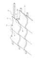
図4に示すように、屋根の桁行方向(屋根の傾斜方向と直角方向)に延びる瓦桟11が釘、ビス等により所定の間隔で固定され、この瓦桟11の上に、例えばJ形の屋根瓦12が、屋根の下部から上部に向かって順に取り付けられていると共に、屋根の左部から右部に向かって順に取り付けられている。
Hereinafter, an embodiment of the present invention will be described with reference to the drawings.
As shown in FIG. 4,
各屋根瓦12は、屋根瓦12の下側部がその下方に配置された屋根瓦12の上側部に重なり合うように配置されると共に、屋根瓦12の左側部がその左方に配置された屋根瓦12の右側部に重なり合うように配置され、その状態で屋根瓦12の上部に形成された固定用孔13に、通常は、釘、ビス等の止め金具14を挿通して打ち込むことで固定されている。尚、釘、ビス等の止め金具14で固定されていない場合もある。
Each
また、各屋根瓦12の右下側角部と左上側角部には、それぞれ切り欠き部15,16が形成され、各屋根瓦12の右下側角部の切り欠き部15が、その斜め下方に配置された屋根瓦12の左上側角部の切り欠き部16に係合支持されている。
In addition,
次に、図1乃至図3を用いて、屋根瓦12の防水構造について説明する。
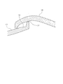
図1に示すように、各屋根瓦12の表側右縁部には、水返し17が上方に突出するように形成され、各屋根瓦12の表側上縁部には、水返し18が上方に突出するように形成されている。
Next, the waterproof structure of the
As shown in FIG. 1, a
図2に示すように、屋根瓦12を施工した際に、屋根瓦12の横方向で重なり合う部分では、下側になる屋根瓦12の表側右縁部に形成された水返し17が、上側になる屋根瓦12の左側部で覆われるようになっている。更に、屋根瓦12の表側右縁部に形成された水返し17に沿って窪み部19が屋根瓦12の他の表面よりも窪むように形成されている。これにより、水返し17周辺の屋根瓦12の表面を低くして、水返し17周辺の屋根瓦12の表面(つまり窪み部19の底面)に対して水返し17の先端部を高くするようにしている。また、この窪み部19は、屋根瓦12を施工したときに窪み部19の底面が屋根瓦12の中央方向に向かって下り傾斜となるように形成されている。
As shown in FIG. 2, when the
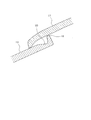
一方、図3に示すように、屋根瓦12を施工した際に、屋根瓦12の縦方向で重なり合う部分では、下側になる屋根瓦12の表側上縁部に形成された水返し18が、上側になる屋根瓦12の下側部で覆われるようになっている。更に、屋根瓦12の表側上縁部に形成された水返し18に沿って窪み部20が屋根瓦12の他の表面よりも窪むように形成されている。これにより、水返し18周辺の屋根瓦12の表面を低くして、水返し18周辺の屋根瓦12の表面(つまり窪み部20の底面)に対して水返し18の先端部を高くするようにしている。また、この窪み部20は、屋根瓦12を施工したときに窪み部20の底面が屋根瓦12の中央方向に向かって下り傾斜となるように形成されている。
On the other hand, as shown in FIG. 3, when the
以上説明した本実施例では、水返し17,18に沿って窪み部19,20を形成したので、水返し17,18周辺の屋根瓦12の表面を低くすることができて、水返し17,18周辺の屋根瓦12の表面(つまり窪み部19,20の底面)に対して水返し17,18の先端部を高くすることができ、防水性を向上させることができる。
In the present embodiment described above, since the
しかも、屋根瓦の裏面から水返し先端部までの高さ寸法を高くする場合に比べて、水返し17,18を成形するキャビティの深さ寸法を浅くすることができるため、屋根瓦12(水返し17,18)の成形性を向上させることができる。また、屋根瓦の裏面から水返し先端部までの高さ寸法を高くせずに済むため、出荷時に屋根瓦12を1列に重ね合わせたときの寸法を小さくすることができて、1枚の運搬用パレットに載せることができる屋根瓦12の枚数を多くすることができ、屋根瓦12の運搬コストを低減することができる。
Moreover, since the depth dimension of the cavity for forming the water return 17, 18 can be made shallower than when the height dimension from the back surface of the roof tile to the tip of the water return is increased, the roof tile 12 (water The moldability of the
また、本実施例では、屋根瓦12を施工したときに窪み部19,20の底面が屋根瓦12の中央方向に向かって下り傾斜となるようにしたので、水返し17,18で塞き止められた雨水が窪み部19,20に流れ込んでも、その雨水を屋根瓦12の中央方向に流すことができ、窪み部19,20に雨水が溜まることを防止することができる。
しかしながら、屋根瓦12を施工したときに窪み部19,20の底面が屋根瓦12の中央方向に向かって下り傾斜にならない構成としても良い。
Further, in this embodiment, when the
However, the construction may be such that when the
更に、本実施例では、屋根瓦12の右縁部にの水返し17に沿って窪み部19を形成すると共に、屋根瓦12の上縁部の水返し18に沿って窪み部20を形成するようにしたので、屋根瓦12を施工したときに屋根瓦12の横方向で重なり合う部分の隙間に配置される水返し17と屋根瓦12の縦方向で重なり合う部分の隙間に配置される水返し18の両方を高くすることができ、屋根瓦12の横方向で重なり合う部分の隙間と屋根瓦12の縦方向で重なり合う部分の隙間の両方の防水性を向上させることができる。
Furthermore, in the present embodiment, a
しかしながら、屋根瓦12の右縁部の水返し17と上縁部の水返し18のうちの一方だけに沿って窪み部を形成するようにしても良い。
また、屋根瓦12の左縁部に水返しを形成する場合には、屋根瓦12の左縁部の水返しに沿って窪み部を形成するようにしても良い。
However, you may make it form a hollow part along only one of the
In addition, when forming the water return on the left edge portion of the
その他、本発明は、水返しや窪み部の形状等を適宜変更しても良い等、要旨を逸脱しない範囲で種々変更して実施できる。 In addition, the present invention can be implemented with various changes without departing from the scope of the invention, such as changing the shape of the water return and the depression, etc.
12…屋根瓦、13…固定用孔、15,16…切り欠き部、17,18…水返し、19,20…窪み部 12 ... roof tile, 13 ... fixing hole, 15, 16 ... notch, 17, 18 ... water return, 19, 20 ... depression
Claims (4)
前記水返しに沿って前記屋根瓦の他の表面よりも窪んだ窪み部が形成されていることを特徴とする屋根瓦の防水構造。 In the waterproof structure of the roof tile that formed a water return on the front edge of the roof tile,
A waterproof structure for a roof tile, wherein a recess is formed along the water return that is recessed from the other surface of the roof tile.
Priority Applications (1)
| Application Number | Priority Date | Filing Date | Title |
|---|---|---|---|
| JP2004120507A JP2005299324A (en) | 2004-04-15 | 2004-04-15 | Waterproofing structure for roof tile |
Applications Claiming Priority (1)
| Application Number | Priority Date | Filing Date | Title |
|---|---|---|---|
| JP2004120507A JP2005299324A (en) | 2004-04-15 | 2004-04-15 | Waterproofing structure for roof tile |
Publications (1)
| Publication Number | Publication Date |
|---|---|
| JP2005299324A true JP2005299324A (en) | 2005-10-27 |
Family
ID=35331206
Family Applications (1)
| Application Number | Title | Priority Date | Filing Date |
|---|---|---|---|
| JP2004120507A Pending JP2005299324A (en) | 2004-04-15 | 2004-04-15 | Waterproofing structure for roof tile |
Country Status (1)
| Country | Link |
|---|---|
| JP (1) | JP2005299324A (en) |
-
2004
- 2004-04-15 JP JP2004120507A patent/JP2005299324A/en active Pending
Similar Documents
| Publication | Publication Date | Title |
|---|---|---|
| US6843032B2 (en) | Siding boards attachment structure and starter fitting | |
| JP2008285953A (en) | Wooden floor | |
| JP6326956B2 (en) | Solar panel float | |
| DK1739247T3 (en) | Insulation frame for a skylight | |
| JP2005299324A (en) | Waterproofing structure for roof tile | |
| JP2005299325A (en) | Waterproofing structure for roof tile | |
| JP5244349B2 (en) | Ventilated roof structure | |
| JP5993175B2 (en) | Ventilation cover | |
| JP4654159B2 (en) | Eaves tile | |
| JP5081196B2 (en) | Functional panel mounting structure on the roof | |
| JP4408791B2 (en) | Grating | |
| JP2005068882A (en) | Joint structure of exterior material | |
| JP6025100B2 (en) | Roof structure | |
| JP6410292B2 (en) | Ventilation structure | |
| JP2009127364A (en) | Soundproof panel | |
| JP2003278320A (en) | Roof tile | |
| JP2017128937A (en) | Waterproof tile | |
| JP5180666B2 (en) | ROOF MATERIAL AND ROOF MATERIAL CONVEYING METHOD | |
| JP6664097B2 (en) | Uneven roof material and connection structure of uneven roof material | |
| JP6425162B2 (en) | Connection structure of metal vertical facing material | |
| JP2010163758A (en) | Floor panel, unit for forming floor, and deck structure | |
| JP2006063708A (en) | Streak disaster prevention tile | |
| JP4997072B2 (en) | Girder insulation panel | |
| JP2007332561A (en) | Plain ridge tile | |
| JP2543275Y2 (en) | Mounting structure of ceramic outer wall material |
Legal Events
| Date | Code | Title | Description |
|---|---|---|---|
| A621 | Written request for application examination |
Free format text: JAPANESE INTERMEDIATE CODE: A621 Effective date: 20060810 |
|
| A977 | Report on retrieval |
Free format text: JAPANESE INTERMEDIATE CODE: A971007 Effective date: 20081107 |
|
| A131 | Notification of reasons for refusal |
Effective date: 20090730 Free format text: JAPANESE INTERMEDIATE CODE: A131 |
|
| A02 | Decision of refusal |
Effective date: 20091127 Free format text: JAPANESE INTERMEDIATE CODE: A02 |