JP2005299301A - Corrugated plate mounting structure and synthetic resin corrugated plate used for same - Google Patents

Corrugated plate mounting structure and synthetic resin corrugated plate used for same Download PDF

Info

Publication number
JP2005299301A
JP2005299301A JP2004119896A JP2004119896A JP2005299301A JP 2005299301 A JP2005299301 A JP 2005299301A JP 2004119896 A JP2004119896 A JP 2004119896A JP 2004119896 A JP2004119896 A JP 2004119896A JP 2005299301 A JP2005299301 A JP 2005299301A
Authority
JP
Japan
Prior art keywords
synthetic resin
corrugated plate
locking
resin corrugated
corrugated sheet
Prior art date
Legal status (The legal status is an assumption and is not a legal conclusion. Google has not performed a legal analysis and makes no representation as to the accuracy of the status listed.)
Pending
Application number
JP2004119896A
Other languages
Japanese (ja)
Inventor
Masahiro Iga
正浩 伊賀
Kazuhiro Fukuda
和宏 福田
Koji Yamada
浩二 山田
Kiyoshi Butani
潔 部谷
Current Assignee (The listed assignees may be inaccurate. Google has not performed a legal analysis and makes no representation or warranty as to the accuracy of the list.)
Takiron Co Ltd
Original Assignee
Takiron Co Ltd
Priority date (The priority date is an assumption and is not a legal conclusion. Google has not performed a legal analysis and makes no representation as to the accuracy of the date listed.)
Filing date
Publication date
Application filed by Takiron Co Ltd filed Critical Takiron Co Ltd
Priority to JP2004119896A priority Critical patent/JP2005299301A/en
Publication of JP2005299301A publication Critical patent/JP2005299301A/en
Pending legal-status Critical Current

Links

Images

Landscapes

  • Roof Covering Using Slabs Or Stiff Sheets (AREA)

Abstract

<P>PROBLEM TO BE SOLVED: To easily and accurately extend a synthetic resin corrugated plate between adjacent beam members juxtaposed with a fixed space, without nailing or bolt fastening in a mounting structure of the synthetic resin corrugated plate constituting a roof with daylighting performance of a simplified building or the like. <P>SOLUTION: Both side ends of the synthetic resin corrugated plate 1 are formed with locking ends 2, 2 bent downward, while the beam member 3 is provided with a fixing part 5 comprising an upward opened locking groove 6 and a bead 7 mounted on the upper face of the beam member 3. The opposed side faces of the adjacent beam members 3, 3 are integrally connected by several bar members 9, and while supporting the lower face of the synthetic resin corrugated plate 1 on the bar members 9, both side locking ends 2, 2 are inserted and locked in the locking grooves 6 of the beam members 3, 3. In this state, the beads 7 are mounted to the upper faces of the beam members 3 to fix both ends of the synthetic resin corrugated plate 1. <P>COPYRIGHT: (C)2006,JPO&NCIPI

Description

本発明は、簡易建物の屋根やバス停留所、カーポート、或いは、屋外通路上に設けられる採光性を有する屋根を構成するための合成樹脂製波板及びその取付構造に関するものである。   TECHNICAL FIELD The present invention relates to a synthetic resin corrugated plate and a mounting structure thereof for constituting a roof having a daylighting property provided on a roof of a simple building, a bus stop, a carport, or an outdoor passage.

合成樹脂製波板は軽量で取扱性に優れ、特に、ポリカーボネート樹脂よりなる波板は耐候性においても優れているので、屋外の簡易建物の屋根材として広く採用されている。この合成樹脂製波板によって屋根を構成するには、例えば、特許文献1に記載されているように、一定幅と長さを有する長方形状の波板において、幅方向に連続する山部と谷部との進行方向を母屋(横木)の長さ方向に向けた状態にして母屋の上面間に架設し、隣接する波板の対向端部における山部や谷部同士を順次重ね合わせることによって連続させると共にその重ね合わせ部と幅方向の中間部を波板の長さ方向に所定間隔毎に釘やボルトを母屋に打ち込むことによって固着している。   Synthetic resin corrugated sheets are lightweight and excellent in handling, and in particular, corrugated sheets made of polycarbonate resin are also excellent in weather resistance, and are therefore widely used as roofing materials for outdoor simple buildings. In order to form a roof with this synthetic resin corrugated sheet, for example, as described in Patent Document 1, in a rectangular corrugated sheet having a constant width and length, a peak and a valley that are continuous in the width direction. Continuing by laying between the upper surfaces of the purlins with the direction of travel with the section facing the length direction of the purlin (yoko), and sequentially stacking the peaks and valleys at the opposite ends of the adjacent corrugated plates At the same time, the overlapping portion and the intermediate portion in the width direction are fixed by driving nails and bolts into the purlin at predetermined intervals in the length direction of the corrugated sheet.

特開2001−132175号公報JP 2001-132175 A

しかしながら、上記のような合成樹脂製波板の取付構造によれば、合成樹脂製波板を釘やボルトによって母屋に固着しているために、合成樹脂製波板に設けられている多数の釘孔やボルト孔が弱体部となり、耐候性を有するにもかかわらず亀裂等の発生によって長期の使用に供することができなくなる虞れがあり、その上、これらの孔から雨水が浸入するので、雨漏りを防止するための処理を必要とする。また、多数の釘打ち或いはボルト止め作業を要するので、施工期間が長くなるばかりでなく、正確に釘打ち、ボルト止めを行うには熟練を要するといった問題点があった。   However, according to the synthetic resin corrugated plate mounting structure as described above, since the synthetic resin corrugated plate is fixed to the purlin with nails or bolts, a large number of nails provided on the synthetic resin corrugated plate are provided. Holes and bolt holes become weak parts and may not be able to be used for a long period of time due to the occurrence of cracks, etc. despite having weather resistance. Need to be processed to prevent Further, since a large number of nailing or bolting operations are required, not only the construction period is lengthened, but also there is a problem that skill is required for accurately nailing and bolting.

本発明はこのような問題点に鑑みてなされたもので、その目的とするところは、合成樹脂製波板の施工が釘着等によることなく簡単且つ正確に行うことができる波板の取付構造及びこれに使用する合成樹脂製波板を提供するにある。   The present invention has been made in view of such problems, and the object of the present invention is to provide a corrugated plate mounting structure in which the construction of a synthetic resin corrugated plate can be performed easily and accurately without using nailing or the like. And providing a synthetic resin corrugated sheet used therefor.

上記目的を達成するために、本発明の波板の取付構造は、請求項1に記載したように、幅方向に山部と谷部とを連続的に形成している合成樹脂製波板の両側端部を梁材に固定してなる波板の取付構造であって、合成樹脂製波板の両側端部に下方に向かって係止端部を屈折、形成している一方、上記梁材にその係止端部の固定部を設けてあり、この固定部に上記合成樹脂製波板の係止端部を係止させた状態で固定していることを特徴とする。   In order to achieve the above object, the corrugated sheet mounting structure according to the present invention is a corrugated sheet made of synthetic resin in which a crest and a trough are continuously formed in the width direction. A corrugated plate mounting structure in which both end portions are fixed to a beam material, and a locking end portion is refracted and formed downward on both side end portions of a synthetic resin corrugated plate. The fixing end portion is provided with a fixing portion, and the fixing end portion of the synthetic resin corrugated plate is fixed to the fixing portion in a fixed state.

このように構成した波板の取付構造において、請求項2に係る発明は、梁材に設けている波板固定部の構造であって、上向きに開口した係止溝と梁材の上面に装着する押し縁とからなり、上記係止溝に合成樹脂製波板の係止端部を挿入、係止させた状態で梁材の上面に支持されている波板の側端部を押し縁の下面と梁材の上面とで挟着、固定するように構成している。また、請求項3に係る発明は、両側の梁材の対向側面間に該梁材の長さ方向に所定間隔毎に桟材を固着し、この桟材に合成樹脂製波板を釘着等により固着することなく該合成樹脂製波板の谷部の下面を支持させた構造としている。   In the corrugated plate mounting structure configured as described above, the invention according to claim 2 is a corrugated plate fixing portion provided in the beam material, and is attached to the locking groove opened upward and the upper surface of the beam material. The side edge of the corrugated plate supported on the upper surface of the beam in the state where the locking end of the synthetic resin corrugated plate is inserted and locked in the locking groove is It is configured to be sandwiched and fixed between the lower surface and the upper surface of the beam material. Further, in the invention according to claim 3, a crosspiece is fixed at predetermined intervals in the longitudinal direction of the beam member between the opposite side surfaces of the beam member on both sides, and a synthetic resin corrugated plate is nailed to the crosspiece. Thus, the bottom surface of the valley portion of the synthetic resin corrugated plate is supported without being fixed by the above.

さらに、請求項4に係る発明は、一定幅を有する合成樹脂製波板間に配設する中間梁材の構造であって、この梁材の両側部に係止溝を形成してあり、これらの係止溝に該梁材の両側方に配設した上記合成樹脂製波板の対向する係止端部を係止させた構造を有している。また、請求項5に係る発明は、上記梁材を、所定間隔毎に並設している母屋上に該母屋の長さ方向に所定間隔毎に架設状態で固着してあり、隣接する梁材の上面間に合成樹脂製波板を張設していることを特徴とする。   Furthermore, the invention according to claim 4 is a structure of an intermediate beam member disposed between synthetic resin corrugated plates having a certain width, and a locking groove is formed on both sides of the beam member. The engaging end of the synthetic resin corrugated plate disposed on both sides of the beam member is engaged with the engaging groove. Moreover, the invention which concerns on Claim 5 is adhering to the said main beam on the main building currently arranged in parallel every predetermined space | interval in the construction state for every predetermined space | interval in the length direction of this main building, and adjoining beam material A synthetic resin corrugated sheet is stretched between the upper surfaces of the two.

このような波板の取付構造に使用する合成樹脂製波板は、請求項6に記載したように、山部と谷部とが連続的に形成されていると共に、両側端の山部から下方に向かって屈折してなる係止端部を形成していることを特徴とする。   In the corrugated sheet made of synthetic resin used for such a corrugated plate mounting structure, as described in claim 6, the peak portion and the valley portion are formed continuously, and the lower side from the peak portions on both side ends. A locking end portion that is refracted toward is formed.

本発明の波板取付構造によれば、合成樹脂製波板の両側端部に下方に向かって係止端部を屈折、形成してあり、この係止端部を梁材に設けている固定部に係止状態で固定するように構成しているので、合成樹脂製波板に釘孔やボルト孔を設けることなく該合成樹脂製波板の両側係止端部を両側の梁にそれぞれ固定することによって、何等の熟練を要することなく簡単且つ正確に波板の取付作業を行うことができ、その上、両側の梁材間に張設状態で取付けられた波板には釘孔やボルト孔などを設けられていないので、優れた外観を呈する上に、雨漏りや亀裂等が生じる虞れもないので、屋根材として長期の使用に供することができる。   According to the corrugated plate mounting structure of the present invention, the locking end portions are refracted and formed downward on both side end portions of the synthetic resin corrugated plate, and the locking end portions are provided on the beam material. Since the synthetic resin corrugated plate is fixed to the beam on both sides, the synthetic resin corrugated plate is fixed to the beams on both sides without providing nail holes and bolt holes. By doing so, the corrugated sheet can be easily and accurately attached without any skill, and in addition, the corrugated sheet mounted in a stretched state between the beam members on both sides has nail holes and bolts. Since there is no hole or the like, it has an excellent appearance, and there is no possibility of rain leaks, cracks, etc., so that it can be used for a long time as a roofing material.

さらに、上記梁材に設けている波板固定部の構造は、請求項2に記載したように、上向きに開口した係止溝と梁材の上面に装着する押し縁とからなり、上記係止溝に合成樹脂製波板の係止端部を挿入、係止させた状態で梁材の上面に支持されている波板の側端部を押し縁の下面と梁材の上端面とで挟着、固定するように構成してなるものであるから、合成樹脂製波板における下向きに屈折している係止端部を梁材の上向きに開口した係止溝に挿入するだけで、梁材間に合成樹脂製波板を架設状態で簡単に取付けることができると共に押し縁によって抜け止め状態に且つ強固に固定した取付構造を形成することができる。   Furthermore, the structure of the corrugated plate fixing portion provided in the beam material comprises a locking groove that opens upward and a pushing edge that is attached to the upper surface of the beam material. The side end of the corrugated plate supported by the upper surface of the beam member is inserted between the lower end of the pushing edge and the upper end surface of the beam member with the engaging end of the synthetic resin corrugated plate inserted and locked into the groove. Since it is configured to be attached and fixed, the beam material can be simply inserted into the locking groove opened upward of the beam material by inserting the locking end portion bent downward in the synthetic resin corrugated sheet. A synthetic resin corrugated sheet can be easily mounted in an erected state, and an attachment structure can be formed in which the corrugated sheet is securely attached and firmly fixed by a pushing edge.

また、請求項3に係る発明によれば、上記両側の梁材の対向側面間に該梁材の長さ方向に所定間隔毎に桟材を固着し、この桟材に合成樹脂製波板を釘着等により固着することなく該合成樹脂製波板の谷部の下面を支持させているので、合成樹脂製波板は、その両側の係止端部を梁材の係止溝に挿入、固定していることと相まって、両側係止端部間の下面が桟材に支持されているから垂れ下がることなく、さらには風圧等によってバタつくことなく常に安定した取付状態を維持することができる。   According to the invention of claim 3, a crosspiece is fixed at predetermined intervals in the length direction of the beam member between the opposite side surfaces of the beam members on both sides, and the synthetic resin corrugated plate is attached to the crosspiece member. Since the bottom surface of the valley portion of the synthetic resin corrugated plate is supported without being fixed by nailing or the like, the synthetic resin corrugated plate is inserted with the engaging end portions on both sides thereof into the engaging grooves of the beam material, Coupled with the fixing, the lower surface between the both side locking ends is supported by the crosspieces, so that it can be kept in a stable state without drooping and without fluttering due to wind pressure or the like.

請求項4に係る発明は、一定幅を有する上記合成樹脂製波板間に配設する中間梁材であって、この梁材の両側部に係止溝を形成してあり、これらの係止溝に該梁材の両側方に配設した上記合成樹脂製波板の対向する係止端部を係止させるように構成しているので、一定幅を有する合成樹脂製波板をこの梁材を介して順次、幅方向に連続させることができ、幅広い採光性を有する屋根を正確に且つ能率よく施工することができる。   The invention according to claim 4 is an intermediate beam member disposed between the synthetic resin corrugated plates having a certain width, and a locking groove is formed on both sides of the beam member. Since the opposing engaging ends of the synthetic resin corrugated plate disposed on both sides of the beam member are engaged in the groove, the synthetic resin corrugated plate having a certain width is provided with the beam member. Thus, a roof having a wide lighting property can be constructed accurately and efficiently.

さらに、請求項5に係る発明によれば、所定間隔毎に並設している母屋上に上記梁材を該母屋の長さ方向に所定間隔毎に架設状態で固着し、隣接する梁材の上面間に合成樹脂製波板を張設しているので、一定幅と長さを有する合成樹脂製波板を母屋上に該合成樹脂製波板の幅間隔を存して架設した梁材を介して精度よく且つ強固に施工することができるものである。   Further, according to the invention according to claim 5, the beam material is fixed in a erected state at predetermined intervals in the longitudinal direction of the main building on the purlin arranged in parallel at predetermined intervals, and the adjacent beam members are fixed. Since the synthetic resin corrugated sheet is stretched between the upper surfaces, the synthetic resin corrugated sheet having a certain width and length is installed on the main roof with the width interval of the synthetic resin corrugated sheet. Therefore, it can be constructed accurately and firmly.

また、請求項6に係る発明によれば、山部と谷部とを連続的に形成していると共に、両側端の山部から下方に向かって屈折してなる係止端部を形成しているので、この係止端部を梁材の係止溝に挿入し、その上面を押し縁で固定するだけで取付けることができる波板とすることができる。   Moreover, according to the invention which concerns on Claim 6, while forming the peak part and a trough part continuously, the latching end part which refracts toward the downward direction from the peak part of a both-sides end is formed. Therefore, the corrugated plate can be obtained by inserting the engaging end portion into the engaging groove of the beam member and fixing the upper surface thereof with the pushing edge.

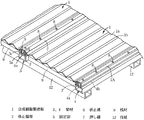
次に本発明の具体的な実施の形態を図面について説明すると、図1、図2において、1は一定幅と長さを有する平面長方形状に形成された合成樹脂製波板であって、幅方向に一定幅毎に山部1aと谷部1bとを連続的に形成していると共に両側端部を下方に向かって垂直に屈折して一定の縦幅を有する係止端部2、2に形成している。この合成樹脂製波板1は、透光性及び強度に優れたアクリル樹脂、塩化ビニル樹脂、ポリカーボネート樹脂等の合成樹脂よりなるものであるが、耐衝撃性に優れているポリカーボネート樹脂製の波板であることが好ましい。   Next, a specific embodiment of the present invention will be described with reference to the drawings. In FIGS. 1 and 2, reference numeral 1 denotes a synthetic resin corrugated plate formed in a planar rectangular shape having a constant width and length. In the direction, a crest 1a and a trough 1b are continuously formed for every constant width, and both end portions are vertically refracted downward to form locking end portions 2 and 2 having a constant vertical width. Forming. This corrugated sheet 1 made of synthetic resin is made of synthetic resin such as acrylic resin, vinyl chloride resin, polycarbonate resin, etc. having excellent translucency and strength, but corrugated sheet made of polycarbonate resin having excellent impact resistance. It is preferable that

また、山部1aと谷部1bとの形状としては、図においては直線状に傾斜した一定幅の上向き傾斜板部と下向き傾斜板部とを幅方向にジグザグ状に連続形成した形状としているが、上向きに円弧状に湾曲した板部と下向きに円弧状に湾曲した板部とを幅方向に連続形成してなる形状や、上向き台形状と下向き台形状との板部を幅方向に連続形成してなる形状等、適宜な形状を採用することができる。なお、この合成樹脂製波板1の両側端部に屈折形成している上記係止端部2、2は、該波板1の山部1a、即ち、上向きに傾斜した板部の上傾端部1a' (図3、図4参照)から下方に向かって垂直に屈折している。   In addition, as the shape of the peak portion 1a and the valley portion 1b, in the figure, the upward inclined plate portion and the downward inclined plate portion that are linearly inclined are continuously formed in a zigzag shape in the width direction. , A shape formed by continuously forming a plate portion curved in an arc shape upward and a plate portion curved in an arc shape downward, or a plate portion of an upward trapezoidal shape and a downward trapezoidal shape continuously in the width direction Appropriate shapes such as the shapes formed can be employed. The engaging end portions 2 and 2 that are refracted at both end portions of the synthetic resin corrugated plate 1 are crests 1a of the corrugated plate 1, that is, an upward inclined end of the plate portion inclined upward. The light is refracted vertically downward from the portion 1a ′ (see FIGS. 3 and 4).

このように形成した合成樹脂製波板1は、その両側係止端部2、2を該合成樹脂製波板1の幅間隔を存して並設した梁材3、4の固定部5にそれぞれ固定されることによって架設状態で取付けられる。この場合、合成樹脂製波板1を2枚以上、幅方向に並設することによって所定幅の屋根を構成するものであり、該屋根の幅方向の中間部には上記一方の梁材3が中間梁材として配設され、屋根の両端部には上記他方の梁材4が端部梁材として配設される。なお、これらの梁材3、4はアルミニウム又はアルミ合金製の中空フレーム材からなり、合成樹脂製波板1の長さに略等しい長さを有している。   The synthetic resin corrugated plate 1 formed in this way is fixed to the fixing portions 5 of the beam members 3 and 4 in which both side locking end portions 2 and 2 are arranged side by side with the width interval of the synthetic resin corrugated plate 1. Each is fixed and installed in an erected state. In this case, a roof having a predetermined width is formed by arranging two or more corrugated synthetic resin corrugated plates 1 in the width direction, and the one beam member 3 is provided in the middle portion of the roof in the width direction. The other beam member 4 is disposed as an end beam member at both ends of the roof. These beam members 3 and 4 are made of a hollow frame material made of aluminum or aluminum alloy, and have a length substantially equal to the length of the synthetic resin corrugated plate 1.

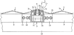
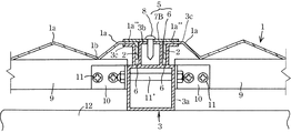
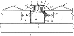
上記中間梁材3は図3に示すように、断面矩形状の中空枠部3aの上面中央部に一定幅と高さを有し且つ両側面が垂直面に形成されている中央突条部3bを全長に亘って一体に突設していると共に、上面両側部にこの中央突条部3bの側面から小間隔を存して高さが該中央突条部3bの高さよりも上記合成樹脂製波板1の厚み分だけ低い両側突条部3c、3cを全長に亘って一体に突設してあり、中央突条部3bの両側面と両側突条部3c、3cの垂直な内側面間の上記小間隔部によって合成樹脂製波板1の係止端部2が挿入、係止可能な上向きに開口した係止溝6、6を形成している。なお、両側突条部3c、3cの上端面は合成樹脂製波板1の上方に向かって傾斜した山部と同じ傾斜度の傾斜面に形成して該合成樹脂製波板1の両側上傾端部1a' の下面を全面的に支持するようにしているが、この上傾端部1a' が水平端部に屈折、形成されている場合には、当然、その上端面は水平面に形成される。   As shown in FIG. 3, the intermediate beam member 3 has a central ridge portion 3b having a constant width and height at the center of the upper surface of the hollow frame portion 3a having a rectangular cross section and having both side surfaces formed as vertical surfaces. Are integrally projected over the entire length, and the height is higher than the height of the central protrusion 3b with a small gap from the side surface of the central protrusion 3b on both sides of the upper surface. Both side ridges 3c, 3c that are lower by the thickness of the corrugated plate 1 are integrally projected over the entire length, and between the side surfaces of the central ridge 3b and the vertical inner side surfaces of the both sides ridges 3c, 3c. The above-mentioned small gap portions form locking grooves 6, 6 that open upward so that the locking end 2 of the synthetic resin corrugated plate 1 can be inserted and locked. In addition, the upper end surfaces of both side ridges 3c, 3c are formed on inclined surfaces having the same inclination as the peaks inclined upward of the synthetic resin corrugated plate 1, and the upper sides of the synthetic resin corrugated plate 1 are inclined upward. The lower surface of the end portion 1a 'is supported entirely, but when the upward inclined end portion 1a' is refracted and formed at the horizontal end portion, the upper end surface is naturally formed on a horizontal plane. The

7はこの中間梁材3の上面に装着する押し縁で、中間梁材3と略同一幅で同一長さのアルミニウム又はアルミ合金製帯板材からなり、中間梁材3の上記両側係止溝6、6にこの中間梁材3の両側に配した合成樹脂製波板1における相対する係止端部2、2をそれぞれ挿入、係止させた状態で、この押し縁7の下面中央部を上記中央突条部3bの上端面に、下面両側部を合成樹脂製波板1、1の相対する上傾端部1a' 、1a' 上にそれぞれ押しつけ、その中央部を長さ方向に一定間隔毎にビス8によって中央突条部3bに固定することにより、この押し縁7の下面両側部と中間梁材3の両側突条部3c、3cの上端面とで合成樹脂製波板1、1の上記上傾端部1a' 、1a' を挟着、固定するように構成している。そして、上記係止溝6とこの押し縁7によって合成樹脂製波板1の係止端部2の固定部5を形成している。   Reference numeral 7 denotes a pressing edge to be mounted on the upper surface of the intermediate beam member 3, which is made of an aluminum or aluminum alloy strip having the same width and length as the intermediate beam member 3, and the both side locking grooves 6 of the intermediate beam member 3. , 6 in the state where the opposite engaging end portions 2 and 2 of the synthetic resin corrugated plate 1 disposed on both sides of the intermediate beam member 3 are inserted and engaged, respectively, Press both sides of the lower surface of the central ridge 3b onto the opposing upwardly inclined ends 1a 'and 1a' of the synthetic resin corrugated plates 1 and 1, respectively, and place the central portion at regular intervals in the length direction. By fixing to the central ridge 3b with screws 8, the bottom surface of the pressing edge 7 and the upper ends of the ridges 3c, 3c of the intermediate beam member 3 are connected to the synthetic resin corrugated plates 1, 1. The upward inclined end portions 1a ′ and 1a ′ are sandwiched and fixed. The locking groove 6 and the pushing edge 7 form a fixing portion 5 of the locking end 2 of the synthetic resin corrugated plate 1.

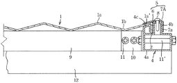
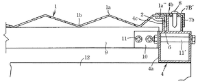
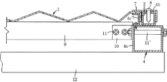
一方、上記端部梁材4は図4に示すように、上記中間梁材3において、両側突条部3c、3cのうち、一方の突条部3cを削除した構造を有している。即ち、断面矩形状の中空枠部4aの上面中央部に上記中間梁材3の中央突条部3bと同大、同形の中央突条部4bを全長に亘って一体に突設していると共に、上面一側部にこの中央突条部4bの側面から小間隔を存して上記中間梁材3の突条部3cと同大、同形の側方突条部4cを全長に亘って一体に突設してなるもので、これらの中央突条部4bと側方突条部4cとの垂直な内側面間の上記小間隔部によって合成樹脂製波板1の係止端部2が挿入、係止可能な上向きに開口した係止溝6を形成している。   On the other hand, as shown in FIG. 4, the end beam member 4 has a structure in which one of the projecting ridge portions 3 c is omitted from the both side ridge portions 3 c and 3 c in the intermediate beam material 3. That is, a central ridge portion 4b having the same size and the same shape as the central ridge portion 3b of the intermediate beam member 3 is integrally projected over the entire length at the center of the upper surface of the hollow frame portion 4a having a rectangular cross section. The side ridge 4c of the same size and shape as the ridge 3c of the intermediate beam member 3 is integrated over the entire length at a small distance from the side of the central ridge 4b on one side of the upper surface. The engaging end 2 of the synthetic resin corrugated plate 1 is inserted by the small gap between the vertical inner surfaces of the central protrusion 4b and the side protrusion 4c. A locking groove 6 that opens upward and can be locked is formed.

また、この端部梁材4における係止溝6と共に押し縁7Aによって合成樹脂製波板1の係止端部2の固定部5を形成してあり、この押し縁7Aは、上記中間梁材3側の押し縁7と同一材料で同一長さを有している一方、その幅は、側方突条部4c上に受止される合成樹脂製波板1の上傾端部1a' と中央突条部4bを全面的に被覆できる幅に形成されてあり、さらに、その外側端部を下方に屈折して中央突条部4bの外側面を被覆する垂直な側片部7aに形成している。そして、上記係止溝6に合成樹脂製波板1の係止端部2を挿入、係止させた状態で、この押し縁7Aの下面を側方突条部4c上に受止されている合成樹脂製1の上記上傾端部1a' 上から中央突条部4bの上端面に押しつけた状態にして、該中央突条部4bの複数箇所に押し縁7Aをビス8によって固定するように構成している。   Further, a fixing portion 5 of the locking end portion 2 of the synthetic resin corrugated sheet 1 is formed by the pressing edge 7A together with the locking groove 6 in the end beam material 4, and the pressing edge 7A is formed of the intermediate beam material. While having the same material and length as the pushing edge 7 on the 3 side, the width thereof is the upper inclined end portion 1a 'of the synthetic resin corrugated plate 1 received on the side ridge portion 4c. The central protrusion 4b is formed to have a width that can cover the entire surface, and further, the outer end is bent downward to form a vertical side piece 7a that covers the outer surface of the central protrusion 4b. ing. Then, with the locking end 2 of the synthetic resin corrugated plate 1 inserted and locked in the locking groove 6, the lower surface of the pushing edge 7A is received on the side protrusion 4c. The pressing edge 7A is fixed to a plurality of locations of the central protruding portion 4b with screws 8 in a state where it is pressed from the upper inclined end portion 1a 'of the synthetic resin 1 to the upper end surface of the central protruding portion 4b. It is composed.

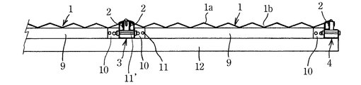
9は合成樹脂製波板1の幅間隔を存して互いに平行に配設した隣接する中間梁材3、3の対向する側面間、又は中間梁材3と端部梁材4の対向する側面間に連結、固定された桟材であって、梁材3、4と同一材料より形成されてあり、この桟材9を梁材3、4の長さ方向に所定間隔毎に梁材3、3又は3、4の対向側面間に連結、固定して、その上面で該上面に対向する合成樹脂製波板1の谷部1bの屈曲下端部を釘着、或いは、ボルト止めすることなく支持している。   9 is between the opposing side surfaces of the adjacent intermediate beam members 3, 3 arranged parallel to each other with a width interval of the synthetic resin corrugated plate 1, or the opposite side surfaces of the intermediate beam member 3 and the end beam member 4. A beam member connected and fixed between the beam members 3 and 4, and is formed of the same material as the beam members 3 and 4. Connected and fixed between 3 or 3 and 4 opposing side surfaces, and supported on the upper surface without nailing or bolting the bent lower end of the valley 1b of the synthetic resin corrugated plate 1 facing the upper surface doing.

桟材9の長さ方向の端部を梁材3又は梁材4の側面に固着するには、平面L字状に屈折してなる金具10を使用して行われ、この金具10の互いに直角に連設している一半部と他半部とを梁材3、4の側面とこの側面部に端面が当接している桟材9の側面とにそれぞれ当てがってビス11又はボルト11' により固着してなるものである。この場合、中間梁材3においては、その両側面に端面を突き合わせた状態で桟材9、9が一直線上に配設され、これらの梁材9、9の対向端部に一半部を固着している金具10、10の他半部同士を該中間梁材3を貫通した共通する一本の共通するボルト11' によって一体に固着されている。   The end of the crosspiece 9 in the length direction is fixed to the side surface of the beam member 3 or the beam member 4 by using a metal fitting 10 refracted in a plane L shape, and the metal fittings 10 are perpendicular to each other. One half and the other half are connected to the side surface of the beam members 3 and 4 and the side surface of the crosspiece member 9 whose end surface is in contact with the side surface portion. It adheres by. In this case, in the intermediate beam member 3, the crosspieces 9 and 9 are arranged in a straight line in a state where the end faces are abutted on both side surfaces, and one half is fixed to the opposite end of the beam members 9 and 9. The other half portions of the metal fittings 10 and 10 are integrally fixed by a common bolt 11 'that passes through the intermediate beam member 3.

上記梁材3、4は、一定間隔毎に並設されている母屋12、12・・・上に直交するように合成樹脂製波板1の幅間隔毎に順次架設され、隣接する梁材3、4上間に上述したように合成樹脂製波板1を張設することによって屋根を構成している。   The beam members 3 and 4 are sequentially installed at every width interval of the synthetic resin corrugated plate 1 so as to be orthogonal to the main buildings 12, 12. As described above, the roof is formed by stretching the corrugated sheet 1 made of synthetic resin.

この屋根の施工方法を簡単に説明すると、屋根の両端側に端部梁材4、4を配置すると共にこれらの端部梁材4、4間に中間梁材3、3・・・を配置して釘やボルト、或いは適宜な金具によって母屋12上に固着する作業と、隣接する中間梁材3と端部梁材4との対向側面間、及び隣接する中間梁材3、3の対向側面間に桟材9を長さ方向に所定間隔毎に連結する作業と、隣接する梁材の固定部5、5間に合成樹脂製波板1を架設状態で張設する作業とによって行われる。この場合、母屋12、 12上に梁材3、4を施工した後、合成樹脂製波板1の張設作業を行ってもよく、梁材3、4や桟材9を施工しながら母屋12、12間に平行に固定した梁材間に合成樹脂製波板1を順次、張設してもよい。なお、隣接する梁材3、3間又は3、4間の対向側面間を連結する上記桟材9は、母屋12上に位置するように配置させることが好ましい。   This roof construction method will be briefly described. End beam members 4, 4 are arranged on both ends of the roof, and intermediate beam members 3, 3, ... are arranged between the end beam members 4, 4. The work of adhering to the purlin 12 with nails, bolts or appropriate metal fittings, between the opposite side surfaces of the adjacent intermediate beam members 3 and the end beam members 4, and between the opposite side surfaces of the adjacent intermediate beam members 3, 3. The crosspiece 9 is connected to the lengthwise direction at predetermined intervals, and the synthetic resin corrugated plate 1 is stretched between the fixing portions 5 and 5 of the adjacent beam members. In this case, after constructing the beam members 3 and 4 on the purlins 12 and 12, the synthetic resin corrugated sheet 1 may be stretched. The synthetic resin corrugated plates 1 may be sequentially stretched between the beam members fixed in parallel between 12. In addition, it is preferable to arrange | position the said crosspiece 9 which connects between the adjacent beam members 3, 3 or between the opposing side surfaces between 3, 4 so that it may be located on the main building 12.

隣接する中間梁材3と端部梁材4の上面間に合成樹脂製波板1を張設するには、該合成樹脂製波板1の谷部1bの下端面を桟材9、9上に受止させた状態にしてその両側係止端部2、2を端部梁材4の固定部5における係止溝6と、中間梁材3の一方(端部梁材4側)の固定部5における係止溝6とにそれぞれ挿入、係止させたのち、端部梁材4の上面に押し縁7Aを当てがって該端部梁材4の側方突条部4c上に支持されている合成樹脂製波板1における一方の上傾端部1a' を押さえた状態でビス8により、該押し縁7Aを端部梁材4の中央突条部4bに固着し、次いで、上記中間梁材3とこの中間梁材3に隣接する中間梁材3との対向する固定部5、5の係止溝6、6内に次の合成樹脂製波板1の両側係止端部2、2を挿入、係止させたのち、両側の係止溝6、6に両側の合成樹脂製波板1の係止端部2、2を挿入、係止させている上記中間梁材3上に押し縁7を当てがって両側の合成樹脂製波板1の対向する上傾端部1a' 、1a' を該押し縁7により押さえた状態にしてビス8によりこの押し縁7を中央突条部3bに固着して、隣接する中間梁材3と端部梁材4間に合成樹脂製波板1を張設する。   In order to stretch the synthetic resin corrugated sheet 1 between the upper surfaces of the adjacent intermediate beam member 3 and the end beam member 4, the lower end surface of the valley portion 1b of the synthetic resin corrugated sheet 1 is placed on the rail members 9, 9. The both side locking end portions 2 and 2 are fixed to the locking groove 6 in the fixing portion 5 of the end beam member 4 and one of the intermediate beam members 3 (the end beam member 4 side). After being inserted and locked in the locking groove 6 in the part 5, the pushing edge 7 A is applied to the upper surface of the end beam member 4 and supported on the side protrusion 4 c of the end beam member 4. The pressing edge 7A is fixed to the central ridge 4b of the end beam member 4 with screws 8 in a state in which one upward inclined end 1a 'of the synthetic resin corrugated sheet 1 is pressed, and then the above-mentioned Both side locking end portions 2 of the next synthetic resin corrugated plate 1 are placed in the locking grooves 6 and 6 of the fixing portions 5 and 5 facing the intermediate beam material 3 and the intermediate beam material 3 adjacent to the intermediate beam material 3. 2 after inserting and locking On both sides of the synthetic resin corrugated plate 1, the engaging edges 2, 2 of the synthetic resin corrugated plates 1 on both sides are inserted and engaged with the grooves 6, 6. With the upwardly inclined end portions 1a 'and 1a' facing each other of the plate 1 being pressed by the pressing edge 7, the pressing edge 7 is fixed to the central ridge 3b with screws 8, and the adjacent intermediate beam 3 and A synthetic resin corrugated sheet 1 is stretched between the end beam members 4.

以下、隣接する中間梁材3、3間に対する合成樹脂製波板1の張設作業も上記同様にして順次行われるものである。このようにして施工された屋根は、屋根材である合成樹脂製波板1の両側係止端部2、2が梁材3、3又は3、4の固定部5、5によって挟着、固定され、且つ、該合成樹脂製波板1の下面が梁材間を連結している桟材9上に支持されているから、強風によっても上下方向にバタつく虞れがなく、従って、この合成樹脂製波板1を釘やボルト等によって桟材9に固定する必要はない。   Hereinafter, the operation of stretching the synthetic resin corrugated sheet 1 between the adjacent intermediate beam members 3 and 3 is sequentially performed in the same manner as described above. The roof constructed in this manner is sandwiched and fixed by the fixing portions 5 and 5 of the beam members 3, 3 or 3, and the both side locking ends 2, 2 of the synthetic resin corrugated sheet 1 that is a roof material. In addition, since the lower surface of the synthetic resin corrugated plate 1 is supported on the crosspiece 9 connecting the beam members, there is no possibility of fluttering in the vertical direction even by strong winds. It is not necessary to fix the resin corrugated plate 1 to the crosspiece 9 with nails or bolts.

図5〜図7は、本発明の別な実施の形態を示すもので、上記実施の形態においては梁材3、4の突条部3c、4c上に支持される、合成樹脂製波板1における両側端部の上傾端部1a' 、1a' を山部1aの傾斜面と同一角度でもって連続的に傾斜させているが、この実施の形態においては、合成樹脂製波板1における両側山部1aの外側部を一定幅、水平状に屈折して上傾端部1a''、1a''を形成し、外側端部をこの上傾端部1a''、1a''(山部1a)の外側端から下方に向かって垂直に屈折させて両側係止端部2、2に形成してなるものである。   5 to 7 show another embodiment of the present invention. In the above embodiment, the synthetic resin corrugated plate 1 is supported on the protrusions 3c and 4c of the beam members 3 and 4. In FIG. The upper inclined end portions 1a ′ and 1a ′ of the both side end portions of FIG. 1 are continuously inclined at the same angle as the inclined surface of the peak portion 1a. The outer part of the peak part 1a is refracted horizontally with a constant width to form the upwardly inclined end parts 1a '', 1a '', and the outer end part is defined as the upwardly inclined end parts 1a '', 1a '' (the peak part) 1a) is formed on both side locking end portions 2 and 2 by refracting vertically downward from the outer end.

従って、この合成樹脂製波板1を張設する中間梁材3及び梁材4としては、断面矩形状の中空枠部3a、4aの上面中央部に両側面が垂直面に形成され、且つ、上端面が水平面に形成されている一定高さの中央突条部3b、4bをそれぞれ突設していると共に、中間梁材3においては中空枠部3aの上面両側部に上記中央突条部3bの側面から小間隔を存して高さが該中央突条部3bの高さよりも上記合成樹脂製波板1の厚み分だけ低い両側突条部3c、3cを全長に亘って一体に突設してあり、この両側突状部3c、3cの上端面を上記水平な上傾端部1a''、1a''を支持する水平上端面に形成していると共に、中央突条部3bの両側面とこれらの両側突条部3c、3cの垂直な内側面間の隙間によって合成樹脂製波板1の係止端部2が挿入、係止可能な上向きに開口した係止溝6、6を形成している。   Therefore, as the intermediate beam member 3 and the beam member 4 for stretching the synthetic resin corrugated plate 1, both side surfaces are formed as vertical surfaces at the center of the upper surface of the hollow frame portions 3a and 4a having a rectangular cross section, and Center ridges 3b and 4b having a fixed height and having a top surface formed in a horizontal plane are respectively provided. In the intermediate beam member 3, the center ridge 3b is provided on both sides of the upper surface of the hollow frame 3a. Both side ridges 3c and 3c are integrally projected over the entire length with a small gap from the side surface of the plate, and the height is lower by the thickness of the synthetic resin corrugated plate 1 than the height of the central ridge 3b. The upper end surfaces of the both side protrusions 3c, 3c are formed as horizontal upper end surfaces that support the horizontal upward inclined end portions 1a '', 1a '' and both sides of the central protrusion 3b. Locking grooves 6, 6 opened upward so that the locking end portion 2 of the synthetic resin corrugated plate 1 can be inserted and locked by a gap between the surface and the vertical inner surface of the both side protrusions 3 c, 3 c. It is formed.

一方、端部梁材4においては、断面矩形状の中空枠部4aの上面中央部に上記中間梁材3の中央突条部3bと同大、同形の上記中央突条部4bを全長に亘って一体に突設していると共に、上面一側部にこの中央突条部4bの側面から小間隔を存して上記中間梁材3の突条部3cと同大、同形の側方突条部4cを全長に亘って一体に突設してなるもので、これらの中央突条部4bと側方突条部4cとの垂直な内側面間の上記小間隔部によって合成樹脂製波板1の係止端部2が挿入、係止可能な上向きに開口した係止溝6を形成している。   On the other hand, in the end beam member 4, the central ridge portion 4 b having the same size and the same shape as the central ridge portion 3 b of the intermediate beam material 3 is provided at the center of the upper surface of the hollow frame portion 4 a having a rectangular cross section over the entire length. And a side ridge of the same size and shape as the ridge 3c of the intermediate beam member 3 with a small gap from the side of the central ridge 4b on one side of the upper surface. The portion 4c is integrally projected over the entire length, and the synthetic resin corrugated plate 1 is formed by the small interval portion between the vertical inner side surfaces of the central protrusion 4b and the side protrusion 4c. A locking groove 6 is formed which is open upward and can be inserted and locked.

そして、係止溝6と共に合成樹脂製波板1の両側係止端部2の固定部5を形成する押し縁としては、中間梁材3の上面を装着する押し縁7Bにおいては、両側突条部3c、3cの外側端間の幅と略同一幅で中間梁材3と同一長さのアルミニウム又はアルミ合金製平帯板材からなり、中間梁材3の上記両側係止溝6、6にこの中間梁材3の両側に配した合成樹脂製波板1における相対する係止端部2、2をそれぞれ挿入、係止させた状態で、この押し縁7Bの下面中央部を上記中央突条部3bの上端面に、下面両側部を合成樹脂製波板1、1の相対する上傾端部1a''、1a''上にそれぞれ押しつけ、その中央部を長さ方向に一定間隔毎にビス8によって中央突条部3bに固定することにより、この押し縁7Bの下面両側部と中間梁材3の両側突条部3c、3cの上端面とで合成樹脂製波板1、1の上記上傾端部1a''、1a''を挟着、固定するように構成している。   And as a pushing edge which forms the fixing | fixed part 5 of the both-side latching edge part 2 of the synthetic resin corrugated sheet 1 with the latching groove 6, in the pushing edge 7B which mounts the upper surface of the intermediate beam material 3, it is a both-side protrusion. It is made of a flat strip made of aluminum or aluminum alloy having substantially the same width as the width between the outer ends of the portions 3c and 3c and the same length as the intermediate beam member 3. In the state in which the opposite engaging end portions 2 and 2 of the synthetic resin corrugated plate 1 disposed on both sides of the intermediate beam member 3 are inserted and engaged, respectively, the center portion of the bottom surface of the pressing edge 7B is set to the central protrusion portion. Press the both sides of the lower surface of the upper surface of 3b onto the opposing upward inclined ends 1a '' and 1a '' of the synthetic resin corrugated plates 1 and 1, respectively, and screw the central part at regular intervals in the length direction. 8 is fixed to the central ridge portion 3b so that both the lower surface side of the pushing edge 7B and the upper end surfaces of the both side ridge portions 3c and 3c of the intermediate beam member 3 are joined. The upper 傾端 portion 1a of the resin corrugated plate 1, 1 '', 1a 'constitute the' clamped, to secure.

一方、係止溝6と共に端部梁材4の固定部を形成する押し縁7B' としては、図7に示すように、その幅は、側方突条部4c上に受止される合成樹脂製波板1の上傾端部1a''の上端面から中央突条部4bの上端面を全面的に被覆できる幅に形成されてあり、さらに、その外側端部を下方に屈折して中央突条部4bの外側面を被覆する垂直な側片部7bに形成している。そして、上記係止溝6に合成樹脂製波板1の係止端部2を挿入、係止させた状態で、この押し縁7B' の下面を側方突条部4cの水平な上端面上に受止されている合成樹脂製波板1の上記上傾端部1a''上から中央突条部4bの水平な上端面に押しつけた状態にして、該中央突条部4bの複数箇所に押し縁7B' をビス8によって固定するように構成している。隣接する梁材の対向側面間を連結してその上面で合成樹脂製波板1の谷部下端を支持する桟材9の連結構造や、母屋12に対する梁材3、4の取付構造等は上記実施の形態と同様であるので、同一部分に同一符号を付して詳細な説明を省略する。   On the other hand, as shown in FIG. 7, the width of the pushing edge 7B ′ that forms the fixing portion of the end beam member 4 together with the locking groove 6 is a synthetic resin received on the side protrusion 4c. It is formed to have a width that can cover the entire upper end surface of the central protrusion 4b from the upper end surface of the upward inclined end portion 1a '' of the corrugated plate 1. Further, the outer end portion is refracted downward to be centered. It is formed on a vertical side piece 7b that covers the outer surface of the ridge 4b. Then, with the locking end 2 of the synthetic resin corrugated plate 1 inserted and locked in the locking groove 6, the lower surface of the pushing edge 7B 'is placed on the horizontal upper end surface of the side ridge 4c. In a state where the corrugated plate 1 made of synthetic resin is pressed onto the horizontal upper end surface of the central ridge 4b from above the above-inclined end 1a '', the central ridge 4b is placed at a plurality of locations. The pushing edge 7B 'is configured to be fixed by a screw 8. The connecting structure of the crosspiece 9 that connects the opposite side surfaces of the adjacent beam members and supports the lower end of the trough of the synthetic resin corrugated sheet 1 on the upper surface, the mounting structure of the beam members 3 and 4 to the purlin 12 etc. Since it is the same as that of embodiment, the same code | symbol is attached | subjected to the same part and detailed description is abbreviate | omitted.

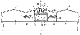
図8、図9は、本発明のさらに別な実施の形態を示すもので、上記いずれの実施の形態においても、合成樹脂製波板1の係止端部2の固定手段としての押し縁7(7A、7B、7B' )等を梁材3、4の中央突条部3b、4bに固着するにはビス8によって行っているが、この実施の形態においてはビスを使用することなく押し縁7C、7C' を固着している。   8 and 9 show still another embodiment of the present invention. In any of the above embodiments, the pushing edge 7 as a fixing means of the locking end 2 of the synthetic resin corrugated plate 1 is shown. (7A, 7B, 7B ') etc. are fixed to the central ridges 3b, 4b of the beam members 3, 4 by screws 8, but in this embodiment, the pushing edges are used without using screws. 7C and 7C 'are fixed.

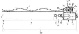
即ち、梁材3、4における中央突条部3b、4bに代えて、中空枠部3a、4aの上面中央部に幅方向に一定間隔を存して上端部の相対する内側面にフック形状の係止爪31、31;41、41をそれぞれ形成している一定高さの一対の係止突条部3a' 、3a' ;4a' 、4a' を突設している一方、中間梁材3側の押し縁7Cにおいてはその下面中央部に、上記係止突条部3a' 、3a' 間に挿入可能で下端部対向内側面に上記係止爪31、31に係止する係止爪14、14をそれぞれ形成している一対の係止片13、13を下方に向かって突設してあり、端部梁材4側の押し縁7C' においてはその下面に、上記係止突条部4a' 、4a' 間に挿入可能で下端部対向内側面に上記係止爪41、41に係止する係止爪14、14をそれぞれ形成している一対の係止片13、13を下方に向かって突設していると共に該押し縁7Cの一側部を下方に向かって垂直に屈折させて外側係止突条部4a' の外側面に係止状態で当接させる垂直な側片部7cに形成している。   That is, instead of the central ridges 3b and 4b in the beam members 3 and 4, hook-shaped hooks are formed on the inner side surfaces of the upper ends facing each other with a certain interval in the width direction at the center of the upper surface of the hollow frame portions 3a and 4a. A pair of locking protrusions 3a ', 3a'; 4a ', 4a' of a fixed height forming the locking claws 31, 31; 41, 41, respectively, project from the intermediate beam 3 In the pressing edge 7C on the side, a locking claw 14 that can be inserted between the locking protrusions 3a 'and 3a' at the center of the lower surface and that locks the locking claws 31 and 31 on the inner surface facing the lower end. , 14 projecting downwardly from the pair of locking pieces 13, 14, and the locking ridges on the bottom surface of the pushing edge 7 C ′ on the end beam member 4 side 4a ′, a pair of locking pieces 13, 13 that can be inserted between 4a ′ and that respectively form locking claws 14, 14 that lock the locking claws 41, 41 on the inner surface facing the lower end. One side of the pushing edge 7C The are formed in the vertical side piece portion 7c for abutment with the locking state on the outer surface of the refracted vertically outer locking protrusions 4a 'downward.

そして、梁材3、4における中空枠部3aの上面側部に突設している突条部3c、4cと上記係止突状部3a' 、4a' との対向する側面間の隙間によって合成樹脂製波板1の係止端部2を挿入、係止させる係止溝6を形成している。その他の構成については、上記実施の形態と同様であるので、同一部分には同一符号を付して詳細な説明を省略する。   The beam members 3 and 4 are combined by a gap between the opposing side surfaces of the protrusions 3c and 4c protruding from the upper surface side of the hollow frame portion 3a and the locking protrusions 3a 'and 4a'. A locking groove 6 for inserting and locking the locking end 2 of the resin corrugated plate 1 is formed. Since other configurations are the same as those in the above-described embodiment, the same portions are denoted by the same reference numerals, and detailed description thereof is omitted.

このように構成したので、隣接する梁材3、3又は3、4の係止溝6に合成樹脂製波板1の係止端部2を挿入、係止させたのち、上記押し縁7C、7C' の下面に突設している一対の係止片13、13を梁材3、4の上記一対の係止突状部3a' 、3a' 間又は4a' 、4a' 間に挿入して互いに係止爪13、31;13、41同士を抜け止め状態で係止させることにより、これらの押し縁7C、7C' の下面と側部の突条部3c、4cの上面間で合成樹脂製波板1の係止端部2を挟着、固定させるものである。   Since it comprised in this way, after inserting and latching the latching end part 2 of the synthetic resin corrugated sheet 1 in the latching groove | channel 6 of the adjacent beam material 3, 3 or 3, 4, the said pushing edge 7C, A pair of locking pieces 13 and 13 projecting from the lower surface of 7C 'are inserted between the pair of locking projections 3a' and 3a 'of the beam members 3 and 4 or between 4a' and 4a '. By locking the locking claws 13, 31; 13, 41 with each other in a retaining state, a synthetic resin is formed between the lower surface of these pushing edges 7C, 7C 'and the upper surface of the side protrusions 3c, 4c. The locking end 2 of the corrugated plate 1 is clamped and fixed.

なお、以上のいずれの実施の形態においても、梁材3、4として中空枠部3a、4aの上面に中央突条部3b、4bと側方の突条部3c、4cとを一体に形成しているが、図10、図11に示すように、少なくとも側方の突条部3c''、4c''を別体に形成しておき、合成樹脂製波板1の施工時に、中央突条部3b(4b)と該突条部3c''(4c'')とで合成樹脂製波板1の係止端部2を挟着するようにこの突条部3c''(4c'')を中空枠部3a、4aの上面側部上にビス止めすることにより固着してもよい。この場合、突条部3c''(4c'')としては、断面コ字状に形成しておき、その下端水平フランジ部を中空枠部3a、4aの上面側部上に重ね合わせてビス止めするように構成しておくことが望ましい。   In any of the above embodiments, the central ribs 3b, 4b and the side ribs 3c, 4c are integrally formed on the upper surface of the hollow frame portions 3a, 4a as the beam members 3, 4. However, as shown in FIGS. 10 and 11, at least the side ridges 3c '' and 4c '' are formed separately, and the central ridge is formed when the synthetic resin corrugated sheet 1 is constructed. The protruding portion 3c '' (4c '') so as to sandwich the locking end 2 of the synthetic resin corrugated plate 1 between the portion 3b (4b) and the protruding portion 3c '' (4c ''). May be fixed by screwing on the upper side portions of the hollow frame portions 3a, 4a. In this case, the protruding portion 3c '' (4c '') is formed in a U-shaped cross section, and its lower end horizontal flange portion is overlapped on the upper surface side portion of the hollow frame portions 3a, 4a and screwed. It is desirable to make it so.

本発明の一つの実施の形態を示す一部の簡略斜視図。1 is a partial simplified perspective view showing an embodiment of the present invention. その簡略縦断正面図。The simplified longitudinal front view. 合成樹脂製波板の係止端部が中間梁材に固定された状態の縦断正面図。The longitudinal cross-sectional front view of the state by which the latching edge part of the synthetic resin corrugated sheet was fixed to the intermediate beam material. 合成樹脂製波板の係止端部が端部梁材に固定された状態の縦断正面図。The longitudinal cross-sectional front view of the state by which the latching edge part of the synthetic resin corrugated sheet was fixed to the edge part beam material. 本発明の別な実施の形態を示す一部の簡略斜視図。The one part simplified perspective view which shows another embodiment of this invention. その合成樹脂製波板の係止端部が中間梁材に固定された状態の縦断正面図。The longitudinal cross-sectional front view of the state by which the latching edge part of the synthetic resin corrugated sheet was fixed to the intermediate beam material. 合成樹脂製波板の係止端部が端部梁材に固定された状態の縦断正面図。The longitudinal cross-sectional front view of the state by which the latching edge part of the synthetic resin corrugated sheet was fixed to the edge part beam material. 本発明のさらに別な実施の形態を示す中間梁材部分の縦断正面図。The longitudinal cross-sectional front view of the intermediate beam material part which shows another embodiment of this invention. その端部梁材部分の縦断正面図。The longitudinal section front view of the end beam material part. 側方の突条部を別体に形成した場合の中間梁材部分の縦断正面図。The longitudinal cross-sectional front view of the intermediate beam material part at the time of forming a side protrusion part in another body. その端部梁材部分の縦断正面図。The longitudinal section front view of the end beam material part.

符号の説明Explanation of symbols

1 合成樹脂製波板
2 係止端部
3、4 梁材
5 固定部
6 係止溝
7 押し縁
9 桟材
12 母屋
DESCRIPTION OF SYMBOLS 1 Synthetic resin corrugated sheet 2 Locking edge part 3, 4 Beam material 5 Fixing part 6 Locking groove 7 Push edge 9 Crosspiece
12 Purlin

Claims (6)

幅方向に山部と谷部とを連続的に形成している合成樹脂製波板の両側端部を梁材に固定してなる波板の取付構造であって、合成樹脂製波板の両側端部に下方に向かって係止端部を屈折、形成している一方、上記梁材にその係止端部の固定部を設けてあり、この固定部に上記合成樹脂製波板の係止端部を係止させた状態で固定していることを特徴とする波板の取付構造。   A corrugated sheet mounting structure in which both side ends of a synthetic resin corrugated sheet in which peaks and valleys are continuously formed in the width direction are fixed to a beam material, and both sides of the synthetic resin corrugated sheet While the locking end is refracted and formed downward at the end, a fixing portion of the locking end is provided on the beam material, and the synthetic resin corrugated plate is locked to the fixing portion. A corrugated plate mounting structure characterized in that the end portion is fixed in a locked state. 梁材に設けている固定部は上向きに開口した係止溝と梁材の上面に装着する押し縁とからなり、上記係止溝に合成樹脂製波板の係止端部を挿入、係止させた状態で梁材の上面に支持されている波板の側端部を押し縁の下面と梁材の上端面とで挟着、固定するように構成していることを特徴とする請求項1に記載の波板の取付構造。   The fixed part provided in the beam material consists of a locking groove that opens upward and a pushing edge that is attached to the upper surface of the beam material. The locking end of the synthetic resin corrugated plate is inserted into the locking groove and locked. The side end portion of the corrugated sheet supported on the upper surface of the beam member in a state of being held is sandwiched and fixed between the lower surface of the pressing edge and the upper end surface of the beam member. 1. A corrugated mounting structure according to 1. 両側の梁材の対向側面間に該梁材の長さ方向に所定間隔毎に桟材を固着してあり、この桟材に合成樹脂製波板を釘着等により固着することなく該合成樹脂製波板の谷部の下面を支持させていることを特徴とする請求項1又は請求項2に記載の波板の取付構造。   Crosspieces are fixed at predetermined intervals in the longitudinal direction of the beam members between the opposite side surfaces of the beam members on both sides, and the synthetic resin is not fixed to the crosspieces by attaching a synthetic resin corrugated plate by nailing or the like. The corrugated sheet mounting structure according to claim 1 or 2, wherein a bottom surface of a trough portion of the corrugated sheet is supported. 梁材の両側部に係止溝を形成してあり、これらの係止溝に該梁材の両側方に配設した合成樹脂製波板の対向する係止端部を係止させていることを特徴とする請求項1又は請求項2に記載の波板の取付構造。   Locking grooves are formed on both sides of the beam material, and the opposite locking ends of the synthetic resin corrugated plates disposed on both sides of the beam material are locked in these locking grooves. The corrugated sheet mounting structure according to claim 1, wherein the corrugated sheet mounting structure is provided. 所定間隔毎に並設している母屋上に梁材を該母屋の長さ方向に所定間隔毎に架設状態で固着してあり、隣接する梁材の上面間に合成樹脂製波板を張設していることを特徴とする請求項1ないし請求項4のうち、いずれか1項に記載の波板の取付構造。   A beam material is fixed to the main building that is arranged in parallel at predetermined intervals in the length direction of the main building in a state of being installed at predetermined intervals, and a synthetic resin corrugated plate is stretched between the upper surfaces of adjacent beam materials. The corrugated sheet mounting structure according to any one of claims 1 to 4, wherein the corrugated sheet mounting structure is provided. 請求項1〜5のいずれか1項に記載の波板の取付構造に使用される合成樹脂製波板であって、山部と谷部とが連続的に形成されていると共に、両側端の山部から下方に向かって屈折してなる係止端部を形成していることを特徴とする合成樹脂製波板。   It is a synthetic resin corrugated sheet used for the corrugated sheet mounting structure according to any one of claims 1 to 5, wherein a crest and a trough are formed continuously, and A synthetic resin corrugated board having a locking end formed by bending downward from a peak.
JP2004119896A 2004-04-15 2004-04-15 Corrugated plate mounting structure and synthetic resin corrugated plate used for same Pending JP2005299301A (en)

Priority Applications (1)

Application Number Priority Date Filing Date Title
JP2004119896A JP2005299301A (en) 2004-04-15 2004-04-15 Corrugated plate mounting structure and synthetic resin corrugated plate used for same

Applications Claiming Priority (1)

Application Number Priority Date Filing Date Title
JP2004119896A JP2005299301A (en) 2004-04-15 2004-04-15 Corrugated plate mounting structure and synthetic resin corrugated plate used for same

Publications (1)

Publication Number Publication Date
JP2005299301A true JP2005299301A (en) 2005-10-27

Family

ID=35331185

Family Applications (1)

Application Number Title Priority Date Filing Date
JP2004119896A Pending JP2005299301A (en) 2004-04-15 2004-04-15 Corrugated plate mounting structure and synthetic resin corrugated plate used for same

Country Status (1)

Country Link
JP (1) JP2005299301A (en)

Cited By (1)

* Cited by examiner, † Cited by third party
Publication number Priority date Publication date Assignee Title
KR200446045Y1 (en) 2009-06-04 2009-09-21 김학수 Sewer odor reverse protection trench cover

Cited By (1)

* Cited by examiner, † Cited by third party
Publication number Priority date Publication date Assignee Title
KR200446045Y1 (en) 2009-06-04 2009-09-21 김학수 Sewer odor reverse protection trench cover

Similar Documents

Publication Publication Date Title
JP4954746B2 (en) Skylight support structure
US7546708B2 (en) Light transmission panels, retaining clip and a combination thereof
US8056289B1 (en) Dual glazing panel system
US5390453A (en) Structural members and structures assembled therefrom
US6164024A (en) Architectural glazing panel system and retaining clip therefor
CN101227988B (en) A cladding sheet and cladding component
US5867949A (en) Building structure
AU2011232748B2 (en) Truss System
US9528266B2 (en) Dual glazing panel system
US9151056B2 (en) Dual glazing panel system
AU8272387A (en) Panel mounting system
JP3894931B2 (en) Solar panel mounting base
EP1493877B1 (en) Waterproof structure of building
JP2005299301A (en) Corrugated plate mounting structure and synthetic resin corrugated plate used for same
JP5821084B2 (en) Folded plate roof material, connection structure of the folded plate roof material, and a coupling tool used for connecting the folded plate roof material.
US7591115B2 (en) Roof tile support arrangement
JP2561411Y2 (en) Assembled buildings such as carports
JP2927709B2 (en) Roof structure such as greenhouse
CA2885428C (en) Dual glazing panel system
JP7721133B2 (en) Ceiling support bracket, its installation method, ceiling material mounting structure using this ceiling support bracket, and exterior structure
JP4264419B2 (en) Roof panel
JP2006144318A (en) Daylighting roof
JP2898244B2 (en) Support structure for folded roof
JP3389167B2 (en) Roof repair structure and repair method
JPH10259650A (en) Roof structure of building and its construction method

Legal Events

Date Code Title Description
A621 Written request for application examination

Effective date: 20070406

Free format text: JAPANESE INTERMEDIATE CODE: A621

A977 Report on retrieval

Free format text: JAPANESE INTERMEDIATE CODE: A971007

Effective date: 20090715

A131 Notification of reasons for refusal

Effective date: 20090728

Free format text: JAPANESE INTERMEDIATE CODE: A131

A02 Decision of refusal

Effective date: 20091124

Free format text: JAPANESE INTERMEDIATE CODE: A02