JP2005299224A - Seawater exchange breakwater - Google Patents
Seawater exchange breakwater Download PDFInfo
- Publication number
- JP2005299224A JP2005299224A JP2004116814A JP2004116814A JP2005299224A JP 2005299224 A JP2005299224 A JP 2005299224A JP 2004116814 A JP2004116814 A JP 2004116814A JP 2004116814 A JP2004116814 A JP 2004116814A JP 2005299224 A JP2005299224 A JP 2005299224A
- Authority
- JP
- Japan
- Prior art keywords
- caisson
- sea
- water
- caisson body
- water conduit
- Prior art date
- Legal status (The legal status is an assumption and is not a legal conclusion. Google has not performed a legal analysis and makes no representation as to the accuracy of the status listed.)
- Pending
Links
- 239000013535 sea water Substances 0.000 title claims abstract description 42
- XLYOFNOQVPJJNP-UHFFFAOYSA-N water Substances O XLYOFNOQVPJJNP-UHFFFAOYSA-N 0.000 claims abstract description 87
- 238000005192 partition Methods 0.000 claims abstract 2
- 239000000945 filler Substances 0.000 claims description 12
- 238000004519 manufacturing process Methods 0.000 abstract description 9
- 239000000463 material Substances 0.000 abstract description 9
- 239000004576 sand Substances 0.000 description 15
- 238000009434 installation Methods 0.000 description 8
- 230000009194 climbing Effects 0.000 description 7
- 229910000831 Steel Inorganic materials 0.000 description 5
- 239000010959 steel Substances 0.000 description 5
- 238000010276 construction Methods 0.000 description 4
- 238000005520 cutting process Methods 0.000 description 3
- 230000000694 effects Effects 0.000 description 3
- 238000002834 transmittance Methods 0.000 description 3
- 238000003780 insertion Methods 0.000 description 2
- 230000037431 insertion Effects 0.000 description 2
- 238000012856 packing Methods 0.000 description 2
- 238000003466 welding Methods 0.000 description 2
- 241000555825 Clupeidae Species 0.000 description 1
- 230000002411 adverse Effects 0.000 description 1
- 238000009360 aquaculture Methods 0.000 description 1
- 244000144974 aquaculture Species 0.000 description 1
- 230000002238 attenuated effect Effects 0.000 description 1
- 230000000903 blocking effect Effects 0.000 description 1
- 230000006866 deterioration Effects 0.000 description 1
- 239000011796 hollow space material Substances 0.000 description 1
- 238000000034 method Methods 0.000 description 1
- 238000012986 modification Methods 0.000 description 1
- 230000004048 modification Effects 0.000 description 1
- 235000019512 sardine Nutrition 0.000 description 1
- 238000000638 solvent extraction Methods 0.000 description 1
- 238000011144 upstream manufacturing Methods 0.000 description 1
- 239000003643 water by type Substances 0.000 description 1
Images
Classifications
-
- Y—GENERAL TAGGING OF NEW TECHNOLOGICAL DEVELOPMENTS; GENERAL TAGGING OF CROSS-SECTIONAL TECHNOLOGIES SPANNING OVER SEVERAL SECTIONS OF THE IPC; TECHNICAL SUBJECTS COVERED BY FORMER USPC CROSS-REFERENCE ART COLLECTIONS [XRACs] AND DIGESTS
- Y02—TECHNOLOGIES OR APPLICATIONS FOR MITIGATION OR ADAPTATION AGAINST CLIMATE CHANGE
- Y02A—TECHNOLOGIES FOR ADAPTATION TO CLIMATE CHANGE
- Y02A10/00—TECHNOLOGIES FOR ADAPTATION TO CLIMATE CHANGE at coastal zones; at river basins
- Y02A10/11—Hard structures, e.g. dams, dykes or breakwaters
Landscapes
- Revetment (AREA)
Abstract
Description
本発明は、海水交換防波堤に係わり、特に深度が浅い港湾に設置するのに適した海水交換防波堤に関する。 The present invention relates to a seawater exchange breakwater, and more particularly to a seawater exchange breakwater suitable for installation in a shallow port.
従来より、港湾においては、内海の設備や船舶を波から保護するために、港湾への出入用の航路以外の部分は防波堤により囲んだ構成となっている。防波堤は元来、海底から海面上に延出するように設けられて外海から内海に打ち寄せる波を遮断するものであり、これによって、防波堤の内海側の閉鎖海域を外海側の外海に比較して穏やかなものとすることができる。 Conventionally, in harbors, in order to protect inland sea facilities and ships from waves, portions other than the seaway for entering and exiting the harbor are surrounded by a breakwater. The breakwater is originally provided so as to extend from the bottom of the sea to the surface of the sea, blocking the waves rushing from the open sea to the inland sea. By this, the closed sea area of the breakwater is compared with the open sea on the open sea side. Can be calm.
防波堤の機能としては、外海の波浪が内海に及ぶのを低減する波透過率の低減と、防波堤で波浪が反射してこの反射した波浪が外海の漁場等に対して悪影響を及ぼすことを防止することが要求される。 The function of the breakwater is to reduce the wave transmittance to reduce the ocean waves from reaching the inland sea, and to prevent the waves reflected by the breakwater from adversely affecting the fishing ground in the ocean. Is required.
また、外海に対して閉鎖性をもつ内海は、外海の波浪等の自然条件に対しても穏やかであるために、船舶の係留、臨界工場等の建設、養殖いけすの設置等、種々の目的に利用されるが、一方、防波堤により区画された内海は、閉鎖性をもつために外海の海水との交換(交流)が行われ難く、そのために内海の海水が汚染する問題が深刻化しており、内海の閉鎖水域の水質の保全を図ることが要求される。 In addition, the inland sea, which is closed to the open sea, is calm against natural conditions such as waves in the open sea, so it can be used for various purposes such as mooring ships, construction of critical factories, and installation of aquaculture sardines. On the other hand, the inland sea divided by the breakwater is closed, so it is difficult to exchange (exchange) with the seawater in the open sea, and the problem of contaminating the seawater in the inland sea is becoming serious. It is required to maintain the water quality of the closed waters in the inland sea.
このため、従来より、外海の海水を内海に取り入れて海水の交換が図れるようにした防波堤が種々提案されている。 For this reason, conventionally, various breakwaters have been proposed in which seawater from outside seas is taken into the inland seas to exchange seawater.
例えば、特許文献1では、波浪に対向して配置される防波堤の前面壁にスリットを形成し、前面壁よりも後方にスリットに連通する遊水部を形成し、該遊水部に連通するとともに内部に絞り部を形成した消波管を背面壁に貫通させて港湾側に連通させ、消波管の周囲に中空の空間部を形成している。
For example, in
また、特許文献2では、防波堤を構成するケーソンに、外域側から内域側に貫通する開口部を設け、開口部内には、上下に複数の波遡上板を配置し、該波遡上板は、その波遡上部が斜面となっている。従って、水位が所定の範囲内の場合に、外海側からの波により海水が波遡上部を遡上して、内海側に流入することになる。また、波遡上板の内海側においては、海面が穏やかな状態なので、波遡上板の最も高い境界部を海水が越えられない。従って、海水は開口部内において外海側から内海側に一方的に流入する。また、外海側から内海側に流入した海水は濾層により濾過されるようにしている。
Moreover, in
また、特許文献3では、ケーソン下部本体の上面に、ケーソン内海側面に平均潮位と略一致する高さの乗り越え頂部を有し、乗り越え頂部からケーソン外海側面に向かって所要の下り勾配で傾斜した海水導入斜面を備え、ケーソン下部本体におけるケーソン外海側面の上部近傍位置に、下端が平均潮位に略一致し鉛直上方に延設された消波壁を備えている。
前記特許文献1〜3に示される海水交換防波堤によれば、スリットや貫通孔や傾斜面の消波部を備えることによって、消波効果が発揮されると共に、外海の海水を閉鎖海域である内海に流入させることができ、よって海水の交換が可能となり閉鎖海域内の水質の悪化を抑止することができる。
According to the seawater exchange breakwaters shown in
一方、近年では、上記した如き防波堤の建設のための工期を短縮するために、鋼とコンクリートからなり且つ砂や土砂等の充填物を充填する充填空間を備えたハイブリッド構造のケーソン本体を工場等で製造し、製造したケーソン本体は前記充填空間による浮力を利用して水に浮かべた状態で現地まで曳航し、現地において前記充填空間に砂等の充填物を充填することによりケーソン本体を海底に沈め、このようにして複数のケーソン本体を幅方向に並べて設置することにより防波堤を構築することが行われている。このとき、ケーソン本体は構造部材と充填した砂等の重量によって設置位置に固定される。 On the other hand, in recent years, in order to shorten the construction period for the construction of the breakwater as described above, a caisson body having a hybrid structure comprising a filling space made of steel and concrete and filled with a filler such as sand or earth and sand is used in a factory or the like. The caisson body manufactured by the above-mentioned method is towed to the site while floating in water using the buoyancy of the filling space, and the caisson body is filled on the seabed by filling the filling space with a filler such as sand. It has been practiced to construct a breakwater by sinking and thus installing a plurality of caisson bodies side by side in the width direction. At this time, the caisson body is fixed to the installation position by the weight of the structural member and the filled sand or the like.
しかし、前記特許文献1、2では消波するために複雑な形状を有しており、このために、多量の鋼構造物を必要として重量が大きくなる問題がある。即ち、特許文献1、2のケーソン本体を水に浮かべて曳航しようとした場合には、浮力を得るために転倒モーメント等から決まるケーソン本体の厚さ寸法を余分に大きくする必要がある。即ち、防波堤は海底から海面上に延出される高さを有して設置する必要があり、このためにケーソン本体は、曳航時には下端が海底に当たらないように、大きく海面上に浮上させて曳航する必要がある。このため、重量が大きい特許文献1、2のケーソン本体では、揚力を得るためにケーソン本体の厚さ寸法を余分に大きくする必要がある。従って、特許文献1、2のケーソン本体では、重量、厚さ寸法が必要以上に大きくなり、このために製造コストが増加して不経済になるという問題がある。
However, Patent Documents 1 and 2 have a complicated shape in order to eliminate the wave, and thus there is a problem that a large amount of steel structure is required and the weight is increased. In other words, when trying to tow the caisson body of
また、上記したように曳航のための浮力を得るために大型化したケーソン本体は、深度が浅い港湾等に対して設置できない場合がある。即ち、特許文献1、2のケーソン本体は、大型で大深度の防波堤の構築には適用できるが、深度が浅い小型の防波堤への適用には不向きであり、よって適用する海域が限定されるという問題がある。
In addition, as described above, the caisson body that has been enlarged in order to obtain buoyancy for towing may not be installed in a shallow port or the like. That is, the caisson body of
また、特許文献1、2ではケーソン本体が厚さ方向に非対称な形状を有しているために、厚さ方向の重量がアンバランスになって傾くという問題がある。このようにケーソン本体が傾くと、曳航時に転倒する危険があると共に、ケーソン本体の充填空間に充填物を充填して沈下させる際にケーソン本体が傾いたまま設置されてしまうという問題がある。
In
このような問題に対しては、ケーソン本体の曳航時にケーソン本体が傾かないように、ケーソン本体にカウンタウェイトを取り付けて厚さ方向の重量をバランスさせることが行われているが、このようにカウンタウェイトを取り付けると、そのカウンタウェイトの重量分の浮力を更に増加する必要があるために、ケーソンの厚さ寸法が更に余分に増加し、よって製造コストも更に増加するという問題がある。 To counter such problems, counterweights are attached to the caisson body to balance the weight in the thickness direction so that the caisson body does not tilt when the caisson body is towed. When the weight is attached, it is necessary to further increase the buoyancy corresponding to the weight of the counterweight, so that there is a problem that the thickness of the caisson is further increased and the manufacturing cost is further increased.
一方、特許文献3のケーソン本体は、比較的簡単な構造であるために製造が容易であると共に、重量も小さく、更に、厚さ方向の重量もバランスし易い構造であるため、深度が浅い小型の防波堤にも適用することができる。 On the other hand, the caisson body of Patent Document 3 has a relatively simple structure and is easy to manufacture, has a small weight, and is easy to balance the weight in the thickness direction. It can also be applied to other breakwaters.
しかし、前記特許文献1〜3の何れにおいても、ケーソン本体の充填空間に充填物を充填してケーソン本体を沈下させて設置する際に問題を有していた。
However, any of
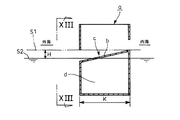
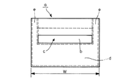
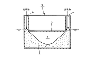
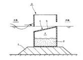
即ち、前記特許文献3の場合を例にとって説明すると、図12、図13に示す如く、ケーソン本体aの上下中間位置には外海から内海に向かって上り勾配を有して厚みK方向に形成した海水導入斜面bによる消波部cが設けてあり、前記海水導入斜面bの下部には、浮力を確保するための所要の容積を有し且つ後で充填物を充填して沈下を行わせるための充填空間dを設けている。そして、図13に示す如くケーソン本体aの幅W方向の両端部には上端が開放された投入口eが設けてあり、この投入口eは前記充填空間dに連通している。 That is, the case of Patent Document 3 will be described as an example. As shown in FIGS. 12 and 13, the caisson main body a is formed in the thickness K direction with an upward slope from the open sea to the inland sea at the upper and lower intermediate positions of the caisson body a. A wave-dissipating part c is provided by a seawater introduction slope b, and the lower part of the seawater introduction slope b has a required volume for securing buoyancy and is filled later with a filler to cause subsidence. The filling space d is provided. And as shown in FIG. 13, the insertion opening e with which the upper end was open | released is provided in the both ends of the width W direction of the caisson main body a, and this insertion opening e is connected to the said filling space d.
従って、上記ケーソン本体aは、前記充填空間dによる浮力を利用して水に浮かせる。このとき、ケーソン本体aは設置時の水位S1が曳航時の水位S2より所要の高さHだけ高くなるように浮上させ、この状態で現地まで曳航し、現地では図14に示すように前記投入口eから砂等を投入して前記充填空間dに充填し、砂等の重量によってケーソン本体aを図15に示す如く海底の基礎マウンドf上に沈下させて設置するようにしている。 Therefore, the caisson body a is floated on water by using the buoyancy generated by the filling space d. At this time, the caisson body a is lifted so that the water level S1 at the time of installation is higher than the water level S2 at the time of towing by a required height H, and towed to the site in this state. Sand or the like is introduced from the mouth e to fill the filling space d, and the caisson body a is submerged on the foundation mound f of the seabed by the weight of sand or the like as shown in FIG.
しかし、前記したようにケーソン本体aの充填空間dの上部には海水導入斜面bを形成する板が存在しているために、前記ケーソン本体aの幅方後端部の投入口eから砂等を投入しても、砂等は所要の安息角で流入されるのみであるために、図14、図15に示す如く充填空間dに砂等が充填されない略V字状の未充填部gが生じ、このために砂等の充填量が不足し、よって計画したケーソン本体aの固定重量が得られないという問題を生じる。 However, as described above, since the plate forming the seawater introduction slope b exists at the upper part of the filling space d of the caisson main body a, sand or the like is introduced from the inlet e at the rear end portion in the width direction of the caisson main body a. Since the sand and the like are only flown at the required angle of repose even if it is inserted, there is a substantially V-shaped unfilled portion g in which the sand or the like is not filled in the filling space d as shown in FIGS. As a result, there is a problem that the filling amount of sand or the like is insufficient, and thus the planned fixed weight of the caisson body a cannot be obtained.
本発明は、上記実情に鑑みてなしたものであり、ケーソン本体の構成が簡単且つ軽量で厚みを小さくできることにより安価に製造でき、更に充填空間に対して充填物を確実に充填できるようにした海水交換防波堤を提供することを目的とするものである。 The present invention has been made in view of the above circumstances, and the caisson main body has a simple and lightweight structure that can be manufactured at low cost by reducing the thickness, and further, the filling space can be reliably filled with a filling material. The purpose is to provide a seawater exchange breakwater.
請求項1に係る発明は、ケーソン本体を水に浮かべて曳航した後内部に充填物を充填することにより港湾の海底に設置して外海と内海とを区画する海水交換防波堤であって、前記ケーソン本体に、該ケーソン本体を波の進行方向で水平に貫通する導水路と、該導水路の内底部に設けられ外海側から内海側に向かって上り傾斜の乗り越え傾斜面を有する傾斜部材と、を備えたことを特徴とする海水交換防波堤である。
The invention according to
請求項2に係る発明は、前記導水路の下面が、該導水路の下側への充填物の回り込みを助けるように下方に突出した突出下面を有することを特徴とする請求項1に記載の海水交換防波堤である。
The invention according to
請求項3に係る発明は、前記傾斜部材が、導水路の内海側の内底部に設けられたことを特徴とする請求項1又は2に記載の海水交換防波堤である。
The invention according to claim 3 is the seawater-exchange breakwater according to
請求項4に係る発明は、前記傾斜部材を、ケーソン本体の海底設置時に導水路に固定するようにしたことを特徴とする請求項1〜3のいずれか1つに記載の海水交換防波堤である。
The invention according to
本発明の海水交換防波堤によれば、ケーソン本体の厚さ方向に導水路が貫通配置された簡略な構造であるため、製造が容易であり、しかもケーソン本体に用いられる鋼材の重量を従来に比して大幅に低減することができ、更に、ケーソン本体は、導水路が設けられている部分以外の全てを充填物を充填するための充填空間とすることができる。従って、ケーソン本体を水に浮かべて曳航する際の浮力を大きくとることができて曳航のための喫水が上がり、従って、従来の如くケーソン本体の厚さ寸法を余分に増加させる必要をなくして、ケーソン本体の製造コストを大幅に低減できる効果がある。 According to the seawater exchange breakwater of the present invention, since it has a simple structure in which a water conduit is penetrated in the thickness direction of the caisson main body, it is easy to manufacture, and the weight of the steel used for the caisson main body is compared with the conventional one. In addition, the caisson body can be used as a filling space for filling the filling material except for the portion where the water conduit is provided. Therefore, it is possible to increase the buoyancy when towing the caisson body in water and tow the draft, and thus, it is not necessary to increase the thickness dimension of the caisson body as in the past. There is an effect that the manufacturing cost of the caisson body can be significantly reduced.
更に、曳航時の喫水が上がるために、ケーソン本体を小型にしても容易に曳航することができ、よって深度が浅い港湾等への設置も容易に可能になり、適用できる海域を大幅に拡大できる効果がある。 Furthermore, since the draft at the time of towing increases, it can be easily towed even if the caisson body is made small, so that it can be easily installed in a shallow port or the like, and the applicable sea area can be greatly expanded. effective.
更に、前記導水路の下面に、該導水路の下側への充填物の回り込みを助けるように下方に突出した突出下面を形成しているので、ケーソン本体に充填物を投入してケーソン本体を沈下させて海底に設置する際に、充填物は前記突出下面に沿って導水路の下側に回り込んで確実に充填されるようになり、よって、導水路の下部に従来のような未充填部が生じることを防止でき、計画した通りのケーソン本体の固定重量が得られる効果がある。 Furthermore, since a lower projecting surface is formed on the lower surface of the water channel so as to help the packing material wrap around the water channel, the caisson body is inserted into the caisson body. When submerged and installed on the seabed, the filling will surely fill the lower part of the waterway along the protruding lower surface, so that the lower part of the waterway will not be filled as before. As a result, the caisson body can be prevented from having a fixed weight as planned.
前記ケーソン本体を備えた海水交換防波堤によれば、傾斜部材を乗り越えて内海に流入する波浪の勢いが低下し、内海に対する波透過率が減少すると共に、波浪の高さが小さい時でも波浪は傾斜部材を乗り越えて内海側に流入することができ、よって波浪の高さに関係なく、常に良好な海水の交換作用を発揮できる効果がある。 According to the seawater exchange breakwater provided with the caisson body, the momentum of the waves that flow into the inland sea over the inclined member is reduced, the wave transmittance to the inland sea is reduced, and the waves are inclined even when the height of the waves is small. It is possible to get over the member and flow into the inland sea side, and therefore, there is an effect that a good seawater exchange action can be always exerted regardless of the height of the waves.
以下、本発明の実施の形態を添付図面を参照して説明する。 Embodiments of the present invention will be described below with reference to the accompanying drawings.
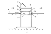
図1は本発明の海水交換防波堤の形態の一例であって、図1では本発明に係るケーソン本体1が海底の基礎マウンド2上に固定されており、更にケーソン本体1の上部には消波体3を備えた蓋体4が載置されている。
FIG. 1 shows an example of a seawater exchange breakwater according to the present invention. In FIG. 1, a
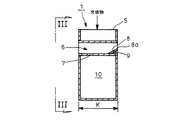
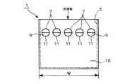
図2、図3は前記ケーソン本体の構成の一例を示すもので、ケーソン本体1は、コンクリートと鋼材からなるハイブリッド構造により所要の厚みKと幅Wを備えた略箱形を有しており、上部には開放された開口5を有している。更に、ケーソン本体1は、該ケーソン本体1を港湾の海底に設置した時の海水面L(平均潮位)に略一致する位置に消波部6を備えている。
2 and 3 show an example of the configuration of the caisson body, and the
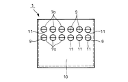
前記消波部6は、水平(海水面Lと平行)にケーソン本体1を厚みK方向に貫通する導水路7を備えており、図3では円筒状の導水路7がケーソン本体1の幅W方向に複数個(5個)設けられている。
The wave-dissipating
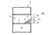
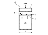
図4に示す如く、前記導水路7の内海側の内底部には、外海側から内海側に向かって上り傾斜の乗り越え傾斜面8を有する傾斜部材9を設けている。乗り越え傾斜面8の最も高くなっている乗り越え頂部8aは図1に示す如く海水面L(平均潮位)に略一致した高さになっている。図4において前記傾斜部材9の乗り越え頂部8aの上下方向高さT1は、導水路7の上下方向高さT2の略1/5〜1/2としており、また乗り越え傾斜面8の傾斜角度θは略10゜〜60゜としている。傾斜部材9は導水路7の内底面に溶接或いはボルト等にて固定するようにしている。
As shown in FIG. 4, an
図5は、図3の導水路7より小径とした円筒状の導水路7aをケーソン本体1に対して上下2段に設けた場合を示しており、潮位差がある程度大きい場合にはこのように複数段の導水路7aを設けることが有効である。
FIG. 5 shows a case where cylindrical
図1〜図5に示したケーソン本体1では、前記導水路7が設けられている部分以外の内部の全ては砂等の充填物を充填するための充填空間10となっている。
In the caisson
このとき、図3、図5の導水路7,7aは円筒状を有しているために、各導水路7,7aの下面には幅(図3、図5の左右方向幅)の中心部が最も大きく下方に突出し、これによって導水路7,7aの下側への充填物の回り込みを助けるようにした突出下面11が形成されており、導水路7,7aの下側へ砂等の充填物が回り込むことにより未充填部が生じるのを防止している。
At this time, since the
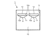
図6は導水路の他の形状例を示したもので、この導水路12は幅方向に細長い開口12aの下部に三角形状で下方に張り出した三角張り出し部12bを備えており、この三角張り出し部12bによって前記突出下面11が形成されている。この三角張り出し部12bの傾斜角度は砂等の安息角に略一致するように設定することが好ましい。そして、三角張り出し部12bの内部には傾斜部材9が設けられる。
FIG. 6 shows another example of the shape of the water conduit, and this
また、図7は導水路の更に他の形状例を示したもので、この導水路13は楕円形状を有しており、楕円形状の導水路13の下方に張り出した張り出し部13aによって前記突出下面11が形成されている。そして、張り出し部13aの内部には傾斜部材9が設けられる。
FIG. 7 shows still another example of the shape of the water conduit. The
また、図8は導水路の更に他の形状例を示したもので、この導水路14は、幅方向に細長い開口14aの下部に略半円形状で下方に張り出した半円張り出し部14bを備えており、この半円張り出し部14bによって前記突出下面11が形成されている。そして、半円張り出し部14bの内部には傾斜部材9が設けられる。
FIG. 8 shows still another example of the shape of the water conduit, and this
また、図9は導水路の更に他の形状例を示したもので、この導水路15は、1つの頂点15aが下方を向くようにした三角形状を有しており、この三角形状の頂点15aを挟む2辺によって前記突出下面11が形成されている。そして、三角形の導水路15の内側下部には傾斜部材9が設けられる。
FIG. 9 shows still another example of the shape of the water conduit, and this
また、図10は導水路の更に他の形状例を示したもので、この導水路16は、1つの頂点16aが下方を向くようにした三角形状を有しており、頂点16aを挟む鉛直面16bと傾斜辺16cとによって前記突出下面11が形成されている。そして、三角形の導水路16の内側下部には傾斜部材9が設けられる。
FIG. 10 shows still another example of the shape of the water conduit. The
前記図6〜図10においても導水路12,13,14,15,16の大きさ、設置数、設置段数等は任意に変更することができる。
6 to 10, the size, the number of installations, the number of installation stages, and the like of the
次に、上記図示例の作用を説明する。 Next, the operation of the illustrated example will be described.
図1〜図4、及び図5に示す如く、導水路7,7aを備えたケーソン本体1は工場等で製造する。このとき、前記ケーソン本体1の導水路7,7aには製造時に傾斜部材9を同時に取り付けるようにしてもよいが、傾斜部材9は後で取り付けるようにしてもよい。
As shown in FIGS. 1 to 4 and FIG. 5, the
前記ケーソン本体1は、ケーソン本体1の厚みK方向に導水路7,7aを貫通配置した簡略な構造であるため、製造が容易であり、しかもケーソン本体1に用いられる鋼材の重量を従来に比して大幅に低減することができる。更に、ケーソン本体1は、導水路7,7aが設けられている部分以外の全てを砂等の充填物を充填するための充填空間10とすることができる。
Since the
このように、前記ケーソン本体1は重量を軽量にできることと、充填空間10を大きくとれることから、前記ケーソン本体1を水に浮かべて曳航する際の浮力を大きくとることができ曳航のための喫水が上がる。従って、従来の如くケーソン本体の厚さ寸法を余分に増加する必要がなくなり、よってケーソン本体1の製造コストを大幅に低減することができる。
Thus, since the
更に、曳航時の喫水が上がるために、ケーソン本体1を小型にしても容易に曳航することができ、よって深度が浅い港湾等への設置も容易に可能になり、適用できる海域が大幅に拡大される。
Furthermore, since the draft at the time of towing increases, it is possible to easily tow even if the caisson
更に、ケーソン本体1の製造時には傾斜部材9を導水路7,7aに固定せずに、後で取り付けるようにすると、ケーソン本体1は厚さ方向の形状が全く同一になるために、厚さ方向の重量がバランスし、よって従来のようにカウンタウェイトを取り付ける必要がないので、このことによってもケーソン本体1の厚さ寸法を小さくすることができる。
Furthermore, when the caisson
前記ケーソン本体1を港湾の設置場所まで曳航した後、上部の開口5からケーソン本体1内部の充填空間10に砂等の充填物を投入することにより、充填物の重量によってケーソン本体1を沈下させ、図1に示すように基礎マウンド2上に設置する。
After towing the
このとき、図3、図5、図6〜図10に示した如く、前記導水路7,7a,12〜16の下面に、導水路7,7a,12〜16の下側への充填物の回り込みを助けるように下方に突出させた突出下面11を形成しているので、ケーソン本体1に充填物を投入してケーソン本体1を沈下させて海底に設置する際に、充填物は前記突出下面11に沿って導水路7,7a,12〜16の下側に回り込んで確実に充填されるようになる。従って、導水路7,7a,12〜16の下部に従来のような未充填部が生じることを防止でき、よって計画した通りのケーソン本体1の固定重量を得ることができる。上記において図3、図5、図6〜図9に示すように前記導水路7,7a,12〜15の幅方向中心部が最も大きく下方に突出した左右対象の突出下面11を形成すると、導水路7,7a,12〜15の下側に両側から充填物が回り込むことになるので好ましい。
At this time, as shown in FIGS. 3, 5, and 6 to 10, the filling material to the lower side of the
ケーソン本体1を現地で海底に設置する際に導水路7,7a,12〜16に傾斜部材9を固定するようにした場合には、傾斜部材9が比較的小型で軽量な構造を有しているので、溶接或いはボルト等によって容易に固定することができる。
When the
図11は本発明の海水交換防波堤の他の形態を示すものであって、図11では前記導水路7の内底部に、ケーソン本体1の厚みK方向に間隔をおいて複数の傾斜部材9を設けた場合を示している。尚、導水路7の内底部に設けられる傾斜部材9の設置数、設置位置は任意に変更することができる。
FIG. 11 shows another embodiment of the seawater exchange breakwater according to the present invention. In FIG. 11, a plurality of
前記ケーソン本体1を備えた図1の海水交換防波堤による作用を説明すると、外海からケーソン本体1に向かう波浪は、一部がケーソン本体1の前面壁に衝突して反射されるのみで、残りは導水路7の内部に導かれるので前面壁によって波浪が反射する波反射率は小さい。また、導水路7内に導入された波浪は、導水路7の内底部に設けた傾斜部材9の乗り越え傾斜面8に沿って上昇する際にその勢力が減衰されるので、傾斜部材9の乗り越え頂部8aを乗り越えて内海に流入する波浪の勢いは低下し、よって内海に対する波透過率も減少する効果がある。
The operation of the seawater exchange breakwater of FIG. 1 provided with the
更に、ケーソン本体1の導水路7内に導入された波浪は、平均潮位に略一致した乗り越え頂部8aを乗り越えて内海側に流入するようになるので、海水交換流量を高めることができる。即ち、乗り越え頂部8aが略平均潮位に一致しているので、波浪の高さが小さい時でも波浪は乗り越え頂部8aを乗り越えて内海側に流入することができ、よって波浪の高さに関係なく、常に良好な海水の交換作用を発揮することができる。
Furthermore, since the waves introduced into the
なお、本発明の海水交換防波堤は、上記した実施の形態に限定されるものではなく、本発明の要旨を逸脱しない範囲内において種々変更を加え得ることは勿論である。 The seawater exchange breakwater of the present invention is not limited to the above-described embodiment, and it is needless to say that various modifications can be made without departing from the scope of the present invention.
1 ケーソン本体
7,7a 導水路
8 乗り越え傾斜面
9 傾斜部材
10 充填空間
11 突出下面
12 導水路
13 導水路
14 導水路
15 導水路
16 導水路
DESCRIPTION OF
Claims (4)
Priority Applications (1)
| Application Number | Priority Date | Filing Date | Title |
|---|---|---|---|
| JP2004116814A JP2005299224A (en) | 2004-04-12 | 2004-04-12 | Seawater exchange breakwater |
Applications Claiming Priority (1)
| Application Number | Priority Date | Filing Date | Title |
|---|---|---|---|
| JP2004116814A JP2005299224A (en) | 2004-04-12 | 2004-04-12 | Seawater exchange breakwater |
Publications (1)
| Publication Number | Publication Date |
|---|---|
| JP2005299224A true JP2005299224A (en) | 2005-10-27 |
Family
ID=35331109
Family Applications (1)
| Application Number | Title | Priority Date | Filing Date |
|---|---|---|---|
| JP2004116814A Pending JP2005299224A (en) | 2004-04-12 | 2004-04-12 | Seawater exchange breakwater |
Country Status (1)
| Country | Link |
|---|---|
| JP (1) | JP2005299224A (en) |
Cited By (3)
| Publication number | Priority date | Publication date | Assignee | Title |
|---|---|---|---|---|
| JP2020143546A (en) * | 2019-03-08 | 2020-09-10 | 株式会社三井E&S鉄構エンジニアリング | L-type caisson structure |
| CN113585167A (en) * | 2019-07-06 | 2021-11-02 | 王建平 | Water-floating combined port and pier with steel-concrete structure |
| CN113653001A (en) * | 2021-09-01 | 2021-11-16 | 交通运输部天津水运工程科学研究所 | A slant-straight combined wave-proof caisson structure |
-
2004
- 2004-04-12 JP JP2004116814A patent/JP2005299224A/en active Pending
Cited By (4)
| Publication number | Priority date | Publication date | Assignee | Title |
|---|---|---|---|---|
| JP2020143546A (en) * | 2019-03-08 | 2020-09-10 | 株式会社三井E&S鉄構エンジニアリング | L-type caisson structure |
| JP7285392B2 (en) | 2019-03-08 | 2023-06-02 | 三井住友建設鉄構エンジニアリング株式会社 | L-shaped caisson structure |
| CN113585167A (en) * | 2019-07-06 | 2021-11-02 | 王建平 | Water-floating combined port and pier with steel-concrete structure |
| CN113653001A (en) * | 2021-09-01 | 2021-11-16 | 交通运输部天津水运工程科学研究所 | A slant-straight combined wave-proof caisson structure |
Similar Documents
| Publication | Publication Date | Title |
|---|---|---|
| US20130011197A1 (en) | Wave attenuation systems | |
| JP2005299224A (en) | Seawater exchange breakwater | |
| KR101403564B1 (en) | stabilization of the wave at the rear of the fixed-floating structure | |
| US8915672B2 (en) | Movable breakwater and method of operating movable breakwater | |
| JP5646978B2 (en) | Construction method of transmission type sea area control structure | |
| CN106368166A (en) | Semi-submersible wave dissipation device and wave dissipation method | |
| JPH0718641A (en) | Floating wave killing bank | |
| KR101352461B1 (en) | Breakwater caisson | |
| JP2006249914A (en) | Tidal wave breakwater | |
| JP4776694B2 (en) | Harbor structure and method for constructing such a structure | |
| JP4539989B2 (en) | Artificial seabed with upwelling flow and its construction method | |
| JPH06212611A (en) | Breakwater | |
| JPS62268410A (en) | Control system for tidal waves | |
| JP6749571B2 (en) | Tsunami attenuation groove structure | |
| JP2005207220A5 (en) | ||
| JP4229441B2 (en) | Artificial leaf with adjustable buoyancy | |
| KR100554612B1 (en) | Shore structure | |
| JP2006161371A (en) | Suspended curtain wall impermeable film assembly and its installation method | |
| JP2003096742A (en) | Seawater exchange breakwater caisson | |
| JP2010059705A (en) | Sea area control structure | |
| JPH03241111A (en) | Submerged breakwater | |
| EP1158103B1 (en) | Breakwater | |
| JP2579402B2 (en) | Air piston type squirting wavebreak structure and wavebreak structure using the same | |
| JP4519816B2 (en) | Seawall / breakwater | |
| KR100586636B1 (en) | Seawater exchange breakwater with ease of berthing |
Legal Events
| Date | Code | Title | Description |
|---|---|---|---|
| A621 | Written request for application examination |
Free format text: JAPANESE INTERMEDIATE CODE: A621 Effective date: 20070307 |
|
| A977 | Report on retrieval |
Free format text: JAPANESE INTERMEDIATE CODE: A971007 Effective date: 20080612 |
|
| A131 | Notification of reasons for refusal |
Free format text: JAPANESE INTERMEDIATE CODE: A131 Effective date: 20080701 |
|
| A02 | Decision of refusal |
Free format text: JAPANESE INTERMEDIATE CODE: A02 Effective date: 20081028 |
