JP2010059705A - Sea area control structure - Google Patents
Sea area control structure Download PDFInfo
- Publication number
- JP2010059705A JP2010059705A JP2008227185A JP2008227185A JP2010059705A JP 2010059705 A JP2010059705 A JP 2010059705A JP 2008227185 A JP2008227185 A JP 2008227185A JP 2008227185 A JP2008227185 A JP 2008227185A JP 2010059705 A JP2010059705 A JP 2010059705A
- Authority
- JP
- Japan
- Prior art keywords
- control structure
- area control
- block
- box
- sea area
- Prior art date
- Legal status (The legal status is an assumption and is not a legal conclusion. Google has not performed a legal analysis and makes no representation as to the accuracy of the status listed.)
- Granted
Links
- XLYOFNOQVPJJNP-UHFFFAOYSA-N water Substances O XLYOFNOQVPJJNP-UHFFFAOYSA-N 0.000 claims abstract description 50
- 230000005540 biological transmission Effects 0.000 claims description 22
- 230000000694 effects Effects 0.000 abstract description 27
- 230000006866 deterioration Effects 0.000 abstract description 4
- 229910000831 Steel Inorganic materials 0.000 description 24
- 239000010959 steel Substances 0.000 description 24
- 238000009434 installation Methods 0.000 description 14
- 238000005192 partition Methods 0.000 description 8
- 238000010276 construction Methods 0.000 description 7
- 239000002689 soil Substances 0.000 description 6
- 230000003628 erosive effect Effects 0.000 description 5
- 238000010030 laminating Methods 0.000 description 4
- 238000009991 scouring Methods 0.000 description 4
- 238000000926 separation method Methods 0.000 description 4
- 239000004568 cement Substances 0.000 description 3
- 239000003795 chemical substances by application Substances 0.000 description 3
- 239000000945 filler Substances 0.000 description 3
- 239000011440 grout Substances 0.000 description 3
- 238000000034 method Methods 0.000 description 3
- 239000004576 sand Substances 0.000 description 3
- 239000004575 stone Substances 0.000 description 3
- 238000002834 transmittance Methods 0.000 description 3
- 230000032258 transport Effects 0.000 description 3
- 238000010586 diagram Methods 0.000 description 2
- 230000007613 environmental effect Effects 0.000 description 1
- 230000002265 prevention Effects 0.000 description 1
Images


Abstract
Description
本発明は、海岸の侵食を防ぎ、また消波効果を得るために、海岸から沖側に所定距離離れた海底に海岸線に沿って配置される海域制御構造物に関するものである。なお、本発明の海域制御構造物は、水深10m〜20m程度の海底へ設置されるものである。 The present invention relates to a sea area control structure disposed along a coastline on the seabed at a predetermined distance from the coast to the offshore side in order to prevent coastal erosion and obtain a wave-dissipating effect. In addition, the sea area control structure of the present invention is installed on the seabed at a depth of about 10 m to 20 m.
従来から、海岸の侵食を防ぐ目的や消波効果を得るために、海岸から沖側に所定距離離れた海底には、海岸線に沿って海域制御構造物が配置される。 従来の海域制御構造物としては、主に以下に説明する(1)離岸堤、(2)人工リーフ、(3)有脚式離岸堤、(4)没水型離岸堤の構造方式が採用されているが、それぞれの構造方式に対して多くの課題が残されている。
(1)離岸堤は、水深が3m〜5mの海底に設置されるもので、主に異形ブロックを海岸線に沿って平行に積み上げた構造であり、長年に亘って侵食対策に多大な実績を残している。
しかしながら、この離岸堤は、天端面の高さを平均海面よりも十分に大きく(平均海面から突出する高さが1m〜2m)設定する必要があり、水面上の景観が良くない。しかも、ブロックの散乱等により漁業活動を阻害することがある。
(2)人工リーフは、水深が3m〜5mの海底に設置されるもので、主に石材を積層して天端幅(海岸線に直交する方向の幅)が広い潜堤構造(天端幅:50m〜100m)であり、没水構造であるために水面上の景観を阻害することはないが、漁業者等にとって天端が目視できず危険性があることから天端の水深を十分確保すると、天端幅をさらに広く設定する必要があり、建設コストの高騰につながる。しかも、人工リーフでは、高波浪が続くと、海岸線付近で平均水位が上昇する場合がある。
Conventionally, in order to prevent coastal erosion and to obtain a wave-dissipating effect, a sea area control structure is disposed along the coastline on the seabed a predetermined distance away from the coast. As the conventional sea area control structure, the structure method of (1) offshore breakwater, (2) artificial reef, (3) legged breakwater, (4) submerged breakwater, which will be explained below However, many problems remain for each structural method.
(1) The offshore dike is installed on the seabed with a water depth of 3m to 5m, and is mainly constructed by stacking deformed blocks in parallel along the coastline, and has a great track record in erosion countermeasures for many years. I'm leaving.
However, it is necessary to set the height of the top end surface sufficiently higher than the average sea level (the height protruding from the average sea level is 1 to 2 m), and the landscape on the water surface is not good. In addition, fishing activities may be hindered by block scattering.
(2) Artificial reefs are installed on the seabed with a water depth of 3m to 5m, and are mainly composed of stones and have a wide crest structure (width in the direction perpendicular to the coastline). 50m to 100m) and does not obstruct the landscape on the surface of the water because it is a submerged structure, but it is dangerous for fishers etc. because the top of the top cannot be visually observed and there is a danger, so Therefore, it is necessary to set the top width wider, leading to a rise in construction costs. Moreover, in the artificial reef, if high waves continue, the average water level may rise near the coastline.
(3)有脚式離岸堤は、水深が10m程度の海底に設置されるもので、ブロック体を複数の杭により海底に固定して構成されるもので、杭式構造で耐波安定性があり、最近では、所要の消波機能を有し、防災だけではなく環境面(海岸の侵食)、利用面(離岸距離の大)を併せて考慮すると、水深10m程度の海域には、この有脚式離岸堤が採用される場合もある。
しかしながら、この有脚式離岸堤もその天端面が平均海面よりも突出しているため、景観の是正が要求されている。また、有脚式離岸堤では、ブロック体を所定海域まで運搬するため、ブロック体の大きさに準じた起重機船を手配する必要があり、しかも、離岸堤に比べて設置水深が深くなりコストが高騰するため、コストの大幅な削減が要求されている。
(4)没水型離岸堤として柔構造潜堤(フレキシブルマウンド)が、ある地域で実用化されている。
しかしながら、この柔構造潜堤では、潮位差が大きい海域や海底勾配が急な海岸では
消波効果が低下したり、堤体規模が大きくなるほど現地への適用が困難になる場合がある。
(3) A legged breakwater is installed on the seabed with a water depth of about 10m, and is constructed by fixing the block body to the seabed with a plurality of piles. Yes, recently, it has the required wave-dissipating function, and considering not only disaster prevention but also environmental aspects (coastal erosion) and usage aspects (large separation distance), A legged breakwater may be used.
However, this legged breakwater also requires a correction of the landscape because its top edge protrudes beyond the average sea level. In addition, for a legged breakwater, it is necessary to arrange a hoisting ship according to the size of the block body in order to transport the block body to a predetermined sea area. Since the cost is soaring, significant cost reduction is required.
(4) Flexible submersibles (flexible mounds) have been put into practical use in certain areas as submerged breakwaters.
However, in this soft structure submerged dike, the wave-dissipation effect may be reduced in the sea area where the tide level difference is large or the coast where the seabed slope is steep, or the application to the site becomes more difficult as the size of the dike body increases.
なお、上述した(3)有脚式離岸堤の従来技術として特許文献1には、杭基礎に箱形の堤体が海底面との間に適宜間隙部をもって設置され、堤体は鉛直壁と傾斜壁とからなる前面壁、中間壁、後面壁、側面壁、底板および頂板からなり、鉛直壁および傾斜壁、中間壁、後面壁には透過スリットが開口され、底板および頂板には開口部が形成され、傾斜壁の透過スリットが中間壁の透過スリットよりも上部で、かつ中間壁の上部壁面に対向する箇所に開口された透過型海域制御構造物が開示されている。
上述した(1)〜(4)の構造方式では、海岸の侵食を防ぎ、所要の消波効果を得ることができるが、コスト高を抑制できず、しかも、水面上の景観が悪化し、さらには、漁業者等の船舶への配慮が欠けている。
また、上述した特許文献1の透過型海域制御構造物においても、平均海面から構造物の天端が突出しており、水面上の景観の悪化を是正することはできない。また、この特許文献1の透過型海域制御構造物では、特に、堤体に傾斜壁が形成され、コスト高の要因となっている。
In the structural methods (1) to (4) described above, coastal erosion can be prevented and the required wave-dissipating effect can be obtained, but the high cost cannot be suppressed, and the landscape on the water surface deteriorates. Lacks consideration for fishermen's ships.
Moreover, also in the transmission type sea area control structure of
本発明は、かかる点に鑑みてなされたものであり、所要の消波効果を得ると共に、コスト高を抑制し、しかも、水面上の景観の悪化を是正する海域制御構造物を提供することを目的とする。 This invention is made in view of this point, and while providing a required wave-dissipating effect, suppressing a high cost and providing the sea area control structure which corrects the deterioration of the landscape on the water surface. Objective.
本発明は、上記課題を解決するための手段として、請求項1に記載した発明は、海岸から離れた海底に、海岸線に沿って配置される海域制御構造物であって、該海域制御構造物は、内部が空洞化されると共に下方が開放される直方体で構成され、陸側壁部が海岸線に沿って配置される箱型ブロックと、該箱型ブロックと略同じ外形で、前記箱型ブロックの下方に配置される中空ブロックとが複数の杭によって海底に固定され、前記箱型ブロックの陸側壁部及び沖側壁部には透過スリットが形成されると共に、その天端壁部には開口部が形成され、また、前記箱型ブロックの天端壁部に平均海面から突出する突設部が形成されることを特徴とするものである。
請求項1の発明では、中空ブロック上に箱型ブロックを配置して複数の杭で海底に固定し、箱型ブロックの陸側壁部及び沖側壁部には透過スリットが形成されると共に、箱型ブロックの天端壁部に設けた突設部は平均海面から突出しているので所要の消波効果を得ることができ、しかも、箱型ブロックの天端壁部に設けた突設部を除く天端面は没水されているために、水面上の景観が是正される。
なお、箱型ブロックの天端壁部に設けた突設部は、消波効果の観点からは、天端壁部の陸側の端部に、天端壁部の海岸線に沿う一辺の全範囲に亘って連続して形成される方が好ましい。
また、請求項1の発明では、有脚構造としたので、水深10m〜20m程度(離岸距離が大)に設置する海域制御構造物として耐波安定性、消波効果及びコストの観点から最適である。
さらに、請求項1の発明では、箱型ブロックの下方に中空ブロックを配置しているので、箱型ブロック及び中空ブロックを適宜の大きさに抑制でき、これら箱型ブロック及び中空ブロックを設置海域まで運搬する起重機船に要するコストを削減することが可能になる。
The present invention provides, as means for solving the above-mentioned problems, the invention described in
In the invention of
In addition, the protruding portion provided on the top end wall portion of the box-shaped block is, from the viewpoint of the wave-dissipating effect, the entire range of one side along the coastline of the top end wall portion at the land side end of the top end wall portion. It is preferable to form continuously.
Further, in the invention of
Furthermore, in the invention of
請求項2に記載した発明は、請求項1に記載した発明において、前記中空ブロックの下方で、前記複数の杭が打設される箇所に土嚢がそれぞれ配設されることを特徴とするものである。
請求項2の発明では、各土嚢により中空ブロックを設置するための平坦な設置面を形成することができ、耐波安定性を向上させることができる。
The invention described in
In invention of
請求項3に記載した発明は、請求項1または2に記載した発明において、前記箱型ブロックの天端壁部に設けた前記突設部以外の天端面の平均海面からの水深と、前記突設部が平均海面から突出する高さとは略同じに設定されることを特徴とするものである。
請求項3の発明では、箱型ブロックの天端壁部に設けた突設部を除く天端面の平均海面からの水深と、箱型ブロックの天端壁部に設けた突設部が平均海面から突出する高さとは略同じに設定され、それらの値は消波対象波浪の有義波高の1/2程度に設定されているので、所要の消波効果を得ることができると共に、箱型ブロックの天端壁部に設けた突設部を除く天端面を水上から僅かに視認することができ、漁業者等により海域制御構造物の位置を認識することができる。
The invention described in
In invention of
請求項4に記載した発明は、請求項1〜3のいずれかに記載した発明において、前記各土嚢上に前記中空ブロックを設置した状態で、該中空ブロックの海底からの高さが水深に対して1/3〜1/2の所定値に設定されることを特徴とするものである。
請求項4の発明では、中空ブロックの高さが水深に対して1/3〜1/2の所定値に設定されるので、所要の消波効果を得ることができ、且つコストを最大限削減することができる。
The invention described in
In the invention of
請求項5に記載した発明は、請求項1に記載の発明において、前記中空ブロックの下方に捨石マウンドが備えられることを特徴とするものである。
請求項5の発明では、捨石マウンドにより中空ブロックを設置するための平坦な設置面を形成することができ、しかも、捨石マウンドにより杭周りの局所洗堀を防護することができる。
なお、捨石マウンド上に中空ブロックが設置された状態において、中空ブロックの海底からの高さは水深に対して1/3〜1/2の所定値に設定されるようにした方が好ましい。
The invention described in
In invention of
In the state where the hollow block is installed on the rubble mound, the height of the hollow block from the sea bottom is preferably set to a predetermined value of 1/3 to 1/2 with respect to the water depth.
請求項6に記載した発明は、海岸から離れた海底に、海岸線に沿って配置される海域制御構造物であって、該海域制御構造物は、内部が空洞化されると共に下方が開放される直方体で構成され、陸側壁部が海岸線に沿って配置される箱型ブロックが、該箱型ブロックの下方に配置される捨石マウンドを介して複数の杭によって海底に固定され、前記箱型ブロックの陸側壁部及び沖側壁部には透過スリットが形成されると共に、その天端壁部には開口部が形成され、また、前記箱型ブロックの天端壁部に平均海面から突出する突設部が形成されることを特徴とするものである。
請求項6の発明では、捨石マウンド上に箱型ブロックを配置し、箱型ブロックの陸側壁部及び沖側壁部に透過スリットが形成されると共に、箱型ブロックの天端壁部に平均海面から突出する突設部を設けているので所要の消波効果を得ることができ、しかも、箱型ブロックの天端壁部に設けた突設部を除く天端面は没水されているために、水面上の景観が是正される。
なお、箱型ブロックの天端壁部に設けた突設部は、消波効果の観点からは、天端壁部の陸側の端部に、天端壁部の海岸線に沿う一辺の全範囲に亘って連続して形成される方が好ましい。
また、請求項6の発明では、箱型ブロックの下方に捨石マウンドを配置しているので、箱型ブロックの大きさを適宜の大きさに抑制できるため、該箱型ブロックを設置海域まで運搬する起重機船に要するコストを削減することが可能になる。
さらに、請求項6の発明では、有脚構造としたので、水深10m〜20m程度(離岸距離が大)に設置する海域制御構造物として耐波安定性、消波効果及びコストの観点から最適である。しかも、捨石マウンドにより中空ブロックを設置するための平坦な設置面を形成することができ、さらには、捨石マウンドにより杭周りの局所洗堀を防護することができる。
The invention described in claim 6 is a sea area control structure disposed along the coastline on the seabed apart from the coast, and the sea area control structure is hollowed inside and opened downward. A box-shaped block composed of a rectangular parallelepiped and having a land wall portion disposed along the coastline is fixed to the sea floor by a plurality of piles via a rubble mound disposed below the box-shaped block. A transmission slit is formed in the land wall portion and the offshore wall portion, an opening is formed in the top end wall portion, and a projecting portion protruding from the average sea surface on the top end wall portion of the box-type block Is formed.
In the invention of claim 6, a box-shaped block is arranged on the rubble mound, a transmission slit is formed in the land wall portion and the offshore wall portion of the box-shaped block, and from the average sea surface to the top end wall portion of the box-shaped block. Since the protruding projecting part is provided, the required wave-breaking effect can be obtained, and the top end surface excluding the projecting part provided on the top end wall part of the box-type block is submerged, The landscape on the water surface is corrected.
In addition, the protruding portion provided on the top end wall portion of the box-shaped block is, from the viewpoint of the wave-dissipating effect, the entire range of one side along the coastline of the top end wall portion at the land side end of the top end wall portion. It is preferable to form continuously.
Moreover, in the invention of claim 6, since the rubble mound is arranged below the box-type block, the size of the box-type block can be suppressed to an appropriate size, and the box-type block is transported to the installation sea area. The cost required for the hoist ship can be reduced.
Furthermore, in the invention of claim 6, since it is a legged structure, it is optimal from the viewpoint of wave resistance stability, wave-dissipating effect and cost as a sea area control structure to be installed at a water depth of about 10m to 20m (large separation distance). is there. Moreover, a flat installation surface for installing the hollow block can be formed by the rubble mound, and further, local scouring around the pile can be protected by the rubble mound.
請求項7に記載した発明は、請求項6に記載した発明において、前記捨石マウンド内で前記複数の杭が打設される箇所にはそれぞれ土嚢が積層されることを特徴とするものである。
請求項7の発明では、複数の杭の打設が容易となる。
The invention described in claim 7 is characterized in that, in the invention described in claim 6, sandbags are respectively laminated at locations where the plurality of piles are driven in the rubble mound.
In the invention of claim 7, it becomes easy to place a plurality of piles.
請求項8に記載した発明は、請求項6または7に記載した発明において、前記箱型ブロックの天端壁部に設けた前記突設部以外の天端面の平均海面からの水深と、前記突設部が平均海面から突出する高さとは略同じに設定されることを特徴とするものである。
請求項8の発明では、箱型ブロックの天端壁部に設けた突設部を除く天端面の平均海面からの水深と、箱型ブロックの天端壁部に設けた突設部が平均海面から突出する高さとは略同じに設定され、それらの値は消波対象波浪の有義波高の1/2程度に設定されているので、所要の消波効果を得ることができると共に、箱型ブロックの天端壁部に設けた突設部を除く天端面を水上から僅かに視認することができ、漁業者等により海域制御構造物の位置を認識することができる。
The invention described in
In the invention of
請求項9に記載した発明は、請求項6〜8のいずれかに記載した発明において、前記捨石マウンドの海底からの高さは、水深に対して1/3〜1/2の所定値に設定されることを特徴とするものである。
請求項9の発明では、捨石マウンドの高さが水深に対して1/3〜1/2の所定値に設定されるので、所要の消波効果を得ることができ、且つコストを最大限削減することができる。
The invention described in
In the invention of
本発明によれば、所要の消波効果を得ることができ、しかも、箱型ブロックの突設部を除く天端面は没水されているために、水面上の景観が是正される。また、本発明は、水深10m〜20m程度に設置する海域制御構造物として最適である。
しかも、請求項1の発明では、箱型ブロックの下方に中空ブロックが配置され、一方、請求項6の発明では、箱型ブロックの下方に捨石マウンドが配置されているので、箱型ブロックや中空ブロックを設置海域まで運搬する起重機船に要するコストを大幅に削減することが可能になる。
According to the present invention, a required wave-dissipating effect can be obtained, and the top end surface excluding the protruding portion of the box-type block is submerged, so that the landscape on the water surface is corrected. The present invention is most suitable as a sea area control structure installed at a water depth of about 10 m to 20 m.
Moreover, in the invention of
以下、本発明を実施するための最良の形態を図1〜図12に基いて詳細に説明する。
まず、本発明の第1の実施形態に係る海域制御構造物1を図1〜図10に基いて説明する。
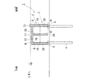
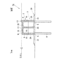
本発明の第1の実施形態に係る海域制御構造物1は、図1に示すように、内部が空洞化されると共に下方が開放される直方体で構成され、その陸側壁部8が海岸線に沿って配置される箱型ブロック2と、該箱型ブロック2と略同じ外形の直方体で形成され、箱型ブロック2の下方に配置される中空ブロック3と、該中空ブロック3の下方で鋼管杭4が打設される複数箇所(本実施の形態では6箇所)にそれぞれ、高さ方向に複数積層される土嚢5とから構成される。
Hereinafter, the best mode for carrying out the present invention will be described in detail with reference to FIGS.
First, the sea
As shown in FIG. 1, the sea
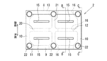
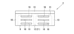
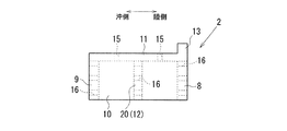
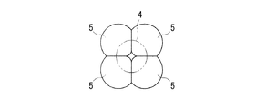
箱型ブロック2は、図1〜図5に示すように、コンクリートからなり、内部が空洞化されると共に下方を開放する直方体で構成される。この箱型ブロック2は、陸側に面する所定厚の陸側壁部8と、該陸側壁部8に対向して沖側に面する所定厚の沖側壁部9と、陸側壁部8と沖側壁部9とを一体的に接続する一対の側方壁部10、10と、陸側壁部8、沖側壁部9及び一対の側方壁部10、10の上端に一体的に接続される所定厚の天端壁部11とからなり、その内部に十字状の仕切壁部12が対応する陸側壁部8、沖側壁部9、各側方壁部10、10及び天端壁部11に一体的に接続されて、内部が4室に区画されている。
なお、箱型ブロック2の高さ(後述する突設部13を除く)は、本実施の形態では、水深10mに対して4.5mに設定されている。
As shown in FIGS. 1 to 5, the box-
In the present embodiment, the height of the box-shaped block 2 (excluding a protruding
天端壁部11は、図4及び図5に示す側面視でL字状に形成され、その陸側の端部に断面矩形状の突設部13が突設されている。この突設部13は、天端壁部11の海岸線に沿う長辺の全範囲に亘って連続して突設されている。また、この突設部13の高さは、箱型ブロック2が中空ブロック3上に設置された状態において、平均海面S.W.L.よりも突出する高さに設定されている。
そこで、図1に示すように、箱型ブロック2が中空ブロック3上に設置された状態において、該箱型ブロック2の天端壁部11に設けた突設部13以外の天端面Nの平均海面S.W.L.からの水深と、突設部13が平均海面S.W.L.から突出する高さとは略同じに設定され、本実施の形態では、水深10mに対して略50cmに設定されている。また、箱型ブロック2の天端壁部11に設けた突設部13の天端面Nからの高さは、本実施の形態では、水深10mに対して略1mに設定されており、つまり、箱型ブロック2は、天端壁部11に設けた突設部13の高さ方向略中間に平均海面S.W.L.が一致するように配置される。
なお、本実施の形態では、箱型ブロック2の天端壁部11に設けた突設部13以外の天端面Nの平均海面S.W.L.からの水深及び突設部13が平均海面S.W.L.から突出する高さは、それぞれ略50cmに設定されているが、それらの値は消波対象波浪の有義波高の1/2程度を目安に設定するようにしている。
The top
Therefore, as shown in FIG. 1, in the state where the box-shaped
In the present embodiment, the average sea surface S. of the top end surface N other than the projecting
また、本実施の形態では、突設部13は天端壁部11の陸側の端部に設けているが、必ずしも陸側の端部に設ける必要はなく、所要の消波効果を得ることができれば、沖側にやや寄った位置に設けてもよい。また、本実施の形態では、突設部13を天端壁部11の海岸線に沿う長辺の全範囲に亘って連続して設けているが、複数に分割して形成してもよい。
Moreover, in this Embodiment, although the
また、天端壁部11には、箱型ブロック2内の区画された4室の略中央にそれぞれ対応するように、陸側壁部8の長手方向に沿って延びる幅狭のスリット15(開口部)が形成されている。
Further, the top
陸側壁部8には、該陸側壁部8に面する箱型ブロック2内の各2室に対応するように、その上部、中間部及び下部のそれぞれにその長手方向に沿って延びる幅狭の透過スリット16が形成される。陸側壁部8には、全6個の透過スリット16が形成される。
沖側壁部9にも、該沖側壁部9に面する箱型ブロック2内の各2室に対応するように、その上部、中間部及び下部のそれぞれにその長手方向に沿って延びる幅狭の透過スリット16が形成される。沖側壁部9にも、全6個の透過スリット16が形成される。
また、十字状の仕切壁部12の内、陸側壁部8及び沖側壁部9と同じ方向に延びる一方の仕切壁部20にも、陸側壁部8及び沖側壁部9に設けた各透過スリット16と同じ位置に、且つ同じ形状の透過スリット16が形成される。
なお、本実施の形態では、陸側壁部8、沖側壁部9及び一方の仕切壁部20のそれぞれには、全6個の透過スリット16が所定位置に形成されているが、所要の消波効果を得るべく、各透過スリット16の開口幅、開口位置及び数量が適宜決定される。また、天端壁部11に設けた各スリット15は、箱型ブロック2への揚圧力の発生を防ぐために形成されたものであり、矩形状や円形状の開口部であってもよい。
The land
The offshore
In addition, each of the transmission slits provided in the
In the present embodiment, each of the
また、箱型ブロック2には、図2に示すように、平面視の4隅の部位と、陸側壁部8及び沖側壁部9と十字状の仕切壁部12の内他方の仕切壁部21とが接続される部位とに、鋼管杭4が挿入される杭用貫通孔22がそれぞれ形成され、杭用貫通孔22は全6孔形成される。
In addition, as shown in FIG. 2, the box-
中空ブロック3は、図1、図6〜図8に示すように、中空状で箱型ブロック2の外形と同じ直方体に形成され、箱型ブロック2と同様に、陸側に面する所定厚の陸側壁部25と、沖側に面する所定厚の沖側壁部26と、所定厚の一対の側方壁部27、27と、内部を4室に区画する所定厚の十字状の仕切壁部28とが一体的に接続されて構成されている。また、中空ブロック3には、箱型ブロック2に設けた各杭用貫通孔22と対応する位置に杭用貫通孔29がそれぞれ形成される。なお、本実施の形態では、中空ブロック3の高さは、水深10mに対して略4mに設定されている。
As shown in FIGS. 1 and 6 to 8, the
土嚢5は、図1に示すように、中空ブロック3の下方で鋼管杭4が打設される6箇所にそれぞれ、高さ方向に複数積層される。具体的には、図9に示すように、1本の鋼管杭4に対して、鋼管杭4の周りに4個の土嚢5を互いに接触するように配置して、且つ高さ方向に複数積層される。土嚢5は、土砂とセメントと分離防止剤とを混合させた処理土が袋詰めされて構成されており、鋼管杭4を打設できる程度の強度を有している。本実施の形態では、厚みが0.5m程度(長さ1m程度×幅1m程度)の大型土嚢が使用され、その強度は100kN /cm2相当である。
なお、図1に示すように、各土嚢5上に中空ブロック3を設置した状態において、中空ブロック3の海底からの高さが水深に対して1/3〜1/2の所定値に設定され、本実施の形態では、その高さは水深10mに対して略5m(各土嚢5の高さ略1m+中空ブロック3の高さ略4m)に設定されている。
As shown in FIG. 1, a plurality of
In addition, as shown in FIG. 1, in the state which installed the
次に、本発明の第1の実施形態に係る海域制御構造物1の構築方法を説明する。
まず、海岸から所定距離離れた海底に、土嚢5を、各鋼管杭4が打設される箇所にそれぞれ2層程度積層する。
次に、各土嚢5上に中空ブロック3及び箱型ブロック2を外形が一致するようにして、且つその陸側壁部8、25が陸側を向くように海岸線に沿って設置する。
次に、6本の鋼管杭4を箱型ブロック2及び中空ブロック3に設けた各杭用貫通孔22、29に挿通して、各土嚢5を介して海底に打設して、箱型ブロック2及び中空ブロック3を海底に固定する。
最後に、箱型ブロック2及び中空ブロック30の各杭用貫通孔22、29と、各鋼管杭4とのクリアランスに充填材としてのグラウトを充填する。さらに、各鋼管杭4内にはコンクリートが充填される。
なお、本実施の形態に係る海域制御構造物1は、箱型ブロック2及び中空ブロック3の陸側壁部8、25の長手方向(海岸線が延びる方向)の長さが略15mで形成されており、この箱型ブロック2が、その陸側壁部8が陸側を向くように海岸線に沿って複数個配列されて任意長さの海域制御構造物が構築される。
Next, the construction method of the sea
First, the
Next, the
Next, the six steel pipe piles 4 are inserted into the through
Finally, grout as a filler is filled in the clearance between the through
The sea
そして、第1の実施形態に係る海域制御構造物1の構築が完了すると、箱型ブロック2の天端壁部11に設けた突設部13が平均海面S.W.L.から突出する。本実施の形態では、該突設部13が平均海面S.W.L.から略50cm(消波対象波浪の有義波高の1/2程度)突出するようになる。
And if construction of the sea
なお、図10には、本発明の第1の実施形態に係る海域制御構造物1の消波効果を示しているが、本発明の第1の実施形態に係る海域制御構造物1では、H(波高)/L(波長)が0.05までの波に対して、KT(透過率)がその上限値(0.6)を越えることなく、また、KR(反射率)がその上限値(0.5)を超えることはなく、十分な消波機能を有していることが解る。
FIG. 10 shows the wave-dissipating effect of the sea
以上説明したように、本発明の第1の実施形態に係る海域制御構造物1では、箱型ブロック2の陸側壁部8、沖側壁部9及び仕切壁20のそれぞれに複数の透過スリット16が形成されると共に、箱型ブロック2の天端壁部11の陸側の端部に、天端壁部11の海岸線に沿う長辺の全範囲に亘って連続して突設された突設部13を設けて、該突設部13が、箱型ブロック2が中空ブロック3上に設置された状態において平均海面S.W.L.から消波対象波浪の有義波高の1/2程度突出しているので所要の消波効果を得ることができる。また、箱型ブロック2の天端壁部11の突設部13を除く天端面Nは没水されているために、水面上の景観が是正される。しかも、箱型ブロック2の天端壁部11にも複数のスリット15が形成されているので、箱型ブロック2への揚圧力の発生を防ぐことができる。
As described above, in the sea
また、第1の実施形態に係る海域制御構造物1は、箱型ブロック2の天端壁部11の突設部13を除く天端面Nの平均海面S.W.L.からの水深と、突設部13が平均海面S.W.L.から突出する高さとが略同じに設定され、その値は消波対象波浪の有義波高の1/2程度に設定されているので、所要の消波効果を得ることができると共に、箱型ブロック2の天端面Nを水上から僅かに視認することができ、漁業者等により海域制御構造物1の位置を認識することができる。
さらに、第1の実施形態に係る海域制御構造物1では、箱型ブロック2と、中空ブロック3と、各土嚢5とから構成されるので、箱型ブロック2や中空ブロック3の大きさを適宜の大きさに抑制でき、これら箱型ブロック2等を設置海域まで運搬する起重機船に要するコストを大幅に削減することできる。
さらにまた、第1の実施形態に係る海域制御構造物1では、各土嚢5により中空ブロック3を設置するための平坦な設置面を形成することができる。
In addition, the sea
Furthermore, since the sea
Furthermore, in the sea
そこで、中空ブロック3の設置面、すなわち、鋼管杭4を打設する海底の凹凸が激しく土嚢5の積層だけでは平坦な設置面を形成することができない場合には、予め、海底の凹部に第1の実施形態に係る海域制御構造物1で使用した土嚢5の処理土、すなわち、土砂とセメントと分離防止剤とを混合させた処理土を充填し、ある程度海底を平坦とした状態で土嚢5を積層した方がよい。
Therefore, when the installation surface of the
次に、本発明の第2の実施形態に係る海域制御構造物1aを図11に基いて説明する。
本発明の第2の実施形態に係る海域制御構造物1aは、図11に示すように、内部が空洞化されると共に下方が開放される直方体で構成され、その陸側壁部8が海岸線に沿って配置される箱型ブロック2と、該箱型ブロック2と略同じ外形の直方体で形成され、箱型ブロック2の下方に配置される中空ブロック3と、該中空ブロック3の下方に配置される捨石マウンド30とから構成される。
なお、本発明の第2の実施形態に係る海域制御構造物1aの箱型ブロック2及び中空ブロック3は、第1の実施形態に係る海域制御構造物1で採用された箱型ブロック2及び中空ブロック3と同一であるためここでの説明を省略する。
Next, a sea
As shown in FIG. 11, the sea
The box-
捨石マウンド30は、図11に示すように、50〜200kg/個程度の基礎捨石31を積層して形成されている。捨石マウンド30の高さは、本実施の形態では、水深10mに対して略1mに設定されている。
捨石マウンド30内で、鋼管杭4が打設される6箇所には、第1の実施形態に係る海域制御構造物1で採用された土嚢5が複数積層されている。
なお、図11に示すように、捨石マウンド30上に中空ブロック3を設置した状態において、中空ブロック3の海底からの高さは水深に対して1/3〜1/2の所定値に設定され、本実施の形態では、その高さは水深10mに対して略5m(捨石マウンド30の高さ略1m+中空ブロック3の高さ略4m)に設定されている。
As shown in FIG. 11, the
In the
In addition, as shown in FIG. 11, in the state which installed the
次に、本発明の第2の実施形態に係る海域制御構造物1aの構築方法を説明する。
まず、海岸から所定距離離れた海底に、土嚢5を、各鋼管杭4が打設される箇所にそれぞれ2層程度積層した後、各土嚢5の周りに基礎捨石31を積層して、上述したような捨石マウンド30を形成する。
次に、捨石マウンド30上に中空ブロック3及び箱型ブロック2を外形が一致するようにして、且つその陸側壁部8、25が陸側を向くように海岸線に沿って設置する。
次に、6本の鋼管杭4を箱型ブロック2及び中空ブロック3に設けた各杭用貫通孔22、29に挿通して、捨石マウンド30(土嚢5)を介して海底に打設する。
最後に、箱型ブロック2及び中空ブロック3の各杭用貫通孔22、29と、各鋼管杭14とのクリアランスに充填材としてのグラウトを充填する。さらに、各鋼管杭4内にはコンクリートが充填される。
Next, the construction method of the sea
First, the
Next, the
Next, the six steel pipe piles 4 are inserted into the through
Finally, grout as a filler is filled in the clearances between the through
そして、第2の実施形態に係る海域制御構造物1aの構築が完了すると、第1の実施形態に係る海域制御構造物1と同様に、箱型ブロック2の天端壁部11に設けた突設部13が平均海面S.W.L.から突出する。本実施の形態では、該突設部13が平均海面S.W.L.から略50cm(消波対象波浪の有義波高の1/2程度)突出するようになる。
And if construction of the sea
なお、本発明の第2の実施形態に係る海域制御構造物1aにおいても、第1の実施形態に係る海域制御構造物1と同様に、H(波高)/L(波長)が0.05までの波に対して、KT(透過率)がその上限値(0.6)を越えることなく、また、KR(反射率)がその上限値(0.5)を超えることはなく、十分な消波機能を有している。
In the sea
以上説明したように、本発明の第2の実施形態に係る海域制御構造物1aでは、本発明の第1の実施形態に係る海域制御構造物1と同様の消波効果が得られ、しかも、箱型ブロック2の天端面Nを水上から僅かに視認することができ、漁業者等により海域制御構造物1bの位置を認識することができる。
また、第2の実施形態に係る海域制御構造物1aでは、捨石マウンド30を採用しているので、消波効果を向上させると共に、中空ブロック3の設置のための平坦な設置面を形成することができ、しかも、各鋼管杭4の打設による局所洗掘を防護することもできる。
As described above, in the sea
Moreover, in the sea
なお、第2の実施形態に係る海域制御構造物1aにおいて、中空ブロック3の下方に設置された捨石マウンド30を複数のブロックに分割して、ブロック毎に網体(フトン籠)で包んで構成してもよい。これにより、基礎捨石31の飛散を防ぐことができ、魚網等の損傷を防ぐことができる。
さらに、第2の実施形態に係る海域制御構造物1aにおいて採用した捨石マウンド30に代わって、第1及び第2の実施形態に係る海域制御構造物1、1aで使用した土嚢5の処理土、すなわち、土砂とセメントと分離防止剤とを混合させた処理土を積層してマウンドを形成してもよい。この形態の場合には、第2の実施形態において、鋼管杭4が打設される6箇所に積層した土嚢5は必要としない。
In addition, in the sea
Furthermore, instead of the
次に、本発明の第3の実施形態に係る海域制御構造物1bを図12に基いて説明する。
本発明の第3の実施形態に係る海域制御構造物1bは、図12に示すように、内部が空洞化されると共に下方が開放される直方体で構成され、陸側壁部8が海岸線に沿って配置される箱型ブロック2と、該箱型ブロック2の下方に配置される捨石マウンド33とから構成される。
なお、本発明の第3の実施形態に係る海域制御構造物1bの箱型ブロック2は、第1及び第2の実施形態に係る海域制御構造物1、1aで採用された箱型ブロック2と同一であるためここでの説明を省略する。
Next, a sea area control structure 1b according to a third embodiment of the present invention will be described with reference to FIG.
As shown in FIG. 12, the sea area control structure 1b according to the third embodiment of the present invention is configured by a rectangular parallelepiped whose inside is hollowed and whose lower side is opened, and the
The box-
捨石マウンド33は、図12に示すように、海底からの高さが水深に対して1/3〜1/2の所定値に設定され、本実施の形態では、水深10mに対してその高さは略5mに設定されている。
捨石マウンド33は、50〜200kg/個程度の基礎捨石31を積層して形成されており、沖側の傾斜面には1t/個の被覆石34が傾斜面に沿って複数配列されている。
また、捨石マウンド33内で、鋼管杭4が打設される6箇所には、第1及び第2の実施形態に係る海域制御構造物1、1aで採用した土嚢5が複数積層されている。
As shown in FIG. 12, the
The
In addition, a plurality of
次に、本発明の第3の実施形態に係る海域制御構造物1bの構築方法を説明する。
まず、海岸から所定距離離れた海底に、土嚢5を、各鋼管杭4が打設される箇所にそれぞれ2層程度積層した後に、各土嚢5の周りに基礎捨石31を積層し、この工程を4、5回程度繰り返して上述したような捨石マウンド33を形成する。
次に、捨石マウンド33上に箱型ブロック2をその陸側壁部8が陸側を向くように海岸線に沿って設置する。
次に、各鋼管杭4を箱型ブロック2に設けた各杭用貫通孔22に挿通して、捨石マウンド33(土嚢5)を介して海底に打設する。その後、箱型ブロック2の各杭用貫通孔22と鋼管杭4とのクリアランスに充填材としてのグラウトが充填される。さらに、各鋼管杭4内にはコンクリートが充填される。
Next, the construction method of the sea area control structure 1b according to the third embodiment of the present invention will be described.
First, after laminating about 2 layers of
Next, the box-shaped
Next, each
そして、第3の実施形態に係る海域制御構造物1bの構築が完了すると、第1及び第2の実施形態に係る海域制御構造物1、1aと同様に、箱型ブロック2の天端壁部11に設けた突設部13が平均海面S.W.L.から突出する。本実施の形態では、該突設部13が平均海面S.W.L.から略50cm(消波対象波浪の有義波高の1/2程度)突出するようになる。
And if construction of the sea area control structure 1b which concerns on 3rd Embodiment is completed, the top end wall part of the box-
なお、本発明の第3の実施形態に係る海域制御構造物1bにおいても、第1及び第2の実施形態に係る海域制御構造物1、1aと同様に、H(波高)/L(波長)が0.05までの波に対して、KT(透過率)がその上限値(0.6)を越えることなく、また、KR(反射率)がその上限値(0.5)を超えることはなく、十分な消波機能を有している。
In addition, in the sea area control structure 1b according to the third embodiment of the present invention, as in the sea
以上説明したように、本発明の第3の実施形態に係る海域制御構造物1bでは、本発明の第1及び第2の実施形態に係る海域制御構造物1、1aと同様の消波効果が得られ、しかも、箱型ブロック2の天端面Nを水上から僅かに視認することができ、漁業者等により海域制御構造物1bの位置を認識することができる。
また、第3の実施形態に係る海域制御構造物1bでは、捨石マウンド33を採用しているので、消波効果を向上させると共に、箱型ブロック2の設置のための平坦な設置面を形成することができ、しかも、各鋼管杭4の打設による局所洗掘を防護することもできる。
As described above, the sea area control structure 1b according to the third embodiment of the present invention has the same wave-dissipating effect as the sea
Moreover, in the sea area control structure 1b which concerns on 3rd Embodiment, since the
1、1a、1b 海域制御構造物,2 箱型ブロック,3 中空ブロック,4 鋼管杭(杭),5 土嚢,8 陸側壁部,9 沖側壁部,11 天端壁部,13 突設部,15 スリット(開口部),16 透過スリット 30、33 捨石マウンド,N 天端面 1, 1a, 1b Sea area control structure, 2 box-type block, 3 hollow block, 4 steel pipe pile (pile), 5 sandbag, 8 land side wall part, 9 offshore side wall part, 11 top end wall part, 13 projecting part, 15 slit (opening), 16 transmission slit 30, 33 rubble mound, N top end face
Claims (9)
該海域制御構造物は、内部が空洞化されると共に下方が開放される直方体で構成され、陸側壁部が海岸線に沿って配置される箱型ブロックと、該箱型ブロックと略同じ外形で、前記箱型ブロックの下方に配置される中空ブロックとが複数の杭によって海底に固定され、
前記箱型ブロックの陸側壁部及び沖側壁部には透過スリットが形成されると共に、その天端壁部には開口部が形成され、また、前記箱型ブロックの天端壁部に平均海面から突出する突設部が形成されることを特徴とする海域制御構造物。 A sea area control structure arranged along the coastline on the sea floor away from the coast,
The sea area control structure is configured by a rectangular parallelepiped whose inside is hollowed and the lower part is opened, and a land block is disposed along the coastline, and has substantially the same outer shape as the box block, The hollow block disposed below the box-shaped block is fixed to the sea floor by a plurality of piles,
A transmission slit is formed in the land wall portion and the offshore wall portion of the box block, and an opening is formed in the top end wall portion thereof. A sea area control structure characterized in that a projecting projecting portion is formed.
該海域制御構造物は、内部が空洞化されると共に下方が開放される直方体で構成され、陸側壁部が海岸線に沿って配置される箱型ブロックが、該箱型ブロックの下方に配置される捨石マウンドを介して複数の杭によって海底に固定され、
前記箱型ブロックの陸側壁部及び沖側壁部には透過スリットが形成されると共に、その天端壁部には開口部が形成され、また、前記箱型ブロックの天端壁部に平均海面から突出する突設部が形成されることを特徴とする海域制御構造物。 A sea area control structure arranged along the coastline on the sea floor away from the coast,
The sea area control structure is configured by a rectangular parallelepiped whose inside is hollowed out and opened downward, and a box block whose land side wall is disposed along the coastline is disposed below the box block. Fixed to the sea floor by multiple piles through a rubble mound,
A transmission slit is formed in the land wall portion and the offshore wall portion of the box block, and an opening is formed in the top end wall portion thereof. A sea area control structure characterized in that a projecting projecting portion is formed.
Priority Applications (1)
| Application Number | Priority Date | Filing Date | Title |
|---|---|---|---|
| JP2008227185A JP5234415B2 (en) | 2008-09-04 | 2008-09-04 | Sea area control structure |
Applications Claiming Priority (1)
| Application Number | Priority Date | Filing Date | Title |
|---|---|---|---|
| JP2008227185A JP5234415B2 (en) | 2008-09-04 | 2008-09-04 | Sea area control structure |
Publications (2)
| Publication Number | Publication Date |
|---|---|
| JP2010059705A true JP2010059705A (en) | 2010-03-18 |
| JP5234415B2 JP5234415B2 (en) | 2013-07-10 |
Family
ID=42186793
Family Applications (1)
| Application Number | Title | Priority Date | Filing Date |
|---|---|---|---|
| JP2008227185A Active JP5234415B2 (en) | 2008-09-04 | 2008-09-04 | Sea area control structure |
Country Status (1)
| Country | Link |
|---|---|
| JP (1) | JP5234415B2 (en) |
Cited By (1)
| Publication number | Priority date | Publication date | Assignee | Title |
|---|---|---|---|---|
| JP2011169077A (en) * | 2010-02-22 | 2011-09-01 | Toyo Constr Co Ltd | Sea area controlling structure and construction method thereof |
Families Citing this family (1)
| Publication number | Priority date | Publication date | Assignee | Title |
|---|---|---|---|---|
| CN106192882B (en) * | 2016-08-24 | 2019-01-04 | 中交水运规划设计院有限公司 | Two-way cross transmission combination form system |
Citations (2)
| Publication number | Priority date | Publication date | Assignee | Title |
|---|---|---|---|---|
| JPH01190809A (en) * | 1988-01-26 | 1989-07-31 | Hazama Gumi Ltd | Wave elimination device |
| JPH08193315A (en) * | 1995-01-13 | 1996-07-30 | Fujita Corp | Breakwater |
-
2008
- 2008-09-04 JP JP2008227185A patent/JP5234415B2/en active Active
Patent Citations (2)
| Publication number | Priority date | Publication date | Assignee | Title |
|---|---|---|---|---|
| JPH01190809A (en) * | 1988-01-26 | 1989-07-31 | Hazama Gumi Ltd | Wave elimination device |
| JPH08193315A (en) * | 1995-01-13 | 1996-07-30 | Fujita Corp | Breakwater |
Cited By (1)
| Publication number | Priority date | Publication date | Assignee | Title |
|---|---|---|---|---|
| JP2011169077A (en) * | 2010-02-22 | 2011-09-01 | Toyo Constr Co Ltd | Sea area controlling structure and construction method thereof |
Also Published As
| Publication number | Publication date |
|---|---|
| JP5234415B2 (en) | 2013-07-10 |
Similar Documents
| Publication | Publication Date | Title |
|---|---|---|
| US10400406B2 (en) | Wave dissipation systems, modules and methods for constructing the same | |
| JP2007262890A (en) | Structure for controlling permeable sea area and construction method thereof | |
| JP2006241806A (en) | Tsunami breakwater | |
| JP5234415B2 (en) | Sea area control structure | |
| CN201952778U (en) | Breakwater | |
| JP2002309539A (en) | Artificial beach nourishment structure and sand barrier for harbor | |
| JP7285392B2 (en) | L-shaped caisson structure | |
| KR102025654B1 (en) | Submerged breakwater type fish reef | |
| US9683346B2 (en) | Perforated structure mountable onto a seabed | |
| JP5872797B2 (en) | High stability type breakwater | |
| KR200201513Y1 (en) | Breakwater circulating seawater | |
| US20120051845A1 (en) | Deep water port | |
| US20150010364A1 (en) | Deep-water port | |
| JP2006125102A (en) | Block for shore | |
| JP4719310B1 (en) | Revetment structure | |
| JP2520363B2 (en) | Sloping bank | |
| JP5656143B2 (en) | Construction method of sea area control structure | |
| JP2014202016A (en) | Reinforcement structure of caisson type hybrid bank and construction method of reinforcement structure | |
| JP5818955B2 (en) | Sea area control structure | |
| KR102383735B1 (en) | Caisson connection structure and construction method for tidal level difference | |
| KR200408221Y1 (en) | Revetment institution for pro-environment | |
| JP4413719B2 (en) | Submarine | |
| KR100654304B1 (en) | Revetment institution for pro-environment | |
| JP2001115429A (en) | Environment-friendly breakwater | |
| EP3384095A1 (en) | Perforated structure mountable onto a seabed |
Legal Events
| Date | Code | Title | Description |
|---|---|---|---|
| A621 | Written request for application examination |
Free format text: JAPANESE INTERMEDIATE CODE: A621 Effective date: 20110704 |
|
| A977 | Report on retrieval |
Free format text: JAPANESE INTERMEDIATE CODE: A971007 Effective date: 20120727 |
|
| TRDD | Decision of grant or rejection written | ||
| A01 | Written decision to grant a patent or to grant a registration (utility model) |
Free format text: JAPANESE INTERMEDIATE CODE: A01 Effective date: 20130306 |
|
| A61 | First payment of annual fees (during grant procedure) |
Free format text: JAPANESE INTERMEDIATE CODE: A61 Effective date: 20130314 |
|
| R150 | Certificate of patent or registration of utility model |
Free format text: JAPANESE INTERMEDIATE CODE: R150 Ref document number: 5234415 Country of ref document: JP Free format text: JAPANESE INTERMEDIATE CODE: R150 |
|
| FPAY | Renewal fee payment (event date is renewal date of database) |
Free format text: PAYMENT UNTIL: 20160405 Year of fee payment: 3 |
|
| R250 | Receipt of annual fees |
Free format text: JAPANESE INTERMEDIATE CODE: R250 |
|
| R250 | Receipt of annual fees |
Free format text: JAPANESE INTERMEDIATE CODE: R250 |
|
| R250 | Receipt of annual fees |
Free format text: JAPANESE INTERMEDIATE CODE: R250 |
|
| R250 | Receipt of annual fees |
Free format text: JAPANESE INTERMEDIATE CODE: R250 |
|
| R250 | Receipt of annual fees |
Free format text: JAPANESE INTERMEDIATE CODE: R250 |
|
| R250 | Receipt of annual fees |
Free format text: JAPANESE INTERMEDIATE CODE: R250 |
|
| R250 | Receipt of annual fees |
Free format text: JAPANESE INTERMEDIATE CODE: R250 |