JP2005299110A - Traveling sleeper judgment device - Google Patents
Traveling sleeper judgment device Download PDFInfo
- Publication number
- JP2005299110A JP2005299110A JP2004113150A JP2004113150A JP2005299110A JP 2005299110 A JP2005299110 A JP 2005299110A JP 2004113150 A JP2004113150 A JP 2004113150A JP 2004113150 A JP2004113150 A JP 2004113150A JP 2005299110 A JP2005299110 A JP 2005299110A
- Authority
- JP
- Japan
- Prior art keywords
- lateral pressure
- traveling
- pressure loading
- sleeper
- rail
- Prior art date
- Legal status (The legal status is an assumption and is not a legal conclusion. Google has not performed a legal analysis and makes no representation as to the accuracy of the status listed.)
- Granted
Links
Images


Landscapes
- Machines For Laying And Maintaining Railways (AREA)
Abstract
【課題】 レールに規定の横圧を連続的に付与した状態で軌道レール上を走行させ、測定の安全を確保しながら軌間の変位量をデータ処理部で計算し、マクラギのレールに対する支持力の強弱を判断することでマクラギの劣化の判定を自動的に効率よく行い、信頼性の高いマクラギの管理を実施する走行式マクラギ判定装置を提供する。
【解決手段】 走行しながらレール軌間方向に連続的に横圧力をかけ、その際の軌間の変位量を測定する走行式マクラギ判定装置において、横圧載荷部はその主要部を構成する円筒管33のレール接触部に横圧載荷ローラ31、31’を使用し、固定側横圧載荷部ガイド部を中心にして円筒管33に回動力を付与して横圧載荷ローラ31、31’の回転軸を垂直面内において走行台車1の進行方向に関して下向きに傾斜させる脱輪防止装置を横圧載荷部の可動側横圧載荷部ガイド部35’に設けた走行式マクラギ判定装置。
【選択図】 図1
PROBLEM TO BE SOLVED: To calculate the amount of displacement between gauges in a data processing unit while ensuring the safety of measurement while traveling on a track rail with a specified lateral pressure continuously applied to the rail, and to determine the support force of sleepers on the rail. Provided is a traveling sleeper determination device that automatically and efficiently determines sleeper deterioration by determining strength and performs highly reliable sleeper management.
In a traveling type sleeper determination apparatus that continuously applies lateral pressure in the direction between rails while traveling and measures the amount of displacement between the rails at that time, the lateral pressure loading part is a cylindrical tube 33 constituting the main part thereof. The lateral pressure loading rollers 31 and 31 'are used for the rail contact portion of the rail, and rotational force is applied to the cylindrical tube 33 around the fixed lateral pressure loading portion guide portion to rotate the rotation shaft of the lateral pressure loading rollers 31 and 31'. Is a traveling sleeper determination device in which a derailment prevention device that tilts downward in the vertical plane with respect to the traveling direction of the traveling carriage 1 is provided on the movable lateral pressure loading portion guide portion 35 'of the lateral pressure loading portion.
[Selection] Figure 1
Description
この発明は、軌道上を走行させることで、マクラギの良否を定量的に把握する走行式マクラギ判定装置に関する。 The present invention relates to a traveling sleeper determination apparatus that quantitatively grasps the quality of sleepers by traveling on a track.
木製マクラギは腐朽が進行すると犬釘の支持力が低下し、これによって、レール支持力の不足により軌間が拡がるという重大事故につながる恐れがある。
このため従来は検査員が目視と、打撃音等によってマクラギの交換が必要か否かを判断している。
このような検査者の経験による判定に頼らず測定を行う方法として、「マクラギ判定装
置」を使用する方法があり、部分的に使用されている(特許文献1 参照)。
これは、油圧ジャッキと油圧ポンプと油圧測定器と油圧ジャッキの変位量を計測する変位測定器によって構成されており、測定個所に固定して測定を行う。
When wooden sleepers decay, the bearing capacity of the dog nail decreases, which may lead to a serious accident in which the gap between the rails increases due to insufficient rail bearing capacity.
For this reason, in the past, an inspector has determined whether or not sleepers need to be replaced by visual inspection, impact sound, or the like.
As a method of performing measurement without relying on the determination based on the experience of such an inspector, there is a method using a “sleeper determination device”, which is partially used (see Patent Document 1).
This is composed of a hydraulic jack, a hydraulic pump, a hydraulic measuring instrument, and a displacement measuring instrument that measures the displacement amount of the hydraulic jack, and performs measurement while being fixed to a measurement location.
この装置により、レール間に外向きに向かう横圧を与えることができる。与えた横圧によりレール軌間が拡大するため、この拡がり変位量を測定する。この拡がり変位量が所定値以上に達する地点では、マクラギのレールに対する支持力が弱いことが解り、マクラギの劣化を知ることができる。
従来の検査員の経験と勘に頼る検査方法では、検査者の技量の差により個人差が生まれ、不良マクラギの判定にバラツキがあった。特に、表面上腐朽した様子に見えないマクラギが内部で腐朽が進んでいることもあり、これを見抜くことは困難なことである。
また、従来の装置は、各測定点に装置を固定し測定を行う方怯であることから、測定数が多いと作業に多大な時間を必要としている。
このようなことから、列車走行と同様に軌道上を走行させながら連続的に測定を行い、より正確な測定を行うことができ、しかも作業性の向上が計れるマクラギ判定装置の早期開発が望まれていた。
In the conventional inspection methods that rely on the experience and intuition of the inspector, individual differences were caused by differences in the skills of the inspectors, and there was variation in the determination of defective sleepers. In particular, sleepers that do not appear to decay on the surface are decaying inside, making it difficult to see through.
Moreover, since the conventional apparatus is a method of measuring by fixing the apparatus to each measurement point, if the number of measurements is large, a long time is required for work.
For this reason, early development of a sleeper determination device that can perform continuous measurement while traveling on a track in the same way as train traveling, can perform more accurate measurement, and can improve workability is desired. It was.
請求項1:走行台車上に横圧載荷部およぴ軌間変位測定部を配置し、走行しながらレール軌間方向に連続的に横圧力をかけ、その際の軌間の変位量を測定する走行式マクラギ判定装置を構成した。
そして、請求項2:請求項1に記載される走行式マクラギ判定装置において、横圧載荷部はその主要部を構成する円筒管33のレール接触部に横圧載荷ローラ31、31’を使用し、固定側横圧載荷部ガイド部を中心にして円筒管33に回動力を付与して横圧載荷ローラ31、31’の回転軸を垂直面内において走行台車1の進行方向に関して下向きに傾斜させる脱輪防止装置を横圧載荷部の可動側横圧載荷部ガイド部35’に設けた走行式マクラギ判定装置を構成した。
[Claim 1] A traveling type in which a lateral pressure loading section and a gauge displacement measuring section are arranged on a traveling carriage, and a lateral pressure is continuously applied in a rail gauge direction while traveling, and a displacement amount between the gauges is measured at that time. A sleeper determination device was constructed.
Further, in the traveling type sleeper determination apparatus according to
この発明によれば、データ測定処理部を走行台車に搭載し、レールに規定の横圧を連続的に付与した状態で軌道レール上を走行させ、測定の安全を確保しながら軌間の変位量をデータ処理部で計算し、マクラギのレールに対する支持力の強弱を判断することでマクラギの劣化の判定を自動的に効率よく行い、信頼性の高いマクラギの管理を実施することができる。 According to the present invention, the data measurement processing unit is mounted on the traveling carriage, and the rail is traveled on the track rail in a state where the prescribed lateral pressure is continuously applied to the rail, and the displacement amount between the rails is measured while ensuring the safety of the measurement. By calculating in the data processing unit and determining the strength of the support of the sleeper rail, it is possible to automatically and efficiently determine the sleeper deterioration, and to carry out highly reliable sleeper management.
走行式マクラギ判定装置は、走行台車部とデータ処理部とで構成し、走行台車をレール上で走行させることで、各測定個所のマクラギの良否を定量的に把握することができる。
発明を実施するための最良の形態を図1ないし図4を参照して具体的に説明する。
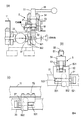
先ず、図1を参照して走行式マクラギ判定装置の概略を説明する。
走行台車1は、後で詳しく説明されるが、4輪式として測定時の走行安定性を確保している。走行台車1の中央部には、レールに直角の方向に延伸して走行台車フレーム11が形成されている。走行台車フレーム11はステンレス板をチャンネル形状にして製作し、強度を持たせると共に軽量化を図っている。この走行台車フレーム11の中間部には、固定側横圧載荷部ガイド部35と可動側横圧載荷部ガイド部35’の対が対向して2対取り付け固定されており、これらにより横圧載荷部3は保持、案内される。ここで、31は横圧載荷部3の固定側横圧載荷ローラ、31’は可動側横圧載荷ローラであり、横圧載荷部3は、固定側横圧載荷ローラ31および可動側横圧載荷ローラ31’を介して両レール間を突っ張る構成を採用してレールに横圧を載荷する。走行台車フレーム11には、1組の軌間センサ6、6’も設置されている。走行台車フレーム11は、脱輪時に横圧載荷部3が軌間外に飛び出すのを防止する作用も果たし、作業員等への安全性を確保している。
The traveling sleeper determination apparatus includes a traveling carriage unit and a data processing unit, and allows the traveling carriage to travel on the rail, thereby quantitatively grasping sleepiness at each measurement location.
The best mode for carrying out the invention will be described in detail with reference to FIGS.
First, an outline of the traveling sleeper determination device will be described with reference to FIG.
As will be described in detail later, the traveling cart 1 is a four-wheeled type that ensures traveling stability during measurement. A traveling
図2を参照して走行台車の走行車輪2の形状および走行車輪部20を説明する。走行台車1の走行車輪2の踏面形状は、脱輪防止対策としてフラット形状としている。これは走行車輪2の踏面形状が通常のテーパ形状の場合、レールとの接触点がレール頭面方向へ変化し易く、車輪が乗り上げ、脱輸が起こり易くなるのを防止するためである。
図3をも参照して横圧載荷部3を説明する。横圧載荷部3は、上述した通り、走行台車フレーム11の中間部に対向して固定側横圧載荷部ガイド部35と可動側横圧載荷部ガイド部35’の対が対向して2対取り付け固定されおり、これにより保持、案内される。横圧載荷部3には、更に、横圧載荷除荷装置4が付設されると共に、可動側横圧載荷部ガイド部35’には脱輪防止装置5が内在付設されている。横圧載荷部3としては、油圧シリンダ、油圧ポンプおよび制御部より成る油圧方武を採用することもできるが、図示される実施例は操作性を重視し、小型軽量化する観点からスプリング方式を採用している。スプリングとしてコイルスプリング32を使用し、横圧載荷部3が固定側横圧載荷ローラ31および可動側横圧載荷ローラ31’を介して両レール間を突っ張る構成を採用してレールに横圧を載荷するものとしている。
The shape of the
The lateral
横圧載荷部3は、コイルスプリング32を収納する円筒管33を主要部としている。円筒管33は、その一方の端部が円筒管33と一体形成した横圧載荷部固定部30に支持されると共に、他方の端部が直動スプライン34を用いた直線運動する横圧載荷部可動部30’で支持されている。横圧載荷部3の主要部を構成する円筒管33は、横圧載荷部固定部30の固定側横圧載荷ローラ31と横圧載荷部可動部30’の可動側横圧載荷ローラ31’により、走行台車1とは無関係に両レール間を突っ張る構成とされて、軌間狂いの変化に追従させることができる。横圧載荷部3とレールとの間には、加圧接触した際の走行時の抵抗を少なくする観点からも、固定側横圧載荷ローラ31および可動側横圧載荷ローラ31’が使用される。
The lateral
次いで、横圧載荷除荷装置4について説明する。横圧載荷除荷装置4は手動式油圧制御による。この横圧載荷除荷装置4は、走行台車1上に配置される油圧ポンプ41、横圧載荷部3の上部に配置される油圧引きシリンダ42およびピストン43、連結パイプ44より成る。図示される状態の横圧載荷除荷装置4は、油が油圧引きシリンダ42から油圧ポンプ41に連結パイプ44を介して排出されて、円筒管33内に収納されるコイルスプリング32が直動スプライン34を介して横圧載荷部可動部30’を強くバイアスして可動側横圧載荷ローラ31’をレールの側面に圧接した状態にある。油圧ポンプ41を動作させ、油圧引きシリンダ42に連結パイプ44を介して油を注入すると、この油圧によりピストン43は左方に駆動され、これによりコイルスプリング32のバイアスに抗して可動側横圧載荷ローラ31’を図において左方に変位し、可動側横圧載荷ローラ31’をレールの側面から開放して横圧は除荷される。
Next, the lateral pressure loading / unloading device 4 will be described. The lateral pressure unloading device 4 is based on manual hydraulic control. The lateral pressure loading / unloading device 4 includes a
図4を参照して脱輪防止装置5を説明する。横圧載荷による軌間の変位は、レール底部側面と犬釘との狭間によりレール全体が軌間外方へ変位した場合と、レールが軌間外方へ傾いた場合に生じる。レールが軌間外方へ傾いて生じた変位の場合は、レール頭側面の横圧載荷ローラ31、31’接触面に乗り上げ方向への傾斜角θが発生する。測定時における横圧載荷ローラ31、31’のレール乗り上がりに起因する走行台車1のレールへの乗り上がりを防止するに、横圧載荷部3に脱輪防止装置5を設けた。この脱輪防止装置5は、横圧載荷部3の固定側横圧載荷ローラ31の回転軸および可動側横圧載荷ローラ31’の回転軸を、垂直面内において走行台車1の進行方向に関して下向きに傾斜角θに対応して傾斜させることにより、上述の走行車輪2の乗り上げを防止するものである。以下、脱輪防止装置を具体的に説明する。
With reference to FIG. 4, the
脱輪防止装置5は、可動側横圧載荷部ガイド部35’に付設され、駆動部材51、上下変位部材52、固定制限部材53、抑え部材54、クランプレバー55を組み合わせることにより構成される。上下変位部材52には、雌ネジ孔Fが形成されており、このネジ孔Fには雄ネジMがネジ切りされた駆動部材51が螺合している。固定制限部材53は、上下変位部材52をその案内部531において上下方向にガイドすると共に、走行台車フレーム11ヘの固定、駆動部材51の上下方向の可動量を制限する制限部材として動作する。ここで、駆動部材51の上下方向の可動量が傾斜角θを補償する傾き量となる。抑え部材54は固定制限部材53に固定され、上下変位部材52を上下に変位させない役割を果たしている。上下変位部材52には、その上部に水平方向に延伸してクランプレバー55が具備されている。そして、上下変位部材52の下部には水平横孔521が貫通形成されると共に、この水平横孔521に連通して水平ガイドローラ501収容部522が形成され、水平ガイドローラ501が軸支されている。更に、この上下変位部材52には、水平横孔521の上側および下側に垂直ガイドローラ502が対向して軸支されている。ここで、37はガイドローラ係合部材であり、円筒管33に固着して水平に延伸している。このガイドローラ係合部材37は、その水平部を水平横孔521に進入して垂直ガイドローラ502間を通過し、水平ガイドローラ501に接触係合している。
The
ここで、クランプレバー55を水平面内において操作して駆動部材51を回転させると、上下変位部材52は案内部531内において固定制限部材53および抑え部材54により上下動を制限されているので、駆動部材51は回転のみをすることになり、上下変位部材52は駆動部材51の雄ネジ部Mの案内により可動量範囲で上下駆動されることになる。上下変位部材52が上下駆動されることにより、この駆動力は接触する垂直ガイドローラ502を介してガイドローラ係合部材37に加えられ、円筒管33は可動側横圧載荷部ガイド部35’側において上向きに押し上げられ或いは下向きに押し下げられる。他方の固定側横圧載荷部ガイド部35は走行台車フレーム11に固定されているのでフレーム11に関して上下方向に変位しないが、一方の可動側横圧載荷部ガイド部35’はクランプレバー55の操作により上下に変位することとなる。これにより、横圧載荷部3の主要部を構成する円筒管33は、走行台車フレーム11に上下方向に関して変位しない2個の固定側横圧載荷部ガイド部35により保持される一方、2個の可動側横圧載荷部ガイド部35’は上下方向に駆動されて、円筒管33を自身の軸方向に関して回動する回動力が発生する。横圧載荷部3の円筒管33が回動することにより円筒管33を支持する横圧載荷部可動部30’も回動し、横圧載荷部可動部30’に具備される可動側横圧載荷ローラ31’の回転軸は垂直面内において走行台車1の進行方向に関して下向きに傾斜角θに対応して傾斜せしめられる。この時、円筒管33を支持する横圧載荷部固定部30の固定側横圧載荷ローラ31も、同様に、その回転軸は垂直面内において走行台車1の進行方向に関して下向きに傾斜角θに対応して傾斜せしめられる。可動側横圧載荷ローラ31’の回転軸と固定側横圧載荷ローラ31の回転軸の双方が走行台車1の進行方向に関して下向きに傾斜せしめられることにより、両ローラ31、31’には走行台車フレーム11を介して走行台車1から下向きの車重の成分が加わるに到る。この成分が、レール頭側面のローラ接触面に乗り上げ方向への傾斜角が発生したことに起因する走行台車1の走行車輪2の乗り上がりの傾向を緩和し、その脱輪を防止することにつながる。
Here, when the driving
ここで、軌間センサ6について説明する。軌間センサ6は、レールレベルから16mm以内の軌間最短距離を測定するセンサであり、直動スプラインと変位センサで構成している。この軌間センサ6は走行台車1上に取り付けられ、左右レールに対称の位置で1組配置している。各軌間センサ6は、走行台車1の基準位置とレール間の距離を測定し、軌間狂い量を算出する。
そして、距離センサ7について説明するに、これは走行車輪2の回転数を距離検知センサによりカウントし、各測定点および走行距離を求める構成を有している。
Here, the gauge sensor 6 will be described. The gauge sensor 6 is a sensor that measures the shortest gauge distance within 16 mm from the rail level, and includes a linear motion spline and a displacement sensor. This gauge sensor 6 is mounted on the traveling carriage 1, and one set is arranged at positions symmetrical to the left and right rails. Each gauge sensor 6 measures the distance between the reference position of the traveling carriage 1 and the rails, and calculates the gauge deviation amount.
Then, the
データ処理部8について説明するに、これは変換器とパソコンにより構成し、0.5m毎に各センサの入力処理を行い、ハードディスク内にデータを記憶するものである。このデータ処理部8は、走行台車1に脱着式で搭載する構成とされている。各軌間センサ6による測定中、記憶したデータを処理し、パソコン上に以下のものを表示する。
・測点番号 0.5mを1測点とし表示。
・軌間センサ測定値 各センサの測定値を表示。
・動的軌間量 各軌間センサ測定値を加算した値を表示。
・静的軌間量 静的軌間量(手測り測定値等)を手入力。
・軌間拡大量 動的軌間量−静的軌間量の計算結果を表示。
The data processing unit 8 will be described. The data processing unit 8 is constituted by a converter and a personal computer, performs input processing of each sensor every 0.5 m, and stores data in the hard disk. The data processing unit 8 is configured to be detachably mounted on the traveling carriage 1. During the measurement by each gauge sensor 6, the stored data is processed and the following is displayed on the personal computer.
-Station number 0.5m is displayed as 1 station.
-Gauge sensor measurement value Displays the measurement value of each sensor.
-Dynamic gauge amount Displays the value obtained by adding each gauge sensor measurement value.
・ Static gauge amount Manually input the static gauge amount (hand measurement value, etc.).
-Gauge expansion amount Displays the calculation result of the dynamic gauge amount-static gauge amount.
以上の通りであって、この発明によれぱ、データ測定処理部を走行台車に搭載し、レールに規定の横圧を連続的に付与した状態で軌道レール上を走行させ、安全を確保しつつ軌間の変位量を測定することができ、この軌間の変位量をデータ処理部で計算し、マクラギのレールに対する支持力の強弱を判断することでマクラギの劣化の判定を自動で行うことができる。 As described above, according to the present invention, the data measurement processing unit is mounted on the traveling carriage, and the vehicle is driven on the track rail in a state where the prescribed lateral pressure is continuously applied to the rail, while ensuring safety. The displacement amount between the rails can be measured, and the displacement amount between the rails is calculated by the data processing unit, and the deterioration of sleepers can be automatically determined by determining the strength of the support force of the sleepers with respect to the rails.
この発明によれば、データ処理部は、各センサの入力を行う変換器と測定データを随時記憶するパソコンにより構成され、検査中にデータ処理を行うことができる。
軌間変位量(拡大量)は、載荷時の軌間測定データと無載荷時の軌間測定データとの比較により算出される。そのために、無載荷状態で軌間測定を行うか或いは他の測定器により測定したデータをパソコンに入力しておき、基本データとして使用することで、変位量の算出を行うことができる。動的軌間量を基準値と比較することで、マクラギの不良箇所を判定し、測定時に警報を発生させる機能を設けることもできる。
According to this invention, the data processing unit is configured by the converter that inputs each sensor and the personal computer that stores the measurement data as needed, and can perform data processing during the inspection.
The gauge displacement (enlarged quantity) is calculated by comparing the gauge measurement data at the time of loading with the gauge measurement data at the time of no loading. For this purpose, the displacement amount can be calculated by performing gauge measurement in a no-load state or inputting data measured by another measuring instrument into a personal computer and using it as basic data. By comparing the dynamic gauge amount with a reference value, it is also possible to provide a function of determining a sleeper defective portion and generating an alarm at the time of measurement.
1 走行台車 11 走行台車フレーム
2 走行車輪 20 走行車輪部
3 横圧載荷部 30 横圧載荷部固定部
30’横圧載荷部可動部 31 固定側横圧載荷ローラ
31’可動側横圧載荷ローラ 32 コイルスプリング
33 円筒管 34 直動スプライン
35 固定側横圧載荷部ガイド部 35’可動側横圧載荷部ガイド部
36 ガイドローラ受け部 37 ガイドローラ係合部材
4 横圧載荷除荷装置 41 油圧ポンプ
42 油圧引きシリンダ 43 ピストン
44 連結パイプ 5 脱輪防止装置
501 水平ガイドローラ 502 垂直ガイドローラ
51 駆動部材 52 上下変位部材
521 水平横孔 522 水平ガイドローラ収容部
53 固定制限部材 54 抑え部材
55 クランプレバー 6 軌間センサ
7 距離センサ 8 データ処理部
F 雌ネジ M 雄ネジ
θ 傾斜角
DESCRIPTION OF SYMBOLS 1
Claims (2)
横圧載荷部はその主要部を構成する円筒管のレール接触部に横圧載荷ローラを使用し、固定側横圧載荷部ガイド部を中心にして円筒管に回動力を付与して横圧載荷ローラの回転軸を垂直面内において走行台車の進行方向に関して下向きに傾斜させる脱輪防止装置を横圧載荷部の可動側横圧載荷部ガイド部に設けたことを特徴とする走行式マクラギ判定装置。
In the traveling sleeper determination device according to claim 1,
The lateral pressure loading part uses a lateral pressure loading roller at the rail contact part of the cylindrical tube that constitutes its main part, and applies a rotational force to the cylindrical pipe around the fixed side lateral pressure loading part guide part to obtain the lateral pressure loading. A traveling sleeper determination device, characterized in that a derailment prevention device for tilting the rotating shaft of the roller downward in the vertical plane with respect to the traveling direction of the traveling carriage is provided in the movable lateral pressure loading portion guide portion of the lateral pressure loading portion. .
Priority Applications (1)
| Application Number | Priority Date | Filing Date | Title |
|---|---|---|---|
| JP2004113150A JP4094578B2 (en) | 2004-04-07 | 2004-04-07 | Traveling sleeper judgment device |
Applications Claiming Priority (1)
| Application Number | Priority Date | Filing Date | Title |
|---|---|---|---|
| JP2004113150A JP4094578B2 (en) | 2004-04-07 | 2004-04-07 | Traveling sleeper judgment device |
Publications (2)
| Publication Number | Publication Date |
|---|---|
| JP2005299110A true JP2005299110A (en) | 2005-10-27 |
| JP4094578B2 JP4094578B2 (en) | 2008-06-04 |
Family
ID=35330994
Family Applications (1)
| Application Number | Title | Priority Date | Filing Date |
|---|---|---|---|
| JP2004113150A Expired - Fee Related JP4094578B2 (en) | 2004-04-07 | 2004-04-07 | Traveling sleeper judgment device |
Country Status (1)
| Country | Link |
|---|---|
| JP (1) | JP4094578B2 (en) |
Cited By (7)
| Publication number | Priority date | Publication date | Assignee | Title |
|---|---|---|---|---|
| RU2334840C1 (en) * | 2007-04-19 | 2008-09-27 | Открытое акционерное общество Калужский завод "Ремпутьмаш" | Method of supervisory control of railway position and device for its implementation |
| JP2018062241A (en) * | 2016-10-12 | 2018-04-19 | 株式会社ダイフク | Rail inspection device and rail inspection system |
| CN108458863A (en) * | 2018-03-22 | 2018-08-28 | 中南大学 | The longitudinally reciprocal loading simulation experimental provision of track |
| RU2667055C1 (en) * | 2017-06-07 | 2018-09-13 | Открытое Акционерное Общество "Российские Железные Дороги" | Areas with unstable track gauge detection method and device for its implementation |
| CN111749063A (en) * | 2020-07-17 | 2020-10-09 | 江西日月明测控科技股份有限公司 | A rail inspection mechanism and rail inspection trolley |
| CN113894824A (en) * | 2021-12-09 | 2022-01-07 | 浙江高信技术股份有限公司 | Track inspection robot |
| JP2023532795A (en) * | 2020-07-09 | 2023-07-31 | プラッサー ウント トイラー エクスポート フォン バーンバウマシーネン ゲゼルシャフト ミット ベシュレンクテル ハフツング | Machine and method for compacting track ballast bed |
-
2004
- 2004-04-07 JP JP2004113150A patent/JP4094578B2/en not_active Expired - Fee Related
Cited By (12)
| Publication number | Priority date | Publication date | Assignee | Title |
|---|---|---|---|---|
| RU2334840C1 (en) * | 2007-04-19 | 2008-09-27 | Открытое акционерное общество Калужский завод "Ремпутьмаш" | Method of supervisory control of railway position and device for its implementation |
| JP2018062241A (en) * | 2016-10-12 | 2018-04-19 | 株式会社ダイフク | Rail inspection device and rail inspection system |
| US10604899B2 (en) | 2016-10-12 | 2020-03-31 | Daifuku Co., Ltd. | Rail inspection device and rail inspection system |
| TWI798186B (en) * | 2016-10-12 | 2023-04-11 | 日商大福股份有限公司 | Rail inspection device and rail inspection system |
| RU2667055C1 (en) * | 2017-06-07 | 2018-09-13 | Открытое Акционерное Общество "Российские Железные Дороги" | Areas with unstable track gauge detection method and device for its implementation |
| CN108458863A (en) * | 2018-03-22 | 2018-08-28 | 中南大学 | The longitudinally reciprocal loading simulation experimental provision of track |
| CN108458863B (en) * | 2018-03-22 | 2023-12-22 | 中南大学 | Rail longitudinal reciprocating loading simulation experiment device |
| JP2023532795A (en) * | 2020-07-09 | 2023-07-31 | プラッサー ウント トイラー エクスポート フォン バーンバウマシーネン ゲゼルシャフト ミット ベシュレンクテル ハフツング | Machine and method for compacting track ballast bed |
| JP7753331B2 (en) | 2020-07-09 | 2025-10-14 | プラッサー ウント トイラー エクスポート フォン バーンバウマシーネン ゲゼルシャフト ミット ベシュレンクテル ハフツング | Machine and method for compacting the ballast bed of a track |
| CN111749063A (en) * | 2020-07-17 | 2020-10-09 | 江西日月明测控科技股份有限公司 | A rail inspection mechanism and rail inspection trolley |
| CN113894824A (en) * | 2021-12-09 | 2022-01-07 | 浙江高信技术股份有限公司 | Track inspection robot |
| CN113894824B (en) * | 2021-12-09 | 2022-03-08 | 浙江高信技术股份有限公司 | Track inspection robot |
Also Published As
| Publication number | Publication date |
|---|---|
| JP4094578B2 (en) | 2008-06-04 |
Similar Documents
| Publication | Publication Date | Title |
|---|---|---|
| CN107270860B (en) | Device and method for evaluating wheel alignment of a vehicle | |
| CN112832077B (en) | Railway rail center detection vehicle | |
| JP4094578B2 (en) | Traveling sleeper judgment device | |
| CN201600215U (en) | Force measuring wheel set static calibration test bench | |
| JPH08210950A (en) | Non-contact tester for railway rolling-stock wheel | |
| CN107255545A (en) | Calibration test platform for force-measuring wheel set | |
| CN101657585A (en) | Method and machine for lowering tracks | |
| CZ2012125A3 (en) | Test bench for stationary testing rail vehicles and measuring method on such a test bench | |
| KR101732352B1 (en) | Horizontal bearing post test device for guard rail post | |
| ITPI20130072A1 (en) | MEASUREMENT SYSTEM OF BRAKING FORCE OF A VEHICLE | |
| US20090000133A1 (en) | Toe Angle Measuring Instrument and Toe Angle Measuring Method | |
| CN112832078B (en) | A railway line center inspection vehicle | |
| CN106855461A (en) | For the test device of parking and braking mechanism | |
| CN215329097U (en) | A railway line center inspection vehicle | |
| KR102247101B1 (en) | W/L Calibration Device | |
| CN210968543U (en) | Verticality detection device | |
| CN119779183A (en) | An intelligent monitoring method for rock deformation around the entire tunnel | |
| KR200216177Y1 (en) | Wheel Wear Measurement Gauge | |
| CN219624702U (en) | Rock climbing fulcrum abrasion detection device | |
| JP2627873B2 (en) | Inspection equipment for dump truck load testing mechanism | |
| JPS62135712A (en) | Wheel measuring instrument for railway rolling stock | |
| KR100797341B1 (en) | Rail width measuring device | |
| CN216684424U (en) | Vehicle is examined to automatic digital display rail in herringbone combination rail center | |
| CN223407920U (en) | Measuring vehicle for installing tunnel emergency evacuation platform | |
| CN115420362B (en) | A Non-Physical Dynamic Calibration Method for Dynamic Truck Scales |
Legal Events
| Date | Code | Title | Description |
|---|---|---|---|
| A621 | Written request for application examination |
Free format text: JAPANESE INTERMEDIATE CODE: A621 Effective date: 20061121 |
|
| A977 | Report on retrieval |
Free format text: JAPANESE INTERMEDIATE CODE: A971007 Effective date: 20071102 |
|
| A131 | Notification of reasons for refusal |
Effective date: 20071106 Free format text: JAPANESE INTERMEDIATE CODE: A131 |
|
| A521 | Written amendment |
Effective date: 20071226 Free format text: JAPANESE INTERMEDIATE CODE: A523 |
|
| RD03 | Notification of appointment of power of attorney |
Effective date: 20071226 Free format text: JAPANESE INTERMEDIATE CODE: A7423 |
|
| A521 | Written amendment |
Free format text: JAPANESE INTERMEDIATE CODE: A821 Effective date: 20071226 |
|
| TRDD | Decision of grant or rejection written | ||
| A01 | Written decision to grant a patent or to grant a registration (utility model) |
Free format text: JAPANESE INTERMEDIATE CODE: A01 Effective date: 20080226 |
|
| A61 | First payment of annual fees (during grant procedure) |
Free format text: JAPANESE INTERMEDIATE CODE: A61 Effective date: 20080305 |
|
| FPAY | Renewal fee payment (prs date is renewal date of database) |
Year of fee payment: 3 Free format text: PAYMENT UNTIL: 20110314 |
|
| R150 | Certificate of patent (=grant) or registration of utility model |
Free format text: JAPANESE INTERMEDIATE CODE: R150 |
|
| LAPS | Cancellation because of no payment of annual fees |