JP2005298941A - Continuous annealing temperature control method for steel sheet - Google Patents
Continuous annealing temperature control method for steel sheet Download PDFInfo
- Publication number
- JP2005298941A JP2005298941A JP2004119888A JP2004119888A JP2005298941A JP 2005298941 A JP2005298941 A JP 2005298941A JP 2004119888 A JP2004119888 A JP 2004119888A JP 2004119888 A JP2004119888 A JP 2004119888A JP 2005298941 A JP2005298941 A JP 2005298941A
- Authority
- JP
- Japan
- Prior art keywords
- temperature
- furnace
- equipment
- plate temperature
- continuous annealing
- Prior art date
- Legal status (The legal status is an assumption and is not a legal conclusion. Google has not performed a legal analysis and makes no representation as to the accuracy of the status listed.)
- Pending
Links
Images


Landscapes
- Control Of Heat Treatment Processes (AREA)
- Heat Treatment Of Strip Materials And Filament Materials (AREA)
Abstract
【課題】 先行材と後行材との焼鈍条件変更部や操業定常状態において発生しうる板温基準からの外れ代を最小にすることのできる鋼板の連続焼鈍板温制御方法を提供する。
【解決手段】 ガス加熱式の連続焼鈍炉における鋼板の連続焼鈍方法において、なんらかの要因で鋼板の加熱負荷を変化させるにあたり、既存の応答性の遅い炉で発生する条件変更部分の目標板温からの外れを低減させる為に、予測した設備出側板温と通板速度、鋼板サイズその他の操業条件より導出する入口投入熱量残存率(昇温率)より、設備入口の応答性の早い設備で加熱に必要となる鋼板温度変更量に変換し、加熱条件の変更に必要な投入熱量として応答性の早い設備に設定することを特徴とする。
【選択図】 図3
PROBLEM TO BE SOLVED: To provide a continuous annealing plate temperature control method for a steel sheet capable of minimizing a deviation margin from a plate temperature reference that may occur in an annealing condition changing portion between a preceding material and a following material or in a steady operation state.
In a continuous annealing method of a steel plate in a gas heating type continuous annealing furnace, when changing the heating load of the steel plate due to some factor, from the target plate temperature of the condition change portion generated in an existing slow-responsive furnace. In order to reduce the detachment, heating is performed with equipment with quick response at the equipment inlet, based on the estimated temperature at the outlet side of the equipment, through-plate speed, steel sheet size and other residual heat input rate (temperature rise rate) derived from other operating conditions. It converts into the required steel plate temperature change amount, and is set to the equipment with quick responsiveness as input heat amount required for the change of heating conditions.
[Selection] Figure 3
Description
本発明は鋼板の連続焼鈍炉による鋼板の焼鈍における板温制御方法において、先行材と後行材との焼鈍条件変更部や操業定常状態において発生しうる板温基準からの外れ代を最小にする板温制御方法に関するものである。 The present invention minimizes the deviation from the sheet temperature reference that may occur in the annealing condition change part of the preceding material and the succeeding material and the steady state of operation in the sheet temperature control method in the annealing of the steel sheet by the continuous annealing furnace of the steel sheet. The present invention relates to a plate temperature control method.
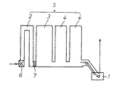
図1に示すようなメッキセクションを持ち、前段部より無酸化炉(NOF)と還元炉(RTF)3と冷却炉(CF)4とを直列に配置したガス加熱式の連続焼鈍炉5において、鋼板は無酸化炉2で例えば常温状態から600 ℃前後まで加熱され、還元炉3ではさらに700 ℃前後に加熱される加熱パターンを目標加熱パターンとして選択することがある。
In a gas heating type continuous annealing
図1に示すような連続焼鈍炉5では鋼板は常に炉内を移動しており、通板されるコイルのサイズ、鋼種も様々であり、諸般の操業条件から同一コイル通板中においても炉内通板速度の変更が日常的に発生してきている。このような連続焼鈍炉の操業条件変更が発生した場合でも、前述した目標加熱パターンを守るために無酸化炉2や還元炉3のガス流量を調整することにより目標温度からの外れを少なくするように各炉の出側実績板温を用いたフィードバック制御を実施している。
In the continuous annealing
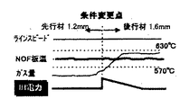
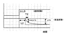
例えば、図2は板厚が1.2mm の先行材から1.6mm の後行材に鋼板が変化する時の無酸化炉2の状態を示したグラフである。後行材は先行材よりも板厚が厚いので、例えば、先行材、後行材で無酸化炉の目標板温が同じだとすると、ガス流量を増加させねばならず、図6に示したような、ガス流量変更に対する鋼板温度の応答性を考慮すると、先行材の終端部よりガス量を増加させる必要がある。この場合、先行材終端部で板温管理範囲外高めはずれ、後行材先端部で板温管理範囲外低めはずれが発生していた。
先行材と後行材において板厚、目標加熱パターンなどの条件が変更する場合に、先行材終端部から後行材先端部にかけての鋼板温度の管理範囲はずれ部位を最小にすることはもとより、定常状態において応答性の遅い炉の既存制御で抑制できなかった鋼板温度の管理範囲はずれ部位を最小にする連続焼鈍炉鋼板温度制御方法を提供するものである。 When conditions such as plate thickness and target heating pattern change between the preceding material and the succeeding material, the control range of the steel sheet temperature from the leading material end to the following material leading end is not only minimized, but also the steady state The present invention provides a continuous annealing furnace steel plate temperature control method that minimizes the deviation region of the steel plate temperature that could not be suppressed by existing control of a slow-responsive furnace in the state.
本発明は、ガス加熱式の連続焼鈍炉における鋼板の連続焼鈍方法において、鋼板サイズ、加熱パターン、通板速度変更などの要因で鋼板の加熱負荷を変化させるにあたり、既存の応答性の遅い炉で発生する条件変更部分の目標板温からの外れを低減させる為に、予測した設備出側板温と通板速度、鋼板サイズなどの操業条件より導出する入口投入熱量残存率(昇温率)より、設備入口の応答性の早い設備で加熱に必要となる鋼板温度変更量に変換し、加熱条件の変更に必要な投入熱量として応答性の早い設備に設定することを特徴としている。 In the continuous annealing method of a steel sheet in a gas heating type continuous annealing furnace, the present invention is an existing slow-responsive furnace for changing the heating load of a steel sheet due to factors such as a change in the steel sheet size, heating pattern, and plate passing speed. In order to reduce the deviation from the target plate temperature of the condition change part that occurs, from the estimated facility outlet side plate temperature, the plate passing speed, the residual rate of input heat amount (temperature increase rate) derived from the operating conditions such as plate size, It is characterized in that it is converted into a steel plate temperature change amount required for heating in equipment with quick response at the equipment entrance, and is set in the equipment with quick response as the input heat amount required for changing the heating conditions.
また、直列に配置されている焼鈍炉において、前方にある応答性の遅い炉において既存制御で抑制できなかった目標板温からの外れ分について、温度計測部分の直後にある応答性の早い設備の出力を適切に調整することで板温外れによる材質不良長さを低減させることを特徴とする鋼板の連続焼鈍方法である。 In addition, in the annealing furnaces arranged in series, for the deviation from the target plate temperature that could not be suppressed by the existing control in the slow responsive furnace ahead, the responsive equipment immediately after the temperature measurement part It is a continuous annealing method for a steel sheet, characterized by reducing the length of defective material due to a plate temperature deviation by appropriately adjusting the output.
前述の加熱負荷を変化させるにあたり、既存の応答性の遅い炉で発生する条件変更部分の目標板温からの外れを低減させる為に、応答性の早い設備の出力を適切に調整することと平行して、直列に配置されている焼鈍炉において、前方にある炉で抑制しきれなかった目標板温からの外れ分について、温度計測部分の直後にある応答性の早い設備の出力を適切に調整することで板温外れによる材質不良長さを低減させることを特徴とする鋼板の連続焼鈍方法である。 In changing the heating load described above, parallel to appropriately adjusting the output of the fast responsive equipment in order to reduce the deviation from the target plate temperature of the condition change part that occurs in the existing slow responsive furnace. Then, in the annealing furnaces arranged in series, for the deviation from the target plate temperature that could not be suppressed by the furnace in the front, the output of the fast responsive equipment immediately after the temperature measurement part is adjusted appropriately This is a continuous annealing method for a steel sheet, characterized by reducing the length of a defective material due to the temperature deviation.
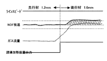
図3は、本発明の効果を示すグラフであり、図2に示した場合と同様に、板厚が1.2mm の先行材から1.6mm の後行材に鋼板が変化する時の無酸化炉2の状態を示したグラフである。図に示しているように条件変更点において応答性の早い設備(本ケースでは誘導加熱装置)を動作させることにより板温を急速に後行材の設定温度まで昇温する事が可能となる。 FIG. 3 is a graph showing the effect of the present invention. Similar to the case shown in FIG. 2, the non-oxidizing furnace 2 when the steel plate changes from a preceding material having a thickness of 1.2 mm to a succeeding material having a thickness of 1.6 mm. It is the graph which showed the state of. As shown in the figure, it is possible to rapidly raise the plate temperature to the set temperature of the succeeding material by operating a facility (induction heating device in this case) that has quick response at the condition change point.
図4に示したようなメッキセクションを持ち、前段部より無酸化炉2と還元炉3と冷却炉4とを直列に配置したガス加熱式の連続焼鈍炉5において、加熱処理の部分に応答性の早い設備として6、7に示すような位置に誘導加熱装置を設置する事を想定する。
In the gas heating type continuous annealing
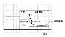
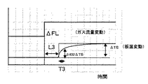
無酸化炉3における従来までの板温制御は無酸化炉3に投入するガス流量を変化させて鋼板温度を調整してきた。しかし、ガス流量の変化応答性と鋼板への熱量の収支バランス、鋼板温度検出装置の設置場所などの制約により、板厚変動に対する鋼板温度の応答は図5のようなむだ時間L1、立ち上がり時間T1のような応答となる。同様にガス流量変更に対する鋼板温度の応答、速度変更に対する鋼板温度の応答、誘導加熱装置出力変更に対する鋼板温度の応答をそれぞれ図6、図7、図8に示す。
Conventional plate temperature control in the
板厚変動、ガス流量変動、速度変動に対する鋼板温度の応答性はそれぞれ、むだ時間L1、L2、L3、立ち上がり時間T1、T2、T3となり、それぞれ通板速度などにより変動する。 Responsiveness of the steel plate temperature to the plate thickness variation, gas flow rate variation, and speed variation becomes dead times L1, L2, and L3, and rise times T1, T2, and T3, respectively, and varies depending on the sheet feeding speed and the like.
誘導加熱装置出力変更に対する鋼板温度の応答(図8)は、他の変動要因に対する鋼板温度の応答と比較すると非常に特徴的な応答となっている。他の鋼板温度の応答では鋼板温度は一定のむだ時間後徐々に変化していくが、誘導加熱装置出力変更に対する鋼板温度の応答では、むだ時間L4後ステップ的に変化している。 The response of the steel plate temperature to the induction heating device output change (FIG. 8) is a very characteristic response compared to the response of the steel plate temperature to other fluctuation factors. In other steel plate temperature responses, the steel plate temperature gradually changes after a certain dead time, but in the steel plate temperature response to the induction heating device output change, it changes stepwise after the dead time L4.
この応答性は先に述べた、応答性の遅い炉で発生する条件変更部分の目標板温からの外れを低減させる為に使用する応答性の早い設備として非常に適合しているため、以下で記述するの出口板温変化代を誘導加熱装置出力に変換して変化させることにより、従来の鋼板温度外れ部分の補償ができることがわかる。 This responsiveness is very suitable as a fast responsive equipment used to reduce the deviation from the target plate temperature of the condition change part generated in the slow responsive furnace described above. It can be seen that by changing the described outlet plate temperature change allowance to the induction heating device output and changing it, it is possible to compensate for the conventional temperature difference portion of the steel plate.
まず、条件変更前のT/ H・Qo ・Qi がそれぞれ条件変更後にT/ H' ・Qo'・Qi'とすると、条件変更時などの熱収支を以下の式(1)より推定できる。
T/H・(Qo −Qi) = T/H' ・(Qo'−Qi')
T/H : ストリップ密度×板厚×板幅×速度 [kg/hr]
Qo : 無酸化炉出口板温での熱容量 [kcal/kg]
Qi : 無酸化炉入口板温(IH手前:常温)での熱容量 [kcal/kg]
First, assuming that T / H, Qo, and Qi before the condition change are T / H ', Qo', and Qi 'after the condition change, the heat balance at the time of the condition change can be estimated from the following equation (1).
T / H. (Qo-Qi) = T / H '. (Qo'-Qi')
T / H: Strip density x board thickness x board width x speed [kg / hr]
Qo: Heat capacity at non-oxidizing furnace outlet plate temperature [kcal / kg]
Qi: Heat capacity at non-oxidation furnace inlet plate temperature (before IH: normal temperature) [kcal / kg]
また、熱容量Qを比熱Cpで置き換えると、次式(2)となる。
T/H・(Cpo・Tro − Cpi・Ti)=T/H' ・(Cpo'・To'−Cpi'・Ti')‥‥(1)
Tro : 無酸化炉出側目標板温 [℃]
To : 無酸化炉出口板温実績 [℃]
Ti : 無酸化炉入口板温(IH手前:常温) [℃]
Cpo : 無酸化炉出口板温での比熱 [kcal/kg ・ ℃]
Cpi : 無酸化炉入口板温(IH手前:常温)での比熱 [kcal/kg ・ ℃]
Cp (T)= A3+2・A4・T+3・A5・T2 +4・A6・T3 ‥‥(2)
Further, when the heat capacity Q is replaced with the specific heat Cp, the following equation (2) is obtained.
T / H · (Cpo · Tro-Cpi · Ti) = T / H '· (Cpo' · To '-Cpi' · Ti ') (1)
Tro: Non-oxidizing furnace delivery target temperature [° C]
To: Non-oxidizing furnace outlet plate temperature [° C]
Ti: Non-oxidizing furnace inlet plate temperature (before IH: normal temperature) [° C]
Cpo: Specific heat at non-oxidizing furnace outlet plate temperature [kcal / kg · ° C]
Cpi: Specific heat at non-oxidation furnace inlet plate temperature (before IH: normal temperature) [kcal / kg · ° C]
Cp (T) = A3 + 2 · A4 · T + 3 · A5 · T 2 +4 · A6 ·
鋼板条件変更による無酸化炉出口の出側板温変動は非常に少ない。
ΔCpo =Cpo −Cpo' ≪ Cpo
であるから、Cpo'=Cpo とし、無酸化炉入口の板温は誘導加熱装置を使用しない場合を想定すると鋼板の状態は一定の前提なので、Cpi =Cpi'、Ti =Ti'とした上で上記(2)式を変換すると加熱条件変更後の無酸化炉出側予測板温を算出できる。
T/H' ・Cpo ・To'=T/ H・(Cpo・Tro − Cpi・Ti)+T/H' ・Cpi'・Ti'
To'={T/ H・(Cpo ・Tro −Cpi ・Ti )+T/H' ・Cpi'・Ti'}/(Cpo ・T/ H' ) ‥‥(3)
また、条件変更後の目標板温変更分を計算すると
ΔTro = Tro'−Tro
これらを加味して無酸化炉出側板温変動量を以下のように算出する。
ΔTo = To'−Tro −ΔTro
There is very little fluctuation in the outlet side plate temperature at the outlet of the non-oxidizing furnace due to the change in steel plate conditions.
ΔCpo = Cpo−Cpo ′ << Cpo
Therefore, assuming that Cpo ′ = Cpo and the plate temperature at the inlet of the non-oxidizing furnace is assumed not to use an induction heating device, the state of the steel plate is assumed to be constant, so that Cpi = Cpi ′ and Ti = Ti ′. When the above equation (2) is converted, the non-oxidation furnace outlet side predicted plate temperature after the heating condition change can be calculated.
T / H ', Cpo, To' = T / H, (Cpo, Tro-Cpi, Ti) + T / H ', Cpi', Ti '
To '= {T / H. (Cpo.Tro-Cpi.Ti) + T / H'.Cpi'.Ti'} / (Cpo.T / H ') (3)
Also, when calculating the target plate temperature change after the condition change, ΔTro = Tro′−Tro
Taking these into consideration, the non-oxidation furnace outlet side plate temperature fluctuation amount is calculated as follows.
ΔTo = To'-Tro-ΔTro
無酸化炉出側板温の変動量を入側誘導加熱装置出力に変換するために無酸化炉入口で投入した熱量が炉内で吸収され、出口で鋼板板温として残存している比率(昇温率)を通板速度、サイズなどの操業条件より導出する。例えば以下の例の場合は一定時間内の鋼板処理量(T/H)から以下の式(4)に従い昇温率を算出する。この昇温率と無酸化炉出側板温の変動量から式(5)に従い誘導加熱装置昇温代ΔTiを求める。
α = a×T/ H+b ‥‥(4)
ΔTi = ΔTo /α ‥‥(5)
T/H : 通板速度(m/hr)×鋼板断面積(m^2)×鋼板比重(t/m^3)
a : 定数 (通板鋼種毎)
b : 定数 (通板鋼種毎)
The amount of heat input at the non-oxidation furnace inlet to convert the fluctuation amount of the non-oxidation furnace outlet side plate temperature into the input induction heating device output is absorbed in the furnace and remains as the steel plate temperature at the outlet (temperature rise Rate) is derived from operating conditions such as plate speed and size. For example, in the case of the following example, the rate of temperature increase is calculated according to the following formula (4) from the steel sheet throughput (T / H) within a certain time. The induction heating device temperature increase allowance ΔTi is obtained from the temperature increase rate and the fluctuation amount of the non-oxidizing furnace outlet side plate temperature according to the equation (5).
α = a × T / H + b (4)
ΔTi = ΔTo / α (5)
T / H: Plate speed (m / hr) x Steel plate cross-sectional area (m ^ 2) x Steel plate specific gravity (t / m ^ 3)
a: Constant (for each sheet steel type)
b: Constant (for each sheet steel type)
つまり、誘導加熱装置にてΔTi(℃)分、鋼板を加熱することにより、無酸化炉出側板温として発生する鋼板温度変動量を補償することを実現させる。このための誘導加熱装置の電力出力ΔIH(kw)の計算はさらに誘導加熱出力に対する有効投入熱量の比率(誘導加熱効率)を板厚、板幅、通板速度、ΔTi、誘導加熱計算出力から導出した上で、以下の式(6)、(7)に従い算出する。
Ptotal = +Gih・[ T/H ・{Q(TIHo)−Q(TIHi)}]
= +Gih・[ T/H ・{Cp(TIHi)・(TIHo−TIHi)}] ‥‥(6)
ΔIH = Ptotal /B×1000/860 ‥‥(7)
Ptotal : 誘導加熱装置必要投入熱量(kcal/hr )
Gih : IH計算ゲイン(ΔIH≧0、ΔIH<0 別に定数を2つもつ) TIHi : 誘導加熱装置入口板温
TIHo : 誘導加熱装置出口板温
B : IH効率(板厚、板幅、通板速度、ΔTi、Ptotal から導出され る)<1.0
In other words, the steel plate is heated by ΔTi (° C.) by the induction heating device, thereby realizing the compensation of the steel plate temperature fluctuation amount generated as the non-oxidizing furnace outlet side plate temperature. For this purpose, the calculation of the power output ΔIH (kw) of the induction heating device further derives the ratio of the effective input heat amount to the induction heating output (induction heating efficiency) from the plate thickness, plate width, plate passing speed, ΔTi, and induction heating calculation output. After that, calculation is performed according to the following formulas (6) and (7).
Ptotal = + Gih [[T / H. {Q (TIHo) -Q (TIHi)}]
= + Gih ・ [T / H ・ {Cp (TIHi) ・ (TIHo−TIHi)}] (6)
ΔIH = Ptotal / B × 1000/860 (7)
Ptotal: Induction heating device required input heat (kcal / hr)
Gih: IH calculation gain (ΔIH ≧ 0, ΔIH <0, with two other constants) TIHi: Induction heating device inlet plate temperature
TIHo: Induction heating device outlet plate temperature
B: IH efficiency (derived from plate thickness, plate width, plate speed, ΔTi, Ptotal) <1.0
ガス加熱炉の従来と同様に熱負荷に変動があった場合、ガス流量の変更を行う。ガス流量変更に伴う板温への影響を考察すると、上記で求めた誘導加熱炉の鋼板温度へ熱量補償量を一定量出力続けると、図9にあるように、ガス加熱炉の鋼板温度に対する効果が十分に現れた時点で逆に外乱となってしまうこととなる。従って、誘導加熱炉出力を応答性の遅い制御端の応答時間に合わせて増減させる必要がある。 When the heat load fluctuates as in the conventional gas heating furnace, the gas flow rate is changed. Considering the influence on the plate temperature due to the gas flow rate change, if a constant amount of heat quantity compensation is continuously output to the steel plate temperature of the induction heating furnace obtained above, the effect on the steel plate temperature of the gas heating furnace as shown in FIG. On the other hand, when it appears sufficiently, it will be a disturbance. Therefore, it is necessary to increase / decrease the induction furnace output in accordance with the response time of the control end having a slow response.
図5、図6、図7にあるように板厚変動、ガス流量変動、速度変動に対する鋼板温度の応答性はそれぞれ、むだ時間L1、L2、L3、立ち上がり時間T1、T2、T3となり、それぞれ通板速度などにより変動する。この応答性の遅い制御端の応答時間及び既存制御出力に合わせて応答性の早い設備の出力の変動させる制御出力を決定することはもちろんである。 As shown in FIGS. 5, 6, and 7, the responsiveness of the steel sheet temperature to the plate thickness variation, gas flow rate variation, and speed variation is the dead time L1, L2, L3 and the rise time T1, T2, T3, respectively. It varies depending on the plate speed. It goes without saying that the control output for changing the output of the equipment with fast response is determined in accordance with the response time of the control end with slow response and the existing control output.
発明の説明は図4に示したような無酸化炉入側6に位置するような応答性の早い設備の出力変化方法に関して記述してきたが、還元炉入側7に位置するような応答性の早い設備の出力変化方法に関しても、ほぼ同様の構成で加熱条件変更部分での鋼板温度の板温外れという課題についても克服できる。 The description of the invention has been described with respect to the method of changing the output of the equipment having a quick response such as that shown in FIG. With regard to the method of quickly changing the output of the equipment, it is possible to overcome the problem that the temperature of the steel sheet is out of the heating condition changing portion with a substantially similar configuration.
図4に示したような、前段部より無酸化炉2と還元炉3と冷却炉4とを直列に配置したガス加熱式の連続焼鈍炉5において、7に示すような加熱処理の部分に応答性の早い設備(誘導加熱装置)を設置している場合、加熱条件が変更になった時の還元炉応答性の遅さを、前述してきたような手順で補償することができるが、一方で無酸化炉の出側板温計直後に位置しているという利点を生かし、無酸化炉出側板温計通過時に基準から外れていた温度代を直後の誘導加熱で補償するという板温制御の考え方を導入する。
In the gas heating type
無酸化炉出側板温外れ分を還元炉前の誘導加熱装置7において吸収するよう制御を行う。
ΔTnof = TSr_nof − TSa_nof
ΔPnof_FB = {Cp(TSa_nof)×ΔTnof ×T/H}・GIH_RTF
ΔIHnof_FB = ΔPnof_FB /B×1000/860
ΔTnof : 無酸化炉出側板温外れ温度 [℃]
TSr_nof : 無酸化炉出側目標板温 [℃]
TSa_nof : 無酸化炉出側実績板温 [℃]
ΔPnof_FB : 無酸化炉出側板温外れ温度のIH必要熱量 [kcal/hr]
Cp(TSa_nof):無酸化炉出側実績板温での比熱 [kcal/kg ・ ℃]
T/H : 無酸化炉出側板温箇所でのT/H(現在) [kg/hr]
B : RTF入側IH効率 [−]
(板厚、板幅、通板速度、ΔTi、Ptotal から導出される)
GIH_RTF : ♯2_IH計算ゲイン(ΔIH≧0、ΔIH<0別に2つもつ) [−]
ΔIHnof_FB : ♯2_IH計算電力変更量(加算分) [kW]
Control is performed so that the
ΔTnof = TSr_nof−TSa_nof
ΔPnof_FB = {Cp (TSa_nof) × ΔTnof × T / H} · GIH_RTF
ΔIHnof_FB = ΔPnof_FB / B × 1000/860
ΔTnof: Non-oxidizing furnace outlet side temperature out-of-temperature [℃]
TSr_nof: Non-oxidizing furnace delivery target temperature [° C]
TSa_nof: Actual temperature at non-oxidizing furnace delivery [° C]
ΔPnof_FB: IH required heat amount of non-oxidation furnace outlet side plate temperature [kcal / hr]
Cp (TSa_nof): Specific heat at the temperature of the non-oxidizing furnace outlet side [kcal / kg · ° C]
T / H: T / H (current) [kg / hr] at the non-oxidizing furnace outlet temperature
B: RTF inlet side IH efficiency [-]
(Derived from plate thickness, plate width, plate speed, ΔTi, Ptotal)
GIH_RTF: # 2_IH calculation gain (ΔIH ≧ 0, ΔIH <0, with two separately) [−]
ΔIHnof_FB: # 2_IH calculation power change amount (addition) [kW]
還元炉前の誘導加熱装置7を無酸化炉の板温外れ補正に使用する場合、昇温/降温両パターンに対応する必要がある。つまり、昇温の場合は誘導加熱炉出力アップ、降温の場合は誘導加熱炉出力ダウンさせるだけの出力変動分以上の誘導加熱出力させておき、上記の補償分との加算を以下のように行う。
ΔIH2total(t+1)= ΔIHa(t)+ΔIHbace+ΔIHrtf_step+
ΔIHnof_FB
ΔIH2total(t+1) :♯2_IH計算電力変更量 [kW]
ΔIHa :♯2_IH計算電力実績値 [kW]
ΔIHbace :定常出力値変更に対する♯2_IH計算電力変更量 [kW]
ΔIHrtf_step : RTF入口通過コイル変化によるステップ変更に対する♯2
_IH計算電力変更量 [kW]
ΔIHnof_FB : NOF出口通過コイル板温はずれ補償用♯2_IH計算電力変
更量 [kW]
When the
ΔIH2total (t + 1) = ΔIHa (t) + ΔIHbace + ΔIHrtf_step +
ΔIHnof_FB
ΔIH2total (t + 1): # 2_IH calculation power change amount [kW]
ΔIHa: # 2_IH calculated power actual value [kW]
ΔIHbace: # 2_IH calculation power change amount [kW] with respect to steady output value change
ΔIHrtf_step: # 2 for step change due to RTF inlet passage coil change
_IH calculation power change [kW]
ΔIHnof_FB: NOF outlet passage coil plate temperature deviation compensation # 2_IH calculated power variation
Renewal [kW]
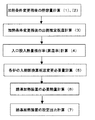
既存の応答性の遅い炉で発生する条件変更部分の目標板温からの外れを低減させる為に応答性の早い設備の出力を適切に調整する計算式(1)から(7)の流れを図10に示す。 Figure 7 shows the flow of calculation formulas (1) to (7) for appropriately adjusting the output of the fast-responsive equipment in order to reduce the deviation from the target plate temperature of the condition change part that occurs in the existing slow-responsive furnace. 10 shows.
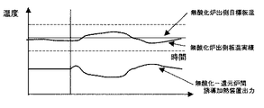
無酸化炉出側板温外れ分を還元炉前の誘導加熱装置7において吸収するよう誘導加熱装置の出力を制御した場合の無酸化炉出側板温と無酸化炉−還元炉間誘導加熱出力及び還元炉ガス流量制御の関係を図11に示す。
Non-oxidation furnace outlet side plate temperature, non-oxidation furnace-reduction furnace induction heating output, and reduction when the output of the induction heating apparatus is controlled so that the
1 めっき装置
2 無酸化炉
3 還元炉
4 冷却炉
5 ガス加熱式の連速焼鈍炉
6 誘導加熱装置
7 誘導加熱装置
DESCRIPTION OF SYMBOLS 1 Plating apparatus 2
Claims (3)
In the continuous annealing method for steel plates in a gas-heating type continuous annealing furnace, in order to reduce the quality influence margin of the deviation from the target plate temperature that could not be suppressed by the furnace in the front, the responsiveness behind the temperature measurement part In parallel with the calculation of the input heat quantity of the equipment with the fastest time, when the heating conditions are changed, the residual rate of heat input to the inlet (rising rate) derived from the operating conditions such as the predicted equipment outlet side plate temperature, plate passing speed, and steel plate size are estimated. In order to reduce the quality influence cost and the value calculated as the amount of heat necessary to change the heating conditions, converted into the steel plate temperature change amount required for heating in equipment with quick response at the equipment inlet. A method for controlling the temperature of a continuously annealed steel sheet, characterized by adding and setting the input heat amount of the fast-responsive equipment calculated in the above.
Priority Applications (1)
| Application Number | Priority Date | Filing Date | Title |
|---|---|---|---|
| JP2004119888A JP2005298941A (en) | 2004-04-15 | 2004-04-15 | Continuous annealing temperature control method for steel sheet |
Applications Claiming Priority (1)
| Application Number | Priority Date | Filing Date | Title |
|---|---|---|---|
| JP2004119888A JP2005298941A (en) | 2004-04-15 | 2004-04-15 | Continuous annealing temperature control method for steel sheet |
Publications (1)
| Publication Number | Publication Date |
|---|---|
| JP2005298941A true JP2005298941A (en) | 2005-10-27 |
Family
ID=35330847
Family Applications (1)
| Application Number | Title | Priority Date | Filing Date |
|---|---|---|---|
| JP2004119888A Pending JP2005298941A (en) | 2004-04-15 | 2004-04-15 | Continuous annealing temperature control method for steel sheet |
Country Status (1)
| Country | Link |
|---|---|
| JP (1) | JP2005298941A (en) |
Cited By (7)
| Publication number | Priority date | Publication date | Assignee | Title |
|---|---|---|---|---|
| JP2009263701A (en) * | 2008-04-23 | 2009-11-12 | Nippon Steel Corp | Method for heating material to be heated |
| JP2015030891A (en) * | 2013-08-05 | 2015-02-16 | Jfeスチール株式会社 | Method and apparatus for control of continuous annealing line |
| CN104962727A (en) * | 2015-07-29 | 2015-10-07 | 上海宝钢节能环保技术有限公司 | Continuous annealing furnace heating section furnace-temperature control system and method |
| JP2018123364A (en) * | 2017-01-31 | 2018-08-09 | Jfeスチール株式会社 | Steel plate temperature control method and steel plate temperature control device |
| PL424288A1 (en) * | 2018-01-16 | 2019-07-29 | Górzny Wojciech Hydropress | Protective sealing plug for clenching pressure pipes and systems end pieces |
| CN119877107A (en) * | 2025-03-27 | 2025-04-25 | 青岛华芯晶电科技有限公司 | Sapphire annealing furnace running state monitoring control method |
| EP4527952A4 (en) * | 2022-07-04 | 2025-11-26 | Jfe Steel Corp | METHOD FOR ANNEALING HOT-ROLLED STEEL STRIP AND METHOD FOR PRODUCING ELECTROMAGNETIC STEEL SHEET USING THIS ANNEALING METHOD |
-
2004
- 2004-04-15 JP JP2004119888A patent/JP2005298941A/en active Pending
Cited By (7)
| Publication number | Priority date | Publication date | Assignee | Title |
|---|---|---|---|---|
| JP2009263701A (en) * | 2008-04-23 | 2009-11-12 | Nippon Steel Corp | Method for heating material to be heated |
| JP2015030891A (en) * | 2013-08-05 | 2015-02-16 | Jfeスチール株式会社 | Method and apparatus for control of continuous annealing line |
| CN104962727A (en) * | 2015-07-29 | 2015-10-07 | 上海宝钢节能环保技术有限公司 | Continuous annealing furnace heating section furnace-temperature control system and method |
| JP2018123364A (en) * | 2017-01-31 | 2018-08-09 | Jfeスチール株式会社 | Steel plate temperature control method and steel plate temperature control device |
| PL424288A1 (en) * | 2018-01-16 | 2019-07-29 | Górzny Wojciech Hydropress | Protective sealing plug for clenching pressure pipes and systems end pieces |
| EP4527952A4 (en) * | 2022-07-04 | 2025-11-26 | Jfe Steel Corp | METHOD FOR ANNEALING HOT-ROLLED STEEL STRIP AND METHOD FOR PRODUCING ELECTROMAGNETIC STEEL SHEET USING THIS ANNEALING METHOD |
| CN119877107A (en) * | 2025-03-27 | 2025-04-25 | 青岛华芯晶电科技有限公司 | Sapphire annealing furnace running state monitoring control method |
Similar Documents
| Publication | Publication Date | Title |
|---|---|---|
| CN103397171B (en) | Method for determining furnace-temperature set value of billet heating furnace | |
| CN107801403B (en) | Fast Response Heaters and Associated Control Systems for Use with Metal Processing Furnaces | |
| CN102455135A (en) | Open fire heating furnace temperature control method and control equipment | |
| SK31799A3 (en) | Induction heaters to improve transitions in continuous heating systems, and method | |
| JP5604812B2 (en) | Reflow furnace and control method thereof | |
| JP2005298941A (en) | Continuous annealing temperature control method for steel sheet | |
| US8893402B2 (en) | Method for controlling a protective gas atmosphere in a protective gas chamber for the treatment of a metal strip | |
| CN114756065B (en) | Plate temperature control method for hot dip galvanized strip steel before entering zinc pot | |
| JPS6056406B2 (en) | Continuous annealing furnace with induction heating section | |
| JP4975235B2 (en) | Material temperature control system in continuous strip material processing line | |
| US20210032720A1 (en) | Method of heating steel sheet in continuous annealing and continuous annealing facility | |
| CN114054704A (en) | Method for controlling temperature of tundish molten steel in heavy rail steel smelting process | |
| CN116536506A (en) | Furnace pressure control method of atmosphere annealing furnace | |
| JP2005248208A (en) | Plate temperature control method in induction heating of galvannealed steel sheet. | |
| JP2019520542A (en) | How to preheat the fluid upstream of the furnace | |
| JP5742311B2 (en) | Method and apparatus for preventing warpage of rolled material in hot rolling line | |
| JP7052671B2 (en) | Metal band temperature control method and temperature control device | |
| JP2003033808A (en) | Hot rolling method and apparatus | |
| JP2596229B2 (en) | Manufacturing method of galvannealed steel sheet | |
| JP4064253B2 (en) | Steel strip continuous heat treatment equipment and combustion method thereof | |
| KR101169125B1 (en) | Material temperature control system in continuous strip material treatment line | |
| JPH0754055A (en) | Steel strip temperature control method in continuous annealing furnace | |
| JP2007217754A (en) | Method and apparatus for controlling bath temperature of molten zinc pot | |
| CN115341079A (en) | A method for controlling the backflow of furnace gas in a continuous normalizing furnace | |
| JP2005120409A (en) | Manufacturing method of high-strength steel sheet with excellent material uniformity in the longitudinal direction of the steel sheet |
Legal Events
| Date | Code | Title | Description |
|---|---|---|---|
| A621 | Written request for application examination |
Free format text: JAPANESE INTERMEDIATE CODE: A621 Effective date: 20060905 |
|
| A131 | Notification of reasons for refusal |
Free format text: JAPANESE INTERMEDIATE CODE: A131 Effective date: 20091002 |
|
| A521 | Written amendment |
Free format text: JAPANESE INTERMEDIATE CODE: A523 Effective date: 20091130 |
|
| A02 | Decision of refusal |
Free format text: JAPANESE INTERMEDIATE CODE: A02 Effective date: 20100205 |