JP2005298940A - Method for fitting electric corrosion-preventive electrode to concrete and fixing tool for electric corrosion-preventive electrode - Google Patents
Method for fitting electric corrosion-preventive electrode to concrete and fixing tool for electric corrosion-preventive electrode Download PDFInfo
- Publication number
- JP2005298940A JP2005298940A JP2004119837A JP2004119837A JP2005298940A JP 2005298940 A JP2005298940 A JP 2005298940A JP 2004119837 A JP2004119837 A JP 2004119837A JP 2004119837 A JP2004119837 A JP 2004119837A JP 2005298940 A JP2005298940 A JP 2005298940A
- Authority
- JP
- Japan
- Prior art keywords
- electrode
- concrete
- fixing
- anticorrosion
- corrosion
- Prior art date
- Legal status (The legal status is an assumption and is not a legal conclusion. Google has not performed a legal analysis and makes no representation as to the accuracy of the status listed.)
- Granted
Links
- 238000000034 method Methods 0.000 title claims abstract description 26
- 238000005260 corrosion Methods 0.000 claims abstract description 30
- 239000004570 mortar (masonry) Substances 0.000 claims description 12
- 238000003825 pressing Methods 0.000 claims description 6
- 238000003860 storage Methods 0.000 claims description 6
- 230000007797 corrosion Effects 0.000 abstract description 14
- 230000003449 preventive effect Effects 0.000 abstract 2
- 230000003014 reinforcing effect Effects 0.000 description 14
- 238000009826 distribution Methods 0.000 description 11
- 229910052751 metal Inorganic materials 0.000 description 11
- 239000002184 metal Substances 0.000 description 11
- 238000010586 diagram Methods 0.000 description 7
- 229920003002 synthetic resin Polymers 0.000 description 7
- 239000000057 synthetic resin Substances 0.000 description 7
- 229910000831 Steel Inorganic materials 0.000 description 6
- 239000000463 material Substances 0.000 description 6
- 239000010959 steel Substances 0.000 description 6
- RTAQQCXQSZGOHL-UHFFFAOYSA-N Titanium Chemical compound [Ti] RTAQQCXQSZGOHL-UHFFFAOYSA-N 0.000 description 4
- 230000008602 contraction Effects 0.000 description 4
- 239000011810 insulating material Substances 0.000 description 4
- 239000010936 titanium Substances 0.000 description 4
- 229910052719 titanium Inorganic materials 0.000 description 4
- 239000004677 Nylon Substances 0.000 description 3
- 239000004743 Polypropylene Substances 0.000 description 3
- 230000000694 effects Effects 0.000 description 3
- 150000004820 halides Chemical class 0.000 description 3
- 229920001778 nylon Polymers 0.000 description 3
- -1 polypropylene Polymers 0.000 description 3
- 229920001155 polypropylene Polymers 0.000 description 3
- 230000015572 biosynthetic process Effects 0.000 description 2
- 239000003054 catalyst Substances 0.000 description 2
- 238000007796 conventional method Methods 0.000 description 2
- XLYOFNOQVPJJNP-UHFFFAOYSA-N water Substances O XLYOFNOQVPJJNP-UHFFFAOYSA-N 0.000 description 2
- UXVMQQNJUSDDNG-UHFFFAOYSA-L Calcium chloride Chemical compound [Cl-].[Cl-].[Ca+2] UXVMQQNJUSDDNG-UHFFFAOYSA-L 0.000 description 1
- 229910001628 calcium chloride Inorganic materials 0.000 description 1
- 239000001110 calcium chloride Substances 0.000 description 1
- 238000004210 cathodic protection Methods 0.000 description 1
- 239000011248 coating agent Substances 0.000 description 1
- 238000000576 coating method Methods 0.000 description 1
- 239000012141 concentrate Substances 0.000 description 1
- 238000010276 construction Methods 0.000 description 1
- 238000005536 corrosion prevention Methods 0.000 description 1
- 238000005336 cracking Methods 0.000 description 1
- 230000005611 electricity Effects 0.000 description 1
- 239000010411 electrocatalyst Substances 0.000 description 1
- 230000008014 freezing Effects 0.000 description 1
- 238000007710 freezing Methods 0.000 description 1
- 235000014413 iron hydroxide Nutrition 0.000 description 1
- NCNCGGDMXMBVIA-UHFFFAOYSA-L iron(ii) hydroxide Chemical compound [OH-].[OH-].[Fe+2] NCNCGGDMXMBVIA-UHFFFAOYSA-L 0.000 description 1
- 231100000989 no adverse effect Toxicity 0.000 description 1
- BASFCYQUMIYNBI-UHFFFAOYSA-N platinum Chemical group [Pt] BASFCYQUMIYNBI-UHFFFAOYSA-N 0.000 description 1
- 230000010287 polarization Effects 0.000 description 1
- 150000003839 salts Chemical class 0.000 description 1
- 239000013535 sea water Substances 0.000 description 1
- 239000000126 substance Substances 0.000 description 1
Images



Landscapes
- Prevention Of Electric Corrosion (AREA)
Abstract
Description
本発明は、コンクリート構造物中の鉄筋等の鋼材の電気防食に関し、特にコンクリート面への電気防食電極の固定方法およびそれに使用する電気防食電極の固定治具に関する。 The present invention relates to an anticorrosion of a steel material such as a reinforcing bar in a concrete structure, and more particularly to a method of fixing an anticorrosion electrode to a concrete surface and a fixing jig for an anticorrosion electrode used therefor.
コンクリート構造物中の鉄筋は、コンクリート中のアルカリ性環境においては通常は鉄筋の腐食は進行しない。しかし、沿岸部に位置するコンクリート構造物や凍結防止用に散布された塩化カルシウム、食塩等のハロゲン化物を含有した水に接触する構造物においては、ハロゲン化物がコンクリート中に浸入して、鉄筋の腐食が生じることがある。 Reinforcing bars in concrete structures usually do not proceed with corrosion in an alkaline environment in concrete. However, in concrete structures located in coastal areas and structures that come into contact with water containing halides such as calcium chloride and salt sprayed to prevent freezing, halides penetrate into the concrete and Corrosion may occur.
鉄筋が腐食すると、生成した鉄の水酸化物等によって体積が膨脹して、周囲のコンクリートに応力が作用してコンクリートのひび割れが生じる。コンクリートに生じたひび割れによって、さらに海水等のハロゲン化物を含有した水が浸入すると、さらに鉄筋の腐食が進行し、コンクリート構造物の一部の落下等の重大な問題が生じる可能性がある。 When the reinforcing bars corrode, the volume is expanded by the generated iron hydroxide and the like, and stress is applied to the surrounding concrete to cause cracking of the concrete. If water containing halides such as seawater enters due to cracks generated in the concrete, corrosion of the reinforcing bars further proceeds, and serious problems such as dropping of a part of the concrete structure may occur.
コンクリート構造物中の鉄筋等の鋼構造物の腐食を防止する手段として、コンクリート構造物の表面に、チタン等の耐食性金属の表面に電極触媒被覆を形成した電気防食電極を装着し、電気防食電極を陽極、鉄筋を陰極として鉄筋に防食電流を供給する電気防食方法が知られており、電流の印加によって、腐食環境下にある鉄筋の電位を、腐食が生じない卑の方向へと変化させて腐食が生じないものとするものである。 As a means of preventing corrosion of steel structures such as reinforcing bars in concrete structures, an anticorrosion electrode with an electrode catalyst coating formed on the surface of a corrosion-resistant metal such as titanium is attached to the surface of the concrete structure. There is a known anti-corrosion method that supplies anti-corrosion current to the reinforcing bar with the reinforcing bar as the anode and the reinforcing bar as the cathode. By applying the current, the potential of the reinforcing bar in the corrosive environment is changed to the base direction where corrosion does not occur. It is assumed that corrosion does not occur.
電気防食電極のコンクリート面への設置方法には各種の方法が知られている。
一般には、コンクリート表面に防食電極を取り付ける際には、電気防食電極および各電気防食電極への電流分配部材を所望の間隔でコンクリート構造物に配置した後に、防食電極および電流分配部材の取り付け位置を定めて所定の深さおよび径の孔を振動ドリル等によって形成した後に金属製の取り付け具によって固定することが行われている。
Various methods are known for installing the anticorrosion electrode on the concrete surface.
In general, when the anticorrosion electrode is attached to the concrete surface, the position of the anticorrosion electrode and the current distribution member is set after arranging the electric anticorrosion electrode and the current distribution member to each of the anticorrosion electrodes on the concrete structure at a desired interval. A predetermined hole having a predetermined depth and diameter is formed by a vibration drill or the like and then fixed by a metal fitting.
ところが、電気防食電極あるは電流分配部材をコンクリート表面に固定する際に、金属製の固定治具を用いた場合には、電気抵抗の小さい金属固定治具に防食電流が集中し、コンクリート中の鋼材へ均一に防食電流が供給されないという問題が生じる。また、金属固定治具とコンクリート内部の鉄筋等の鋼材が接触したまま施工されると電気防食電極と防食対象の鋼材の間が電気的に短絡し、電気防食の効果を発揮できないという間題点があった。
さらに、固定治具として使用する材料は、電位的には電気防食電極と同等の電位とされるので、使用する材料によっては固定治具が変質して膨張等を起こし、コンクリートのひび割れを生じさせる可能性もあった。
However, when a metal fixing jig is used when fixing the anticorrosion electrode or the current distribution member to the concrete surface, the anticorrosion current concentrates on the metal fixing jig with a small electric resistance, and the There arises a problem that the anticorrosion current is not uniformly supplied to the steel material. In addition, if it is constructed with the metal fixture and steel such as rebar inside the concrete in contact, the electrical protection electrode and the steel to be protected are electrically short-circuited, and the effect of electrical protection cannot be exhibited. was there.
Furthermore, since the material used as the fixing jig is the same potential as that of the anti-corrosion electrode, the fixing jig may change in quality depending on the material used, causing expansion and the like, causing concrete cracks. There was also a possibility.
コンクリート構造物の表面への防食電極の取り付け手段としては、「例示した電極の取り付け構造ではいずれも取り付け具として絶縁性取付ボルトを例に挙げたけれども、この取付具は、不溶性電極をコンクリート構造物に圧接固定できる部材ならばどのような部材でもよいことは勿論であり、例えば耐食性金属ボルトや、棒状、あるいはピン状のホールインアンカー、さらにはひも状あるいは帯状の締め付け具を用いてもよい。」(特許文献1)と記載のように、電気防食電極の固定治具には格別の注意が払われることはなかった。 As a means for attaching the anticorrosion electrode to the surface of the concrete structure, “In the exemplified electrode mounting structure, an insulating mounting bolt is taken as an example of the mounting structure. Of course, any member can be used as long as it is capable of being pressed and fixed to, for example, a corrosion-resistant metal bolt, a rod-like or pin-like hole-in anchor, and a string-like or belt-like fastener. As described in (Patent Document 1), no particular attention was paid to the fixing jig for the anticorrosion electrode.
しかしながら、電気防食電極の固定に使用する固定治具は電気防食電極との当接面が充分な面積を有するものであることが電気防食電極あるいは電流分配部材を安定に固定するためには好ましいが、チタン等の耐食性金属からなる電流分配部材、あるいはチタン等の耐食性金属の表面に電極触媒物質を形成した電極は、陽分極されることによって安定な特性を示すものであるので、使用環境においては電気の通電において障害となる物質で被覆される面積を最小にすることが必要となる。
ところが、従来の固定治具にあっては、単に電気防食電極を固定する点に着目されていたのみであった。
However, in order to stably fix the electrode protection electrode or the current distribution member, it is preferable that the fixing jig used for fixing the electrode protection electrode has a sufficient contact surface with the electrode protection electrode. In addition, the current distribution member made of a corrosion-resistant metal such as titanium, or the electrode formed with an electrocatalyst material on the surface of the corrosion-resistant metal such as titanium shows stable characteristics by being positively polarized. It is necessary to minimize the area covered with a substance that hinders electricity conduction.
However, in the conventional fixing jig, attention has only been paid to the point of fixing the anticorrosion electrode.
本出願人は、こうした問題点を解決するために、コンクリート構造物に形成した固着用の穴に嵌合する柱状部と電気防食電極面に当接するフランジ部を有しフランジ部には電気防食電極を覆う充填材が通過する開口部を有するとともに、電気絶縁性部材によって形成したコンクリート構造物の電気防食電極の取り付け具を提案している(特許文献2)。
この方法は、コンクリート構造物の表面に対して電気防食電極を確実な取り付けが可能な方法であるが、電気極防食電極の取り付け具の固着には、取り付け具の固着用の穴を形成することが不可欠であった。
In order to solve such problems, the present applicant has a columnar portion that fits into a fixing hole formed in a concrete structure and a flange portion that abuts on the surface of the anticorrosive electrode, and the flange portion has an anticorrosive electrode. In addition, an attachment for an anticorrosion electrode of a concrete structure formed by an electrically insulating member is proposed (Patent Document 2).
In this method, the anticorrosion electrode can be securely attached to the surface of the concrete structure. However, an attachment hole for the attachment of the attachment must be formed in the attachment of the attachment of the electrode protection electrode. Was essential.
図4は、従来の電気防食電極の固定方法を説明する図である。
図4(A)は平面図であり、図4(B)は、図4(A)において、A−A線で切断した断面図である。
図4(A)に示すように、コンクリート1の表面に電気防食電極3が配置されており、コンクリート1に形成した穴14に、電気絶縁性の合成樹脂からなる固定ピン15を嵌合させて、固定ピン15の先端に設けたフランジ部15Aによってコンクリート1の表面に電気防食電極3を固着したものである。電気防食電極3には電流分配部材5が結合されて、各電気防食電極3に対して防食電流が供給される。また、電気防食電極3への配線等を完了した後に、コンクリート表面はモルタル10によって覆われている。
FIG. 4 is a view for explaining a conventional method of fixing an anticorrosion electrode.
4A is a plan view, and FIG. 4B is a cross-sectional view taken along line AA in FIG. 4A.
As shown in FIG. 4A, the
電気防食電極を被覆するためのモルタルは、固定ピンの上部から充填されるので、固定ピンと電気防食電極との会合部17において空洞が生じて電流が均等に流れない部分が生じる可能性があった。
また、図4(C)は、電極ホルダー内に電気防食電極を設置した場合の断面を説明する図である。
電極ホルダー11は、コンクリート1に設けた穴14に合成樹脂製の固定ピン15を嵌合させて固着されており、固定ピン15の頭部に設けたフランジ部15Aの上部に電気防食電極3を載置して、電気絶縁性の合成樹脂からなる結束部材18によって取り付けた後に、電極ホルダー11内にモルタル10を充填したものである。
図4(C)に示す方法では、数多くの固定ピン15が必要となるので、固定ピンによって防食電流が不均一となるおそれがあった。
Since the mortar for covering the anticorrosion electrode is filled from the upper part of the fixing pin, there is a possibility that a cavity is generated at the
FIG. 4C is a view for explaining a cross section when an anticorrosion electrode is installed in the electrode holder.
The
In the method shown in FIG. 4C, a large number of
また、以上のようにいずれの方法の場合にも、コンクリート面に対して多数の穴を設けることが不可欠であった。
コンクリート面への電気防食電極を取り付け個所は様々な場所があり、足場等を設置しても作業性が良くない場所もあり、コンクリート面への固着用の穴の形成が必要がない、あるいは形成すべき穴の個数が少なく、取り付けに要する作業時間をより短縮することが可能な、電気防食電極の固定治具および電気防食電極の固定方法が求められていた。
There are various places where the anticorrosive electrode is attached to the concrete surface, and there are places where workability is not good even if a scaffold is installed, and it is not necessary or necessary to form a hole for fixing to the concrete surface There has been a demand for an anticorrosion electrode fixing jig and a method for fixing an anticorrosion electrode, which can reduce the number of holes to be formed and reduce the work time required for attachment.
本発明は、電気防食電極をコンクリート面の所定の位置に固定することが容易であり、電気防食効果に対して悪影響を及ぼすことがなく、取り付けに要する時間を短縮可能な電気防食電極の固定方法および電気防食電極の固定治具を提供することを課題とするものである。 The present invention provides a method for fixing an anti-corrosion electrode that can easily fix the anti-corrosion electrode at a predetermined position on a concrete surface, has no adverse effect on the anti-corrosion effect, and can reduce the time required for attachment. It is another object of the present invention to provide a fixing jig for an anticorrosion electrode.
本発明の課題は、コンクリートへの電気防食電極の固定方法において、コンクリートに配置した電気防食電極を、コンクリートに面する側と反対面を、コンクリートに設けた電気防食電極の収納部の壁面を支点とし、電気防食電極をコンクリート側に押圧する固定治具によって固定するコンクリートへの電気防食電極の固定方法によって解決することができる。
また、電気防食電極の収納部が、コンクリート面に形成した溝であり、溝の壁面に固定治具の支点部を設けた前記のコンクリートへの電気防食電極の固定方法である。
電気防食電極の収納部が、コンクリート面に設けた電気防食電極を保持し内部にモルタルを充填する電気防食電極ホルダーであり、電気防食電極ホルダーの壁面に固定治具の支点を配置した電気防食電極の固定方法である。
An object of the present invention is to fix an electrocorrosive electrode to concrete in a method for fixing the anticorrosive electrode to concrete, with the surface opposite to the side facing the concrete being the fulcrum of the wall of the storage portion of the electrode provided on the concrete. This can be solved by a method of fixing the anticorrosion electrode to the concrete that is fixed by a fixing jig that presses the anticorrosion electrode to the concrete side.
Further, in the above-described method of fixing the anticorrosive electrode to the concrete, the storage portion of the anticorrosive electrode is a groove formed on the concrete surface, and a fulcrum portion of a fixing jig is provided on the wall surface of the groove.
The anti-corrosion electrode holder is an anti-corrosion electrode holder that holds the anti-corrosion electrode provided on the concrete surface and fills the interior with mortar, and the anti-corrosion electrode has a fixing jig fulcrum disposed on the wall of the anti-corrosion electrode holder This is the fixing method.
電気防食電極をコンクリートに固定する電気防食電極の固定治具において、電気防食電極を押圧する押圧部の中心を通る面に対して対称な2つの支点部を有し、押圧部と2つの支点部は、曲面状もしくは直線状の部材で結合された電気防食電極の固定治具である。
2つの支点を結ぶ線に平行または垂直方向に対して伸縮する前記の電気防食電極の固定治具である。
In a fixing jig for an anticorrosion electrode for fixing the anticorrosion electrode to concrete, the jig has two fulcrum parts symmetrical to a plane passing through the center of the pressing part for pressing the anticorrosion electrode, and the pressing part and the two fulcrum parts Is a fixing jig for an anticorrosion electrode joined by a curved or linear member.
It is a fixing jig for the above-mentioned cathodic protection electrode that expands and contracts in a direction parallel or perpendicular to a line connecting two supporting points.
本発明の電気防食電極の固定方法および固定治具によって、コンクリート構造物の鋼材の防食用の電気防食電極の取り付けが容易となり、しかも電気防食電極の固定部においてコンクリート面との間で空間が生じる可能性を小さくすることができるとともに、電気防食電極と鉄筋との間に存在する絶縁性の固定ピンの本数を減少させることができるので、電気防食電極に安定して通電することができるので、コンクリート構造物への電気防食効果を高めることが可能となる。 With the method and fixture for fixing an anticorrosive electrode according to the present invention, it becomes easy to attach an anticorrosive electrode for corrosion prevention of steel of a concrete structure, and a space is formed between the surface of the anticorrosive electrode and the concrete surface. Since the possibility can be reduced and the number of insulating fixing pins existing between the anticorrosion electrode and the reinforcing bar can be reduced, it is possible to stably energize the anticorrosion electrode, It becomes possible to enhance the anticorrosion effect on the concrete structure.
本発明のコンクリート面への電気防食電極の固定方法は、電気防食電極をコンクリート面へ固定する電極固定治具として、コンクリート面に穴を形成することが不要で装着が容易な電極の固定治具を使用したことによって、施工に要する時間も短縮することを可能とし、また防食電流の値を均一なものとすることが可能であることを見出したものである。 The method for fixing an anticorrosive electrode to a concrete surface according to the present invention is an electrode fixing jig for fixing an anticorrosive electrode to a concrete surface, and it is not necessary to form a hole in the concrete surface and can be easily mounted. It has been found that the time required for the construction can be shortened and the value of the anticorrosion current can be made uniform.
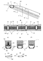
以下に図面を参照して本発明を説明する。
図1は、本発明の電気防食電極の取り付け方法の一実施例を説明する図である。
図1(A)は、電気防食電極の取り付け方法を説明する一部を切り欠いた斜視図であり、図1(B)は、固定治具を説明する斜視図である。
コンクリート1の表面に設けた防食電極の収納部となる溝2が形成されており、溝2には電気防食電極3が配置されている。電気防食電極3は、溝2の壁面を支点として挿入した固定治具4によって溝の底部のコンクリート面に対して密着して固定されている。
電気防食電極3は、チタン等の耐食性の金属上に白金族金属あるいは酸化物を含有する電極触媒層を形成した、帯状、リボン状の電極を用いることができるが、開孔を設けたり、あるいはエキスパンデッドメタルを用いることによって、充填されるモルタルとの接触面積を大きくしたものが好ましい。
The present invention will be described below with reference to the drawings.
FIG. 1 is a diagram for explaining an embodiment of a method for attaching an anticorrosive electrode according to the present invention.
FIG. 1A is a perspective view with a part cut away for explaining a method of attaching an anticorrosion electrode, and FIG. 1B is a perspective view for explaining a fixing jig.
A
As the
固定治具4は、溝の両壁面を支点として電極面に対して反力を発生する弾性部材から形成されているので、溝2に配置した電気防食電極3の上面から固定治具4を装着するのみで、電気防食電極をコンクリート面に対して容易に固定することができる。電気防食電極3には電流分配部材5が結合されて、防食電流供給装置6の正極側7に結線され、また、コンクリート中の鉄筋8は負極側9に結線され、コンクリートの表面にはモルタル10によって覆われている。
Since the fixing
また、図1(B)に示すように、固定治具4は、両側に支点部4Aを有し、中央には、電気防食電極を押圧する作用部4Bを有している。
固定治具4を溝内に挿入すると、溝の両壁面で、両側の支点部4Aが押圧される結果、作用部4Bには下向きの力4Cが作用して電気防食電極を固定することができる。
固定治具4は、板状の弾性を有する部材、あるいは線状の部材によって形成することができる。板状の弾性部材を使用する場合には作用部4Bには開口部を設けても良い。開口部を設けることによって電気防食電極とモルタルとの密着性が良好となり、防食電流の分配性能が向上する。また、固定治具4は電流を通電しない絶縁性の材料であることが好ましく、具体的には、ポリプロピレン、66ナイロン等の単位断面積当たりの強度が大きな合成樹脂製の部材を用いることが好ましい。
As shown in FIG. 1B, the fixing
When the fixing
The fixing
図2は、本発明の他の実施例を説明する図である。
図2(A)は、電極ホルダーを使用した他の例を説明する斜視図であり、図2(B)は、一部の拡大図であり、また図2(C)は固定治具を説明する斜視図である。
図2に示した実施例は、実施例1のようにコンクリート1の表面に、電気防食電極の配置用の溝を設けることに代えて、電極ホルダー11を設けたものである。
電極ホルダー11の内部には、電気防食電極3が配置されており、電気防食電極3は、電極ホルダー11の内部に配置した固定治具4によって、電極ホルダー11内の電気防食電極をコンクリート面に押圧し密着して固定されている。
FIG. 2 is a diagram for explaining another embodiment of the present invention.
FIG. 2A is a perspective view illustrating another example using an electrode holder, FIG. 2B is a partially enlarged view, and FIG. 2C illustrates a fixing jig. FIG.
In the embodiment shown in FIG. 2, an
The
また、電極ホルダー11のコンクリート面との密着面には、電極がコンクリート面と密着するための開口部を有し、電極ホルダーをコンクリート面に密着固定するための固定部(図示しない)が設けられており、固定部では固定ピン(図示しない)によって電極ホルダー11がコンクリート2に固定されている。
また、電気防食電極3には電流分配部材5が結合されて、防食電流供給装置6の正極側7に結線され、また、コンクリート中の鉄筋8は負極側9に結線されている。
In addition, the
In addition, a
また、図2(C)に示すように、固定治具4は、両側に支点部4Aを有し、中央には、電気防食電極を押圧する作用部4Bを有している。
固定治具4を電極ホルダー11内に挿入すると、電極ホルダーの内面で両側の支点部4Aが押圧される結果、作用部4Bには下向きの力4Cが作用して電気防食電極を固定することができる。
As shown in FIG. 2C, the fixing
When the fixing
固定治具4は、板状の弾性を有する部材、あるいは線状の部材によって形成することができる。板状の弾性を有する部材を用いる場合には、電気防食電極と接触する部分に開口部を設けても良い。開口部を設けた場合には、開口部を通じてモルタルが電気防食電極と直接に接触するので電気防食電極とモルタルとの密着性が高まり、防食電流の分配性能が向上する。また、固定治具4は電流を通電しない絶縁性の材料であることが好ましく、具体的には、ポリプロピレン、66ナイロン等の単位断面積当たりの強度が大きな合成樹脂製の部材を用いることが好ましい。
The fixing
この例で示したように電極ホルダー11によって電気防食電極を配置することにより、電気防食電極をモルタルで被覆する際にコンクリート面全体を被覆する必要がないので、電気防食電極の設置による重量増加を小さくすることが可能となる。
また、電極ホルダーとしては、合成樹脂製材料等の耐食性が大きな絶縁性材料を使用することができるが、電極ホルダーを防食対象のコンクリート構造物と同等の導電率を有するモルタルを使用して作製したもので良い。これによって電極ホルダーを通じた電気防食電流の通電が可能となる。
By arranging the anticorrosion electrode by the
In addition, as the electrode holder, an insulating material having a high corrosion resistance such as a synthetic resin material can be used. Good thing. As a result, it is possible to energize the anticorrosion current through the electrode holder.
図3は、本発明の他の実施例を説明する図である。
図3(A)は、電極ホルダーを使用した例を説明する斜視図であり、図3(B)は、図3(A)のA―A’線で切断し、電極ホルダー内のモルタルを除いた状態を説明する図であって電気防食電極をコンクリート面とは反対側からコンクリート面側を見た図である。また、図3(C)、(D)、(E)は、それぞれ図3(A)あるいは(B)において、B−B’線、C−C’線、D―D’線での切断面を説明する図である。
また、図3(F)、図3(G)は、それぞれ固定治具を説明する図である。
電極ホルダー11の内部には、電気防食電極3が配置されており、電気防食電極3は、電極ホルダー11の内部に配置した固定治具4によって、電極ホルダー11内の電気防食電極3をコンクリート面を押圧し密着して固定されている。
FIG. 3 is a diagram for explaining another embodiment of the present invention.
3A is a perspective view illustrating an example using an electrode holder, and FIG. 3B is a cross-sectional view taken along the line AA ′ in FIG. 3A to remove the mortar in the electrode holder. It is the figure explaining the state, Comprising: It is the figure which looked at the concrete surface side from the opposite side to the concrete surface of the electrode. 3 (C), (D), and (E) are cross-sectional views taken along lines BB ′, CC ′, and DD ′ in FIG. 3 (A) and (B), respectively. FIG.
3 (F) and 3 (G) are diagrams for explaining the fixing jig, respectively.
Inside the
また、図3(B)に示すように、電極ホルダー11のコンクリート2の面との密着部には、電極がコンクリート面と密着するための開口部12と、電極ホルダー11をコンクリート面に密着して固定する固定部13が設けられており、固定部13は、コンクリート面に設けた穴14に固定ピン15を挿入することによって電極ホルダー11がコンクリート1に固定されている。
Further, as shown in FIG. 3B, the
また、電気防食電極3は、図3(C)で示すように、固定ピン15を取り付けた部分では、固定ピンのフランジ部15Aの上部に位置している。電気防食電極3は、固定治具4の支点部4Aを電極ホルダー11の内壁面16によって保持されて、作用部4Bによって電気防食電極3をフランジ部15Aへ押圧している。
In addition, as shown in FIG. 3C, the
また、電極ホルダー11内において、適宜の間隔で固定治具4が装着されて、図3(D)に示すように、電気防食電極3は、固定治具4によってコンクリート面へ押圧される。
また、図3(E)に示すように、固定治具の装着間隔を適当な距離に設定することにより固定治具が存在しない部位においても電気防食電極をコンクリート面に接した状態で配置することができる。
例えば、電極ホルダーの固定部を1mについて3個所程度設けて、固定ピンによって固定部をコンクリート面に取り付け、固定治具を固定部も含めて約10cm間隔で配置して防食電極をコンクリート面へ固定する方法を挙げることができる。
In addition, in the
In addition, as shown in FIG. 3E, by setting the mounting interval of the fixing jig to an appropriate distance, the anticorrosion electrode is disposed in contact with the concrete surface even in a portion where the fixing jig does not exist. Can do.
For example, there are about three fixed parts of the electrode holder per 1 m, the fixed parts are attached to the concrete surface with fixing pins, and fixing jigs are arranged at an interval of about 10 cm including the fixed part to fix the anticorrosion electrodes to the concrete surface. The method of doing can be mentioned.
図3で示した固定治具4は、軸方向への伸縮を、支点部の壁面での固定に利用したものである。図3(F)に示すように、中央部4Dと両側の支点部4Aは、軸方向に伸縮する伸縮部4Eから構成されており、押圧しない場合には伸縮部は伸びている。
これに対して、両方の支点部4Aを軸方向へ押圧した場合には、図3(G)に示すように、伸縮部は縮んで支点部4Aに反発力が作用する。
The fixing
On the other hand, when both
固定治具4は、電流を通電しない絶縁性の材料であることが好ましく、具体的には、ポリプロピレン、66ナイロン等の強度が大きな合成樹脂製の部材を用いることが好ましく、伸縮部は、蛇腹状に構成されており、収縮時に反発力を発生する。また、中心部と伸縮部は同一の部材から構成されていることが好ましく、中心部と伸縮部は一体の部材から構成されていることが好ましい。
The fixing
本発明の電気防食電極の固定方法では、電気防食電極をコンクリート面に固定するために使用する固定ピン用の穴の形成を不要としたり、あるいは形成すべき穴の個数を減少させることができるので、電気防食電極の固定作業を簡素化することができる。更に、電気防食電極のコンクリート面との密着性を高められるので、コンクリート面との間での空洞の発生の防止と、電気防食電極と鉄筋との間に存在する絶縁性の固定ピンの数の減少が図られ、防食電流の均一性と分極量を大きくすることができる。 According to the method of fixing the anticorrosive electrode of the present invention, it is possible to eliminate the formation of holes for fixing pins used for fixing the anticorrosive electrode to the concrete surface, or to reduce the number of holes to be formed. In addition, it is possible to simplify the work of fixing the anticorrosion electrode. In addition, since the adhesion of the electrode to the anticorrosion electrode can be improved, it is possible to prevent the formation of cavities between the surface and the number of insulating fixing pins existing between the electrode and the reinforcing bar. Reduction is achieved, and the uniformity of the anticorrosion current and the amount of polarization can be increased.
1…コンクリート、2…溝、3…電気防食電極、4…固定治具、4A…支点部、4B…作用部、4C…下向きの力、4D…中央部、4E…伸縮部、5…電流分配部材、6…防食電流供給装置、7…正極側、8…鉄筋、9…負極側、10…モルタル、11…電極ホルダー、12…開口部、13…固定部、14…穴、15…固定ピン、15A…フランジ部、16…内壁面、17…会合部、18…結束部材
DESCRIPTION OF
Claims (5)
Priority Applications (1)
| Application Number | Priority Date | Filing Date | Title |
|---|---|---|---|
| JP2004119837A JP4144881B2 (en) | 2004-04-15 | 2004-04-15 | Method of attaching an anticorrosion electrode to concrete and a jig for fixing the anticorrosion electrode |
Applications Claiming Priority (1)
| Application Number | Priority Date | Filing Date | Title |
|---|---|---|---|
| JP2004119837A JP4144881B2 (en) | 2004-04-15 | 2004-04-15 | Method of attaching an anticorrosion electrode to concrete and a jig for fixing the anticorrosion electrode |
Publications (2)
| Publication Number | Publication Date |
|---|---|
| JP2005298940A true JP2005298940A (en) | 2005-10-27 |
| JP4144881B2 JP4144881B2 (en) | 2008-09-03 |
Family
ID=35330846
Family Applications (1)
| Application Number | Title | Priority Date | Filing Date |
|---|---|---|---|
| JP2004119837A Expired - Fee Related JP4144881B2 (en) | 2004-04-15 | 2004-04-15 | Method of attaching an anticorrosion electrode to concrete and a jig for fixing the anticorrosion electrode |
Country Status (1)
| Country | Link |
|---|---|
| JP (1) | JP4144881B2 (en) |
Cited By (3)
| Publication number | Priority date | Publication date | Assignee | Title |
|---|---|---|---|---|
| JP2010138686A (en) * | 2008-11-13 | 2010-06-24 | Sumitomo Osaka Cement Co Ltd | Electrode for electric protection and method for burying the same |
| JP2012082472A (en) * | 2010-10-12 | 2012-04-26 | Nippon Corrosion Engineering Co Ltd | Titanium tray system electrolytic protection structural body |
| JP2019501277A (en) * | 2015-11-03 | 2019-01-17 | ベクター コロージョン テクノロジーズ エルティーディー. | Cathodic protection |
-
2004
- 2004-04-15 JP JP2004119837A patent/JP4144881B2/en not_active Expired - Fee Related
Cited By (4)
| Publication number | Priority date | Publication date | Assignee | Title |
|---|---|---|---|---|
| JP2010138686A (en) * | 2008-11-13 | 2010-06-24 | Sumitomo Osaka Cement Co Ltd | Electrode for electric protection and method for burying the same |
| JP2012082472A (en) * | 2010-10-12 | 2012-04-26 | Nippon Corrosion Engineering Co Ltd | Titanium tray system electrolytic protection structural body |
| JP2019501277A (en) * | 2015-11-03 | 2019-01-17 | ベクター コロージョン テクノロジーズ エルティーディー. | Cathodic protection |
| JP2020002468A (en) * | 2015-11-03 | 2020-01-09 | ベクター コロージョン テクノロジーズ エルティーディー. | Cathodic corrosion protection |
Also Published As
| Publication number | Publication date |
|---|---|
| JP4144881B2 (en) | 2008-09-03 |
Similar Documents
| Publication | Publication Date | Title |
|---|---|---|
| JP2008533304A5 (en) | ||
| JP6733124B2 (en) | Corrosion suppression structure for concrete structures | |
| JP4144881B2 (en) | Method of attaching an anticorrosion electrode to concrete and a jig for fixing the anticorrosion electrode | |
| JP2017179527A (en) | Galvanic anode unit | |
| KR100421822B1 (en) | Impressed Current Corrosion Protection System for Marine Structures | |
| JP6640573B2 (en) | Galvanic anode unit and anticorrosion structure of concrete structure using it | |
| JP2012067360A (en) | Method for fitting electric corrosion-preventive electrode to concrete structure and concrete structure | |
| JPS62199784A (en) | Method for preventing corrosion of concrete structure | |
| US7648623B2 (en) | Protection of reinforcing steel | |
| JP3841037B2 (en) | Shallow bottom container type anticorrosion structure and method of attaching the same to prevent corrosion of reinforcing bars in reinforced concrete | |
| JP2009179876A (en) | Method for cathodically protecting end of existing pc girder | |
| JP2002020887A (en) | Electric corrosion prevention electrode mounter for concrete structure | |
| KR20190125110A (en) | Bridge support with corrosion abatement function | |
| JP4196282B2 (en) | Shallow bottom container-like anticorrosion structure for anticorrosion of rebar in reinforced concrete, and electrocorrosion protection method using the same | |
| JP6875467B2 (en) | How to install galvanic anode material | |
| JP2012017485A (en) | Electrolytic protection method for construction | |
| JP2001011666A (en) | Anode electrode body | |
| KR100505278B1 (en) | Anode Assembly for cathodic protection in an environment in which thin film corrosive fluids are formed | |
| JP2644591B2 (en) | Electrochemical corrosion protection components | |
| JP2004027709A (en) | Corrosion proofing reinforced concrete assembly and its corrosion prevention method | |
| JP2006206953A (en) | Method for installing anode for electric corrosion protection | |
| JPH11293792A (en) | Concrete structure with excellent corrosion resistance | |
| JP2021017634A (en) | Installation method of galvanic anode material | |
| KR20130004149U (en) | Anti-corrosion structure for jetty pile | |
| JP2010126752A (en) | Anode body for electric corrosion protection, concrete structure provided with the anode body, and method for producing the anode body for electric corrosion protection |
Legal Events
| Date | Code | Title | Description |
|---|---|---|---|
| A977 | Report on retrieval |
Free format text: JAPANESE INTERMEDIATE CODE: A971007 Effective date: 20070813 |
|
| A131 | Notification of reasons for refusal |
Free format text: JAPANESE INTERMEDIATE CODE: A131 Effective date: 20070907 |
|
| A521 | Request for written amendment filed |
Free format text: JAPANESE INTERMEDIATE CODE: A523 Effective date: 20071106 |
|
| TRDD | Decision of grant or rejection written | ||
| A01 | Written decision to grant a patent or to grant a registration (utility model) |
Free format text: JAPANESE INTERMEDIATE CODE: A01 Effective date: 20080613 |
|
| A01 | Written decision to grant a patent or to grant a registration (utility model) |
Free format text: JAPANESE INTERMEDIATE CODE: A01 |
|
| A61 | First payment of annual fees (during grant procedure) |
Free format text: JAPANESE INTERMEDIATE CODE: A61 Effective date: 20080616 |
|
| R150 | Certificate of patent or registration of utility model |
Free format text: JAPANESE INTERMEDIATE CODE: R150 Ref document number: 4144881 Country of ref document: JP Free format text: JAPANESE INTERMEDIATE CODE: R150 |
|
| FPAY | Renewal fee payment (event date is renewal date of database) |
Free format text: PAYMENT UNTIL: 20110627 Year of fee payment: 3 |
|
| FPAY | Renewal fee payment (event date is renewal date of database) |
Free format text: PAYMENT UNTIL: 20120627 Year of fee payment: 4 |
|
| FPAY | Renewal fee payment (event date is renewal date of database) |
Free format text: PAYMENT UNTIL: 20120627 Year of fee payment: 4 |
|
| FPAY | Renewal fee payment (event date is renewal date of database) |
Free format text: PAYMENT UNTIL: 20130627 Year of fee payment: 5 |
|
| FPAY | Renewal fee payment (event date is renewal date of database) |
Free format text: PAYMENT UNTIL: 20140627 Year of fee payment: 6 |
|
| LAPS | Cancellation because of no payment of annual fees |