JP2005298745A - Gas storage method - Google Patents
Gas storage method Download PDFInfo
- Publication number
- JP2005298745A JP2005298745A JP2004119835A JP2004119835A JP2005298745A JP 2005298745 A JP2005298745 A JP 2005298745A JP 2004119835 A JP2004119835 A JP 2004119835A JP 2004119835 A JP2004119835 A JP 2004119835A JP 2005298745 A JP2005298745 A JP 2005298745A
- Authority
- JP
- Japan
- Prior art keywords
- gas
- gas hydrate
- water
- hydrate
- pressure vessel
- Prior art date
- Legal status (The legal status is an assumption and is not a legal conclusion. Google has not performed a legal analysis and makes no representation as to the accuracy of the status listed.)
- Granted
Links
Images


Landscapes
- Filling Or Discharging Of Gas Storage Vessels (AREA)
- Organic Low-Molecular-Weight Compounds And Preparation Thereof (AREA)
Abstract
【課題】(a)ガスホルダーの省スペース化、都市空間及び景観の改善、(b)安全なガス貯蔵、(c)修繕コストの軽減等を図ることができるガス貯蔵方法を提供する。
【解決手段】メタンを主体とするガスaを、水cと反応させてガスハイドレートeを生成し、このガスハイドレートeと未反応水cが混合したガスハイドレートスラリーfを、濾過部17を有する脱水器15に供給し、該脱水器15の濾過部17によってガスハイドレートスラリーfを脱水し、脱水後のガスハイドレートeを払出し手段16によって送出して耐圧容器14内に貯蔵し、しかる後に、前記耐圧容器14内に水iを注入して貯蔵中のガスハイドレートeを再ガス化させる。
【選択図】 図1
[PROBLEMS] To provide a gas storage method capable of (a) space saving of a gas holder, improvement of city space and landscape, (b) safe gas storage, (c) reduction of repair cost, and the like.
A gas a mainly composed of methane is reacted with water c to generate a gas hydrate e, and a gas hydrate slurry f in which the gas hydrate e and unreacted water c are mixed is filtered. The gas hydrate slurry f is dehydrated by the filtration unit 17 of the dehydrator 15, and the dehydrated gas hydrate e is sent out by the discharge means 16 and stored in the pressure vessel 14. After that, water i is injected into the pressure vessel 14 to regasify the stored gas hydrate e.
[Selection] Figure 1
Description
本発明は、メタンを主成分とする天然ガスを、一旦、ガスハイドレート(NGH)に変換し、その容積を縮小して貯槽内に貯蔵するガス貯蔵方法に関するものである。 The present invention relates to a gas storage method in which natural gas mainly composed of methane is once converted into gas hydrate (NGH), and the volume thereof is reduced and stored in a storage tank.
従来、都市ガスは、一般に、球形のガスホルダーを利用して需要調整が行なわれている。この球形のガスホルダーは、ガス需要に即応するため、市街地に建設されたが、近年、過密化が進むに連れて都市機能や美観などの観点から問題となっている。若し、このガスホルダーを省スペースで、且つ、安全な設備に代えることができれば、土地の有効活用が可能となり、都市の機能や美観などの向上が期待できる。 Conventionally, demand for city gas is generally adjusted using a spherical gas holder. This spherical gas holder was built in an urban area to respond quickly to gas demand, but in recent years, it has become a problem from the viewpoint of urban function and aesthetics as it becomes overcrowded. If this gas holder can be replaced with a space-saving and safe facility, the land can be used effectively and the functions and aesthetics of the city can be improved.
例えば、メタンを主成分とする天然ガスをガスホルダーに8000kg貯蔵する(1t/hを8時間かけて貯蔵する。)場合には、貯蔵容積が1,714m3 となり、球形のガスホルダーの直径は、約15mとなる。このような大型のガスホルダーが一つでも都市の過密な場所を占有しているのは、都市機能や美観などの観点から問題である。尚、この場合、初圧を10ata(0.98MPa)、終圧を3ata(0.27MPa)と設定している。 For example, when 8000 kg of natural gas containing methane as a main component is stored in a gas holder (1 t / h is stored for 8 hours), the storage volume is 1,714 m 3 and the diameter of the spherical gas holder is , About 15m. The fact that even one such large gas holder occupies an overcrowded place in the city is a problem from the viewpoint of urban function and aesthetics. In this case, the initial pressure is set to 10 ata (0.98 MPa) and the final pressure is set to 3 ata (0.27 MPa).
ところで、メタンの水和物(メタンハイドレート)が安定に存在し得る条件下、すなわち、5℃で、かつ、高圧(54kg/cm2 )においては、メタンハイドレートの技術(例えば、特許文献1参照。)を利用することによって従来のガスホルダーに代わる全く新しいガスホルダーを実現することが可能である。
本発明は、このような知見に基づいてなされたものであり、その目的とするところは、 (a)ガスホルダーの省スペース化、都市空間及び景観の改善、
(b)安全なガス貯蔵、
(c)修繕コストの軽減、
を図ることができるガス貯蔵方法を提供することにある。
The present invention has been made on the basis of such knowledge, and its purpose is (a) space saving of gas holder, improvement of urban space and landscape,
(B) safe gas storage,
(C) reduction of repair costs,
An object of the present invention is to provide a gas storage method capable of achieving the above.
本発明は、このような目的を達成するため、次のように構成されている。 In order to achieve such an object, the present invention is configured as follows.
請求項1に記載の発明に係るガス貯蔵方法は、メタンを主体とするガスを、水と反応させてガスハイドレートを生成し、このガスハイドレートと未反応水が混合したガスハイドレートスラリーを、濾過部を有する脱水器に供給し、該脱水器の濾過部によってガスハイドレートスラリーを脱水し、脱水後のガスハイドレートを払出し手段によって送出して耐圧容器内に貯蔵し、しかる後に、前記耐圧容器内に水を注入して貯蔵中のガスハイドレートを再ガス化させることを特徴とするガス貯蔵方法である。 In the gas storage method according to the first aspect of the present invention, a gas hydrate is produced by reacting a gas mainly composed of methane with water, and a gas hydrate slurry in which the gas hydrate and unreacted water are mixed is obtained. , Supplying to a dehydrator having a filtration unit, dehydrating the gas hydrate slurry by the filtration unit of the dehydrator, sending the dehydrated gas hydrate by a discharge means and storing it in a pressure-resistant container, A gas storage method comprising injecting water into a pressure vessel to regasify the gas hydrate being stored.
請求項2に記載の発明に係るガス貯蔵方法は、前記耐圧容器は、管壁の一部にスクリーン等の濾過部を有する筒状の脱水器を内蔵すると共に、その上方にスクレーパ等の払出し手段を備え、前記脱水器によって脱水されたガスハイドレートを前記払出し手段によって耐圧容器内に掻き落とすことを特徴とする請求項1記載のガス貯蔵方法である。
In the gas storage method according to the second aspect of the present invention, the pressure vessel includes a cylindrical dehydrator having a filtering portion such as a screen in a part of the tube wall, and a discharging means such as a scraper above the dehydrator. The gas storage method according to
請求項3に記載の発明に係るガス貯蔵方法は、冬季には、水と氷雪をエダクターによって混合して氷スラリーを生成し、しかる後に、この氷スラリーを反応器に供給して天然ガスと反応させることを特徴とする請求項1記載のガス貯蔵方法である。
In the gas storage method according to the third aspect of the present invention, in winter, water and ice / snow are mixed by an eductor to produce an ice slurry, and then the ice slurry is supplied to a reactor to react with natural gas. The gas storage method according to
請求項4に記載の発明に係るガス貯蔵方法は、ガスタービンへ燃料として供給する天然ガスの一部を、ガスハイドレートにしてガス貯蔵施設の耐圧容器内に貯蔵し、ガス需要量増加時に前記ガスハイドレートを再ガス化してガス導管の供給圧力低下を防止することを特徴とする請求項1記載のガス貯蔵方法である。
According to a fourth aspect of the present invention, there is provided a gas storage method in which a part of natural gas supplied as fuel to a gas turbine is stored as a gas hydrate in a pressure vessel of a gas storage facility, and when the gas demand increases, The gas storage method according to
請求項5に記載の発明に係るガス貯蔵方法は、ガスハイドレートの再ガス化時に生じた余剰水をガスタービンの吸気冷却器に供給し、ガスタービン出力低下を防止することを特徴とする請求項4記載のガス貯蔵方法である。
According to a fifth aspect of the present invention, there is provided a gas storage method that supplies surplus water generated during gas hydrate regasification to an intake air cooler of a gas turbine to prevent a decrease in gas turbine output.
上記のように、請求項1に記載の発明に係るガス貯蔵方法は、メタンを主体とするガスを、水と反応させてガスハイドレートを生成し、このガスハイドレートと未反応水が混合したガスハイドレートスラリーを、濾過部を有する脱水器に供給し、該脱水器の濾過部によってガスハイドレートスラリーを脱水し、脱水後のガスハイドレートを払出し手段によって送出して耐圧容器内に貯蔵するので、メタンを主体とするガスを、そのまま球形のガスホルダーに貯槽する従来の方式に比べてガスホルダーとしての耐圧容器の容積を大幅に縮小することができる。このため、過密状態にある都市空間及び都市景観を根本的に改善することができる。 As described above, in the gas storage method according to the first aspect of the present invention, a gas mainly containing methane is reacted with water to generate gas hydrate, and the gas hydrate and unreacted water are mixed. The gas hydrate slurry is supplied to a dehydrator having a filtration unit, the gas hydrate slurry is dehydrated by the filtration unit of the dehydrator, and the dehydrated gas hydrate is sent out by a discharging means and stored in a pressure resistant container. Therefore, the volume of the pressure vessel as the gas holder can be greatly reduced as compared with the conventional method in which the gas mainly composed of methane is stored in the spherical gas holder as it is. For this reason, the urban space and the cityscape in an overcrowded state can be fundamentally improved.
また、ガスハイドレートは、包接化合物(クラスレート化合物)の一種であって、複数の水分子により形成された立体かご型の包接格子(クラスレート)の中に天然ガスの各成分を構成する分子、即ち、メタン、エタン、プロパンなどが入り込み、包接された結晶構造をなすものであるから、加熱によって再ガス化させない限り、比較的安全である。 Gas hydrate is a kind of clathrate compound (clathrate compound), and each component of natural gas is formed in a three-dimensional cage clathrate (clathrate) formed by multiple water molecules. Molecules, ie, methane, ethane, propane, etc., enter the clathrate crystal structure, so that it is relatively safe unless regasified by heating.
また、この発明は、耐圧容器内に水を注入するだけで貯蔵中のガスハイドレートを再ガス化させることができるので、ガス需要に迅速に対応することができる。 Moreover, since this invention can regasify the gas hydrate in storage only by injecting water into a pressure vessel, it can respond to a gas demand rapidly.
また、請求項2に記載の発明に係るガス貯蔵方法は、前記耐圧容器は、管壁の一部にスクリーン等の濾過部を有する筒状の脱水器を内蔵すると共に、その上方にスクレーパ等の払出し手段を備え、前記脱水器によって脱水されたガスハイドレートを前記払出し手段によって耐圧容器内に掻き落とすので、脱水されたガスハイドレートを耐圧容器内に簡単に貯蔵することができる。 Further, in the gas storage method according to the second aspect of the present invention, the pressure vessel includes a cylindrical dehydrator having a filtering part such as a screen in a part of the tube wall, and a scraper or the like above the cylindrical dehydrator. Discharge means is provided, and the gas hydrate dehydrated by the dehydrator is scraped into the pressure vessel by the discharge means, so that the dehydrated gas hydrate can be easily stored in the pressure vessel.
また、請求項3に記載の発明に係るガス貯蔵方法は、冬季には、水と氷雪をエダクターによって混合して氷スラリーを生成し、しかる後に、この氷スラリーを反応器に供給して天然ガスと反応させるので、補機動力以外の動力、すなわち、冷凍機の動力が不要となる。 In the gas storage method according to the third aspect of the present invention, in winter, water and ice / snow are mixed by an eductor to produce an ice slurry, and then the ice slurry is supplied to the reactor to produce natural gas. Therefore, power other than auxiliary power, that is, power of the refrigerator is not required.
また、請求項4に記載の発明に係るガス貯蔵方法は、ガスタービンへ燃料として供給する天然ガスの一部を、ガスハイドレートにしてガス貯蔵施設の耐圧容器内に貯蔵し、ガス需要量増加時に前記ガスハイドレートを再ガス化してガス導管の供給圧力低下を防止するので、ガス需要量増加によるガス導管の供給圧力低下を未然に防止することができる。 According to a fourth aspect of the present invention, there is provided a gas storage method in which a part of natural gas supplied as a fuel to a gas turbine is stored in a pressure vessel of a gas storage facility as a gas hydrate to increase gas demand. Since the gas hydrate is sometimes regasified to prevent a decrease in the supply pressure of the gas conduit, it is possible to prevent a decrease in the supply pressure of the gas conduit due to an increase in gas demand.
また、請求項5に記載の発明に係るガス貯蔵方法は、ガスハイドレートの再ガス化時に生じた余剰水をガスタービンの吸気冷却器に供給するので、ガスタービン出力低下を未然に防止することができる。 Further, in the gas storage method according to the fifth aspect of the present invention, surplus water generated when the gas hydrate is regasified is supplied to the intake air cooler of the gas turbine. Can do.
以下、本発明の実施の形態を図面を用いて説明する。 Hereinafter, embodiments of the present invention will be described with reference to the drawings.
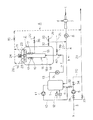
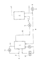
図1及び図2は、本発明に係るガス貯蔵方法を実施するためのガス貯蔵設備の概略構成図である。 FIG.1 and FIG.2 is a schematic block diagram of the gas storage installation for enforcing the gas storage method which concerns on this invention.
図1に示すように、このガス貯蔵設備Aは、反応器1および貯槽兼脱水器兼再ガス化装置2を備えている。
As shown in FIG. 1, the gas storage facility A includes a
この反応器1は、天然ガスハイドレート(以下、ガスハイドレートという。)を生成するため、中圧のガス導管3よりメタンを主体とする天然ガスaを導入し、氷スラリー供給管4より氷スラリーbを導入するようになっている。
The
すなわち、中圧(0.3〜1MPa)の天然ガスaは、ブースターコンプレッサー5によって所定の圧力(例えば、54ata(5.3MPa))に昇圧後、枝管6を経て反応器1に導入される。他方、氷スラリーbは、水cと氷雪dをエダクター7によって混合させたものであり、製造後、氷スラリーポンプ8によって反応器1に導入するようになっている。
That is, the natural gas a having an intermediate pressure (0.3 to 1 MPa) is increased to a predetermined pressure (for example, 54 ata (5.3 MPa)) by the
上記反応器1は、いわゆるバブリング方式の反応器であり、低温(例えば、0℃)の氷スラリーbの中に高圧(54ata(5.3MPa))の天然ガスaを微細な気泡にして噴出することにより、水cと天然ガスaが反応してガスハイドレートが生成される。このガスハイドレートeは、未反応の水を伴ってガスハイドレートスラリーfとなり、ガスハイドレートスラリーポンプ9によって貯槽兼脱水器兼再ガス化装置2に送出される。
The
この反応器1は、その上部と前記枝管6とを結ぶガス循環パイプ10を有しており、未反応の天然ガスaをブロワ11を使って前記枝管6に戻すようになっている。また、この反応器1は、熱交換器12を備えており、氷雪の入手が困難な時期になると、熱交換器12を稼働させてガスハイドレートの生成時に生ずる反応熱を除去するようにしている。
The
貯槽兼脱水器兼再ガス化装置2は、耐圧容器14と、脱水器15と、払出し手段としてのスクレーパ16とを備えている。脱水器15は、管壁の一部にスクリーンなどの濾過部17を有する有底の筒体18と、前記濾過部17の外側に設けたジャケット状の排水部19とを有している。この排水部19には、ガスハイドレートスラリーfから分離した未反応水cを系外に排出する排水管20が接続されている。
The storage tank / dehydrator /
また、この耐圧容器14は、その上端部に中空状の耐圧製のスクレーパ室21を設けており、その中にスクレーパ16を備えている。スクレーパ16は、半径方向に延びる多数の回転翼23を持っており、脱水器15の筒体18の上端から溢れ出るガスハイドレートeを掻き取るようになっている。このスクレーパ室21の底部には、スクレーパ16の回転翼23によって掻き取られたガスハイドレートeを耐圧容器14内に落下させるための開口部(図示せず)が、多数、設けられている。また、スクレーパ室21の上部には、スクレーパ16の回転翼23を回転させるためのモーター24が設けられている。
The
ここで、脱水器15の筒体18の上端がスクレーパ室21の底部に取り付けられていることは言うまでもない。また、上記ガスハイドレートスラリーポンプ9を備えたガスハイドレートスラリー供給管13は、脱水器15の筒体18の底部18aに接続されている。また、このガスハイドレートスラリー供給管13には、注水管25が接続されている。
Here, it goes without saying that the upper end of the
上記耐圧容器14は、その下部側面に余剰水hを排出するための余剰水排水管26を持っており、この余剰水排水管26から分岐した分岐管27は、上記氷スラリー供給管4に接続している。また、上記耐圧容器14は、その上部に再ガス供給管28を設けている。この再ガス供給管28は、ブースターコンプレッサー5の上流側でガス導管3から分岐した中圧のガス導管29に接続している。また、このガス導管29と上記枝管6間には、バイパス管30が設けられている。
The
図中、31、32、33、34、35、36、37、38、39、40は、それぞれ、バルブを示している。
In the figure,
続いて、このガス貯蔵設備の作用について説明する。 Next, the operation of this gas storage facility will be described.
先ず、冬季の運転方法について説明し、その後、夏季(冬季以外の期間)の運転方法について説明する。 First, a driving method in winter will be described, and then a driving method in summer (period other than winter) will be described.
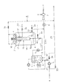
(1)冬季の運転方法
冷熱源としての氷雪がある冬季には、図2に示すように、バルブ31〜33、36及び40を「開」、バルブ34、35、37〜39を「閉」とし、比較的安価な夜間電力を用いて上記ガス貯蔵設備Aを8時間運転する。尚、ガスハイドレート生成条件は、圧力を54ata(5.3MPa)、温度を5℃に設定する。
(1) Winter operation method In winter when there is ice and snow as a cooling source, as shown in FIG. 2,
上記のように、エダクター7によって水cと氷雪dを混合させて造った氷スラリーbを氷スラリーポンプ8によって反応器1に導入し、その量が所定量に達したところで、ブースターコンプレッサー5によって所定の圧力(例えば、54ata(5.3MPa))に昇圧した天然ガスaを上記反応器1内にバブリングさせると、低温(例えば、0℃)の水cと天然ガスaが反応してガスハイドレートeが生成される。
As described above, the ice slurry b formed by mixing the water c and the ice snow d by the
このガスハイドレートeは、ガスハイドレートスラリーポンプ9によって未反応の水cと共に送出され、ガスハイドレートスラリー(例えば、含水率25%)fとなって脱水器15の筒体底部18aに供給される。
This gas hydrate e is sent together with unreacted water c by the gas
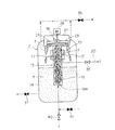
図3に示すように、脱水器15の筒体底部18a供給されたガスハイドレートスラリーfは、脱水器15の筒体18内を上方に向かって上昇する。そして、スクリーンなどの濾過部17に達すると、スクリーンなどの濾過部17によって未反応水cが分離され、その外側の排水部19内に除去される。排水部19内に流出した未反応水cは排水管20を経て系外に排出される。
As shown in FIG. 3, the gas hydrate slurry f supplied to the cylinder bottom 18 a of the
未反応水が除去された粉体状のガスハイドレート(例えば、含水率57%)eは、連続的に供給される後続のガスハイドレートスラリーfによって押し上げられ、脱水器15の筒体18の上端部に達する。脱水器15の筒体18の上端部に達したガスハイドレートeは、スクレーパ16の回転翼23によって掻き取られ、スクレーパ室21の底部に設けた開口部(図示せず)を通って耐圧容器14内に貯蔵される。
The powdery gas hydrate (for example,
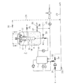
他方、昼間になってガス需要が増加した場合には、図4に示すように、バルブ31、32、34、36、40を「閉」、バルブ35、37、38、39を「開」にした後、注水管25から例えば、12℃程度の水又は温水iを供給する。この水又は温水iは、脱水器15の筒体18の上端から耐圧容器14内に供給される。この水又は温水iによって加温されたガスハイドレートeは、融解して天然ガスaと水cになり、天然ガス(例えば、0.1〜0.3MPa)aは、再ガス供給管28を経て中圧のガス導管29に供給される。
On the other hand, when the gas demand increases during the daytime, as shown in FIG. 4, the
他方、ガスハイドレートeの溶解によって生じた余剰水hは、余剰水排水管26を経て系外に排出される。
On the other hand, surplus water h generated by the dissolution of the gas hydrate e is discharged out of the system through the surplus
(2)夏季(冬季以外)の運転方法
冷熱源としての氷雪のない夏季(冬季以外)の運転方法は、冬季の運転方法と殆ど変わりがないので、詳しい説明を省略する。ただ、この場合には、図示しない冷凍機を運転してガスハイドレートの生成熱(反応熱)を除去するようになっている。
(2) Operation method in summer (other than winter) The operation method in summer (other than winter) without ice and snow as a heat source is almost the same as the operation method in winter, so detailed description is omitted. In this case, however, a refrigerator (not shown) is operated to remove the heat of formation of gas hydrate (reaction heat).
以上の説明では、従来の球形のガスホルダーの代替品としてのガス貯蔵設備について説明したが、この発明は、図5に示すように、大規模コージェネレーションシステムにおけるガス供給系の変動防止にも適用することができる。 In the above description, the gas storage facility as an alternative to the conventional spherical gas holder has been described. However, as shown in FIG. 5, the present invention is also applied to prevent fluctuations in the gas supply system in a large-scale cogeneration system. can do.
この場合には、昼間のガス需要量増加によるガス導管供給圧力低下を防止するため、ガスタービンへ供給するガス量の一部を夜間にガスハイドレートeにしてガス貯蔵設備Aの耐圧容器(図示せず)に貯蔵する。 In this case, in order to prevent a decrease in gas conduit supply pressure due to an increase in gas demand in the daytime, a portion of the amount of gas supplied to the gas turbine is changed to gas hydrate e at night to form a pressure vessel (see FIG. (Not shown).
このコージェネレーションシステムは、ガスタービン50と、発電機51と、廃熱ボイラ52と、温水器53とを備え、ガスタービン50は、吸気冷却器54と、圧縮機55と、燃焼器56と、膨張タービン57により構成されている。
The cogeneration system includes a
そして、再ガス化時に、温水器53で加温した温水iを耐圧容器14に供給し、ガスハイドレートeの再ガス化によって生じた冷水(余剰水)hを循環ポンプ48によって冷却塔補給水等として系外に供給する。その際、吸気冷却器54にて冷水hによる吸気冷却を行い、夏場のガスタービン出力低下を防止する。
At the time of regasification, the hot water i heated by the
また、上記脱水器15は、耐圧容器14の外に設けても差し支えがないが、その場合には、脱水器15に耐圧性を持たせることが必要である。
The
続いて、実施例により本発明を更に詳しく説明する。 Subsequently, the present invention will be described in more detail with reference to examples.
(実施例1)
図6を用いて冬季におけるガスハイドレートの生成、貯蔵及び再ガス化について説明する。この場合は、氷雪の冷熱を利用することにより、補機動力以外の動力(冷凍機動力)が不要となり、経済的である。
(Example 1)
The generation, storage and regasification of the gas hydrate in winter will be described with reference to FIG. In this case, by using the cold heat of ice and snow, power (refrigerator power) other than auxiliary power is not required, which is economical.
(1)ガスハイドレートの生成
(a)ガスハイドレートの生成条件
・圧力:54ata(5.3MPa)
・温度:5℃
(b)原料ガス:メタンを主成分とする天然ガス
・温度:20℃
・供給量:1.0t/h
(c)原料水(氷スラリー)
・温度:0℃
(d)生成器における循環ガス量
・流量:20.0t/h
・温度:5℃
(1) Gas hydrate production (a) Gas hydrate production conditions
・ Pressure: 54ata (5.3MPa)
・ Temperature: 5 ℃
(B) Source gas: Natural gas mainly composed of methane
・ Temperature: 20 ℃
・ Supply amount: 1.0t / h
(C) Raw material water (ice slurry)
・ Temperature: 0 ℃
(D) Circulating gas amount in the generator
・ Flow rate: 20.0t / h
・ Temperature: 5 ℃
この結果、生成器1によって濃度25%、5℃の天然ガスハイドレートスラリーを31.9t/h生成することができた。尚、その内訳は、天然ガスハイドレート8.0t/h(含むメタン1.0t/h)、水23.9t/hである。
As a result, the
続いて、この天然ガスハイドレートスラリーを図示しない脱水器に供給して脱水したところ、濃度57%の天然ガスハイドレートを13.9t/h製造することができた。その内訳は、天然ガスハイドレート8.0t/h(含むメタン1.0t/h)、水5.9t/hである。 Subsequently, when this natural gas hydrate slurry was supplied to a dehydrator (not shown) for dehydration, natural gas hydrate having a concentration of 57% could be produced at 13.9 t / h. The breakdown is natural gas hydrate 8.0 t / h (including methane 1.0 t / h) and water 5.9 t / h.
ここで、夜間電力を用いて8時間連続運転すると、天然ガスハイドレートの生成量は、111.2tとなることから、天然ガスハイドレートの比重を0.8と仮定した場合、天然ガスハイドレートの容積は、139m3 となる。これを球形の圧力容器に貯蔵すると仮定すると、球形の圧力容器の直径は、約6mとなり、従来の半分以下になる。 Here, when the operation is continued for 8 hours using nighttime power, the amount of natural gas hydrate produced is 111.2 t. Therefore, when the specific gravity of the natural gas hydrate is assumed to be 0.8, the natural gas hydrate is The volume of is 139 m 3 . Assuming that this is stored in a spherical pressure vessel, the diameter of the spherical pressure vessel is about 6 m, which is less than half the conventional one.
既に説明したように、天然ガスを球形のガスホルダーに1t/hの割合で8時間貯蔵する場合には、球形のガスホルダーの直径は、約15mである。 As already explained, when natural gas is stored in a spherical gas holder at a rate of 1 t / h for 8 hours, the diameter of the spherical gas holder is about 15 m.
(2)ガスハイドレートの再ガス化
ガス需要時に耐圧容器14内の天然ガスハイドレートを再ガス化したところ、天然ガスが2t/h、5℃の水が25.8t/h得られた(4時間で再ガス化の場合。)。
(2) was re-gasified natural gas hydrate of the
(実施例2)
図7を用いて夏季(冬季以外)におけるガスハイドレートの生成、貯蔵及び再ガス化について説明する。この場合は、冷凍機を運転するため、140kWh/t(CH4軸基準)の電力が必要となる。
(Example 2)
The generation, storage, and regasification of gas hydrate in summer (other than winter) will be described with reference to FIG. In this case, in order to operate the refrigerator, 140 kWh / t (CH4 axis reference) is required.
(1)ガスハイドレートの生成
(a)ガスハイドレートの生成条件
・圧力:54ata(5.3MPa)
・温度:5℃
(b)原料ガス:メタンを主成分とする天然ガス
・温度:20℃
・供給量:1.0t/h
(c)原料水(水)
・温度:20℃
(d)生成器における循環ガス量
・流量:20.0t/h
・温度:5℃
(e)生成器における循環水の温度
・熱交換器入口:5℃
・熱交換器出口:2℃
(1) Gas hydrate production (a) Gas hydrate production conditions
・ Pressure: 54ata (5.3MPa)
・ Temperature: 5 ℃
(B) Source gas: Natural gas mainly composed of methane
・ Temperature: 20 ℃
・ Supply amount: 1.0t / h
(C) Raw material water (water)
・ Temperature: 20 ℃
(D) Circulating gas amount in the generator
・ Flow rate: 20.0t / h
・ Temperature: 5 ℃
(E) Temperature of circulating water in the generator
・ Heat exchanger inlet: 5 ℃
-Heat exchanger outlet: 2 ° C
この結果、生成器1によって濃度25%、温度5℃の天然ガスハイドレートスラリーを31.9t/h生成することができた。尚、その内訳は、天然ガスハイドレート8.0t/h(含むメタン1.0t/h)、水23.9t/hである。
As a result, the
続いて、この天然ガスハイドレートスラリーを脱水器(図示せず)に供給して脱水したところ、濃度57%の天然ガスハイドレートを13.9t/h製造することができた。その内訳は、天然ガスハイドレート8.0t/h(含むメタン1.0t/h)、水5.9t/hである。 Subsequently, when this natural gas hydrate slurry was supplied to a dehydrator (not shown) and dehydrated, natural gas hydrate having a concentration of 57% could be produced at 13.9 t / h. The breakdown is natural gas hydrate 8.0 t / h (including methane 1.0 t / h) and water 5.9 t / h.
(2)ガスハイドレートの再ガス化
ガス需要時に耐圧容器14内の天然ガスハイドレートを再ガス化したところ、天然ガスが2t/h、5℃の水が25.8t/h得られた(4時間で再ガス化の場合。)。
(2) was re-gasified natural gas hydrate of the
a メタンを主体とするガス
c 水
e ガスハイドレート
f ガスハイドレートスラリー
i 水
14 耐圧容器
15 脱水器
16 払出し手段
17 濾過部
a Gas mainly composed of methane c Water e Gas hydrate f Gas hydrate
Claims (5)
5. The gas storage method according to claim 4, wherein surplus water generated at the time of regasification of the gas hydrate is supplied to an intake air cooler of the gas turbine to prevent a decrease in gas turbine output.
Priority Applications (1)
| Application Number | Priority Date | Filing Date | Title |
|---|---|---|---|
| JP2004119835A JP4575700B2 (en) | 2004-04-15 | 2004-04-15 | Gas storage method |
Applications Claiming Priority (1)
| Application Number | Priority Date | Filing Date | Title |
|---|---|---|---|
| JP2004119835A JP4575700B2 (en) | 2004-04-15 | 2004-04-15 | Gas storage method |
Publications (2)
| Publication Number | Publication Date |
|---|---|
| JP2005298745A true JP2005298745A (en) | 2005-10-27 |
| JP4575700B2 JP4575700B2 (en) | 2010-11-04 |
Family
ID=35330676
Family Applications (1)
| Application Number | Title | Priority Date | Filing Date |
|---|---|---|---|
| JP2004119835A Expired - Fee Related JP4575700B2 (en) | 2004-04-15 | 2004-04-15 | Gas storage method |
Country Status (1)
| Country | Link |
|---|---|
| JP (1) | JP4575700B2 (en) |
Cited By (7)
| Publication number | Priority date | Publication date | Assignee | Title |
|---|---|---|---|---|
| JP2007224116A (en) * | 2006-02-22 | 2007-09-06 | Mitsui Eng & Shipbuild Co Ltd | Gas hydrate dehydrator |
| JP2007238836A (en) * | 2006-03-10 | 2007-09-20 | Mitsui Eng & Shipbuild Co Ltd | Dehydrator in natural gas hydrate production plant |
| JP2007238826A (en) * | 2006-03-10 | 2007-09-20 | Mitsui Eng & Shipbuild Co Ltd | Method and apparatus for generating gas hydrate |
| JP2007238837A (en) * | 2006-03-10 | 2007-09-20 | Mitsui Eng & Shipbuild Co Ltd | Dehydrator in natural gas hydrate production plant |
| US20130158306A1 (en) * | 2010-08-23 | 2013-06-20 | Daewoo Enginerring & Construction Co., Ltd. | Device and method for manufacturing natural gas hydrate |
| WO2015087767A1 (en) | 2013-12-09 | 2015-06-18 | 独立行政法人産業技術総合研究所 | Subsampling device and method |
| US10179884B2 (en) * | 2013-02-22 | 2019-01-15 | Daewoo Engineering & Construction Co., Ltd. | Device and method for manufacturing natural gas hydrate |
Citations (8)
| Publication number | Priority date | Publication date | Assignee | Title |
|---|---|---|---|---|
| JPH0538429A (en) * | 1991-08-07 | 1993-02-19 | Mitsubishi Heavy Ind Ltd | Treatment of carbon dioxide |
| JPH0949600A (en) * | 1995-05-31 | 1997-02-18 | Osaka Gas Co Ltd | Storing and sending out method for natural gas and device therefor |
| JP2001072615A (en) * | 1999-09-01 | 2001-03-21 | Ishikawajima Harima Heavy Ind Co Ltd | Hydrate manufacturing method and its manufacturing apparatus |
| JP2001342473A (en) * | 2000-03-30 | 2001-12-14 | Mitsubishi Heavy Ind Ltd | Apparatus for producing gas hydrate and apparatus for dehydrating gas hydrate |
| JP2003082370A (en) * | 2001-09-11 | 2003-03-19 | Mitsui Eng & Shipbuild Co Ltd | Natural gas storage system |
| JP2003227600A (en) * | 2002-02-04 | 2003-08-15 | Mitsubishi Heavy Ind Ltd | Natural gas supplying method |
| JP2004010686A (en) * | 2002-06-05 | 2004-01-15 | Mitsui Eng & Shipbuild Co Ltd | Gas hydrate generation apparatus, production apparatus and production method |
| JP2005248124A (en) * | 2004-03-08 | 2005-09-15 | Chubu Electric Power Co Inc | Method and apparatus for manufacturing gas hydrate |
-
2004
- 2004-04-15 JP JP2004119835A patent/JP4575700B2/en not_active Expired - Fee Related
Patent Citations (8)
| Publication number | Priority date | Publication date | Assignee | Title |
|---|---|---|---|---|
| JPH0538429A (en) * | 1991-08-07 | 1993-02-19 | Mitsubishi Heavy Ind Ltd | Treatment of carbon dioxide |
| JPH0949600A (en) * | 1995-05-31 | 1997-02-18 | Osaka Gas Co Ltd | Storing and sending out method for natural gas and device therefor |
| JP2001072615A (en) * | 1999-09-01 | 2001-03-21 | Ishikawajima Harima Heavy Ind Co Ltd | Hydrate manufacturing method and its manufacturing apparatus |
| JP2001342473A (en) * | 2000-03-30 | 2001-12-14 | Mitsubishi Heavy Ind Ltd | Apparatus for producing gas hydrate and apparatus for dehydrating gas hydrate |
| JP2003082370A (en) * | 2001-09-11 | 2003-03-19 | Mitsui Eng & Shipbuild Co Ltd | Natural gas storage system |
| JP2003227600A (en) * | 2002-02-04 | 2003-08-15 | Mitsubishi Heavy Ind Ltd | Natural gas supplying method |
| JP2004010686A (en) * | 2002-06-05 | 2004-01-15 | Mitsui Eng & Shipbuild Co Ltd | Gas hydrate generation apparatus, production apparatus and production method |
| JP2005248124A (en) * | 2004-03-08 | 2005-09-15 | Chubu Electric Power Co Inc | Method and apparatus for manufacturing gas hydrate |
Cited By (11)
| Publication number | Priority date | Publication date | Assignee | Title |
|---|---|---|---|---|
| JP2007224116A (en) * | 2006-02-22 | 2007-09-06 | Mitsui Eng & Shipbuild Co Ltd | Gas hydrate dehydrator |
| JP2007238836A (en) * | 2006-03-10 | 2007-09-20 | Mitsui Eng & Shipbuild Co Ltd | Dehydrator in natural gas hydrate production plant |
| JP2007238826A (en) * | 2006-03-10 | 2007-09-20 | Mitsui Eng & Shipbuild Co Ltd | Method and apparatus for generating gas hydrate |
| JP2007238837A (en) * | 2006-03-10 | 2007-09-20 | Mitsui Eng & Shipbuild Co Ltd | Dehydrator in natural gas hydrate production plant |
| US20130158306A1 (en) * | 2010-08-23 | 2013-06-20 | Daewoo Enginerring & Construction Co., Ltd. | Device and method for manufacturing natural gas hydrate |
| JP2013540706A (en) * | 2010-08-23 | 2013-11-07 | ドングク・ユニヴァーシティー・インダストリー−アカデミック・コーオペレーション・ファンデーション | Natural gas hydrate manufacturing apparatus and natural gas hydrate manufacturing method |
| US9255234B2 (en) | 2010-08-23 | 2016-02-09 | Dongguk University Industry-Academic Cooperation Foundation | Device and method for manufacturing natural gas hydrate |
| US10179884B2 (en) * | 2013-02-22 | 2019-01-15 | Daewoo Engineering & Construction Co., Ltd. | Device and method for manufacturing natural gas hydrate |
| WO2015087767A1 (en) | 2013-12-09 | 2015-06-18 | 独立行政法人産業技術総合研究所 | Subsampling device and method |
| KR20160083065A (en) | 2013-12-09 | 2016-07-11 | 고쿠리츠켄큐카이하츠호진 상교기쥬츠 소고켄큐쇼 | Subsampling device and method |
| US10101245B2 (en) | 2013-12-09 | 2018-10-16 | National Institute Of Advanced Industrial Science And Technology | Subsampling device and method |
Also Published As
| Publication number | Publication date |
|---|---|
| JP4575700B2 (en) | 2010-11-04 |
Similar Documents
| Publication | Publication Date | Title |
|---|---|---|
| KR101495221B1 (en) | Device and method for manufacturing natural gas hydrate | |
| US9488160B2 (en) | Dispatchable power plant and method for using the same | |
| CN103571557B (en) | Method for preparing natural gas hydrate | |
| JP4594949B2 (en) | Natural gas hydrate cracking gas and fresh water supply facility | |
| CN106837258B (en) | A kind of gas hydrate exploitation device and method | |
| US20110138810A1 (en) | Apparatus for producing power using geothermal liquid | |
| CN103059899A (en) | Systems, methods, and compositions for production of synthetic hydrocarbon compounds | |
| CN109386316A (en) | A kind of LNG cold energy and BOG Combustion Energy joint utilize system and method | |
| JP4575700B2 (en) | Gas storage method | |
| Li et al. | Effects of initial pressure and gas-water ratio on the CO2 hydrate-based cold thermal energy storage under the gas-inducing agitation | |
| JP4554641B2 (en) | Methane hydrate cold power generation system | |
| US10179884B2 (en) | Device and method for manufacturing natural gas hydrate | |
| JP2001010989A (en) | Methane hydrate production apparatus and production method | |
| CN102322414B (en) | Air compressor set capable of recovering and storing interstage cold and heat energy in high-quality manner | |
| JPH0949600A (en) | Storing and sending out method for natural gas and device therefor | |
| CN111234873A (en) | A supercritical water gasification system and method for energy recovery and zero discharge of waste water | |
| KR102478612B1 (en) | Apparatus for CO2 hydrate generating and storing and Method for same the using | |
| CN108661765A (en) | A kind of automobile engine tail gas waste-heat recycling efficient power generation system | |
| JP4080351B2 (en) | Gas hydrate production and storage method | |
| CN102889471B (en) | Centralized gas supply station for pipeline special for civil dimethyl ether gas and gas supply method thereof | |
| JP4313603B2 (en) | Heat storage system using gas hydrate | |
| RU2541354C1 (en) | Plant for gas production out of gas hydrate | |
| KR102342162B1 (en) | Gas Hydrate based Seawater Desalination Apparatus of Waste Heat Recovery type and method thereof | |
| JP2003082370A (en) | Natural gas storage system | |
| JP2001010988A (en) | Method for producing methane hydrate |
Legal Events
| Date | Code | Title | Description |
|---|---|---|---|
| A621 | Written request for application examination |
Free format text: JAPANESE INTERMEDIATE CODE: A621 Effective date: 20070329 |
|
| A977 | Report on retrieval |
Free format text: JAPANESE INTERMEDIATE CODE: A971007 Effective date: 20100519 |
|
| A131 | Notification of reasons for refusal |
Free format text: JAPANESE INTERMEDIATE CODE: A131 Effective date: 20100525 |
|
| A521 | Written amendment |
Free format text: JAPANESE INTERMEDIATE CODE: A523 Effective date: 20100722 |
|
| TRDD | Decision of grant or rejection written | ||
| A01 | Written decision to grant a patent or to grant a registration (utility model) |
Free format text: JAPANESE INTERMEDIATE CODE: A01 Effective date: 20100810 |
|
| A01 | Written decision to grant a patent or to grant a registration (utility model) |
Free format text: JAPANESE INTERMEDIATE CODE: A01 |
|
| A61 | First payment of annual fees (during grant procedure) |
Free format text: JAPANESE INTERMEDIATE CODE: A61 Effective date: 20100820 |
|
| R150 | Certificate of patent (=grant) or registration of utility model |
Free format text: JAPANESE INTERMEDIATE CODE: R150 |
|
| FPAY | Renewal fee payment (prs date is renewal date of database) |
Free format text: PAYMENT UNTIL: 20130827 Year of fee payment: 3 |
|
| FPAY | Renewal fee payment (prs date is renewal date of database) |
Free format text: PAYMENT UNTIL: 20140827 Year of fee payment: 4 |
|
| LAPS | Cancellation because of no payment of annual fees |