JP2005298029A - Packaging box - Google Patents
Packaging box Download PDFInfo
- Publication number
- JP2005298029A JP2005298029A JP2004119184A JP2004119184A JP2005298029A JP 2005298029 A JP2005298029 A JP 2005298029A JP 2004119184 A JP2004119184 A JP 2004119184A JP 2004119184 A JP2004119184 A JP 2004119184A JP 2005298029 A JP2005298029 A JP 2005298029A
- Authority
- JP
- Japan
- Prior art keywords
- flap
- packaging box
- lid
- lid flap
- cylindrical body
- Prior art date
- Legal status (The legal status is an assumption and is not a legal conclusion. Google has not performed a legal analysis and makes no representation as to the accuracy of the status listed.)
- Pending
Links
Images

Landscapes
- Cartons (AREA)
Abstract
Description
本発明は、包装箱に関するものである。 The present invention relates to a packaging box.
従来より、4つの長方形状の側壁部、下蓋部、及び上蓋部からなる略直方体の段ボール紙製の包装箱が知られており、その下蓋部は、側壁部の各下辺に連接された4つの略長方形状のフラップによって形成されている。 Conventionally, a substantially rectangular parallelepiped corrugated cardboard packaging box composed of four rectangular side walls, a lower lid, and an upper lid is known, and the lower lid is connected to each lower side of the side wall. It is formed by four substantially rectangular flaps.
そして、この種の包装箱としては、以下に示す構成をしたものがある。
まず、4つのフラップのうち、互いに向かい合う一組のフラップの各々には、当該フラップの辺のうちの側壁部の下辺に垂直な一対の辺の各々から当該フラップの内部へ延びた切目が形成されている。そして、そのフラップの上記切目よりも先端側の部分は、その切目の両端のうちの上記内部側の端から当該フラップの先端に向かって形成された折目で折り曲げることが可能な一対の差込片となっている。
And as this kind of packaging box, there exists what comprised the structure shown below.
First, each of a pair of flaps facing each other among the four flaps is formed with a cut extending from each of a pair of sides perpendicular to the lower side of the side wall portion of the sides of the flap to the inside of the flap. ing. And the part of the front end side rather than the cut of the flap is a pair of insertions that can be bent at the fold formed from the inner end of the cut toward the front end of the flap. It is a piece.
また、他の向かい合う一組のフラップの各々には、上記差込片が挿入される切込が形成されている。
以上のような構成の包装箱では、まず、上記切込が形成された方のフラップを側壁部の下辺で箱の内側方向へ折り曲げる。次いで、上記差込片を有した方のフラップを同様に折り曲げると共に、その各フラップにおける差込片の各々を、上記折目で先に折り曲げられた一対のフラップ方向へ折り曲げて、先に折り曲げられたフラップの切込のうち、その差込片に対応した切込にそれぞれ挿入することにより下蓋部を作成することができる。
Moreover, the notch into which the said insertion piece is inserted is formed in each of a pair of other facing flaps.
In the packaging box having the above-described configuration, first, the flap on which the cut is formed is bent toward the inside of the box at the lower side of the side wall. Next, the flap having the insertion piece is bent in the same manner, and each of the insertion pieces in each of the flaps is bent in a pair of flap directions which are bent first by the fold, and then bent first. The lower lid part can be created by inserting each of the cuts in the flap into the cuts corresponding to the inserted pieces.
そして、このような包装箱によれば、収納物を当該包装箱に収納した際に、その収納物の重みにより差込片が押し下げられて、該差込片が、切込を有した方のフラップにおける包装箱の内側の面に引っ掛かることとなり、下蓋部の解体(底抜け)を防止することができる(例えば、特許文献1参照)。
しかしながら、従来の包装箱では、下蓋部の作成作業を行う際に、2つの各フラップの一対の差込片を他のフラップの切込に注意深く意識して挿入しなければならないため、下蓋部の作成作業に手間がかかってしまう。尚、上記包装箱の下蓋部の構成を同包装箱の上蓋部に適用した場合も、同様の問題が生じる。 However, in the conventional packaging box, when making the lower lid portion, the pair of insertion pieces of each of the two flaps must be carefully inserted into the cuts of the other flaps. It takes time to create the department. The same problem arises when the structure of the lower lid portion of the packaging box is applied to the upper lid portion of the packaging box.
本発明は、上記問題を解決するためになされたものであり、作成された蓋部が容易に解体してしまうのを防止すると共に、従来品よりも蓋部の作成作業の効率が高い包装箱を提供することを目的としている。 The present invention has been made to solve the above-described problem, and prevents the created lid part from being easily disassembled, and has a higher efficiency in creating the lid part than the conventional product. The purpose is to provide.
上記目的を達成するためになされた請求項1に記載の包装箱は、4つの長方形状の側壁からなる筒体部と、該筒体部の一方の端部における互いに向かい合う2組の辺のうちの1組の辺にそれぞれ連接された第1蓋用フラップ及び第3蓋用フラップと、筒体部の2組の辺のうちの他方の1組の辺にそれぞれ連接された第2蓋用フラップ及び第4蓋用フラップと、を備えている。
The packaging box according to
そして、この包装箱では、第1〜第4蓋用フラップの各々が筒体部と連接している各辺で筒体部の内側方向へ折り曲げられることにより、該筒体部の上記端部側の開口全体又は一部を覆う蓋部が構成されるようになっている。 In this packaging box, each of the first to fourth lid flaps is bent inwardly of the cylindrical portion at each side connected to the cylindrical portion, so that the end portion side of the cylindrical portion is provided. A lid that covers all or part of the opening is configured.
ここで特に、第1,第3蓋用フラップのうちの少なくとも一方には、第2蓋用フラップにおける先端側の両方の隅部及び第4蓋用フラップにおける先端側の両方の隅部のうちの少なくとも一つが折り曲げられることなくそのまま挿入される挿入口が形成されている。 Here, in particular, at least one of the first and third lid flaps includes both of the corners on the tip side of the second lid flap and the corners on both sides of the tip side of the fourth lid flap. An insertion slot is formed in which at least one is inserted without being bent.
そして更に、上記挿入口に挿入される隅部(以下、挿入用隅部という)を有する蓋用フラップには、該挿入用隅部にて挿入口に挿入される挿入部分の筒体部側の端に沿って切り欠きが形成され、挿入部分が挿入口に挿入されている状態(即ち、蓋部が作成された状態)では、挿入部分における切り欠き側の端が、挿入口の縁のうち、挿入部分が挿入されてくる方向の上流側の縁に引っ掛かるようになっている。 Further, the lid flap having a corner portion (hereinafter referred to as an insertion corner portion) to be inserted into the insertion port has a cylindrical portion side of the insertion portion to be inserted into the insertion port at the insertion corner portion. In a state where a notch is formed along the end and the insertion portion is inserted into the insertion port (that is, the lid is created), the end on the notch side of the insertion portion is out of the edge of the insertion port. The insertion portion is caught on the upstream edge in the direction in which the insertion portion is inserted.
このような請求項1の包装箱によれば、従来の包装箱とは異なり、上記差込片が存在しないため、蓋部の作成作業を行う際に、挿入部分を意識しなくても良い。従って、蓋部の作成作業を容易に且つ迅速に実施することができる。
According to such a packaging box of
しかも、挿入部分が挿入口に挿入されている状態では、挿入部分の切り欠き側の端と挿入口の上流側の縁とが引っ掛かることなるため、蓋部が簡単に解体してしまうことを防止することができる。 Moreover, when the insertion part is inserted into the insertion port, the notch side end of the insertion part and the upstream edge of the insertion port are caught, preventing the lid from being easily disassembled. can do.
ところで、本包装箱の蓋部を下蓋部(底部)として用いる場合は、底抜けを防ぐために蓋部をより強固に保持するように構成することが好ましい。
この場合、第1〜第4蓋用フラップは以下の構成を採ることが考えられる。
By the way, when using the cover part of this packaging box as a lower cover part (bottom part), it is preferable to comprise so that a cover part may be hold | maintained more firmly in order to prevent bottom omission.
In this case, the first to fourth lid flaps may be configured as follows.
まず、第1蓋用フラップには、第2蓋用フラップにおける上記両方の隅部のうちの一方が折り曲げられることなく挿入される挿入口と、第4蓋用フラップにおける上記両方の隅部のうちの一方が折り曲げられることなく挿入される挿入口と、が形成されている。 First, the first lid flap has an insertion slot into which one of the two corners of the second lid flap is inserted without being bent, and the both of the corners of the fourth lid flap. And an insertion slot into which one of the two is inserted without being bent.
そして、第3蓋用フラップには、第2蓋用フラップにおける両方の隅部のうちの他方が折り曲げられることなく挿入される挿入口と、第4蓋用フラップにおける両方の隅部のうちの他方が折り曲げられることなく挿入される挿入口と、が形成されている。 The third lid flap has an insertion slot into which the other of both corners of the second lid flap is inserted without being bent, and the other of both corners of the fourth lid flap. Is formed without being bent.
また、第2,第4蓋用フラップには、各挿入部分の筒体部側の端に沿って切り欠きが形成されている。
つまり、このように構成された包装箱では、第2,第4蓋用フラップが挿入用隅部を有した蓋用フラップであり、且つ、第2,第4蓋用フラップの各々の両方の隅部が挿入用隅部である。
Further, the second and fourth lid flaps are formed with cutouts along the ends of the respective insertion portions on the cylindrical body side.
That is, in the packaging box configured in this way, the second and fourth lid flaps are lid flaps having insertion corners, and both corners of the second and fourth lid flaps are provided. The part is an insertion corner.
そして、請求項1の包装箱が上述の構成を採っていれば、第1,第3蓋用フラップを筒体部に連接している辺で該筒体部の内側方向へ折り曲げてから、第2,第4蓋用フラップを同様に折り曲げると共に各挿入部分を該挿入部分に対応する挿入口に挿入するだけで蓋部を作成することができる。
And if the packaging box of
次に、請求項2に記載の包装箱は、請求項1の包装箱において、挿入口が形成された蓋用フラップに、挿入口の上記上流側の縁(即ち、挿入部分の切り欠き側の端に引っ掛かることとなる縁)から延びた切目が形成されている。 Next, a packaging box according to a second aspect is the packaging box according to the first aspect, wherein the upstream side edge of the insertion port (that is, the notch side of the insertion portion) is placed on the lid flap formed with the insertion port. An incision extending from the edge that is hooked to the end is formed.
そして、請求項2の包装箱では、挿入部分が挿入口に挿入されている状態で、挿入口が形成された蓋用フラップにて、上記切目と当該蓋用フラップの筒体部と連接している辺との間の部分が筒体部の内側へ押し込まれることにより、挿入部分の切り欠き側の端と挿入口の上記上流側の縁との引っ掛かりが解除されるようになっている。
And in the packaging box of
このため、蓋部を解体する際には、上述の如く挿入部分の端と挿入口の縁との引っ掛かりを解除してから、挿入部分を挿入口から抜き出すだけで蓋部を解体することができる。
また、請求項1又は請求項2の包装箱において、請求項3に記載の如く、挿入用隅部を有する蓋用フラップには、当該蓋用フラップの筒体部と連接している辺に平行な折目が形成されていれば、当該蓋用フラップを折目で山状に折り曲げてから、挿入口に挿入することができる。
For this reason, when disassembling the lid portion, the lid portion can be disassembled by simply removing the insertion portion from the insertion port after releasing the hook between the end of the insertion portion and the edge of the insertion port as described above. .
Further, in the packaging box according to
従って、請求項3の包装箱によれば、更に、蓋部の作成作業を容易に実施することができる。
ところで、請求項1〜請求項3の包装箱において、請求項4に記載の如く、材質が段ボール箱であれば、重量を軽くすることができると共に、充分な強度を確保することができる。また、包装箱自体を安価に製造しやすいという利点もある。
Therefore, according to the packaging box of the third aspect, it is possible to easily perform the operation of creating the lid.
By the way, in the packaging box according to
以下に、本発明が適用された実施形態の包装箱について、図面を用いて説明する。尚、本実施形態の包装箱は、主に果物や野菜等の農産物(例えば、ホウレンソウやレタス)を搬送する際に該農産物を収納して使用されるものである。 Below, the packaging box of embodiment to which this invention was applied is demonstrated using drawing. The packaging box of the present embodiment is mainly used for storing agricultural products such as fruits and vegetables (for example, spinach and lettuce) when transporting the agricultural products.
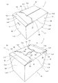
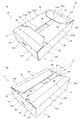
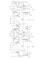
まず図1は、第1実施形態の包装箱1の組立状態における斜視図であり、同図(a)は上蓋部10を上側、同図(b)は下側(つまり、下蓋部11を上側)としている。また、図2は、同包装箱1の展開状態における平面図である。
First, FIG. 1 is a perspective view of the
包装箱1は、段ボール製のシート材からなり、図2に示すような形状に裁断されている。尚、以下の説明において、上下左右縦横等、方向に関する表現は、図2における方向である。そして、破線で示す箇所は、折り曲げやすいように折目やミシン目が形成されている。また、一点鎖線で示す箇所は透過状態を表している。
The
図2に示すように、裁断された包装箱1は、長方形の第1〜第4側壁部S1,S2,S3,S4と、第1〜第4側壁部S1〜S4の各下辺Lu1,Lu2,Lu3,Lu4に連接されている第1〜第4下フラップFu1,Fu2,Fu3,Fu4と、第1〜第4側壁部S1〜S4の各上辺Lo1,Lo2,Lo3,Lo4に連接されている第1〜第4上フラップFo1,Fo2,Fo3,Fo4と、によって形成されている。
As shown in FIG. 2, the
また、組立状態においては、第1〜第4側壁部S1〜S4によって包装箱1における4方の側壁(筒体部に相当)12が構成され、第1〜第4下フラップFu1〜Fu4によって下蓋部11が構成され、第1〜第4上フラップFo1〜Fo4によって上蓋部10が構成されるようになっている。
Further, in the assembled state, the first to fourth side wall portions S1 to S4 constitute four side walls (corresponding to the cylindrical body portion) 12 in the
そして、第1〜第4側壁部S1〜S4は、それらの上辺Lo1〜Lo4または下辺Lu1〜Lu4が一直線上に並んだ状態となる図2の展開状態において、左側からS1→S2→S3→S4の順に形成されている。尚、第1側壁部S1の辺のうち、第2側壁部S2側とは反対側の辺には、第1側壁部S1と第4側壁部S4とを接合し、側壁12を形成するための接合代20が連接されている。
And the 1st-4th side wall part S1-S4 is S1-> S2-> S3-> S4 from the left side in the expansion | deployment state of FIG. 2 where those upper sides Lo1-Lo4 or those lower sides Lu1-Lu4 are located in a straight line. Are formed in this order. Of the sides of the first side wall S1, the side opposite to the second side wall S2 side is joined with the first side wall S1 and the fourth side wall S4 to form the
次に、第1〜第4側壁部S1〜S4、第1〜第4下フラップFu1〜Fu4、及び、第1〜第4上フラップFo1〜Fo4の構成について説明する。
まず、第1〜第4側壁部S1〜S4の構成について説明する。
Next, the configuration of the first to fourth side wall portions S1 to S4, the first to fourth lower flaps Fu1 to Fu4, and the first to fourth upper flaps Fo1 to Fo4 will be described.
First, the structure of 1st-4th side wall part S1-S4 is demonstrated.
第1側壁部S1は、互いに平行な上辺Lo1及び下辺Lu1と、その上辺Lo1及び下辺Lu1に垂直で且つそれらより短い一対の辺と、からなる長方形に形成されている。
そして、第3側壁部S3は、第1側壁部S1と合同である。
The first side wall portion S1 is formed in a rectangular shape including an upper side Lo1 and a lower side Lu1 that are parallel to each other, and a pair of sides that are perpendicular to and shorter than the upper side Lo1 and the lower side Lu1.
And 3rd side wall part S3 is congruent with 1st side wall part S1.
また、第2側壁部S2は、互いに平行な上辺Lo2及び下辺Lu2と、その上辺Lo2及び下辺Lu2に垂直で且つそれらより長い一対の辺と、からなる長方形に形成されている。更に、上辺Lo2及び下辺Lu2の長さは、第1側壁部S1の上辺Lo1及び下辺Lu1の長さよりも短い。 Further, the second side wall portion S2 is formed in a rectangular shape including an upper side Lo2 and a lower side Lu2 that are parallel to each other, and a pair of sides that are perpendicular to the upper side Lo2 and the lower side Lu2 and are longer than those. Furthermore, the lengths of the upper side Lo2 and the lower side Lu2 are shorter than the lengths of the upper side Lo1 and the lower side Lu1 of the first side wall portion S1.
そして、第4側壁部S4は、第2側壁部S2と合同である。
更に、第1〜第4側壁部S1〜S4にて、上辺Lo1〜Lo4及び下辺Lu1〜Lu4に垂直な辺の長さは、全ての側壁部S1〜S4で等しい。
And 4th side wall part S4 is congruent with 2nd side wall part S2.
Further, in the first to fourth side wall portions S1 to S4, the lengths of the sides perpendicular to the upper side Lo1 to Lo4 and the lower side Lu1 to Lu4 are the same in all the side wall portions S1 to S4.
尚、第2,第4側壁部S2,S4の各々には、当該側壁部S2,S4の中央部分よりもその上辺Lo2,Lo4側に楕円形の穴h1,h2がそれぞれ形成されている。
次に、第1〜第4下フラップFu1〜Fu4の構成について説明する。
In each of the second and fourth side wall portions S2 and S4, elliptic holes h1 and h2 are formed on the upper side Lo2 and Lo4 side of the central portion of the side wall portions S2 and S4, respectively.
Next, the configuration of the first to fourth lower flaps Fu1 to Fu4 will be described.
第2下フラップFu2は、第2側壁部S2の下辺Lu2と、その下辺Lu2に平行で且つ同じ長さの辺L1と、それら2つの辺Lu2,L1に垂直で且つそれらよりも短い一対の辺L2,L3と、からなる長方形に形成されている。 The second lower flap Fu2 includes a lower side Lu2 of the second side wall portion S2, a side L1 parallel to the lower side Lu2 and having the same length, and a pair of sides perpendicular to and shorter than the two sides Lu2 and L1. It is formed in the rectangle which consists of L2, L3.
そして、第2下フラップFu2には、当該第2下フラップFu2の辺Lu2,L1,L2,L3のうち、第1下フラップFu1側の辺L2を分断するように切り欠きC1が形成されていると共に、第3下フラップFu3側の辺L3を分断するように切り欠きC2が形成されている。尚、切り欠きC2は、切り欠きC1と合同であり、その切り欠きC1を第2側壁部S2の下辺Lu2の垂直二等分線に関して線対称移動させた位置及び形状に形成されている。 A cutout C1 is formed in the second lower flap Fu2 so as to divide the side L2 on the first lower flap Fu1 side among the sides Lu2, L1, L2, and L3 of the second lower flap Fu2. At the same time, a notch C2 is formed so as to divide the side L3 on the third lower flap Fu3 side. The notch C2 is congruent with the notch C1, and is formed in a position and shape in which the notch C1 is line-symmetrically moved with respect to the perpendicular bisector of the lower side Lu2 of the second side wall portion S2.
更に、第2下フラップFu2における先端側(辺L1側)の両方の隅部21,23のうち、辺L2側(切り欠きC1側)の隅部21が、第1下フラップFu1の後述する第1挿入口H1に折り曲げられることなく挿入されるようになっていると共に、辺L3側(切り欠きC2側)の隅部23が、第3下フラップFu3の後述する第2挿入口H2に折り曲げられることなく挿入されるようになっている。
Further, of both
そして更に、包装箱1が図1の如く組立状態にある場合では、上記切り欠きC1側の隅部21のうちの第1挿入口H1に挿入される挿入部分24にて、切り欠きC1側の端25が、第1挿入口H1の縁のうち、第2下フラップFu2側の縁37に引っ掛かるようになっていると共に、上記切り欠きC2側の隅部23のうちの第2挿入口H2に挿入される挿入部分26にて、切り欠きC2側の端27が、第2挿入口H2の縁のうち、第2下フラップFu2側の縁39に引っ掛かるようになっている。
Further, when the
また更に、第2下フラップFu2には、第2側壁部S2の下辺Lu2に平行な折目T1が上記切り欠きC1,C2よりも第2側壁部S2側に形成されている。
また、第4下フラップFu4は、第2下フラップFu2と合同である。即ち、第4下フラップFu4にも第2下フラップFu2の切り欠きC1,C2及び折目T1と同様の切り欠きC3,C4及び折目T2が形成されている。
Furthermore, a fold T1 parallel to the lower side Lu2 of the second side wall portion S2 is formed in the second lower flap Fu2 on the second side wall portion S2 side with respect to the notches C1 and C2.
The fourth lower flap Fu4 is congruent with the second lower flap Fu2. That is, notches C3, C4 and folds T2 similar to the notches C1, C2 and folds T1 of the second lower flap Fu2 are formed in the fourth lower flap Fu4.
そして、第4下フラップFu4における先端側の両方の隅部29,31のうち、切り欠きC3側(第3下フラップFu3側)の隅部29が第3下フラップFu3の後述する第3挿入口H3に折り曲げられることなく挿入されるようになっていると共に、切り欠きC4側(第3下フラップFu3側とは反対側)の隅部31が第1下フラップFu1の後述する第4挿入口H4に折り曲げられることなく挿入されるようになっている。
Of the
そして更に、包装箱1が図1の如く組立状態にある場合では、上記切り欠きC3側の隅部29のうちの第3挿入口H3に挿入される挿入部分32にて、切り欠きC3側の端33が、第3挿入口H3の縁のうち、第4下フラップFu4側の縁41に引っ掛かるようになっていると共に、上記切り欠きC4側の隅部31のうちの第4挿入口H4に挿入される挿入部分34にて、切り欠きC4側の端35が、第4挿入口H4の縁のうち、第2下フラップFu2側とは反対側の縁43に引っ掛かるようになっている。
Further, when the
つまり、第2,第4下フラップFu2,Fu4は、外枠の合同のみならず、それらに形成されているものまでも全く同じである。
また、第1下フラップFu1は、第1側壁部S1の下辺Lu1と、その下辺Lu1に平行で且つ同じ長さの辺と、それら2つの辺に垂直で且つそれらよりも短い一対の辺と、からなる長方形に形成されている。
That is, the second and fourth lower flaps Fu2 and Fu4 are not only congruent with the outer frame but also exactly what is formed on them.
The first lower flap Fu1 includes a lower side Lu1 of the first side wall portion S1, a side parallel to the lower side Lu1 and the same length, a pair of sides perpendicular to and shorter than the two sides, It is formed in the rectangle which consists of
そして、第1下フラップFu1には、第2下フラップFu2の隅部21のうちの挿入部分24が挿入される第1挿入口H1と、第4下フラップFu4の隅部31のうちの挿入部分34が挿入される第4挿入口H4と、が形成されている。
The first lower flap Fu1 has a first insertion port H1 into which the
更に、第1下フラップFu1には、第1挿入口H1の縁37から第2下フラップFu2側へ延びた切目L4が形成されていると共に、第4挿入口H4の縁43から第2下フラップFu2側とは反対側へ延びた切目L5が形成されている。
Further, the first lower flap Fu1 is formed with a cut L4 extending from the
尚、第4挿入口H4は、第1挿入口H1と合同であり、その第1挿入口H1を第1側壁部S1の下辺Lu1の垂直二等分線に関して線対称移動させた位置及び形状に形成されている。 The fourth insertion port H4 is congruent with the first insertion port H1, and the first insertion port H1 is moved in line symmetry with respect to the vertical bisector of the lower side Lu1 of the first side wall S1. Is formed.
また、第3下フラップFu3は、第1下フラップFu1と合同である。即ち、第3下フラップFu3にも第1下フラップFu1の第1,第4挿入口H1,H4及び切目L4,L5と同様の第3,第2挿入口H3,H2及び切目L6,L7が形成されている。そして、第3,第2挿入口H3,H2も、第1,第4挿入口H1,H4と合同である。更に、第3挿入口H3は、第3下フラップFu3において、第1下フラップFu1上の第1挿入口H1と同じ位置及び形状に形成されており、第2挿入口H2は、第3下フラップFu3において、第1下フラップFu1上の第4挿入口H4と同じ位置及び形状に形成されている。また、切目L6は、第3挿入口H3の縁41から第4下フラップFu4側へ延びていると共に、切目L7は、第2挿入口H2の縁39から第2下フラップFu2側へ延びている。
The third lower flap Fu3 is congruent with the first lower flap Fu1. That is, third and second insertion ports H3 and H2 and cuts L6 and L7 similar to the first and fourth insertion ports H1 and H4 and the cuts L4 and L5 of the first lower flap Fu1 are formed in the third lower flap Fu3. Has been. The third and second insertion ports H3 and H2 are also congruent with the first and fourth insertion ports H1 and H4. Further, the third insertion port H3 is formed in the third lower flap Fu3 at the same position and shape as the first insertion port H1 on the first lower flap Fu1, and the second insertion port H2 is formed at the third lower flap Fu3. Fu3 is formed at the same position and shape as the fourth insertion opening H4 on the first lower flap Fu1. The cut L6 extends from the
つまり、第1,第3下フラップFu1,Fu3は、外枠の合同のみならず、それらに形成されているものまでも全く同じである。
尚、第1〜第4下フラップFu1〜Fu4の各々には、当該下フラップFu1〜Fu4の辺のうち、先端側の辺を分断するように切り欠きC5,C6,C7,C8がそれぞれ形成されている。
That is, the first and third lower flaps Fu1 and Fu3 are not only the concatenation of the outer frames but also the ones formed on them.
Each of the first to fourth lower flaps Fu1 to Fu4 is formed with cutouts C5, C6, C7, and C8 so as to divide the tip side of the sides of the lower flaps Fu1 to Fu4. ing.
次に、第1〜第4上フラップFo1〜Fo4の構成について説明する。
第4上フラップFo4は、第4側壁部S4の上辺Lo4と、その辺Lo4に平行で且つ同じ長さの辺と、それら2つの辺に垂直で且つそれらよりも短い一対の辺と、からなる長方形に形成されている。
Next, the configuration of the first to fourth upper flaps Fo1 to Fo4 will be described.
The fourth upper flap Fo4 includes an upper side Lo4 of the fourth side wall portion S4, a side parallel to the side Lo4 and having the same length, and a pair of sides perpendicular to and shorter than the two sides. It is formed in a rectangle.
また、第2上フラップFo2は、第4上フラップFo4と合同であるが、第4上フラップFo4と比較すると、第2側壁部S2の上辺Lo2に平行な折目T3が形成されている点と、当該第2上フラップFo2における先端側の辺を分断する切り欠きC9が形成されている点と、が異なっている。 The second upper flap Fo2 is congruent with the fourth upper flap Fo4, but has a fold T3 parallel to the upper side Lo2 of the second side wall S2 as compared to the fourth upper flap Fo4. The second upper flap Fo2 is different from the first upper flap Fo2 in that a notch C9 for dividing the tip side is formed.
そして、第1上フラップFo1は、第1側壁部S1の上辺Lo1と、その辺Lo1に平行で且つ同じ長さの辺と、それら2つの辺に垂直で且つそれらよりも短い一対の辺と、からなる長方形に形成されている。 The first upper flap Fo1 includes an upper side Lo1 of the first side wall portion S1, a side parallel to the side Lo1 and the same length, a pair of sides perpendicular to and shorter than the two sides, It is formed in the rectangle which consists of
更に、第1上フラップFo1には、第2上フラップFo2における先端側の両方の隅部45,47のうち、第1上フラップFo1側の隅部45が挿入される第5挿入口H5が形成されている。尚、第5挿入口H5は、第1〜第4挿入口H1〜H4と合同である。
Further, the first upper flap Fo1 is formed with a fifth insertion opening H5 into which the
また、第3上フラップFo3は、第1上フラップFo1と合同である。そして、第3上フラップFo3には、第2上フラップFo2における隅部45,47のうち、第3上フラップFo3側の隅部47が挿入される第6挿入口H6が形成されている。尚、第6挿入口H6は、第1〜第5挿入口H1〜H5と合同である。
The third upper flap Fo3 is congruent with the first upper flap Fo1. The third upper flap Fo3 is formed with a sixth insertion opening H6 into which the
次に、展開状態にある包装箱1を図1の如き組立状態に組み立てる手順について説明する。尚、以下の説明において、図2の展開状態における包装箱1の表面(即ち、図2における前面)が、凸となるように折り曲げることを「山折り」といい、逆に、凹となるように折り曲げることを「谷折り」という。
Next, the procedure for assembling the
まず、図2に示す展開状態にある包装箱1の接合代20と、第4側壁部S4にて包装箱1の内側となる面であって、第3側壁部S3側とは反対側の辺の部分とを接着剤で接合することで、第1〜第4側壁部S1〜S4が角筒状になり、図1に示す包装箱1の四方の側壁12が形成される。
First, the joint 20 of the
続いて、下蓋部11を作成する。そして、上蓋部10を作成することで、図1に示す組立状態の包装箱1が完成する。
次に、下蓋部11を作成する手順について説明する。
Subsequently, the
Next, a procedure for creating the
まず、第1,第3下フラップFu1,Fu3を、第1,第3側壁部S1,S3の各下辺Lu1,Lu3で山折りにする(即ち、包装箱1の内側方向へ折り曲げる)。
次いで、第2,第4下フラップFu2,Fu4を、第2,第4側壁部S2,S4の各下辺Lu2,Lu4で同様に山折りにし、第2,第4下フラップFu2,Fu4の挿入部分24,26,32,34の各々を、それと対応する第1,第3下フラップFu1,Fu3の挿入口H1〜H4に挿入することで、下蓋部11が構成される。
First, the first and third lower flaps Fu1 and Fu3 are mountain-folded at the lower sides Lu1 and Lu3 of the first and third side wall portions S1 and S3 (that is, bent inward of the packaging box 1).
Next, the second and fourth lower flaps Fu2 and Fu4 are similarly folded at the lower sides Lu2 and Lu4 of the second and fourth side wall portions S2 and S4, and the insertion portions of the second and fourth lower flaps Fu2 and Fu4 are inserted. The
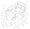
このとき、図3に示すように、第2,第4下フラップFu2,Fu4は、折目T1,T2で山折りにすることができるため、上記挿入部分24,26,32,34の各々を、それと対応する挿入口H1〜H4の各々に簡単に挿入することができる。
At this time, as shown in FIG. 3, the second and fourth lower flaps Fu2, Fu4 can be folded at the folds T1, T2, so that each of the
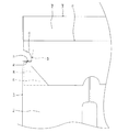
しかも、下蓋部11が構成された状態では、挿入部分24,26,32,34の端25,27,33,35が、それに挿入される挿入口H1〜H4の縁37,39,41,43に引っ掛かるようになっている。例えば、上記下蓋部11が構成された状態において、第2下フラップFu2の挿入部分24の端25は、図4に示すように、第1下フラップFu1の第1挿入口H1の縁37に引っ掛かることとなる。
Moreover, in the state in which the
次に、上蓋部10を作成する手順について説明する。
まず、第4上フラップFo4を第4側壁部S4の上辺Lo4で山折りにする。次いで、第1,第3上フラップFo1,Fo3を第1,第3側壁部S1,S3の各上辺Lo1,Lo3で同様に山折りにする。そして、図5に示すように、第2上フラップFo2を、第2側壁部S2の上辺Lo2で山折りにすると共に折目T3で山折りにすることで、第2上フラップFo2の隅部45,47(詳しくは、隅部45,47にてそれに対応する挿入口H5,H6に挿入される挿入部分)を、それと対応する第1,第3上フラップFo1,Fo3の挿入口H5,H6の各々に簡単に挿入することができる。
Next, a procedure for creating the
First, the fourth upper flap Fo4 is mountain-folded at the upper side Lo4 of the fourth side wall portion S4. Next, the first and third upper flaps Fo1 and Fo3 are similarly folded at the upper sides Lo1 and Lo3 of the first and third side wall portions S1 and S3. Then, as shown in FIG. 5, the second upper flap Fo2 is folded at the upper side Lo2 of the second side wall portion S2 and at the fold T3, so that the
このように、側壁12、下蓋部11、上蓋部10の順で作成作業を行うことにより、図2に示す1枚のシート材から包装箱1を作成することができる。
一方、包装箱1の解体作業は、以下の手順にて行うことができる。
Thus, the
On the other hand, the dismantling operation of the
まず、上蓋部10を開く。次いで、下蓋部11を開く。そして、角筒状に形成されている四方の側壁12にて接合代20で接着された部分を剥がすことで、図2の展開状態に戻り、包装箱1を解体することができる。
First, the
次に、上蓋部10を解体する(開く)手順について説明する。
まず、第2上フラップFo2の隅部45,47を第5,第6挿入口H5,H6から抜き出すと共に、第2上フラップFo2を第2側壁部S2の上辺Lo2で谷折りにする。次いで、第1,第3,第4上フラップFo1,Fo3,Fo4を第1,第3,第4側壁部S1,S3,S4の各上辺Lo1,Lo3,Lo4で谷折りにすることで、上蓋部10を解体することができる。尚、第2上フラップの隅部45,47を第5,第6挿入口から抜き出す際には、第2上フラップFo2を折目T3で山折りにするだけで、その抜き出し作業を行うことができる。
Next, a procedure for disassembling (opening) the
First, the
次に、下蓋部11を解体する手順について説明する。
まず、第1,第3下フラップFu1,Fu3の各々にて、切目L4〜L7と当該下フラップFu1,Fu3に連接している側壁部S1,S3の下辺Lu1,Lu3との間の部分を、本包装箱1の内側へ押し込む(一例を挙げると、第1下フラップFu1にて、切目L4と第1側壁部S1の下辺Lu1との間の部分を、本包装箱1の内側へ押し込む)。すると、その押し込んだ部分が撓むことにより、挿入部分24,26,32,34の端25,27,33,35と、それに対応する挿入口H1〜H4の縁37,39,41,43との引っ掛かりが解除されることとなる。例えば、第2下フラップFu2の挿入部分24の端25が第1下フラップFu1の第1挿入口H1の縁37に引っ掛かっている図4の状態から、第1下フラップFu1にて、切目L4と第1側壁部S1の下辺Lu1との間の部分を本包装箱1の内側へ押し込めば、上記引っ掛かりを解除することができる。
Next, a procedure for disassembling the
First, in each of the first and third lower flaps Fu1 and Fu3, a portion between the cuts L4 to L7 and the lower sides Lu1 and Lu3 of the side wall portions S1 and S3 connected to the lower flaps Fu1 and Fu3, Push into the inside of the packaging box 1 (for example, the first lower flap Fu1 pushes the portion between the cut L4 and the lower side Lu1 of the first side wall portion S1 into the inside of the packaging box 1). Then, when the pushed portion is bent, the ends 25, 27, 33, and 35 of the
次いで、第2下フラップFu2の挿入部分24,26及び第4下フラップFu4の挿入部分32,34を、それに対応する挿入口H1〜H4から抜き出すと共に、第2,第4下フラップFu2,Fu4を第2,第4側壁部S2,S4の各下辺Lu2,Lu4で谷折りにする。そして、第1,第3下フラップFu1,Fu3を、第1,第3側壁部S1,S3の各下辺Lu1,Lu3で谷折りにすることで下蓋部11を解体することができる。尚、上記挿入部分24,26,32,34の各々を各挿入口H1〜H4から抜き出す際には、第2,第4下フラップFu2,Fu4を折目T1,T2で山折りにするだけで、その抜き出し作業を行うことができる。
Next, the
以上のような第1実施形態の包装箱1によれば、従来の包装箱とは異なり、上記差込片が存在しないため、下蓋部11の作成作業を行う際に挿入部分24,26,32,34を意識しなくても良い。従って、下蓋部11の作成作業を容易に且つ迅速に実施することができる。また更に、折目T1,T2が形成されているため、下蓋部11の作成作業がより一層容易になる。
According to the
そして、挿入部分24,26,32,34が挿入口H1〜H4に挿入されている状態では、挿入部分24,26,32,34の端25,27,33,35が挿入口H1〜H4の縁37,39,41,43に引っ掛かることとなるため、下蓋部11が簡単に解体してしまうことを防止することができる。
When the
また更に、上述の如く引っ掛かっている部分を解除する際(即ち、下蓋部11を解体する際)には、第1,第3下フラップFu1,Fu3を撓ませる必要があるため、上記引っ掛かっている部分が撓んでいるか否かにより、下蓋部11が開けられた(解体された)か否かを確認することができる。
Furthermore, when releasing the hooked portion as described above (that is, when disassembling the lower lid portion 11), it is necessary to bend the first and third lower flaps Fu1 and Fu3. Whether or not the
尚、第1〜第4下フラップFu1〜Fu4及び第2上フラップFo2の切り欠きC5〜C9は、本包装箱1を解体する際に指を掛けて使用すると便利である。また、第2,第4側壁部S2,S4の穴h1,h2は、指を掛けるための穴として使用しても良い。例えば、包装箱1を持ち運ぶ際に、指を掛けて使用すると便利である。
Note that the cutouts C5 to C9 of the first to fourth lower flaps Fu1 to Fu4 and the second upper flap Fo2 are convenient to use with fingers when the
また、本実施形態では、第1下フラップFu1が第1蓋用フラップに相当し、第2下フラップFu2が第2蓋用フラップに相当し、第3下フラップFu3が第3蓋用フラップに相当し、第4下フラップFu4が第4蓋用フラップに相当し、下蓋部11が蓋部に相当する。そして、第2,第4下フラップFu2,Fu4の隅部21,23,29,31が、挿入用隅部に相当する。
In the present embodiment, the first lower flap Fu1 corresponds to the first lid flap, the second lower flap Fu2 corresponds to the second lid flap, and the third lower flap Fu3 corresponds to the third lid flap. The fourth lower flap Fu4 corresponds to the fourth lid flap, and the
また、本実施形態では、第2,第4下フラップFu2,Fu4の隅部21,23,29,31の全てがそれに対応する挿入口H1〜H4に挿入されるように構成していたが、これに限らず、第2,第4下フラップFu2,Fu4の隅部21,23,29,31のうちの少なくとも一つが折り曲げられることなく挿入される挿入口が形成されていれば良い。例えば、第1挿入口H1及び第4挿入口H4が、第1下フラップFu1に形成されていなくても良い。この場合、上述の如く、第1,第3下フラップFu1,Fu3を山折りにしてから、第2下フラップFu2の挿入部分26及び第4下フラップFu4の挿入部分32を第3下フラップFu3の第2,第3挿入口H2,H3に挿入すれば下蓋部11を作成することができる。但し、本包装箱1の方が、下蓋部11の保持強度の面においては有利である。
In the present embodiment, the
また、第2上フラップFo2に、第2下フラップFu2の切り欠きC1,C2と同様の切り欠きを形成しても良い。この場合、上蓋部10が容易に解体してしまうのを防止することができる。尚、この変形例では、第2上フラップFo2の隅部45,47が挿入用隅部に相当し、第1〜第4上フラップFo1〜Fo4が第1〜第4蓋用フラップに相当する。
Further, notches similar to the notches C1 and C2 of the second lower flap Fu2 may be formed in the second upper flap Fo2. In this case, it is possible to prevent the
一方また、第2上フラップFo2の第3上フラップFo3側だけに、第2下フラップFu2の切り欠きC2と同様の切り欠きを形成しても良い。この場合、第1上フラップFo1の第5挿入口H5は形成されていなくても良い。 On the other hand, a cutout similar to the cutout C2 of the second lower flap Fu2 may be formed only on the third upper flap Fo3 side of the second upper flap Fo2. In this case, the fifth insertion opening H5 of the first upper flap Fo1 may not be formed.
そして、このような変形例の包装箱では、上蓋部10を作成する際に、第1実施形態の包装箱1における上蓋部10を作成する手順と同じ手順で作成しても良いが、例えば、第1上フラップFo1→第4上フラップFo4→第3上フラップFo3の順で、各フラップFo1,Fo4,Fo3をそれに連接している側壁部S1,S4,S3の上辺Lo1,Lo4,Lo3で山折りにしてから、残る第2上フラップFo2の隅部47を第6挿入口H6に挿入する、といった手順を採れば、より上蓋部10が開きにくくなる(解体しにくくなる)。尚、この変形例では、第2上フラップFo2の隅部47が挿入用隅部に相当する。
And in the packaging box of such a modification, when creating the
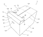
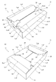
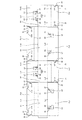
次に、第2実施形態の包装箱について図6及び図7を用い説明する。尚、図6は、第2実施形態の包装箱2の組立状態における斜視図であり、同図(a)は上蓋部10を上側、同図(b)は下蓋部11を上側としている。また、図7は、同包装箱2の展開状態における平面図である。また、図6及び図7において、第1実施形態の包装箱1と同様の構成要素については、同じ符号を付しているため、詳細な説明は省略する。
Next, the packaging box of 2nd Embodiment is demonstrated using FIG.6 and FIG.7. FIG. 6 is a perspective view of the
図6及び図7に示すように、第2実施形態の包装箱2は、第1実施形態の包装箱1と比較すると以下の(1−1)〜(1−3)の点が異なっている。
(1−1)第1〜第4側壁部S1〜S4は、それらの上辺Lo1〜Lo4または下辺Lu1〜Lu4が一直線上に並んだ状態となる図7の展開状態において、左側からS4→S1→S2→S3の順に形成されている。尚、接合代20は、第4側壁部S4の辺のうち、第1側壁部S1側と反対側の辺に連接されている。
As shown in FIGS. 6 and 7, the
(1-1) The first to fourth side wall portions S1 to S4 are S4 → S1 → from the left side in the expanded state of FIG. 7 in which the upper sides Lo1 to Lo4 or the lower sides Lu1 to Lu4 are aligned in a straight line. They are formed in the order of S2 → S3. In addition, the joining
(1−2)第2側壁部S2において、上辺Lo2及び下辺Lu2の長さよりも、その上辺Lo2及び下辺Lu2に垂直な一対の辺の長さの方が短くなっていると共に、上辺Lo2及び下辺Lu2の長さは、第1側壁部S1の上辺Lo1及び下辺Lu1の長さよりも長い。 (1-2) In the second side wall portion S2, the length of the pair of sides perpendicular to the upper side Lo2 and the lower side Lu2 is shorter than the lengths of the upper side Lo2 and the lower side Lu2, and the upper side Lo2 and the lower side The length of Lu2 is longer than the lengths of the upper side Lo1 and the lower side Lu1 of the first side wall portion S1.
(1−3)第1〜第4側壁部S1〜S4の各上辺Lo1〜Lo4には、第1〜第4上フラップFo1〜Fo4に代えて、第1〜第4上フラップFo5〜Fo8が連接されている。 (1-3) The first to fourth upper flaps Fo5 to Fo8 are connected to the upper sides Lo1 to Lo4 of the first to fourth side wall portions S1 to S4 in place of the first to fourth upper flaps Fo1 to Fo4. Has been.
具体的に説明すると、第1上フラップFo5は、略長方形であり、第2下フラップFu2と同様の切り欠きC1,C2及び折目T1が形成されている。また、第2上フラップFo6は、長方形であり、第3下フラップFu3と同様の第2,第3挿入口H2,H3及び切目L7,L6が形成されている。そして、第3上フラップFo7は、略長方形であり、第4下フラップFu4と同様の切り欠きC3,C4及び折目T2が形成されている。また、第4上フラップFo8は、長方形であり、第1下フラップFu1と同様の第1,第4挿入口H1,H4及び切目L4,L5が形成されている。更に、第1上フラップFo5は第3上フラップFo7と合同であり、第2上フラップFo6は第4上フラップFo8と合同である。 Specifically, the first upper flap Fo5 is substantially rectangular, and notches C1 and C2 and the crease T1 are formed in the same manner as the second lower flap Fu2. The second upper flap Fo6 has a rectangular shape, and second and third insertion ports H2 and H3 and cuts L7 and L6 are formed in the same manner as the third lower flap Fu3. The third upper flap Fo7 has a substantially rectangular shape, and is formed with notches C3 and C4 and a crease T2 similar to the fourth lower flap Fu4. The fourth upper flap Fo8 has a rectangular shape, and is formed with first and fourth insertion holes H1 and H4 and cut lines L4 and L5 similar to the first lower flap Fu1. Further, the first upper flap Fo5 is congruent with the third upper flap Fo7, and the second upper flap Fo6 is congruent with the fourth upper flap Fo8.
以上のような構成の包装箱2では、下蓋部11を上述した第1実施形態の包装箱1と同様に作成及び解体を実施することができる。
ところで、上蓋部10と下蓋部11とを比較すると、第1上フラップFo5が第2下フラップFu2と同じ役割を果たすものであり、第2上フラップFo6が第3下フラップFu3と同じ役割を果たすものであり、第3上フラップFo7が第4下フラップFu4と同じ役割を果たすものであり、第4上フラップFo8が第1下フラップFu1と同じ役割を果たすものである。このため、本包装箱2の上蓋部10の作成及び解体作業は、下蓋部11と同様の手順で実施することができる。
In the
By the way, when the
尚、本実施形態では、第1下フラップFu1及び第4上フラップFo8が第1蓋用フラップに相当し、第2下フラップFu2及び第1上フラップFo5が第2蓋用フラップに相当し、第3下フラップFu3及び第2上フラップFo6が第3蓋用フラップに相当し、第4下フラップFu4及び第3上フラップFo7が第4蓋用フラップに相当する。そして、下蓋部11及び上蓋部10が蓋部に相当する。また、第2,第4下フラップFu2,Fu4及び第1,第3上フラップFo5,Fo7の隅部21,23,29,31が、挿入用隅部に相当する。
In the present embodiment, the first lower flap Fu1 and the fourth upper flap Fo8 correspond to the first lid flap, the second lower flap Fu2 and the first upper flap Fo5 correspond to the second lid flap, The third lower flap Fu3 and the second upper flap Fo6 correspond to a third lid flap, and the fourth lower flap Fu4 and the third upper flap Fo7 correspond to a fourth lid flap. And the
次に、第3実施形態の包装箱について、図8及び図9を用い説明する。尚、図8は、第3実施形態の包装箱3の組立状態における斜視図であり、同図(a)は上蓋部10を上側、同図(b)は下蓋部11を上側としている。また、図9は、同包装箱3の展開状態における平面図である。また、図8及び図9において、第1実施形態の包装箱1と同様の構成要素については、同じ符号を付しているため、詳細な説明は省略する。
Next, the packaging box of 3rd Embodiment is demonstrated using FIG.8 and FIG.9. FIG. 8 is a perspective view of the
図8及び図9に示すように、第3実施形態の包装箱3は、第1実施形態の包装箱1と比較すると以下の(2−1)〜(2−2)の点が異なっている。
(2−1)第2側壁部S2において、上辺Lo2及び下辺Lu2の長さよりも、その上辺Lo2及び下辺Lu2に垂直な一対の辺の長さの方が短くなっている。
As shown in FIGS. 8 and 9, the
(2-1) In the second side wall portion S2, the length of the pair of sides perpendicular to the upper side Lo2 and the lower side Lu2 is shorter than the lengths of the upper side Lo2 and the lower side Lu2.
(2−2)第1〜第4側壁部S1〜S4の各上辺Lo1〜Lo4には、第1〜第4上フラップFo1〜Fo4に代えて、第1〜第4上フラップFo9〜Fo12が連接されている。 (2-2) The first to fourth upper flaps Fo9 to Fo12 are connected to the upper sides Lo1 to Lo4 of the first to fourth side wall portions S1 to S4 in place of the first to fourth upper flaps Fo1 to Fo4. Has been.
具体的に説明すると、第1上フラップFo9は、略長方形であり、第2下フラップFu2と同様の切り欠きC1,C2及び折目T1が形成されている。更に、第1上フラップFo9には、当該第1上フラップFu9の辺のうち、先端側の辺を分断する切り欠きC10が挿入部分24の第2上フラップFo10側の端に沿って形成されていると共に、同じく先端側の辺を分断する切り欠きC11が挿入部分26の第2上フラップFo10側とは反対側の端に沿って形成されている。
More specifically, the first upper flap Fo9 is substantially rectangular, and notches C1 and C2 and the fold line T1 are formed in the same manner as the second lower flap Fu2. Further, the first upper flap Fo9 is formed with a cutout C10 that divides the side on the tip side of the side of the first upper flap Fu9 along the end of the
また、第2上フラップFo10は、長方形であり、第3下フラップFu3と同様の第2,第3挿入口H2,H3及び切目L7,L6が形成されている。
そして、第3上フラップFo11は、略長方形であり、第4下フラップFu4と同様の切り欠きC3,C4及び折目T2が形成されている。更に、第3上フラップFo11には、第1上フラップFo9の切り欠きC10,C11と同様の切り欠きC12,C13が形成されている。
The second upper flap Fo10 has a rectangular shape, and second and third insertion ports H2 and H3 and cuts L7 and L6 are formed in the same manner as the third lower flap Fu3.
The third upper flap Fo11 has a substantially rectangular shape, and the same cutouts C3 and C4 as the fourth lower flap Fu4 and a fold T2 are formed. Further, notches C12 and C13 similar to the notches C10 and C11 of the first upper flap Fo9 are formed in the third upper flap Fo11.
また、第4上フラップFo12は、長方形であり、第1下フラップFu1と同様の第1,第4挿入口H1,H4及び切目L4,L5が形成されている。更に、第1上フラップFo9は第3上フラップFo11と合同であり、第2上フラップFo10は第4上フラップFo12と合同である。 The fourth upper flap Fo12 has a rectangular shape, and is formed with first and fourth insertion holes H1 and H4 and cut lines L4 and L5 similar to the first lower flap Fu1. Further, the first upper flap Fo9 is congruent with the third upper flap Fo11, and the second upper flap Fo10 is congruent with the fourth upper flap Fo12.
以上のような構成の包装箱3では、下蓋部11を上述した第1実施形態の包装箱1と同様に作成及び解体を実施することができる。
ところで、上蓋部10と下蓋部11とを比較すると、第1上フラップFo9が第2下フラップFu2と同じ役割を果たすものであり、第2上フラップFo10が第3下フラップFu3と同じ役割を果たすものであり、第3上フラップFo11が第4下フラップFu4と同じ役割を果たすものであり、第4上フラップFo12が第1下フラップFu1と同じ役割を果たすものである。このため、本包装箱3の上蓋部10の作成及び解体作業は、下蓋部11と同様の作業手順で実施することができる。
In the
By the way, when the
尚、本実施形態では、第1下フラップFu1及び第4上フラップFo12が第1蓋用フラップに相当し、第2下フラップFu2及び第1上フラップFo9が第2蓋用フラップに相当し、第3下フラップFu3及び第2上フラップFo10が第3蓋用フラップに相当し、第4下フラップFu4及び第3上フラップFo11が第4蓋用フラップに相当する。そして、下蓋部11及び上蓋部10が蓋部に相当する。また、第2,第4下フラップFu2,Fu4及び第1,第3上フラップFo9,Fo11の隅部21,23,29,31が、挿入用隅部に相当する。
In the present embodiment, the first lower flap Fu1 and the fourth upper flap Fo12 correspond to the first lid flap, the second lower flap Fu2 and the first upper flap Fo9 correspond to the second lid flap, The third lower flap Fu3 and the second upper flap Fo10 correspond to a third lid flap, and the fourth lower flap Fu4 and the third upper flap Fo11 correspond to a fourth lid flap. And the
以上、本発明の実施形態について説明したが、本発明は、種々の形態を採り得ることは言うまでもない。
包装箱の材質は、段ボール紙に限らず、例えば、可撓性のあるプラスチックや厚紙などを用いても良い。
As mentioned above, although embodiment of this invention was described, it cannot be overemphasized that this invention can take a various form.
The material of the packaging box is not limited to corrugated cardboard, and for example, flexible plastic or cardboard may be used.
1,2,3…包装箱、10…上蓋部、11…下蓋部、12…側壁、S1〜S4…第1〜第4側壁部、Lo1〜Lo4…第1〜第4側壁部の上辺、Lu1〜Lu4…第1〜第4側壁部の下辺、Fo1〜Fo4,Fo5〜Fo8,Fo9〜Fo12…第1〜第4上フラップ、Fu1〜Fu4…第1〜第4下フラップ、21,23,29,31…隅部、24,26,32,34…挿入部分、25,27,33,35…端、37,39,41,43…縁、C1〜C4…切り欠き、H1〜H4…第1〜第4挿入口、L4〜L7…切目、T1,T2…折目
1, 2, 3 ... packaging box, 10 ... upper lid part, 11 ... lower lid part, 12 ... side wall, S1-S4 ... first to fourth side wall parts, Lo1-Lo4 ... upper side of first to fourth side wall parts, Lu1 to Lu4: lower side of first to fourth side walls, Fo1 to Fo4, Fo5 to Fo8, Fo9 to Fo12 ... first to fourth upper flaps, Fu1 to Fu4 ... first to fourth
Claims (4)
該筒体部の一方の端部における互いに向かい合う2組の辺のうちの1組の各辺にそれぞれ連接され、該各辺で前記筒体部の内側方向へ折り曲げられることにより該筒体部の前記端部側の開口全体又は一部を覆う第1蓋用フラップ及び第3蓋用フラップと、
前記筒体部の前記2組の辺のうちの他方の1組の各辺にそれぞれ連接され、該各辺で前記筒体部の内側方向へ折り曲げられることにより該筒体部の前記開口全体又は一部を覆う第2蓋用フラップ及び第4蓋用フラップと、
を備えた包装箱であって、
前記第1蓋用フラップ及び第3蓋用フラップのうちの少なくとも一方には、当該第1蓋用フラップ及び第3蓋用フラップが前記第2蓋用フラップ及び第4蓋用フラップと共に前記開口全体又は一部を覆う蓋部となる際に、前記第2蓋用フラップにおける先端側の両方の隅部及び前記第4蓋用フラップにおける先端側の両方の隅部のうちの少なくとも一つが折り曲げられることなく挿入される挿入口が形成され、
該挿入口に挿入される隅部(以下、挿入用隅部という)を有する蓋用フラップには、該挿入用隅部にて前記挿入口に挿入される挿入部分の前記筒体部側の端に沿って切り欠きが形成され、
前記挿入部分が前記挿入口に挿入されている状態では、前記挿入部分における前記切り欠き側の端が、前記挿入口の縁のうち、前記挿入部分が挿入されてくる方向の上流側の縁に引っ掛かるようになっていること、
を特徴とする包装箱。 A cylindrical body composed of four rectangular side walls;
The cylindrical body portion is connected to each of a set of two sides facing each other at one end of the cylindrical body portion, and is bent toward the inside of the cylindrical body portion at each side, whereby the cylindrical body portion A first lid flap and a third lid flap covering the whole or part of the opening on the end side;
Each of the two sets of sides of the cylindrical body part is connected to each other side of the other set, and is bent toward the inner side of the cylindrical body part at each side, whereby the entire opening of the cylindrical body part or A second lid flap and a fourth lid flap covering a part;
A packaging box comprising:
At least one of the first lid flap and the third lid flap includes the first lid flap and the third lid flap together with the second lid flap and the fourth lid flap, When the cover portion is partially covered, at least one of both the corner portions on the front end side of the second lid flap and the both corner portions on the front end side of the fourth lid flap is not bent. An insertion slot to be inserted is formed,
The lid flap having a corner portion (hereinafter referred to as an insertion corner portion) to be inserted into the insertion port has an end on the cylindrical body side of the insertion portion to be inserted into the insertion port at the insertion corner portion. A notch is formed along the
In a state where the insertion portion is inserted into the insertion port, the notch side end of the insertion portion is an upstream edge of the insertion port in the direction in which the insertion portion is inserted. To be caught,
A packaging box featuring.
前記挿入口が形成された蓋用フラップには、前記挿入口の前記上流側の縁から延びた切目が形成されており、
前記挿入部分が前記挿入口に挿入されている状態で、前記挿入口が形成された蓋用フラップにて、前記切目と当該蓋用フラップの前記筒体部と連接している辺との間の部分が前記筒体部の内側へ押し込まれることにより、前記挿入部分の前記切り欠き側の端と前記挿入口の前記上流側の縁との引っ掛かりが解除されるようになっていること、
を特徴とする包装箱。 In the packaging box according to claim 1,
The flap for lid in which the insertion port is formed has a cut extending from the upstream edge of the insertion port,
In the state where the insertion portion is inserted into the insertion port, the lid flap formed with the insertion port, between the cut and the side connected to the cylindrical portion of the lid flap. When the portion is pushed into the inside of the cylindrical body portion, the catch between the notch side end of the insertion portion and the upstream edge of the insertion port is released,
A packaging box featuring.
前記挿入用隅部を有する蓋用フラップには、当該蓋用フラップの前記筒体部と連接している辺に平行な折目が形成されていること、
を特徴とする包装箱。 In the packaging box according to claim 1 or claim 2,
In the lid flap having the insertion corner, a fold parallel to the side connected to the cylindrical body portion of the lid flap is formed,
A packaging box featuring.
材質が段ボール紙であることを特徴とする包装箱。 In the packaging box according to any one of claims 1 to 3,
A packaging box characterized in that the material is corrugated paper.
Priority Applications (1)
| Application Number | Priority Date | Filing Date | Title |
|---|---|---|---|
| JP2004119184A JP2005298029A (en) | 2004-04-14 | 2004-04-14 | Packaging box |
Applications Claiming Priority (1)
| Application Number | Priority Date | Filing Date | Title |
|---|---|---|---|
| JP2004119184A JP2005298029A (en) | 2004-04-14 | 2004-04-14 | Packaging box |
Publications (1)
| Publication Number | Publication Date |
|---|---|
| JP2005298029A true JP2005298029A (en) | 2005-10-27 |
Family
ID=35330053
Family Applications (1)
| Application Number | Title | Priority Date | Filing Date |
|---|---|---|---|
| JP2004119184A Pending JP2005298029A (en) | 2004-04-14 | 2004-04-14 | Packaging box |
Country Status (1)
| Country | Link |
|---|---|
| JP (1) | JP2005298029A (en) |
Citations (1)
| Publication number | Priority date | Publication date | Assignee | Title |
|---|---|---|---|---|
| JPS54123221U (en) * | 1978-02-10 | 1979-08-29 |
-
2004
- 2004-04-14 JP JP2004119184A patent/JP2005298029A/en active Pending
Patent Citations (1)
| Publication number | Priority date | Publication date | Assignee | Title |
|---|---|---|---|---|
| JPS54123221U (en) * | 1978-02-10 | 1979-08-29 |
Similar Documents
| Publication | Publication Date | Title |
|---|---|---|
| JP4606141B2 (en) | Plastic box | |
| JP6808938B2 (en) | Packaging box | |
| JP5971967B2 (en) | Packaging box | |
| JP6967240B2 (en) | tray | |
| JP2017047905A (en) | Packing box with flap standing-state retaining function | |
| JP2005298029A (en) | Packaging box | |
| JP3071023U (en) | Hanging packaging box | |
| JP3100554U (en) | Packaging box | |
| JP3215759U (en) | Packaging box with flap | |
| JP4678040B2 (en) | Assembled packing box | |
| JP3153211U (en) | Packaging box | |
| JP3160659U (en) | Assembly packaging box with integrated lid | |
| JP3136547U (en) | Slide case | |
| JP6328163B2 (en) | Packaging container | |
| JP2003237773A (en) | Fruit and vegetable storage box | |
| JP3144451U (en) | Packaging container | |
| JP7298470B2 (en) | packaging box | |
| JP4748505B2 (en) | Paper container | |
| JP2012166813A (en) | Yakitori box | |
| JP2011173634A (en) | Packaging box | |
| JP2006341909A (en) | Corrugated cardboard box having deforming function | |
| JP2019127296A (en) | Packing box with flap | |
| JP2023142950A (en) | Connection type packing box | |
| JP2025043529A (en) | Packaging box | |
| JP6626019B2 (en) | Packaging containers and blanks |
Legal Events
| Date | Code | Title | Description |
|---|---|---|---|
| A621 | Written request for application examination |
Free format text: JAPANESE INTERMEDIATE CODE: A621 Effective date: 20070227 |
|
| A977 | Report on retrieval |
Free format text: JAPANESE INTERMEDIATE CODE: A971007 Effective date: 20090707 |
|
| A131 | Notification of reasons for refusal |
Effective date: 20090804 Free format text: JAPANESE INTERMEDIATE CODE: A131 |
|
| A521 | Written amendment |
Effective date: 20091001 Free format text: JAPANESE INTERMEDIATE CODE: A523 |
|
| A02 | Decision of refusal |
Effective date: 20100406 Free format text: JAPANESE INTERMEDIATE CODE: A02 |